US8888875B2 - Methods for feedstock pretreatment and transport to gasification - Google Patents

Methods for feedstock pretreatment and transport to gasification Download PDF

Info

Publication number
US8888875B2
US8888875B2 US11/646,685 US64668506A US8888875B2 US 8888875 B2 US8888875 B2 US 8888875B2 US 64668506 A US64668506 A US 64668506A US 8888875 B2 US8888875 B2 US 8888875B2
Authority
US
United States
Prior art keywords
feedstock
carbon dioxide
stream
gasifier
gasification
Prior art date
Legal status (The legal status is an assumption and is not a legal conclusion. Google has not performed a legal analysis and makes no representation as to the accuracy of the status listed.)
Active, expires
Application number
US11/646,685
Other versions
US20080155899A1 (en
Inventor
Pritham Ramamurthy
Current Assignee (The listed assignees may be inaccurate. Google has not performed a legal analysis and makes no representation or warranty as to the accuracy of the list.)
Kellogg Brown and Root LLC
Original Assignee
Kellogg Brown and Root LLC
Priority date (The priority date is an assumption and is not a legal conclusion. Google has not performed a legal analysis and makes no representation as to the accuracy of the date listed.)
Filing date
Publication date
Application filed by Kellogg Brown and Root LLC filed Critical Kellogg Brown and Root LLC
Priority to US11/646,685 priority Critical patent/US8888875B2/en
Assigned to KELLOGG BROWN & ROOT LLC reassignment KELLOGG BROWN & ROOT LLC ASSIGNMENT OF ASSIGNORS INTEREST (SEE DOCUMENT FOR DETAILS). Assignors: RAMAMURTHY, PRITHAM
Priority to PCT/US2007/025023 priority patent/WO2008082460A1/en
Publication of US20080155899A1 publication Critical patent/US20080155899A1/en
Application granted granted Critical
Publication of US8888875B2 publication Critical patent/US8888875B2/en
Assigned to BANK OF AMERICA, N.A., AS ADMINISTRATIVE AGENT reassignment BANK OF AMERICA, N.A., AS ADMINISTRATIVE AGENT SECURITY INTEREST (SEE DOCUMENT FOR DETAILS). Assignors: KELLOGG BROWN & ROOT LLC
Active legal-status Critical Current
Adjusted expiration legal-status Critical

Links

Images

Classifications

    • CCHEMISTRY; METALLURGY
    • C10PETROLEUM, GAS OR COKE INDUSTRIES; TECHNICAL GASES CONTAINING CARBON MONOXIDE; FUELS; LUBRICANTS; PEAT
    • C10JPRODUCTION OF PRODUCER GAS, WATER-GAS, SYNTHESIS GAS FROM SOLID CARBONACEOUS MATERIAL, OR MIXTURES CONTAINING THESE GASES; CARBURETTING AIR OR OTHER GASES
    • C10J3/00Production of combustible gases containing carbon monoxide from solid carbonaceous fuels
    • C10J3/72Other features
    • C10J3/86Other features combined with waste-heat boilers
    • CCHEMISTRY; METALLURGY
    • C10PETROLEUM, GAS OR COKE INDUSTRIES; TECHNICAL GASES CONTAINING CARBON MONOXIDE; FUELS; LUBRICANTS; PEAT
    • C10JPRODUCTION OF PRODUCER GAS, WATER-GAS, SYNTHESIS GAS FROM SOLID CARBONACEOUS MATERIAL, OR MIXTURES CONTAINING THESE GASES; CARBURETTING AIR OR OTHER GASES
    • C10J3/00Production of combustible gases containing carbon monoxide from solid carbonaceous fuels
    • C10J3/72Other features
    • C10J3/78High-pressure apparatus
    • CCHEMISTRY; METALLURGY
    • C10PETROLEUM, GAS OR COKE INDUSTRIES; TECHNICAL GASES CONTAINING CARBON MONOXIDE; FUELS; LUBRICANTS; PEAT
    • C10KPURIFYING OR MODIFYING THE CHEMICAL COMPOSITION OF COMBUSTIBLE GASES CONTAINING CARBON MONOXIDE
    • C10K1/00Purifying combustible gases containing carbon monoxide
    • C10K1/02Dust removal
    • C10K1/024Dust removal by filtration
    • CCHEMISTRY; METALLURGY
    • C10PETROLEUM, GAS OR COKE INDUSTRIES; TECHNICAL GASES CONTAINING CARBON MONOXIDE; FUELS; LUBRICANTS; PEAT
    • C10KPURIFYING OR MODIFYING THE CHEMICAL COMPOSITION OF COMBUSTIBLE GASES CONTAINING CARBON MONOXIDE
    • C10K1/00Purifying combustible gases containing carbon monoxide
    • C10K1/04Purifying combustible gases containing carbon monoxide by cooling to condense non-gaseous materials
    • CCHEMISTRY; METALLURGY
    • C10PETROLEUM, GAS OR COKE INDUSTRIES; TECHNICAL GASES CONTAINING CARBON MONOXIDE; FUELS; LUBRICANTS; PEAT
    • C10KPURIFYING OR MODIFYING THE CHEMICAL COMPOSITION OF COMBUSTIBLE GASES CONTAINING CARBON MONOXIDE
    • C10K1/00Purifying combustible gases containing carbon monoxide
    • C10K1/08Purifying combustible gases containing carbon monoxide by washing with liquids; Reviving the used wash liquors
    • C10K1/10Purifying combustible gases containing carbon monoxide by washing with liquids; Reviving the used wash liquors with aqueous liquids
    • C10K1/101Purifying combustible gases containing carbon monoxide by washing with liquids; Reviving the used wash liquors with aqueous liquids with water only
    • CCHEMISTRY; METALLURGY
    • C10PETROLEUM, GAS OR COKE INDUSTRIES; TECHNICAL GASES CONTAINING CARBON MONOXIDE; FUELS; LUBRICANTS; PEAT
    • C10KPURIFYING OR MODIFYING THE CHEMICAL COMPOSITION OF COMBUSTIBLE GASES CONTAINING CARBON MONOXIDE
    • C10K3/00Modifying the chemical composition of combustible gases containing carbon monoxide to produce an improved fuel, e.g. one of different calorific value, which may be free from carbon monoxide
    • C10K3/001Modifying the chemical composition of combustible gases containing carbon monoxide to produce an improved fuel, e.g. one of different calorific value, which may be free from carbon monoxide by thermal treatment
    • CCHEMISTRY; METALLURGY
    • C10PETROLEUM, GAS OR COKE INDUSTRIES; TECHNICAL GASES CONTAINING CARBON MONOXIDE; FUELS; LUBRICANTS; PEAT
    • C10KPURIFYING OR MODIFYING THE CHEMICAL COMPOSITION OF COMBUSTIBLE GASES CONTAINING CARBON MONOXIDE
    • C10K3/00Modifying the chemical composition of combustible gases containing carbon monoxide to produce an improved fuel, e.g. one of different calorific value, which may be free from carbon monoxide
    • C10K3/02Modifying the chemical composition of combustible gases containing carbon monoxide to produce an improved fuel, e.g. one of different calorific value, which may be free from carbon monoxide by catalytic treatment
    • C10K3/04Modifying the chemical composition of combustible gases containing carbon monoxide to produce an improved fuel, e.g. one of different calorific value, which may be free from carbon monoxide by catalytic treatment reducing the carbon monoxide content, e.g. water-gas shift [WGS]
    • CCHEMISTRY; METALLURGY
    • C10PETROLEUM, GAS OR COKE INDUSTRIES; TECHNICAL GASES CONTAINING CARBON MONOXIDE; FUELS; LUBRICANTS; PEAT
    • C10JPRODUCTION OF PRODUCER GAS, WATER-GAS, SYNTHESIS GAS FROM SOLID CARBONACEOUS MATERIAL, OR MIXTURES CONTAINING THESE GASES; CARBURETTING AIR OR OTHER GASES
    • C10J2300/00Details of gasification processes
    • C10J2300/09Details of the feed, e.g. feeding of spent catalyst, inert gas or halogens
    • C10J2300/0903Feed preparation
    • CCHEMISTRY; METALLURGY
    • C10PETROLEUM, GAS OR COKE INDUSTRIES; TECHNICAL GASES CONTAINING CARBON MONOXIDE; FUELS; LUBRICANTS; PEAT
    • C10JPRODUCTION OF PRODUCER GAS, WATER-GAS, SYNTHESIS GAS FROM SOLID CARBONACEOUS MATERIAL, OR MIXTURES CONTAINING THESE GASES; CARBURETTING AIR OR OTHER GASES
    • C10J2300/00Details of gasification processes
    • C10J2300/09Details of the feed, e.g. feeding of spent catalyst, inert gas or halogens
    • C10J2300/0913Carbonaceous raw material
    • C10J2300/0916Biomass
    • CCHEMISTRY; METALLURGY
    • C10PETROLEUM, GAS OR COKE INDUSTRIES; TECHNICAL GASES CONTAINING CARBON MONOXIDE; FUELS; LUBRICANTS; PEAT
    • C10JPRODUCTION OF PRODUCER GAS, WATER-GAS, SYNTHESIS GAS FROM SOLID CARBONACEOUS MATERIAL, OR MIXTURES CONTAINING THESE GASES; CARBURETTING AIR OR OTHER GASES
    • C10J2300/00Details of gasification processes
    • C10J2300/09Details of the feed, e.g. feeding of spent catalyst, inert gas or halogens
    • C10J2300/0913Carbonaceous raw material
    • C10J2300/093Coal
    • CCHEMISTRY; METALLURGY
    • C10PETROLEUM, GAS OR COKE INDUSTRIES; TECHNICAL GASES CONTAINING CARBON MONOXIDE; FUELS; LUBRICANTS; PEAT
    • C10JPRODUCTION OF PRODUCER GAS, WATER-GAS, SYNTHESIS GAS FROM SOLID CARBONACEOUS MATERIAL, OR MIXTURES CONTAINING THESE GASES; CARBURETTING AIR OR OTHER GASES
    • C10J2300/00Details of gasification processes
    • C10J2300/09Details of the feed, e.g. feeding of spent catalyst, inert gas or halogens
    • C10J2300/0913Carbonaceous raw material
    • C10J2300/0943Coke
    • CCHEMISTRY; METALLURGY
    • C10PETROLEUM, GAS OR COKE INDUSTRIES; TECHNICAL GASES CONTAINING CARBON MONOXIDE; FUELS; LUBRICANTS; PEAT
    • C10JPRODUCTION OF PRODUCER GAS, WATER-GAS, SYNTHESIS GAS FROM SOLID CARBONACEOUS MATERIAL, OR MIXTURES CONTAINING THESE GASES; CARBURETTING AIR OR OTHER GASES
    • C10J2300/00Details of gasification processes
    • C10J2300/09Details of the feed, e.g. feeding of spent catalyst, inert gas or halogens
    • C10J2300/0913Carbonaceous raw material
    • C10J2300/095Exhaust gas from an external process for purification
    • CCHEMISTRY; METALLURGY
    • C10PETROLEUM, GAS OR COKE INDUSTRIES; TECHNICAL GASES CONTAINING CARBON MONOXIDE; FUELS; LUBRICANTS; PEAT
    • C10JPRODUCTION OF PRODUCER GAS, WATER-GAS, SYNTHESIS GAS FROM SOLID CARBONACEOUS MATERIAL, OR MIXTURES CONTAINING THESE GASES; CARBURETTING AIR OR OTHER GASES
    • C10J2300/00Details of gasification processes
    • C10J2300/09Details of the feed, e.g. feeding of spent catalyst, inert gas or halogens
    • C10J2300/0953Gasifying agents
    • C10J2300/0959Oxygen
    • CCHEMISTRY; METALLURGY
    • C10PETROLEUM, GAS OR COKE INDUSTRIES; TECHNICAL GASES CONTAINING CARBON MONOXIDE; FUELS; LUBRICANTS; PEAT
    • C10JPRODUCTION OF PRODUCER GAS, WATER-GAS, SYNTHESIS GAS FROM SOLID CARBONACEOUS MATERIAL, OR MIXTURES CONTAINING THESE GASES; CARBURETTING AIR OR OTHER GASES
    • C10J2300/00Details of gasification processes
    • C10J2300/09Details of the feed, e.g. feeding of spent catalyst, inert gas or halogens
    • C10J2300/0953Gasifying agents
    • C10J2300/0969Carbon dioxide
    • CCHEMISTRY; METALLURGY
    • C10PETROLEUM, GAS OR COKE INDUSTRIES; TECHNICAL GASES CONTAINING CARBON MONOXIDE; FUELS; LUBRICANTS; PEAT
    • C10JPRODUCTION OF PRODUCER GAS, WATER-GAS, SYNTHESIS GAS FROM SOLID CARBONACEOUS MATERIAL, OR MIXTURES CONTAINING THESE GASES; CARBURETTING AIR OR OTHER GASES
    • C10J2300/00Details of gasification processes
    • C10J2300/09Details of the feed, e.g. feeding of spent catalyst, inert gas or halogens
    • C10J2300/0983Additives
    • C10J2300/0989Hydrocarbons as additives to gasifying agents to improve caloric properties
    • CCHEMISTRY; METALLURGY
    • C10PETROLEUM, GAS OR COKE INDUSTRIES; TECHNICAL GASES CONTAINING CARBON MONOXIDE; FUELS; LUBRICANTS; PEAT
    • C10JPRODUCTION OF PRODUCER GAS, WATER-GAS, SYNTHESIS GAS FROM SOLID CARBONACEOUS MATERIAL, OR MIXTURES CONTAINING THESE GASES; CARBURETTING AIR OR OTHER GASES
    • C10J2300/00Details of gasification processes
    • C10J2300/12Heating the gasifier
    • C10J2300/1207Heating the gasifier using pyrolysis gas as fuel
    • CCHEMISTRY; METALLURGY
    • C10PETROLEUM, GAS OR COKE INDUSTRIES; TECHNICAL GASES CONTAINING CARBON MONOXIDE; FUELS; LUBRICANTS; PEAT
    • C10JPRODUCTION OF PRODUCER GAS, WATER-GAS, SYNTHESIS GAS FROM SOLID CARBONACEOUS MATERIAL, OR MIXTURES CONTAINING THESE GASES; CARBURETTING AIR OR OTHER GASES
    • C10J2300/00Details of gasification processes
    • C10J2300/16Integration of gasification processes with another plant or parts within the plant
    • C10J2300/1671Integration of gasification processes with another plant or parts within the plant with the production of electricity
    • YGENERAL TAGGING OF NEW TECHNOLOGICAL DEVELOPMENTS; GENERAL TAGGING OF CROSS-SECTIONAL TECHNOLOGIES SPANNING OVER SEVERAL SECTIONS OF THE IPC; TECHNICAL SUBJECTS COVERED BY FORMER USPC CROSS-REFERENCE ART COLLECTIONS [XRACs] AND DIGESTS
    • Y02TECHNOLOGIES OR APPLICATIONS FOR MITIGATION OR ADAPTATION AGAINST CLIMATE CHANGE
    • Y02PCLIMATE CHANGE MITIGATION TECHNOLOGIES IN THE PRODUCTION OR PROCESSING OF GOODS
    • Y02P20/00Technologies relating to chemical industry
    • Y02P20/141Feedstock
    • Y02P20/145Feedstock the feedstock being materials of biological origin
    • YGENERAL TAGGING OF NEW TECHNOLOGICAL DEVELOPMENTS; GENERAL TAGGING OF CROSS-SECTIONAL TECHNOLOGIES SPANNING OVER SEVERAL SECTIONS OF THE IPC; TECHNICAL SUBJECTS COVERED BY FORMER USPC CROSS-REFERENCE ART COLLECTIONS [XRACs] AND DIGESTS
    • Y02TECHNOLOGIES OR APPLICATIONS FOR MITIGATION OR ADAPTATION AGAINST CLIMATE CHANGE
    • Y02PCLIMATE CHANGE MITIGATION TECHNOLOGIES IN THE PRODUCTION OR PROCESSING OF GOODS
    • Y02P20/00Technologies relating to chemical industry
    • Y02P20/50Improvements relating to the production of bulk chemicals
    • Y02P20/54Improvements relating to the production of bulk chemicals using solvents, e.g. supercritical solvents or ionic liquids

Definitions

  • Embodiments herein generally relate to methods for syngas production. More particularly, the embodiments relate to methods for pretreating gasification feedstocks and efficient introduction of feedstock into reactors for syngas production.
  • Gasification is a high-temperature process usually conducted at elevated pressure that converts carbon-containing material into mostly gaseous mixtures, including carbon-dioxide, carbon monoxide, hydrogen and methane. These gaseous mixtures are typically referred to as syngas.
  • syngas can be used as a feedstock to generate electricity and/or steam, a source of hydrogen, and for the production of other organic chemicals.
  • gasification adds value to low-value feedstocks by converting them to marketable products.
  • Coal, crude oil, coke, and high-sulfur residues have been used as gasification feedstock.
  • the feedstock is treated to minimize water carryover to the gasifier reactor to improve energy efficiency and lower water-shift reactions in the reactor.
  • the feedstock is reacted in a gasifier (i.e. reactor) with an oxidizing medium in a reduced (stoichiometrically oxygen-starved) atmosphere at a high temperature and (usually) high pressure.
  • a water-gas shift reaction can occur where at least a portion of the carbon monoxide, with catalyst and/or high temperature, is reacted with water to produce predominantly hydrogen and carbon dioxide.
  • the feedstock has been fed in the form of a slurry, such as a coal-water mixture or a coal-solvent mixture via pumps to transfer the feedstock from the lockhoppers to the gasifier system.
  • the feedstock is typically treated in a lockhopper system that uses one or more flow control valves to distribute the treated feedstock from the lockhopper to the reactor system.
  • Conventional lock hopper systems utilize nitrogen gas to provide an inert atmosphere therein. Nitrogen gas serves as an inert replacement for air where coal oxidation is undesirable.
  • FIG. 1 depicts an illustrative system for producing syngas utilizing a feedstock pretreatment process according to one or more embodiments described.
  • FIG. 2 depicts an illustrative system for pretreating a feedstock according to one or more embodiments described.
  • FIG. 3 depicts an illustrative system for gasifying a feedstock according to one or more embodiments described.
  • the feedstock can be pretreated with supercritical carbon dioxide.
  • Supercritical carbon dioxide can be used to release volatiles, remove moisture, increase porosity, and/or increase reactivity of the feedstocks.
  • the supercritical carbon dioxide can be obtained by compressing and cooling or heating a gasification byproduct that contains carbon dioxide.
  • the gasification byproduct can be produced from oxidation of the feedstock, combustion of syngas, and/or reactions within heat recovery systems.
  • the gasification byproduct containing carbon dioxide can be compressed and cooled or heated to supercritical conditions to produce supercritical carbon dioxide.
  • the supercritical carbon dioxide can be contacted with the feedstock prior to gasification. Recycling the carbon dioxide at supercritical conditions to the feedstock prior to gasification provides an excellent balance in stability, flexibility, efficiency and safety with low to no emissions.
  • supercritical carbon dioxide refers to a fluid containing carbon dioxide at a temperature and pressure above the critical temperature and pressure of the fluid.
  • Supercritical carbon dioxide can have physical properties between those of a liquid and gas.
  • Carbon dioxide has a critical temperature (T c ) of about 31.1° C. (88° F.) and a critical pressure (P c ) of about 73.8 bar (1070 psia).
  • the methods for gasification can be performed in a single system (i.e. train) having one or more systems for pretreating gasification feedstock, gasification systems, and compression systems.
  • the methods can be performed in two or more systems (i.e. two or more trains) that are arranged in series or parallel.
  • Each system can be configured independent from the other(s) or configured where any of the one or more pretreatment systems, gasification systems, and compression systems can be shared.
  • embodiments of the invention will be further described with reference to a single system having one or more pretreatment systems, gasification systems, and compression systems.
  • FIG. 1 depicts an illustrative system 100 for producing syngas utilizing a feedstock pretreatment process according to one or more embodiments described.
  • the system 100 for producing syngas includes one or more pretreatment systems 200 , gasification systems 300 , and recycle gas compression systems 400 .
  • each pretreatment system 200 can be used to release volatiles, remove moisture, increase porosity, increase reactivity, or any combination thereof, to provide a stream 20 containing the treated feedstock for gasification (“treated feedstock stream”).
  • the treated feedstock stream 20 can be introduced to the one or more gasification systems 300 to provide one or more streams 30 containing syngas (“syngas stream”).
  • At least a portion of the syngas stream 30 can be used to power one or more combustion turbines 500 .
  • the exhaust from the combustion turbines 500 can be directed to one or more heat recovery systems 650 and/or steam turbines 600 .
  • the combustion turbines 500 and/or heat recovery systems 650 can generate carbon dioxide.
  • the carbon dioxide can be recycled to the one or more gas compression systems 400 via stream 50 .
  • the carbon dioxide from stream 50 can be purified, compressed and heated or cooled to supercritical conditions within the compression system 400 unit operation area, and returned to the pretreatment system 200 via stream 40 (“supercritical carbon dioxide stream”).
  • at least a portion of stream 40 can be directed to the combustion turbines 500 and/or heat recovery systems 650 .
  • feedstock refers to a raw material, whether solid, gas or liquid, used to produce a syngas.
  • the feedstock can include one or more carbonaceous materials.
  • Illustrative carbonaceous materials include but are not limited to biomass (i.e, plant and/or animal matter or plant and/or animal derived matter); coal (high-sodium and low-sodium lignite, subbituminous, and/or anthracite for example); oil shale; coke; tar; heavy oil; and asphalt.
  • the carbonaceous materials can be combined with hydrocarbon-based polymeric materials such as thermoplastics, elastomers and rubbers, polypropylenes, polyethylenes, polystyrenes, including copolymers and blends thereof; heavy hydrocarbon sludge and bottoms products from petroleum refineries and petrochemical plants; derivatives thereof; and mixtures and combinations thereof.
  • hydrocarbon-based polymeric materials such as thermoplastics, elastomers and rubbers, polypropylenes, polyethylenes, polystyrenes, including copolymers and blends thereof; heavy hydrocarbon sludge and bottoms products from petroleum refineries and petrochemical plants; derivatives thereof; and mixtures and combinations thereof.
  • the feedstock can include a mixture or combination of one or more carbonaceous materials such as low ash or no ash polymer, biomass derived material, or by-product derived from manufacturing operations or produced as a result of governmental mandates to dispose of previously manufactured materials.
  • the feedstock can include one or more carbonaceous materials combined with one or more discarded consumer products such as carpet and/or car parts such as bumpers and dashboards.
  • the feedstock can include recycled plastics such as polypropylene.
  • the feedstock can include a dry feed used for high moisture fuels such as subbituminous coal and lignite.
  • the feedstock can be dried, and then pulverized by milling units such as one or more parallel bowl mills prior to feeding to the pretreatment system 200 .
  • the feedstock can have an average particle diameter size from the range of about 50 ⁇ m to about 500 ⁇ m or from about 50 ⁇ m to about 400 ⁇ m. In one or more embodiments above or elsewhere herein, the average particle diameter size of the feedstock can be in the range of from about 150 ⁇ m to about 450 ⁇ m or from about 200 ⁇ m to about 400 ⁇ m.
  • FIG. 2 depicts an illustrative system 200 for pretreating a feedstock according to one or more embodiments described.
  • the pretreatment system 200 can include one or more lock hoppers 210 , intermediate vessels 220 , and flow control valves 230 .
  • the system 200 can include one or more lockhoppers 210 , intermediate vessels 220 , and flow control valves 230 arranged in parallel or series.
  • two lock hoppers 210 first lockhopper and second lockhopper
  • accompanying flow control valves 230 first flow valve and second flow valve
  • the system 200 can allow for crushed feedstock via stream 10 to be loaded in the first lockhopper 210 and pressurized by an inert gas.
  • the pressurized feedstock can then be transferred through the first flow valve 230 into the intermediate vessel 220 by gravity via one or more feeder lines suitable in the art for the system described.
  • the pressure in the intermediate vessel 220 can be raised.
  • Feedstock in the intermediate vessel 220 can be transferred into the second lockhopper 210 by gravity via one or more feeder lines suitable in the art.
  • Treated feedstock via stream 20 can exit the second lockhopper 210 through a second flow valve 230 prior to entry into a nozzle 250 .
  • the nozzle 250 can facilitate feedstock entry into the gasification system 300 .
  • Flow control valves 230 can be of several types suitable in the art, including but not limited to rotary valves, screw feeders, and/or rotating disc valves.
  • the intermediate vessel 210 and the second lockhopper 210 can be in pressure equilibrium.
  • a valve (not shown) below the intermediate vessel 220 can be closed, thus neutralizing the pressure of the first lockhopper 210 and the intermediate vessel 220 from the rest of the series ahead of the intermediate vessel 220 .
  • the cycle of transferring and pressurizing feedstock from the intermediate vessel 220 can be repeated such that the feedstock flow from the second lockhopper 210 and second flow valve 230 can continuously feed treated feedstock via stream 20 to the nozzle 250 and gasification system 300 .
  • the raw feedstock via stream 10 can be mixed with supercritical carbon dioxide within the intermediate vessel 220 in lieu of an inert gas.
  • the supercritical carbon dioxide can be provided via stream 40 .
  • carbon dioxide can be sourced from purchased tanks to fill in the inventory as most of it can be recycled, carbon dioxide can be routed from other combustion units in the complex such as other energy sources, or nitrogen can be used.
  • the intermediate vessels 220 can be pressurized with the supercritical carbon dioxide.
  • the supercritical carbon dioxide can be used to increase the pressure within the intermediate vessels 220 to a pressure of approximately above 73.8 bar.
  • supercritical carbon dioxide can be recycled via stream 40 from the one or more compression systems 400 to increase the pressure of the intermediate vessel 220 from about atmospheric to above the critical pressure of carbon dioxide.
  • the temperature in the intermediate vessel 220 can be above or below the critical temperature of carbon dioxide. In one or more embodiments it can be desirable to have the temperature of the intermediate vessel 220 above the critical temperature of the carbon dioxide so that the fluid in the intermediate vessel 220 can be supercritical, thereby increasing feedstock residence time and release of hydrocarbons from the feedstock.
  • the supercritical carbon dioxide can provide significant improvements to the feedstock feed, including but not limited to volatiles extraction, porosity, reactivity, and reduction of particle size for better syngas quality.
  • the supercritical carbon dioxide can also increase carbon conversion, yielding higher quality syngas.
  • feedstock For gasifier reactors it can be imperative that feedstock be prepared such that the conversion of carbonaceous components of feedstock to high energy components of syngas can readily progress.
  • the conversion of feedstock can be facilitated by making volatiles readily accessible in the gasifier, increasing the surface area of feedstock particles by increasing porosity and reducing particle diameter.
  • the use of inert material to convey the coal to the reactor can result in the syngas having lower energy content per unit mass.
  • the use of carbon dioxide also can act as a source of oxidizing material for the gasification of feedstock in the gasifier, thus reducing the requirement of oxygen or an air separation unit, and reducing the inert content in the produced syngas.
  • Supercritical fluids can be regarded as “hybrid solvents” with properties between those of gases and liquids, i.e. a solvent with a low viscosity, high diffusion rates and low surface tension.
  • the viscosity can be in the range of about 20 ⁇ Pa ⁇ s to about 100 ⁇ Pa ⁇ s (about 0.02 cP to about 0.1 cP).
  • liquids have viscosities of approximately 500 ⁇ Pa ⁇ s to approximately 1000 ⁇ Pa ⁇ s (approximately 0.5 cP to approximately 1.0 cP) and gases approximately 10 ⁇ Pa ⁇ s (approximately 0.01 cP).
  • Diffusivities of solutes in supercritical carbon dioxide can be up to a factor of about 10 times higher than that in liquid solvents. These properties can be strongly pressure dependent in the vicinity of the critical point, making supercritical carbon dioxide a highly tunable solvent.
  • Supercritical carbon dioxide can extract a substantial amount of volatiles from feedstock, increase feedstock porosity, and improve gasifier reactivity.
  • the higher density of supercritical dioxide can decrease leakage across the flow valves 230 in the pretreatment system 200 resulting in increased reliability of the pretreatment or feed system.
  • the leakage rate across the flow valves 230 can be inversely proportional to the density of the gas passing therethrough.
  • liquid material can pack across a flow valve better than a gas material because the liquid material has a higher density than the gas material.
  • supercritical carbon dioxide gas cannot be as dense as a liquid, the density of supercritical carbon dioxide can be greater than that of a gas.
  • Supercritical carbon dioxide (at pressures above about 1100 psig) can have about three times higher density than compressed carbon dioxide (at pressures of about 500 psig).
  • Supercritical carbon dioxide can have substantially higher density compared to nitrogen. The substantially higher density of supercritical carbon dioxide can thus increase the efficiency of the flow valves 230 in the pretreatment system 200 .
  • the expansion of the supercritical carbon dioxide in the gasification system 300 can accelerate feedstock particles to mix with inert solids. Intimate mixing of feedstock particles with a heat source can be beneficial for the gasification system 300 operating in a short residence time mode.
  • the supercritical carbon dioxide volume can rapidly expand to below supercritical levels and cause an increase in feedstock velocity.
  • supercritical carbon dioxide can thus have substantially more volume expansion, and an increase in feedstock velocity than that of a similar volume of nitrogen resulting in a higher momentum for the feedstock to be better distributed in the reactor.
  • the nozzle 250 can be designed to maximize the acceleration of feedstock particles to penetrate a moving bed in a riser and improve mixing zone performance.
  • the pretreatment with supercritical carbon dioxide can allow the use of a wider array of raw feedstock, including coals with volatiles and coals that retain the volatiles by strong adsorption.
  • the relatively low temperature of the supercritical carbon dioxide, beginning at about the critical temperature of 31.1° C., and the stability of carbon dioxide can allow most compounds to be extracted with little solvent reactivity, feedstock damage, and feedstock denaturing.
  • the rapid expansion by depressurization and heating of the supercritical carbon dioxide in the gasification system 300 can stabilize the solids in the gasifier reactor.
  • Use of supercritical carbon dioxide in the pretreatment system 200 can improve reliability of the feed system to the gasification system 300 .
  • Utilizing the feedstock pretreatment system 200 with supercritical carbon dioxide can substantially decrease feedstock bound volatile content and improve performance of the lock hoppers 210 , intermediate vessels 220 , rotary valves 230 , feed lines, and nozzles 250 of the pretreatment system 200 .
  • the supercritical carbon dioxide can also be a promising green solvent because it can be non-toxic and efficiently recycled as a byproduct from gasification.
  • FIG. 3 depicts an illustrative system 300 for gasifying a feedstock according to one or more embodiments described.
  • the gasification system 300 can include a single reactor unit having one or more mixing zones 310 , risers 320 , disengagers 330 and cyclones 340 .
  • the solid particulates from the reactor can at least partially be removed from the syngas within one or more disengagers 330 , cyclones 340 , and/or particulate removal systems 390 .
  • the separated syngas can then be cooled and cleaned to remove contaminants including one or more sulfur-containing compounds within one or more gas cleanup systems 395 .
  • the gasification system 300 can also include two or more reactor units arranged in series or parallel. Each reactor unit can be configured independent from the others or configured where any of the one or more mixing zones 310 , risers 320 , disengagers 330 , and/or cyclones 340 can be shared. For simplicity and ease of description, embodiments of the invention will be further described in the context of a single reactor unit.
  • the treated feedstock stream 20 , oxidant, and water are combined to produce a raw syngas.
  • the oxidant can be introduced via stream 301 (“oxidant stream”).
  • the water can be introduced via stream 303 (“water stream”).
  • the one or more oxidants can include air, oxygen, essentially oxygen, oxygen-enriched air, mixtures of oxygen and air, mixtures of oxygen and gas, mixtures of oxygen and inert gas such as nitrogen or argon, and the like.
  • the one or more oxidants can be introduced into the mixing zone 310 at a rate suitable to control the temperature of the mixing zone 310 .
  • a molar ratio of oxygen to carbon in the recycled particles can be maintained at a substoichiometric proportion to promote the formation of carbon monoxide over carbon dioxide in the mixing zone 310 .
  • the oxygen supplied via the oxidant to the mixing zone 310 can be less than about five percent of the stoichiometric amount of oxygen required for complete combustion of all the carbon supplied (whether from coal, polymer and/or biomass waste) to the mixing zone 310 .
  • One or more treated feedstocks via stream 20 and one or more oxidants via stream 301 can be combined in the mixing zone 310 .
  • One or more sorbents via stream 302 (“sorbent stream”) can also be used.
  • the sorbent stream 302 can be optionally admixed with the treated feedstock stream 20 to adsorb or consume significant errant oxygen entering the mixing zone 310 at a rate and level sufficient to delay or prevent the errant oxygen from reaching a concentration that results in undesirable reactions with hydrogen.
  • the treated feedstock stream 20 and sorbent stream 302 can be mixed and fed together, or they can be fed separately to the mixing zone 310 .
  • the one or more treated feedstock streams 20 , oxidant streams 301 and optional sorbent streams 302 can be injected sequentially or simultaneously.
  • the one or more oxidants via stream 301 and water via stream 303 can be introduced at the bottom of the mixing zone 310 , operating at up to about 285 psig and about 1800 F, to raise heat by burning the carbon in the recirculated solids (“char”).
  • the treated feedstock stream 20 and optional sorbent stream 302 can be fed to the top of the mixing zone 310 to separate the treated feedstock from the oxidant and avoid burning the volatile material produced when the feedstock is heated.
  • the solids and gases can be carried from the mixing zone 310 into the riser 320 where devolatilization and carbon-steam gasification reactions can occur.
  • at least a portion of the sulfur released from the coal can be captured as calcium sulfide by the calcium in the treated feedstock or by the added calcium-based sorbent.
  • the gas with entrained solids moves up through the mixing zone 310 into the riser 320 (which can have a slightly smaller diameter).
  • the gas exits the riser 320 to enter the one or more disengagers 330 where the larger particles in the gas stream are removed by gravity separation.
  • the remaining particles can be removed in the one or more cyclones 340 .
  • the gas can exit the cyclones 340 and enter the one or more particulate removal systems 390 for further particulate removal.
  • the unreacted char and sorbent-derived material leaving the riser 330 can be captured by the disengager 330 and cyclone 340 and recycled to the mixing zone 310 through the loopseal 345 , standpipe 350 , and/or j-leg 355 .
  • the j-leg 355 can be a nonmechanical “j-valve.” Non-mechanical “y-valves” or “L-valves” can also be used. This recycling increases the effective solids residence time, increases the carbon conversion, and improves sorbent utilization.
  • the gas with entrained solids from the mixing zone 310 can enter the riser 320 where additional residence time allows char gasification, methane/steam reforming, water-shift and/or sulfur capture reactions to occur.
  • the gas velocity in the riser 320 ranges from about 3 m/s to about 28 m/s, from about 6 m/s to about 25 m/s, from about 9 m/s to about 22 m/s, from about 10 m/s to about 20 m/s, or from about 9 m/s to about 15 m/s.
  • the residence time and high temperature conditions in the riser 320 can provide for a water-shift reaction to reach equilibrium.
  • the mixing zone 310 can be operated at a moderate temperature as low as about 788° C. (1450° F.).
  • the gasifier reactor can be operated in a temperature range of from about 1050° F. to about 1900° F., from about 1540° F. to about 1710° F., or at a suitable temperature below that which would melt the ash.
  • Heat can be supplied by a startup burner 304 burning the carbon in the recirculated solids in the lower part of the mixing zone 310 before recirculated solids contact the entering feedstock.
  • Startup i.e. prior to feeding the feedstock to the mixing zone 310
  • the operating temperature of the mixing zone 310 ranges from a low of about 500° F., 750° F., or 1000° F. to a high of about 1200° F., 1500° F., or 1800° F. In one or more embodiments above or elsewhere herein, the operating temperature of the mixing zone 310 ranges from about 700° F. to about 1750° F., from about 900° F. to about 1600° F., or from about 1200° F. to about 1600° F.
  • the operating temperature can be controlled by the recirculation rate of the solids, optional heat removal from the ash prior to entering the mixing zone 310 , and oxidant 301 supply to the mixing zone 310 .
  • Excess oxygen in the air can be consumed by the recirculating solids forming primarily carbon dioxide, thereby minimizing tar formation and stabilizing reactor temperature during operation and periods of feed interruption, if any.
  • the recirculating solids also can serve to rapidly heat the incoming feedstock and minimize tar formation.
  • the mixing zone 310 can be operated at pressures from about 0 psig to about 700 psig to increase thermal output per unit reactor cross-sectional area and enhance energy output in the subsequent power cycle. In one or more embodiments above or elsewhere herein, the mixing zone 310 can be operated at pressures from about 100 psig to about 650 psig, from about 100 psig to about 600 psig, or from about 100 psig to about 550 psig.
  • the one or more particulate removal systems 390 can include one or more coolers for cooling the syngas.
  • the particulate removal systems 390 can include additional disengagers 330 and cyclones 340 which are known in the art for solids removal.
  • the particulate removal systems 390 can include one or more particulate control devices (“PCD”).
  • PCD particulate control devices
  • One or more sintered metal filters, metal filter candles, and/or ceramic filter candles (for example, iron aluminide filter material) can be used as a PCD.
  • the one or more gas cleanup systems 395 can include one or more coolers for cooling the syngas.
  • the gas cleanup systems 395 can include water quench, radiant and convective coolers, chemical quench and gas recycle quench to cool the syngas.
  • the gas cleanup system 395 can further include one or more primary coolers (not shown) or syngas heat recovery systems (not shown).
  • the primary cooler or syngas heat recovery system can be used to recover heat from the high-temperature gasifier operation. Heat recovery can reclaim 5 to 25 percent of the energy in the feed depending on the process conditions.
  • the raw syngas leaving the gasifier reactor flows to the heat recovery system where the syngas can be cooled by radiant and/or convective exchange.
  • the raw syngas can be cooled by a direct quench system, wherein water or cool recycle gas is injected into the hot raw syngas.
  • the syngas can then pass through a series of heat exchangers for recovery of heat utilized for steam generation or process heating.
  • the one or more gas cleanup systems 395 can also include one or more processes to remove sulfur and other contaminants from the synthesis gas. Such processes for removing sulfur can include, but are not limited to, the use of zinc titanate, zinc ferite, tin oxide, zinc oxide, iron oxide, copper oxide, cerium oxide or mixtures thereof as well as the SelexolTM process, and the Sulfinol® Gas Treatment Process.
  • the one or more gas cleanup systems can also be or include the CrystaSulf® H 2 S adsorber. In one or more embodiments above or elsewhere herein, mercury is removed using a bed of sulfur-impregnated activated carbon.
  • the syngas stream 30 produced in the gasification system 300 includes carbon monoxide, hydrogen, oxygen, hydrocarbons, sulfur, and solids. In one or more embodiments above or elsewhere herein, the syngas stream 30 produced in the gasification system 300 can be nearly nitrogen-free. In one or more embodiments above or elsewhere herein, the process converts at least about 85%, 90%, 95%, 98%, or 99% of the carbon from the treated feedstock to syngas.
  • the recycled carbon dioxide stream 50 from the overall process 100 can be compressed and heated above the critical pressure (Pc) and critical temperature (Tc) through one or more gas compression systems 400 to provide a supercritical carbon dioxide stream 40 , which is recycled to the front end of the process 100 at the one or more pretreatment systems 200 .
  • the gas compression systems 400 can further include coupling with one or more gas turbines 500 , steam turbines 600 , and/or heat recovery systems 650 .
  • the process 100 can include a combined cycle system, for example a Brayton cycle and a Carnot cycle, for power generation, wherein gaseous fuel from the syngas stream 30 can be combined with oxygen-bearing gas, combusted at a combustor (not shown), and fed to one or more combustion gas turbines 500 to generate electrical and/or mechanical energy via a generator.
  • the hot exhaust gases from the combustion turbine 500 can be fed to one or more heat recovery steam generator systems 650 wherein a fraction of the thermal energy in the hot exhaust gases can be recovered as steam.
  • the heat recovery steam generator 650 can be a dual-pressure unit with single reheat having a main steam pressure of about 1800 psia.
  • the steam from the one or more of the heat recovery systems 650 along with any steam generated in other units of the process 100 can be fed to one or more steam turbines 600 to generate electrical or mechanical energy via one or more generators before rejecting any remaining low level heat in the turbine exhaust to a condensation medium.
  • Other suitable embodiments can include humid air turbine cycles and the Tophat cycle.
  • the recycled carbon dioxide stream 50 generated from the combustor in the combustion turbines 500 and heat recovery systems 650 along with carbon dioxide generated from other sections of the process 100 can be recycled to one or more gas compression systems 400 .
  • the gasification process described provides an excellent balance in flexibility, efficiency and safety with low to no emissions.
  • the process in various embodiments operates at significantly higher circulation rates, velocities, and solvent densities compared to other pretreatment methods. This results in higher throughput, better mixing, and increased mass and transfer rates.
  • the pretreatment system and method for gasification also include high carbon conversion due to excellent gas/solids contact, low water consumption, high percentage carbon dioxide recirculation, high volatile capture, high throughput, and high heat release rates that contribute to a small footprint as well as a simple mechanical design.
  • Specific embodiments can further include methods for pretreating feedstock for gasification comprising: combining a coal based feedstock stream and supercritical carbon dioxide stream within a pretreatment system to provide a treated feedstock stream; passing at least a portion of the treated feedstock stream to a gasifier to produce a synthesis gas stream comprising less than 50% by volume carbon dioxide, at least 5% by volume carbon monoxide and at least 1% by volume hydrogen; combusting at least a portion of the synthesis gas stream to form an exhaust stream comprising carbon dioxide; compressing at least a portion of the gasification byproduct stream to produce supercritical carbon dioxide; and recycling at least a portion of the supercritical carbon dioxide to the pretreatment system.
  • Specific embodiments can further include the methods of paragraph [0056] and one or more of the following embodiments: wherein the coal based feedstock stream comprises feedstock having an average particle size ranging from 150 ⁇ m to 450 ⁇ m; wherein the coal based feedstock is selected from the group consisting of high-sodium lignite, low-sodium lignite, subbituminous, bituminous and anthracite; wherein the supercritical carbon dioxide is combined with the feedstock stream in an amount sufficient to increase distribution of the feedstock to the gasifier; wherein the coal based feedstock stream and supercritical carbon dioxide stream are mixed within an intermediate vessel of a lockhopper in the pretreatment system; and/or wherein the coal based feedstock within the intermediate vessel of the lockhopper is pressurized using the supercritical carbon dioxide.
  • Specific embodiments can further include methods for pretreating feedstock for gasification comprising: mixing a coal based feedstock with supercritical carbon dioxide to increase the volatile content of the feedstock; passing at least a portion of the feedstock to a gasifier to produce a synthesis gas; combusting at least a portion of the synthesis gas to form an exhaust gas comprising carbon dioxide; compressing and heating the carbon dioxide to produce supercritical carbon dioxide; and recycling at least a portion of the supercritical carbon dioxide to the feedstock prior to the gasifier.
  • Specific embodiments can further include the methods of paragraph [0058] and one or more of the following embodiments: wherein the coal based feedstock stream comprises feedstock having an average particle size ranging from 150 ⁇ m to 450 ⁇ m; wherein the coal based feedstock is selected from the group consisting of high-sodium lignite, low-sodium lignite, subbituminous, bituminous and anthracite; wherein the carbon dioxide is an exhaust gas from one or more combustion turbines; wherein the coupling provides an additional carbon dioxide stream; and/or further including coupling the compression of carbon dioxide with the combustion of the synthesis gas stream.
  • Specific embodiments can further include systems for gasification comprising: a feedstock pretreatment unit comprising one or more lockhoppers, one or more intermediate vessels, and one or more rotary valves, wherein a feedstock to be treated is contacted with supercritical carbon dioxide within the one or more intermediate vessels to provide a treated feedstock; a gasification unit comprising one or more gasifiers; a compression unit; and a combustion turbine, wherein the rotary valves pass the treated feedstock to the gasification unit, and the supercritical carbon dioxide decreases leakage across the rotary valves.
  • Specific embodiments can further include the systems of paragraph [0060] and one or more of the following embodiments: further including at least one heat recovery system; wherein the gasification unit produces a synthesis gas that can be combusted within the one or more combustion turbines forming an exhaust gas comprising carbon dioxide; wherein the compression unit compresses and heats the carbon dioxide to supercritical conditions; wherein the intermediate vessel is disposed within the lockhopper; wherein the intermediate vessel is pressurized using the supercritical carbon dioxide; wherein the supercritical carbon dioxide is contacted with the feedstock stream in an amount sufficient to increase distribution of the feedstock to the gasifier; and/or wherein the supercritical carbon dioxide is mixed with the feedstock stream in an amount sufficient to increase distribution of the feedstock to the gasifier.

Abstract

Methods for pretreating feedstock for gasification are provided. At least a portion of a coal based feedstock stream can be combined with at least a portion of a supercritical carbon dioxide stream within a pretreatment system to provide a treated feedstock stream. At least a portion of the treated feedstock stream can be passed to a gasifier to produce a synthesis gas stream of less than 50% by volume carbon dioxide, at least 5% by volume carbon monoxide and at least 1% by volume hydrogen. At least a portion of the synthesis gas stream can be combusted to form an exhaust stream comprising carbon dioxide. At least a portion of the gasification byproduct stream can be purified and compressed to produce supercritical carbon dioxide. At least a portion of the supercritical carbon dioxide can be recycled to the pretreatment system via a supercritical carbon dioxide stream.

Description

BACKGROUND
1. Field
Embodiments herein generally relate to methods for syngas production. More particularly, the embodiments relate to methods for pretreating gasification feedstocks and efficient introduction of feedstock into reactors for syngas production.
2. Description of the Related Art
Gasification is a high-temperature process usually conducted at elevated pressure that converts carbon-containing material into mostly gaseous mixtures, including carbon-dioxide, carbon monoxide, hydrogen and methane. These gaseous mixtures are typically referred to as syngas. Upon production, syngas can be used as a feedstock to generate electricity and/or steam, a source of hydrogen, and for the production of other organic chemicals. Thus, gasification adds value to low-value feedstocks by converting them to marketable products. Coal, crude oil, coke, and high-sulfur residues have been used as gasification feedstock.
The feedstock is treated to minimize water carryover to the gasifier reactor to improve energy efficiency and lower water-shift reactions in the reactor. The feedstock is reacted in a gasifier (i.e. reactor) with an oxidizing medium in a reduced (stoichiometrically oxygen-starved) atmosphere at a high temperature and (usually) high pressure. In the gasifier, a water-gas shift reaction can occur where at least a portion of the carbon monoxide, with catalyst and/or high temperature, is reacted with water to produce predominantly hydrogen and carbon dioxide.
In certain gasifier systems, the feedstock has been fed in the form of a slurry, such as a coal-water mixture or a coal-solvent mixture via pumps to transfer the feedstock from the lockhoppers to the gasifier system. In other systems, the feedstock is typically treated in a lockhopper system that uses one or more flow control valves to distribute the treated feedstock from the lockhopper to the reactor system. Conventional lock hopper systems utilize nitrogen gas to provide an inert atmosphere therein. Nitrogen gas serves as an inert replacement for air where coal oxidation is undesirable.
The presence of nitrogen gas within the conventional lock hopper system, however, creates difficulties when transporting the treated feedstock to the gasifier. The lock hopper system is limiting because of leakage of gas across the rotary valves. Further this feed system does not improve the quality of feedstock to the gasifier, i.e. no increase of volatiles readily available for gasification nor feedstock porosity to increase the reaction rate and distribute the feed uniformly in the reactor.
A need, therefore, exists for methods for pretreating gasification feedstocks to alleviate or remedy such problems.
DESCRIPTION OF THE DRAWINGS
So that the manner in which the above recited features of the present embodiments can be understood in detail, a more particular description of the embodiments, briefly summarized above, may be had by reference to embodiments, some of which are illustrated in the appended drawings. It is to be noted, however, that the appended drawings illustrate only typical embodiments and are therefore not to be considered limiting of its scope, for the embodiments may admit to other equally effective embodiments.
FIG. 1 depicts an illustrative system for producing syngas utilizing a feedstock pretreatment process according to one or more embodiments described.
FIG. 2 depicts an illustrative system for pretreating a feedstock according to one or more embodiments described.
FIG. 3 depicts an illustrative system for gasifying a feedstock according to one or more embodiments described.
DETAILED DESCRIPTION
A detailed description will now be provided. Each of the appended claims defines a separate embodiment, which for infringement purposes is recognized as including equivalents to the various elements or limitations specified in the claims. Depending on the context, all references below to the “embodiment” may in some cases refer to certain specific embodiments only. In other cases it will be recognized that references to the “embodiment” will refer to subject matter recited in one or more, but not necessarily all, of the claims. Each of the embodiments will now be described in greater detail below, including specific embodiments, versions and examples, but the embodiments are not limited to these embodiments, versions or examples, which are included to enable a person having ordinary skill in the art to make and use the embodiments, when the information in this patent is combined with available information and technology.
Methods for pretreating feedstock(s) for syngas production and methods for gasification are provided herein. In one or more embodiments, the feedstock can be pretreated with supercritical carbon dioxide. Supercritical carbon dioxide can be used to release volatiles, remove moisture, increase porosity, and/or increase reactivity of the feedstocks. In at least one specific embodiment, the supercritical carbon dioxide can be obtained by compressing and cooling or heating a gasification byproduct that contains carbon dioxide. The gasification byproduct can be produced from oxidation of the feedstock, combustion of syngas, and/or reactions within heat recovery systems. The gasification byproduct containing carbon dioxide can be compressed and cooled or heated to supercritical conditions to produce supercritical carbon dioxide. The supercritical carbon dioxide can be contacted with the feedstock prior to gasification. Recycling the carbon dioxide at supercritical conditions to the feedstock prior to gasification provides an excellent balance in stability, flexibility, efficiency and safety with low to no emissions.
The term “supercritical carbon dioxide” as used herein refers to a fluid containing carbon dioxide at a temperature and pressure above the critical temperature and pressure of the fluid. Supercritical carbon dioxide can have physical properties between those of a liquid and gas. Carbon dioxide has a critical temperature (Tc) of about 31.1° C. (88° F.) and a critical pressure (Pc) of about 73.8 bar (1070 psia).
The methods for gasification can be performed in a single system (i.e. train) having one or more systems for pretreating gasification feedstock, gasification systems, and compression systems. The methods can be performed in two or more systems (i.e. two or more trains) that are arranged in series or parallel. Each system can be configured independent from the other(s) or configured where any of the one or more pretreatment systems, gasification systems, and compression systems can be shared. For simplicity and ease of description, embodiments of the invention will be further described with reference to a single system having one or more pretreatment systems, gasification systems, and compression systems.
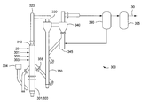
With reference to the figures, FIG. 1 depicts an illustrative system 100 for producing syngas utilizing a feedstock pretreatment process according to one or more embodiments described. In one or more embodiments, the system 100 for producing syngas includes one or more pretreatment systems 200, gasification systems 300, and recycle gas compression systems 400. Upon addition of a stream 10 containing raw feedstock (“raw feedstock stream”), each pretreatment system 200 can be used to release volatiles, remove moisture, increase porosity, increase reactivity, or any combination thereof, to provide a stream 20 containing the treated feedstock for gasification (“treated feedstock stream”). The treated feedstock stream 20 can be introduced to the one or more gasification systems 300 to provide one or more streams 30 containing syngas (“syngas stream”).
In one or more embodiments, at least a portion of the syngas stream 30 can be used to power one or more combustion turbines 500. The exhaust from the combustion turbines 500 can be directed to one or more heat recovery systems 650 and/or steam turbines 600.
The combustion turbines 500 and/or heat recovery systems 650 can generate carbon dioxide. The carbon dioxide can be recycled to the one or more gas compression systems 400 via stream 50. The carbon dioxide from stream 50 can be purified, compressed and heated or cooled to supercritical conditions within the compression system 400 unit operation area, and returned to the pretreatment system 200 via stream 40 (“supercritical carbon dioxide stream”). In one or more embodiments, at least a portion of stream 40 can be directed to the combustion turbines 500 and/or heat recovery systems 650.
The term “feedstock” as used herein refers to a raw material, whether solid, gas or liquid, used to produce a syngas. For example, the feedstock can include one or more carbonaceous materials. Illustrative carbonaceous materials include but are not limited to biomass (i.e, plant and/or animal matter or plant and/or animal derived matter); coal (high-sodium and low-sodium lignite, subbituminous, and/or anthracite for example); oil shale; coke; tar; heavy oil; and asphalt. The carbonaceous materials can be combined with hydrocarbon-based polymeric materials such as thermoplastics, elastomers and rubbers, polypropylenes, polyethylenes, polystyrenes, including copolymers and blends thereof; heavy hydrocarbon sludge and bottoms products from petroleum refineries and petrochemical plants; derivatives thereof; and mixtures and combinations thereof.
In one or more embodiments above or elsewhere herein, the feedstock can include a mixture or combination of one or more carbonaceous materials such as low ash or no ash polymer, biomass derived material, or by-product derived from manufacturing operations or produced as a result of governmental mandates to dispose of previously manufactured materials. For example, the feedstock can include one or more carbonaceous materials combined with one or more discarded consumer products such as carpet and/or car parts such as bumpers and dashboards. In one or more embodiments above or elsewhere herein, the feedstock can include recycled plastics such as polypropylene.
In one or more embodiments above or elsewhere herein, the feedstock can include a dry feed used for high moisture fuels such as subbituminous coal and lignite. In one or more embodiments above or elsewhere herein, the feedstock can be dried, and then pulverized by milling units such as one or more parallel bowl mills prior to feeding to the pretreatment system 200.
In one or more embodiments above or elsewhere herein, the feedstock can have an average particle diameter size from the range of about 50 μm to about 500 μm or from about 50 μm to about 400 μm. In one or more embodiments above or elsewhere herein, the average particle diameter size of the feedstock can be in the range of from about 150 μm to about 450 μm or from about 200 μm to about 400 μm.
Considering the pretreatment system 200 in more detail, FIG. 2 depicts an illustrative system 200 for pretreating a feedstock according to one or more embodiments described. The pretreatment system 200 can include one or more lock hoppers 210, intermediate vessels 220, and flow control valves 230. In one or more embodiments, the system 200 can include one or more lockhoppers 210, intermediate vessels 220, and flow control valves 230 arranged in parallel or series. For example, two lock hoppers 210 (first lockhopper and second lockhopper) with accompanying flow control valves 230 (first flow valve and second flow valve) can be arranged around a single intermediate vessel 220 in series as depicted.
The system 200 can allow for crushed feedstock via stream 10 to be loaded in the first lockhopper 210 and pressurized by an inert gas. The pressurized feedstock can then be transferred through the first flow valve 230 into the intermediate vessel 220 by gravity via one or more feeder lines suitable in the art for the system described. The pressure in the intermediate vessel 220 can be raised. Feedstock in the intermediate vessel 220 can be transferred into the second lockhopper 210 by gravity via one or more feeder lines suitable in the art. Treated feedstock via stream 20 can exit the second lockhopper 210 through a second flow valve 230 prior to entry into a nozzle 250. The nozzle 250 can facilitate feedstock entry into the gasification system 300. Flow control valves 230 can be of several types suitable in the art, including but not limited to rotary valves, screw feeders, and/or rotating disc valves.
In one or more embodiments, the intermediate vessel 210 and the second lockhopper 210 can be in pressure equilibrium. Alternatively, in one or more embodiments, a valve (not shown) below the intermediate vessel 220 can be closed, thus neutralizing the pressure of the first lockhopper 210 and the intermediate vessel 220 from the rest of the series ahead of the intermediate vessel 220. The cycle of transferring and pressurizing feedstock from the intermediate vessel 220 can be repeated such that the feedstock flow from the second lockhopper 210 and second flow valve 230 can continuously feed treated feedstock via stream 20 to the nozzle 250 and gasification system 300.
In one or more embodiments, the raw feedstock via stream 10 can be mixed with supercritical carbon dioxide within the intermediate vessel 220 in lieu of an inert gas. The supercritical carbon dioxide can be provided via stream 40. During start-up, carbon dioxide can be sourced from purchased tanks to fill in the inventory as most of it can be recycled, carbon dioxide can be routed from other combustion units in the complex such as other energy sources, or nitrogen can be used.
In one or more embodiments above or elsewhere herein, the intermediate vessels 220 can be pressurized with the supercritical carbon dioxide. For example, the supercritical carbon dioxide can be used to increase the pressure within the intermediate vessels 220 to a pressure of approximately above 73.8 bar.
Referring now to FIGS. 1 and 2, supercritical carbon dioxide can be recycled via stream 40 from the one or more compression systems 400 to increase the pressure of the intermediate vessel 220 from about atmospheric to above the critical pressure of carbon dioxide. The temperature in the intermediate vessel 220 can be above or below the critical temperature of carbon dioxide. In one or more embodiments it can be desirable to have the temperature of the intermediate vessel 220 above the critical temperature of the carbon dioxide so that the fluid in the intermediate vessel 220 can be supercritical, thereby increasing feedstock residence time and release of hydrocarbons from the feedstock. In one or more embodiments it can be desirable to have the temperature in the intermediate vessel 220 below the critical temperature of carbon dioxide to reduce the vessel size because the residence time requirement for release of hydrocarbons may be extremely small and can be accomplished in the second hopper 210 or in the transfer to the gasification system 300.
In one or more embodiments above or elsewhere herein, the supercritical carbon dioxide can provide significant improvements to the feedstock feed, including but not limited to volatiles extraction, porosity, reactivity, and reduction of particle size for better syngas quality. The supercritical carbon dioxide can also increase carbon conversion, yielding higher quality syngas. For gasifier reactors it can be imperative that feedstock be prepared such that the conversion of carbonaceous components of feedstock to high energy components of syngas can readily progress. The conversion of feedstock can be facilitated by making volatiles readily accessible in the gasifier, increasing the surface area of feedstock particles by increasing porosity and reducing particle diameter. Also, the use of inert material to convey the coal to the reactor can result in the syngas having lower energy content per unit mass. In one or more embodiments, the use of carbon dioxide also can act as a source of oxidizing material for the gasification of feedstock in the gasifier, thus reducing the requirement of oxygen or an air separation unit, and reducing the inert content in the produced syngas.
Although the foregoing has been described with reference to supercritical carbon dioxide, it is believed that any supercritical fluid can be used. Supercritical fluids can be regarded as “hybrid solvents” with properties between those of gases and liquids, i.e. a solvent with a low viscosity, high diffusion rates and low surface tension. In the case of supercritical carbon dioxide, the viscosity can be in the range of about 20 μPa·s to about 100 μPa·s (about 0.02 cP to about 0.1 cP). In comparison, liquids have viscosities of approximately 500 μPa·s to approximately 1000 μPa·s (approximately 0.5 cP to approximately 1.0 cP) and gases approximately 10 μPa·s (approximately 0.01 cP). Diffusivities of solutes in supercritical carbon dioxide can be up to a factor of about 10 times higher than that in liquid solvents. These properties can be strongly pressure dependent in the vicinity of the critical point, making supercritical carbon dioxide a highly tunable solvent. Supercritical carbon dioxide can extract a substantial amount of volatiles from feedstock, increase feedstock porosity, and improve gasifier reactivity.
The higher density of supercritical dioxide can decrease leakage across the flow valves 230 in the pretreatment system 200 resulting in increased reliability of the pretreatment or feed system. The leakage rate across the flow valves 230 can be inversely proportional to the density of the gas passing therethrough. For example, liquid material can pack across a flow valve better than a gas material because the liquid material has a higher density than the gas material. Though supercritical carbon dioxide gas cannot be as dense as a liquid, the density of supercritical carbon dioxide can be greater than that of a gas. Supercritical carbon dioxide (at pressures above about 1100 psig) can have about three times higher density than compressed carbon dioxide (at pressures of about 500 psig). Supercritical carbon dioxide can have substantially higher density compared to nitrogen. The substantially higher density of supercritical carbon dioxide can thus increase the efficiency of the flow valves 230 in the pretreatment system 200.
In one or more gasifier embodiments, the expansion of the supercritical carbon dioxide in the gasification system 300 can accelerate feedstock particles to mix with inert solids. Intimate mixing of feedstock particles with a heat source can be beneficial for the gasification system 300 operating in a short residence time mode.
Upon depressurization across the nozzle 250 and upon heating inside the gasification system 300, the supercritical carbon dioxide volume can rapidly expand to below supercritical levels and cause an increase in feedstock velocity. Across the nozzle 250, supercritical carbon dioxide can thus have substantially more volume expansion, and an increase in feedstock velocity than that of a similar volume of nitrogen resulting in a higher momentum for the feedstock to be better distributed in the reactor. In one or more embodiments, the nozzle 250 can be designed to maximize the acceleration of feedstock particles to penetrate a moving bed in a riser and improve mixing zone performance.
The pretreatment with supercritical carbon dioxide can allow the use of a wider array of raw feedstock, including coals with volatiles and coals that retain the volatiles by strong adsorption. The relatively low temperature of the supercritical carbon dioxide, beginning at about the critical temperature of 31.1° C., and the stability of carbon dioxide can allow most compounds to be extracted with little solvent reactivity, feedstock damage, and feedstock denaturing. In one or more embodiments, the rapid expansion by depressurization and heating of the supercritical carbon dioxide in the gasification system 300 can stabilize the solids in the gasifier reactor.
Use of supercritical carbon dioxide in the pretreatment system 200 can improve reliability of the feed system to the gasification system 300. Utilizing the feedstock pretreatment system 200 with supercritical carbon dioxide can substantially decrease feedstock bound volatile content and improve performance of the lock hoppers 210, intermediate vessels 220, rotary valves 230, feed lines, and nozzles 250 of the pretreatment system 200. The supercritical carbon dioxide can also be a promising green solvent because it can be non-toxic and efficiently recycled as a byproduct from gasification.
Considering the gasification system 300 in more detail, FIG. 3 depicts an illustrative system 300 for gasifying a feedstock according to one or more embodiments described. In one or more embodiments, the gasification system 300 can include a single reactor unit having one or more mixing zones 310, risers 320, disengagers 330 and cyclones 340. The solid particulates from the reactor can at least partially be removed from the syngas within one or more disengagers 330, cyclones 340, and/or particulate removal systems 390. The separated syngas can then be cooled and cleaned to remove contaminants including one or more sulfur-containing compounds within one or more gas cleanup systems 395.
The gasification system 300 can also include two or more reactor units arranged in series or parallel. Each reactor unit can be configured independent from the others or configured where any of the one or more mixing zones 310, risers 320, disengagers 330, and/or cyclones 340 can be shared. For simplicity and ease of description, embodiments of the invention will be further described in the context of a single reactor unit.
The treated feedstock stream 20, oxidant, and water are combined to produce a raw syngas. The oxidant can be introduced via stream 301 (“oxidant stream”). The water can be introduced via stream 303 (“water stream”).
The one or more oxidants can include air, oxygen, essentially oxygen, oxygen-enriched air, mixtures of oxygen and air, mixtures of oxygen and gas, mixtures of oxygen and inert gas such as nitrogen or argon, and the like. In one or more embodiments above or elsewhere herein, the one or more oxidants can be introduced into the mixing zone 310 at a rate suitable to control the temperature of the mixing zone 310. In one or more embodiments above or elsewhere herein, a molar ratio of oxygen to carbon in the recycled particles can be maintained at a substoichiometric proportion to promote the formation of carbon monoxide over carbon dioxide in the mixing zone 310. Thus, in one or more embodiments, the oxygen supplied via the oxidant to the mixing zone 310 can be less than about five percent of the stoichiometric amount of oxygen required for complete combustion of all the carbon supplied (whether from coal, polymer and/or biomass waste) to the mixing zone 310.
One or more treated feedstocks via stream 20 and one or more oxidants via stream 301 can be combined in the mixing zone 310. One or more sorbents via stream 302 (“sorbent stream”) can also be used. In one or more embodiments above or elsewhere herein, the sorbent stream 302 can be optionally admixed with the treated feedstock stream 20 to adsorb or consume significant errant oxygen entering the mixing zone 310 at a rate and level sufficient to delay or prevent the errant oxygen from reaching a concentration that results in undesirable reactions with hydrogen. The treated feedstock stream 20 and sorbent stream 302 can be mixed and fed together, or they can be fed separately to the mixing zone 310. The one or more treated feedstock streams 20, oxidant streams 301 and optional sorbent streams 302 can be injected sequentially or simultaneously.
In one or more embodiments, the one or more oxidants via stream 301 and water via stream 303 can be introduced at the bottom of the mixing zone 310, operating at up to about 285 psig and about 1800 F, to raise heat by burning the carbon in the recirculated solids (“char”). The treated feedstock stream 20 and optional sorbent stream 302 can be fed to the top of the mixing zone 310 to separate the treated feedstock from the oxidant and avoid burning the volatile material produced when the feedstock is heated. The solids and gases can be carried from the mixing zone 310 into the riser 320 where devolatilization and carbon-steam gasification reactions can occur. In one or more embodiments, at least a portion of the sulfur released from the coal can be captured as calcium sulfide by the calcium in the treated feedstock or by the added calcium-based sorbent.
The gas with entrained solids moves up through the mixing zone 310 into the riser 320 (which can have a slightly smaller diameter). The gas exits the riser 320 to enter the one or more disengagers 330 where the larger particles in the gas stream are removed by gravity separation. The remaining particles can be removed in the one or more cyclones 340. In one or more embodiments, the gas can exit the cyclones 340 and enter the one or more particulate removal systems 390 for further particulate removal.
As mentioned, the unreacted char and sorbent-derived material leaving the riser 330 can be captured by the disengager 330 and cyclone 340 and recycled to the mixing zone 310 through the loopseal 345, standpipe 350, and/or j-leg 355. The j-leg 355 can be a nonmechanical “j-valve.” Non-mechanical “y-valves” or “L-valves” can also be used. This recycling increases the effective solids residence time, increases the carbon conversion, and improves sorbent utilization.
Considering the riser 320 in more detail, the gas with entrained solids from the mixing zone 310 can enter the riser 320 where additional residence time allows char gasification, methane/steam reforming, water-shift and/or sulfur capture reactions to occur. In one or more embodiments above or elsewhere herein, the gas velocity in the riser 320 ranges from about 3 m/s to about 28 m/s, from about 6 m/s to about 25 m/s, from about 9 m/s to about 22 m/s, from about 10 m/s to about 20 m/s, or from about 9 m/s to about 15 m/s. In one or more embodiments above or elsewhere herein, the residence time and high temperature conditions in the riser 320 can provide for a water-shift reaction to reach equilibrium.
In one or more embodiments above or elsewhere herein, the mixing zone 310 can be operated at a moderate temperature as low as about 788° C. (1450° F.). In one or more embodiments above or elsewhere herein, the gasifier reactor can be operated in a temperature range of from about 1050° F. to about 1900° F., from about 1540° F. to about 1710° F., or at a suitable temperature below that which would melt the ash.
Heat can be supplied by a startup burner 304 burning the carbon in the recirculated solids in the lower part of the mixing zone 310 before recirculated solids contact the entering feedstock. Startup (i.e. prior to feeding the feedstock to the mixing zone 310) can be commenced by bringing the mixing zone 310 to a temperature of from about 950° F. to about 1200° F. and optionally feeding coke breeze or the equivalent to the mixing zone 310 to raise the temperature to about 1650° F.
In one or more embodiments, the operating temperature of the mixing zone 310 ranges from a low of about 500° F., 750° F., or 1000° F. to a high of about 1200° F., 1500° F., or 1800° F. In one or more embodiments above or elsewhere herein, the operating temperature of the mixing zone 310 ranges from about 700° F. to about 1750° F., from about 900° F. to about 1600° F., or from about 1200° F. to about 1600° F.
In one or more embodiments above or elsewhere herein, the operating temperature can be controlled by the recirculation rate of the solids, optional heat removal from the ash prior to entering the mixing zone 310, and oxidant 301 supply to the mixing zone 310. Excess oxygen in the air can be consumed by the recirculating solids forming primarily carbon dioxide, thereby minimizing tar formation and stabilizing reactor temperature during operation and periods of feed interruption, if any. The recirculating solids also can serve to rapidly heat the incoming feedstock and minimize tar formation.
In one or more embodiments above or elsewhere herein, the mixing zone 310 can be operated at pressures from about 0 psig to about 700 psig to increase thermal output per unit reactor cross-sectional area and enhance energy output in the subsequent power cycle. In one or more embodiments above or elsewhere herein, the mixing zone 310 can be operated at pressures from about 100 psig to about 650 psig, from about 100 psig to about 600 psig, or from about 100 psig to about 550 psig.
Considering the one or more particulate removal systems 390 in more detail, the one or more particulate removal systems 390 can include one or more coolers for cooling the syngas. In one or more embodiments above or elsewhere herein, the particulate removal systems 390 can include additional disengagers 330 and cyclones 340 which are known in the art for solids removal. In one or more embodiments above or elsewhere herein, the particulate removal systems 390 can include one or more particulate control devices (“PCD”). One or more sintered metal filters, metal filter candles, and/or ceramic filter candles (for example, iron aluminide filter material) can be used as a PCD.
Considering the one or more gas cleanup systems 395 in more detail, the one or more gas cleanup systems 395 can include one or more coolers for cooling the syngas. The gas cleanup systems 395 can include water quench, radiant and convective coolers, chemical quench and gas recycle quench to cool the syngas. In one or more embodiments, the gas cleanup system 395 can further include one or more primary coolers (not shown) or syngas heat recovery systems (not shown). The primary cooler or syngas heat recovery system can be used to recover heat from the high-temperature gasifier operation. Heat recovery can reclaim 5 to 25 percent of the energy in the feed depending on the process conditions. In one or more embodiments above or elsewhere herein, the raw syngas leaving the gasifier reactor flows to the heat recovery system where the syngas can be cooled by radiant and/or convective exchange. In one or more embodiments, the raw syngas can be cooled by a direct quench system, wherein water or cool recycle gas is injected into the hot raw syngas. The syngas can then pass through a series of heat exchangers for recovery of heat utilized for steam generation or process heating.
The one or more gas cleanup systems 395 can also include one or more processes to remove sulfur and other contaminants from the synthesis gas. Such processes for removing sulfur can include, but are not limited to, the use of zinc titanate, zinc ferite, tin oxide, zinc oxide, iron oxide, copper oxide, cerium oxide or mixtures thereof as well as the Selexol™ process, and the Sulfinol® Gas Treatment Process. The one or more gas cleanup systems can also be or include the CrystaSulf® H2S adsorber. In one or more embodiments above or elsewhere herein, mercury is removed using a bed of sulfur-impregnated activated carbon.
In one or more embodiments above or elsewhere herein, the syngas stream 30 produced in the gasification system 300 includes carbon monoxide, hydrogen, oxygen, hydrocarbons, sulfur, and solids. In one or more embodiments above or elsewhere herein, the syngas stream 30 produced in the gasification system 300 can be nearly nitrogen-free. In one or more embodiments above or elsewhere herein, the process converts at least about 85%, 90%, 95%, 98%, or 99% of the carbon from the treated feedstock to syngas.
Referring again to FIG. 1, the recycled carbon dioxide stream 50 from the overall process 100 can be compressed and heated above the critical pressure (Pc) and critical temperature (Tc) through one or more gas compression systems 400 to provide a supercritical carbon dioxide stream 40, which is recycled to the front end of the process 100 at the one or more pretreatment systems 200. Considering the gas compression systems 400 in more detail, any gas compressor (not shown) and amount of heat suitable for the operating conditions described can be used. In one or more embodiments above or elsewhere herein, the gas compression systems 400 can further include coupling with one or more gas turbines 500, steam turbines 600, and/or heat recovery systems 650.
In one or more embodiments above or elsewhere herein, the process 100 can include a combined cycle system, for example a Brayton cycle and a Carnot cycle, for power generation, wherein gaseous fuel from the syngas stream 30 can be combined with oxygen-bearing gas, combusted at a combustor (not shown), and fed to one or more combustion gas turbines 500 to generate electrical and/or mechanical energy via a generator. The hot exhaust gases from the combustion turbine 500 can be fed to one or more heat recovery steam generator systems 650 wherein a fraction of the thermal energy in the hot exhaust gases can be recovered as steam. The heat recovery steam generator 650 can be a dual-pressure unit with single reheat having a main steam pressure of about 1800 psia. The steam from the one or more of the heat recovery systems 650 along with any steam generated in other units of the process 100 can be fed to one or more steam turbines 600 to generate electrical or mechanical energy via one or more generators before rejecting any remaining low level heat in the turbine exhaust to a condensation medium. Other suitable embodiments can include humid air turbine cycles and the Tophat cycle. The recycled carbon dioxide stream 50 generated from the combustor in the combustion turbines 500 and heat recovery systems 650 along with carbon dioxide generated from other sections of the process 100 can be recycled to one or more gas compression systems 400.
Any one or more of the described embodiments may be combined with another. The gasification process described provides an excellent balance in flexibility, efficiency and safety with low to no emissions. The process in various embodiments operates at significantly higher circulation rates, velocities, and solvent densities compared to other pretreatment methods. This results in higher throughput, better mixing, and increased mass and transfer rates. The pretreatment system and method for gasification also include high carbon conversion due to excellent gas/solids contact, low water consumption, high percentage carbon dioxide recirculation, high volatile capture, high throughput, and high heat release rates that contribute to a small footprint as well as a simple mechanical design.
Specific embodiments can further include methods for pretreating feedstock for gasification comprising: combining a coal based feedstock stream and supercritical carbon dioxide stream within a pretreatment system to provide a treated feedstock stream; passing at least a portion of the treated feedstock stream to a gasifier to produce a synthesis gas stream comprising less than 50% by volume carbon dioxide, at least 5% by volume carbon monoxide and at least 1% by volume hydrogen; combusting at least a portion of the synthesis gas stream to form an exhaust stream comprising carbon dioxide; compressing at least a portion of the gasification byproduct stream to produce supercritical carbon dioxide; and recycling at least a portion of the supercritical carbon dioxide to the pretreatment system.
Specific embodiments can further include the methods of paragraph [0056] and one or more of the following embodiments: wherein the coal based feedstock stream comprises feedstock having an average particle size ranging from 150 μm to 450 μm; wherein the coal based feedstock is selected from the group consisting of high-sodium lignite, low-sodium lignite, subbituminous, bituminous and anthracite; wherein the supercritical carbon dioxide is combined with the feedstock stream in an amount sufficient to increase distribution of the feedstock to the gasifier; wherein the coal based feedstock stream and supercritical carbon dioxide stream are mixed within an intermediate vessel of a lockhopper in the pretreatment system; and/or wherein the coal based feedstock within the intermediate vessel of the lockhopper is pressurized using the supercritical carbon dioxide.
Specific embodiments can further include methods for pretreating feedstock for gasification comprising: mixing a coal based feedstock with supercritical carbon dioxide to increase the volatile content of the feedstock; passing at least a portion of the feedstock to a gasifier to produce a synthesis gas; combusting at least a portion of the synthesis gas to form an exhaust gas comprising carbon dioxide; compressing and heating the carbon dioxide to produce supercritical carbon dioxide; and recycling at least a portion of the supercritical carbon dioxide to the feedstock prior to the gasifier.
Specific embodiments can further include the methods of paragraph [0058] and one or more of the following embodiments: wherein the coal based feedstock stream comprises feedstock having an average particle size ranging from 150 μm to 450 μm; wherein the coal based feedstock is selected from the group consisting of high-sodium lignite, low-sodium lignite, subbituminous, bituminous and anthracite; wherein the carbon dioxide is an exhaust gas from one or more combustion turbines; wherein the coupling provides an additional carbon dioxide stream; and/or further including coupling the compression of carbon dioxide with the combustion of the synthesis gas stream.
Specific embodiments can further include systems for gasification comprising: a feedstock pretreatment unit comprising one or more lockhoppers, one or more intermediate vessels, and one or more rotary valves, wherein a feedstock to be treated is contacted with supercritical carbon dioxide within the one or more intermediate vessels to provide a treated feedstock; a gasification unit comprising one or more gasifiers; a compression unit; and a combustion turbine, wherein the rotary valves pass the treated feedstock to the gasification unit, and the supercritical carbon dioxide decreases leakage across the rotary valves.
Specific embodiments can further include the systems of paragraph [0060] and one or more of the following embodiments: further including at least one heat recovery system; wherein the gasification unit produces a synthesis gas that can be combusted within the one or more combustion turbines forming an exhaust gas comprising carbon dioxide; wherein the compression unit compresses and heats the carbon dioxide to supercritical conditions; wherein the intermediate vessel is disposed within the lockhopper; wherein the intermediate vessel is pressurized using the supercritical carbon dioxide; wherein the supercritical carbon dioxide is contacted with the feedstock stream in an amount sufficient to increase distribution of the feedstock to the gasifier; and/or wherein the supercritical carbon dioxide is mixed with the feedstock stream in an amount sufficient to increase distribution of the feedstock to the gasifier.
Certain embodiments and features have been described using a set of numerical upper limits and a set of numerical lower limits. It should be appreciated that ranges from any lower limit to any upper limit are contemplated unless otherwise indicated. Certain lower limits, upper limits and ranges appear in one or more claims below. All numerical values are “about” or “approximately” the indicated value, and take into account experimental error and variations that would be expected by a person having ordinary skill in the art.
Various terms have been defined above. To the extent a term used in a claim is not defined above, it should be given the broadest definition persons in the pertinent art have given that term as reflected in at least one printed publication or issued patent. Furthermore, all patents, test procedures, and other documents cited in this application are fully incorporated by reference to the extent such disclosure is not inconsistent with this application and for all jurisdictions in which such incorporation is permitted.
While the foregoing is directed to embodiments, other and further embodiments may be devised without departing from the basic scope thereof, and the scope thereof is determined by the claims that follow.

Claims (16)

What is claimed is:
1. A method for pretreating feedstock for gasification comprising:
combining a coal based feedstock and supercritical carbon dioxide within a pretreatment system to provide a treated feedstock;
passing at least a portion of the treated feedstock to a gasifier to produce a synthesis gas comprising less than 50% by volume carbon dioxide, at least 5% by volume carbon monoxide and at least 1% by volume hydrogen;
combusting at least a portion of the synthesis gas comprising less than 50% by volume carbon dioxide to form an exhaust gas comprising carbon dioxide;
compressing at least a portion of the exhaust gas to produce compressed carbon dioxide; and
recycling at least a portion of the compressed carbon dioxide at supercritical conditions to the pretreatment system.
2. The method of claim 1 wherein the coal based feedstock comprises feedstock having an average particle size ranging from 150 μm to 450 μm.
3. The method of claim 1 wherein the coal based feedstock is selected from the group consisting of high-sodium lignite, low-sodium lignite, subbituminous, bituminous and anthracite.
4. The method of claim 1 wherein the supercritical carbon dioxide is combined with the feedstock in an amount sufficient to increase distribution of the feedstock to the gasifier.
5. The method of claim 1 wherein the coal based feedstock and supercritical carbon dioxide are mixed within an intermediate vessel of a lockhopper in the pretreatment system.
6. The method of claim 5 wherein the coal based feedstock within the intermediate vessel of the lockhopper is pressurized using the supercritical carbon dioxide.
7. The method of claim 1, further comprising introducing one or more oxidants to the gasifier, wherein the one or more oxidants is present in an amount less than about 5% of the stoichiometric amount of oxygen required for complete combustion of all the carbon dioxide introduced to the gasifier.
8. The method of claim 7, wherein the coal based feedstock comprises one or more polymeric materials.
9. The method of claim 8, wherein the one or more polymeric materials comprise polypropylene, polyethylene, polystyrene, copolymers thereof, blends thereof, or any combination thereof.
10. A method for pretreating feedstock for gasification comprising:
mixing a coal based feedstock with supercritical carbon dioxide to increase the volatile content of the feedstock;
passing at least a portion of the feedstock to a gasifier to produce a synthesis gas;
combusting at least a portion of the synthesis gas comprising less than 50% by volume carbon dioxide to form an exhaust gas comprising carbon dioxide;
purifying, compressing, and heating the carbon dioxide to produce a compressed carbon dioxide at supercritical conditions; and
recycling at least a portion of the supercritical carbon dioxide at to the feedstock prior to the gasifier.
11. The method of claim 10 wherein the coal based feedstock comprises feedstock having an average particle size ranging from 150 μm to 450 μm.
12. The method of claim 10 wherein the coal based feedstock is selected from the group consisting of high-sodium lignite, low-sodium lignite, subbituminous, bituminous and anthracite.
13. The method of claim 10 wherein the exhaust gas is from one or more combustion turbines.
14. The method of claim 10, further comprising coupling the compression of the carbon dioxide with the combustion of the synthesis gas.
15. The method of claim 14, wherein the coupling provides additional carbon dioxide.
16. The method of claim 10, wherein the supercritical carbon dioxide is mixed with the feedstock in an amount sufficient to increase distribution of the feedstock to the gasifier.
US11/646,685 2006-12-28 2006-12-28 Methods for feedstock pretreatment and transport to gasification Active 2033-07-27 US8888875B2 (en)

Priority Applications (2)

Application Number Priority Date Filing Date Title
US11/646,685 US8888875B2 (en) 2006-12-28 2006-12-28 Methods for feedstock pretreatment and transport to gasification
PCT/US2007/025023 WO2008082460A1 (en) 2006-12-28 2007-12-06 Methods for feedstock pretreatment and transport to gasification

Applications Claiming Priority (1)

Application Number Priority Date Filing Date Title
US11/646,685 US8888875B2 (en) 2006-12-28 2006-12-28 Methods for feedstock pretreatment and transport to gasification

Publications (2)

Publication Number Publication Date
US20080155899A1 US20080155899A1 (en) 2008-07-03
US8888875B2 true US8888875B2 (en) 2014-11-18

Family

ID=39581975

Family Applications (1)

Application Number Title Priority Date Filing Date
US11/646,685 Active 2033-07-27 US8888875B2 (en) 2006-12-28 2006-12-28 Methods for feedstock pretreatment and transport to gasification

Country Status (2)

Country Link
US (1) US8888875B2 (en)
WO (1) WO2008082460A1 (en)

Cited By (1)

* Cited by examiner, † Cited by third party
Publication number Priority date Publication date Assignee Title
US20120216680A1 (en) * 2011-02-25 2012-08-30 Southern Company Dispersed Bubble Reactor For Enhanced Gas-Liquid-Solids Contact And Mass Transfer

Families Citing this family (25)

* Cited by examiner, † Cited by third party
Publication number Priority date Publication date Assignee Title
DE102007020333A1 (en) * 2007-04-30 2008-11-06 Siemens Ag Use of pure carbon dioxide as an inerting and conveying medium in dust injection systems for pulverized coal gasification
DE102009036973A1 (en) * 2009-08-12 2011-02-17 Uhde Gmbh Method for supplying an entrained flow gasification reactor with carbonaceous fuels
US20110220846A1 (en) * 2010-01-14 2011-09-15 Banowetz Gary M Non-densified biomass gasification method and apparatus
DE102010026793B4 (en) * 2010-07-10 2012-04-26 Messer Group Gmbh Method and apparatus for supplying an oxyfuel power plant with fuel
DE102010026792B4 (en) * 2010-07-10 2012-02-16 Messer Group Gmbh Method of operating an oxyfuel power plant
BR112013005131A2 (en) * 2010-09-01 2018-04-24 Starlight Energy Holdings LLC system and process for gasification of biomass products
US8636923B2 (en) * 2010-10-29 2014-01-28 Enerkem, Inc. Production of synthesis gas by heating oxidized biomass with a hot gas obtained from oxidation of residual products
US9133405B2 (en) 2010-12-30 2015-09-15 Kellogg Brown & Root Llc Systems and methods for gasifying a feedstock
CN102247823B (en) * 2011-04-29 2012-12-19 叶向荣 Preparation method of sulfurizing porous nanometer material for high-efficiency hydrargyrum removal
EP2715233B1 (en) * 2011-05-24 2019-01-02 Her Majesty The Queen In Right Of Canada As Represented By The Minister Of Natural Resources High pressure fossil fuel oxy-combustion system with carbon dioxide capture for interface with an energy conversion system
US10174265B2 (en) 2011-06-10 2019-01-08 Bharat Petroleum Corporation Limited Process for co-gasification of two or more carbonaceous feedstocks and apparatus thereof
GB2492097B (en) * 2011-06-21 2013-06-12 Chinook End Stage Recycling Ltd Improvements in material processing
US9388980B2 (en) 2011-12-15 2016-07-12 Kellogg Brown + Root LLC Systems and methods for gasifying a hydrocarbon feedstock
US8888899B2 (en) 2012-04-12 2014-11-18 Kellogg Brown & Root Llc Transfer line for the primary cyclone of a gasifier
JP2014015499A (en) * 2012-07-06 2014-01-30 Hitachi Ltd Gasification method and system of the same, and coal gasification composite electricity generation method and system of the same
ITMI20130320A1 (en) * 2013-03-04 2014-09-05 Danilo Dante Bonfadini CONVERSION PLANT OF CARBONOUS MATRICES, PARTICULARLY FOR THE PRODUCTION OF ENERGY, AND ITS PROCEDURE.
US10144874B2 (en) * 2013-03-15 2018-12-04 Terrapower, Llc Method and system for performing thermochemical conversion of a carbonaceous feedstock to a reaction product
CN105163841A (en) * 2013-05-02 2015-12-16 英派尔科技开发有限公司 System and method for reducing corrosion in a reactor system using corrosion protection layers
US10364398B2 (en) * 2016-08-30 2019-07-30 Thermochem Recovery International, Inc. Method of producing product gas from multiple carbonaceous feedstock streams mixed with a reduced-pressure mixing gas
JP2020506983A (en) * 2017-01-15 2020-03-05 ウォームサー エナジー ソリューションズ,インコーポレーテッド Total steam gasification for supercritical CO2 power cycle system
CN110461810B (en) 2017-03-24 2022-05-13 泰拉能源公司 Method and system for recycling pyrolysis tail gas by conversion to formic acid
US10787610B2 (en) 2017-04-11 2020-09-29 Terrapower, Llc Flexible pyrolysis system and method
CN109441565A (en) * 2018-09-30 2019-03-08 东方电气集团东方汽轮机有限公司 A kind of steam turbine assembled unit and coal gasification systems
CN109988654A (en) * 2019-04-29 2019-07-09 西安交通大学 A kind of ciculation fluidized bed gasification system of supercritical water and method
CN114686267B (en) * 2022-03-22 2023-11-17 新奥科技发展有限公司 Conveying device and conveying method

Citations (34)

* Cited by examiner, † Cited by third party
Publication number Priority date Publication date Assignee Title
US4199327A (en) 1978-10-30 1980-04-22 Kaiser Engineers, Inc. Process for gasification of coal to maximize coal utilization and minimize quantity and ecological impact of waste products
US4230556A (en) 1978-12-15 1980-10-28 Gulf Oil Corporation Integrated coal liquefaction-gasification process
US4244706A (en) 1979-09-10 1981-01-13 The United States Of America As Represented By The United States Department Of Energy Process for gasifying carbonaceous material from a recycled condensate slurry
US4257806A (en) 1976-03-03 1981-03-24 Kobe Steel, Limited Fired iron-ore pellets having macro pores and process for producing the same
US4325709A (en) 1978-05-31 1982-04-20 Brennstoffinstitut Freiberg Method for the operation of gasification plants for pulverized fuels
US4391611A (en) 1981-03-05 1983-07-05 The United States Of America As Represented By The United States Department Of Energy Gasification system
US4493636A (en) 1981-03-05 1985-01-15 The United States Of America As Represented By The United States Department Of Energy Gasification system
US4765781A (en) * 1985-03-08 1988-08-23 Southwestern Public Service Company Coal slurry system
US5170727A (en) 1991-03-29 1992-12-15 Union Carbide Chemicals & Plastics Technology Corporation Supercritical fluids as diluents in combustion of liquid fuels and waste materials
US5361513A (en) 1992-11-25 1994-11-08 Amax Coal Industries, Inc. Method and apparatus for drying and briquetting coal
US5392594A (en) 1993-02-01 1995-02-28 Air Products And Chemicals, Inc. Integrated production of fuel gas and oxygenated organic compounds from synthesis gas
US5423894A (en) * 1993-05-03 1995-06-13 Texaco Inc. Partial oxidation of low rank coal
US5447702A (en) 1993-07-12 1995-09-05 The M. W. Kellogg Company Fluid bed desulfurization
US5560900A (en) 1994-09-13 1996-10-01 The M. W. Kellogg Company Transport partial oxidation method
US5656042A (en) * 1992-10-22 1997-08-12 Texaco Inc. Environmentally acceptable process for disposing of scrap plastic materials
US5655466A (en) 1992-10-08 1997-08-12 Imatran Voima Oy Method and configuration for facilitating the fuel feed into a pressurized space
US5685138A (en) 1995-02-09 1997-11-11 Fluor Corporation Integrated drying of feedstock feed to IGCC plant
US6054043A (en) 1995-03-28 2000-04-25 Simpson; Theodore B. Process for the hydrogenation of hydro-carbonaceous materials (Carb-Mat) for the production of vaporizable products
US20020077512A1 (en) 2000-12-20 2002-06-20 Tendick Rex Carl Hydrocarbon conversion system and method with a plurality of sources of compressed oxygen-containing gas
US6488728B1 (en) 1997-06-12 2002-12-03 Pac Holdings S.A. Method for the disposal of waste products containing hydrocarbons and/or halogenated waste products
US20030041518A1 (en) 2001-09-05 2003-03-06 Texaco Inc. Recycle of hydrogen from hydroprocessing purge gas
US20030046868A1 (en) * 2001-03-12 2003-03-13 Lewis Frederic Michael Generation of an ultra-superheated steam composition and gasification therewith
US20030131582A1 (en) 2001-12-03 2003-07-17 Anderson Roger E. Coal and syngas fueled power generation systems featuring zero atmospheric emissions
US6676716B2 (en) 1994-03-10 2004-01-13 Ebara Corporation Method and apparatus for treating wastes by gasification
WO2004065847A2 (en) 2003-01-16 2004-08-05 Alstom (Switzerland) Ltd Combustion installation with co2 recovery
US20040182000A1 (en) 2002-09-10 2004-09-23 Mansour Momtaz N. Steam reforming process and apparatus
US6802178B2 (en) 2002-09-12 2004-10-12 The Boeing Company Fluid injection and injection method
US20040221583A1 (en) 2003-05-08 2004-11-11 Roger Wylie Combined cycle for generating electric power
US20050167333A1 (en) 2004-01-30 2005-08-04 Mccall Thomas F. Supercritical Hydrocarbon Conversion Process
US20060096298A1 (en) 2004-11-10 2006-05-11 Barnicki Scott D Method for satisfying variable power demand
US20060149423A1 (en) 2004-11-10 2006-07-06 Barnicki Scott D Method for satisfying variable power demand
US20060248791A1 (en) 2004-05-03 2006-11-09 Hogsett Robert F Method and apparatus for thermally upgrading carbonaceous materials
US20070137107A1 (en) * 2005-12-19 2007-06-21 Barnicki Scott D Process for humidifying synthesis gas
US20070178035A1 (en) * 2006-02-01 2007-08-02 Vincent White Method of treating a gaseous mixture comprising hydrogen and carbon dioxide

Family Cites Families (2)

* Cited by examiner, † Cited by third party
Publication number Priority date Publication date Assignee Title
US6106595A (en) * 1996-04-30 2000-08-22 Spencer; Dwain F. Methods of selectively separating CO2 from a multicomponent gaseous stream
KR100643253B1 (en) * 1997-12-18 2006-11-13 가부시키가이샤 에바라 세이사꾸쇼 Gasification furnace

Patent Citations (38)

* Cited by examiner, † Cited by third party
Publication number Priority date Publication date Assignee Title
US4257806A (en) 1976-03-03 1981-03-24 Kobe Steel, Limited Fired iron-ore pellets having macro pores and process for producing the same
US4325709A (en) 1978-05-31 1982-04-20 Brennstoffinstitut Freiberg Method for the operation of gasification plants for pulverized fuels
US4199327A (en) 1978-10-30 1980-04-22 Kaiser Engineers, Inc. Process for gasification of coal to maximize coal utilization and minimize quantity and ecological impact of waste products
US4230556A (en) 1978-12-15 1980-10-28 Gulf Oil Corporation Integrated coal liquefaction-gasification process
US4244706A (en) 1979-09-10 1981-01-13 The United States Of America As Represented By The United States Department Of Energy Process for gasifying carbonaceous material from a recycled condensate slurry
US4391611A (en) 1981-03-05 1983-07-05 The United States Of America As Represented By The United States Department Of Energy Gasification system
US4493636A (en) 1981-03-05 1985-01-15 The United States Of America As Represented By The United States Department Of Energy Gasification system
US4765781A (en) * 1985-03-08 1988-08-23 Southwestern Public Service Company Coal slurry system
US5170727A (en) 1991-03-29 1992-12-15 Union Carbide Chemicals & Plastics Technology Corporation Supercritical fluids as diluents in combustion of liquid fuels and waste materials
US5655466A (en) 1992-10-08 1997-08-12 Imatran Voima Oy Method and configuration for facilitating the fuel feed into a pressurized space
US5656042A (en) * 1992-10-22 1997-08-12 Texaco Inc. Environmentally acceptable process for disposing of scrap plastic materials
US5361513A (en) 1992-11-25 1994-11-08 Amax Coal Industries, Inc. Method and apparatus for drying and briquetting coal
US5392594A (en) 1993-02-01 1995-02-28 Air Products And Chemicals, Inc. Integrated production of fuel gas and oxygenated organic compounds from synthesis gas
US5423894A (en) * 1993-05-03 1995-06-13 Texaco Inc. Partial oxidation of low rank coal
US5447702A (en) 1993-07-12 1995-09-05 The M. W. Kellogg Company Fluid bed desulfurization
US5578093A (en) 1993-07-12 1996-11-26 The M. W. Kellogg Company Fluid bed desulfurization
US6676716B2 (en) 1994-03-10 2004-01-13 Ebara Corporation Method and apparatus for treating wastes by gasification
US5560900A (en) 1994-09-13 1996-10-01 The M. W. Kellogg Company Transport partial oxidation method
US5953899A (en) 1995-02-09 1999-09-21 Fluor Daniel, Inc. Integrated drying of feedstock feed to integrated combined-cycle gasification plant
US5685138A (en) 1995-02-09 1997-11-11 Fluor Corporation Integrated drying of feedstock feed to IGCC plant
US6054043A (en) 1995-03-28 2000-04-25 Simpson; Theodore B. Process for the hydrogenation of hydro-carbonaceous materials (Carb-Mat) for the production of vaporizable products
US6488728B1 (en) 1997-06-12 2002-12-03 Pac Holdings S.A. Method for the disposal of waste products containing hydrocarbons and/or halogenated waste products
US20020077512A1 (en) 2000-12-20 2002-06-20 Tendick Rex Carl Hydrocarbon conversion system and method with a plurality of sources of compressed oxygen-containing gas
US20030046868A1 (en) * 2001-03-12 2003-03-13 Lewis Frederic Michael Generation of an ultra-superheated steam composition and gasification therewith
US20030041518A1 (en) 2001-09-05 2003-03-06 Texaco Inc. Recycle of hydrogen from hydroprocessing purge gas
US20030131582A1 (en) 2001-12-03 2003-07-17 Anderson Roger E. Coal and syngas fueled power generation systems featuring zero atmospheric emissions
US20040182000A1 (en) 2002-09-10 2004-09-23 Mansour Momtaz N. Steam reforming process and apparatus
US6802178B2 (en) 2002-09-12 2004-10-12 The Boeing Company Fluid injection and injection method
WO2004065847A2 (en) 2003-01-16 2004-08-05 Alstom (Switzerland) Ltd Combustion installation with co2 recovery
US20060130719A1 (en) 2003-01-16 2006-06-22 Jean-Xavier Morin Combustion installation with co2 recovery
US20040221583A1 (en) 2003-05-08 2004-11-11 Roger Wylie Combined cycle for generating electric power
US6966190B2 (en) 2003-05-08 2005-11-22 Wylie Inentions Co., Inc. Combined cycle for generating electric power
US20050167333A1 (en) 2004-01-30 2005-08-04 Mccall Thomas F. Supercritical Hydrocarbon Conversion Process
US20060248791A1 (en) 2004-05-03 2006-11-09 Hogsett Robert F Method and apparatus for thermally upgrading carbonaceous materials
US20060096298A1 (en) 2004-11-10 2006-05-11 Barnicki Scott D Method for satisfying variable power demand
US20060149423A1 (en) 2004-11-10 2006-07-06 Barnicki Scott D Method for satisfying variable power demand
US20070137107A1 (en) * 2005-12-19 2007-06-21 Barnicki Scott D Process for humidifying synthesis gas
US20070178035A1 (en) * 2006-02-01 2007-08-02 Vincent White Method of treating a gaseous mixture comprising hydrogen and carbon dioxide

Non-Patent Citations (11)

* Cited by examiner, † Cited by third party
Title
"Coal: America's Energy Future, vol. II: A Technical Overview" Report of the National Coal Council, Mar. 2006.
"PERP 03/04S11," Coal Gasification Technologies, Nexant Chem Systems, Jan. 2005, pp. 1-46.
Agarwal, A.T., "Improving Rotary Valve Performance," Chemical Eng., Mar. 2005, p. 29-33.
Alessi, P. et al., "Particle production of steroid drugs using supercritical fluid processing," I & EC Res., 35(12), p. 4718-4726.
Alessi, P., et al., "Particle production of steroid drugs using supercritical fluid processing," I&EC Res., 35(12), p. 4718-4726.
Barker, et al. "Pressure feeder for powered coal or other finely divided solids," I & EC, 43(5), p. 1204-1209.
Barker, et al., "Pressure feeder for powered coal or other finely divided solids," I & EC, 43(5), p. 1204-1209.
Campbell, William M., et al. "Transport Gasifier," U.S. Appl. No. 08/090,804.
Holt, Neville, "Gasification Process Selection-Trade-offs and Ironies," Electronic Power Research Institute Gasification Technologies Conference, Washington DC, Oct. 4-6, 2004.
Maurstad, Ola. "An Overview of Coal based Integrated Gasification Combined Cycle (IGCC) Technology," Massachusetts Institute for Technolgy-Laboratory for Energy and the Environment, Sep. 2005, MIT LFEE 2005-002 WP, pp. 1-36.
Maustad, Ola. "An Overview of Coal based Integrated Gasification Combined Cycle (IGCC) Technology," Massachusetts Institute for Technology-Laboratory for Energy and the Environment, Sep. 2005, MIT LFEE 2005-002 WP, pp. 1-36.

Cited By (2)

* Cited by examiner, † Cited by third party
Publication number Priority date Publication date Assignee Title
US20120216680A1 (en) * 2011-02-25 2012-08-30 Southern Company Dispersed Bubble Reactor For Enhanced Gas-Liquid-Solids Contact And Mass Transfer
US9242220B2 (en) * 2011-02-25 2016-01-26 Southern Company Dispersed bubble reactor for enhanced gas-liquid-solids contact and mass transfer

Also Published As

Publication number Publication date
WO2008082460A1 (en) 2008-07-10
US20080155899A1 (en) 2008-07-03

Similar Documents

Publication Publication Date Title
US8888875B2 (en) Methods for feedstock pretreatment and transport to gasification
US8221513B2 (en) Low oxygen carrier fluid with heating value for feed to transport gasification
CN108026459B (en) All-steam gasification with carbon capture
US9822318B2 (en) Systems and methods for oxidation of synthesis gas tar
US7722690B2 (en) Methods for producing synthesis gas
ES2804520T3 (en) Two-stage gasification with dual rapid cooling
JP2010024448A (en) Systems and methods for producing substitute natural gas
US9133405B2 (en) Systems and methods for gasifying a feedstock
JP2012522870A (en) Two-stage dry feed gasifier and method
EP0634470A1 (en) Transport gasifier
US20230151286A1 (en) Char Preparation System and Gasifier for All-Steam Gasification with Carbon Capture
US20150034876A9 (en) Systems And Methods For Producing Substitute Natural Gas
US9388980B2 (en) Systems and methods for gasifying a hydrocarbon feedstock
CN113348230A (en) Full steam gasification with solid fuel preparation system
KR20140080453A (en) Circulating Fluidized Bed Gasifier Equipped with Heat Exchanger Therein
US8540897B1 (en) Water quench for gasifier
AU2009330376A1 (en) Tar-free gasification system and process

Legal Events

Date Code Title Description
AS Assignment

Owner name: KELLOGG BROWN & ROOT LLC, TEXAS

Free format text: ASSIGNMENT OF ASSIGNORS INTEREST;ASSIGNOR:RAMAMURTHY, PRITHAM;REEL/FRAME:018750/0633

Effective date: 20061227

STCF Information on status: patent grant

Free format text: PATENTED CASE

AS Assignment

Owner name: BANK OF AMERICA, N.A., AS ADMINISTRATIVE AGENT, NORTH CAROLINA

Free format text: SECURITY INTEREST;ASSIGNOR:KELLOGG BROWN & ROOT LLC;REEL/FRAME:046022/0413

Effective date: 20180425

Owner name: BANK OF AMERICA, N.A., AS ADMINISTRATIVE AGENT, NO

Free format text: SECURITY INTEREST;ASSIGNOR:KELLOGG BROWN & ROOT LLC;REEL/FRAME:046022/0413

Effective date: 20180425

MAFP Maintenance fee payment

Free format text: PAYMENT OF MAINTENANCE FEE, 4TH YEAR, LARGE ENTITY (ORIGINAL EVENT CODE: M1551)

Year of fee payment: 4

MAFP Maintenance fee payment

Free format text: PAYMENT OF MAINTENANCE FEE, 8TH YEAR, LARGE ENTITY (ORIGINAL EVENT CODE: M1552); ENTITY STATUS OF PATENT OWNER: LARGE ENTITY

Year of fee payment: 8