US8890876B1 - Microprocessor including a display interface in the microprocessor - Google Patents
Microprocessor including a display interface in the microprocessor Download PDFInfo
- Publication number
- US8890876B1 US8890876B1 US11/963,603 US96360307A US8890876B1 US 8890876 B1 US8890876 B1 US 8890876B1 US 96360307 A US96360307 A US 96360307A US 8890876 B1 US8890876 B1 US 8890876B1
- Authority
- US
- United States
- Prior art keywords
- integrated circuit
- processing system
- graphics
- graphics engine
- processor core
- Prior art date
- Legal status (The legal status is an assumption and is not a legal conclusion. Google has not performed a legal analysis and makes no representation as to the accuracy of the status listed.)
- Active, expires
Links
Images


Classifications
-
- G—PHYSICS
- G06—COMPUTING; CALCULATING OR COUNTING
- G06F—ELECTRIC DIGITAL DATA PROCESSING
- G06F13/00—Interconnection of, or transfer of information or other signals between, memories, input/output devices or central processing units
- G06F13/38—Information transfer, e.g. on bus
- G06F13/382—Information transfer, e.g. on bus using universal interface adapter
- G06F13/385—Information transfer, e.g. on bus using universal interface adapter for adaptation of a particular data processing system to different peripheral devices
-
- Y—GENERAL TAGGING OF NEW TECHNOLOGICAL DEVELOPMENTS; GENERAL TAGGING OF CROSS-SECTIONAL TECHNOLOGIES SPANNING OVER SEVERAL SECTIONS OF THE IPC; TECHNICAL SUBJECTS COVERED BY FORMER USPC CROSS-REFERENCE ART COLLECTIONS [XRACs] AND DIGESTS
- Y02—TECHNOLOGIES OR APPLICATIONS FOR MITIGATION OR ADAPTATION AGAINST CLIMATE CHANGE
- Y02D—CLIMATE CHANGE MITIGATION TECHNOLOGIES IN INFORMATION AND COMMUNICATION TECHNOLOGIES [ICT], I.E. INFORMATION AND COMMUNICATION TECHNOLOGIES AIMING AT THE REDUCTION OF THEIR OWN ENERGY USE
- Y02D10/00—Energy efficient computing, e.g. low power processors, power management or thermal management
Definitions
- microprocessor systems with a local display device such as a liquid-crystal display may use a discrete graphics chip or an integrated graphics engine (commonly called a GPU) built into a core-logic chip such as a north bridge or south bridge.
- a graphics chip or an integrated graphics engine (commonly called a GPU) built into a core-logic chip such as a north bridge or south bridge.
- FIG. 1 is a diagram of a first conventional microprocessor system 10 .
- the microprocessor system 10 comprises a processor 12 coupled to a south bridge 14 .
- the processor 12 includes one or more processor cores 15 , a DRAM controller 16 , both of which are coupled to a bus 20 .
- the bus 20 is coupled to a first bus interface 22 .
- the DRAM controller 16 can be coupled to a DRAM 24 .
- the south bridge 14 communicates with the processor 12 , via a second bus interface 26 to the first bus interface 22 .
- the south bridge 14 includes a second bus 28 , which is coupled to a plurality of input-output (I/O) devices 30 - 40 .
- I/O input-output
- the second bus interface 26 communicates with a graphics engine external 42 to the south bridge 14 , which can be coupled to a display 44 and a second memory 46 .
- FIG. 2 is a second conventional microprocessor system 10 ′, in which similar elements have similar numbers to FIG. 1 .
- the integrated graphics engine 42 ′ is internal to the south bridge 14 ′ and is coupled to a display 44 ′.
- the integrated solution of FIG. 3 usually shares the system's main memory 24 ′ between the processor core 15 ′ and the graphics engine 42 ′, an approach known as Unified Memory Architecture (UMA).
- UMA Unified Memory Architecture
- the graphics engine 42 ′ has an associated display interface on the same chip, such as RGB or DVI so some systems have two interfaces when only one is needed.
- the integrated-graphics solution requires display refresh data to be transferred from the memory 24 to the processor core 15 via the memory bus, then from the processor 12 to the graphics engine 42 in the south bridge 14 via a front-side bus. This extra transfer wastes energy and reduces system performance by consuming some of the bandwidth of the front-side bus.
- FIG. 3 is a third conventional microprocessor system 10 ′′ in which similar elements have similar numbers as in FIG. 1 .
- the graphics engine 42 ′′ is part of the processor 12 ′′.
- a processing system comprises a first integrated circuit.
- the first integrated circuit includes a processor core, a display interface and memory controller coupled to a first bus interface.
- the display interface is adapted to display graphical information generated by a graphics engine.
- the graphics engine is not on the first integrated circuit.
- the processing system includes a second bus interface for allowing communication with the first integrated circuit via the first bus interface.
- the second bus interface is adapted to allow for communication to the graphics engine.
- FIG. 1 is a diagram of a first conventional microprocessor system.
- FIG. 2 is a second conventional microprocessor system.
- FIG. 3 is a third conventional microprocessor system.
- FIG. 4 is a diagram of an embodiment of a microprocessor system in accordance with the present invention.
- FIG. 5 illustrates the system of FIG. 4 in which the draw path and refresh path is shown.
- FIG. 6 has similar elements to that of FIG. 4 , except that the graphics engine is external to the south bridge, according to another embodiment of the present invention.
- FIG. 7 illustrates the system of FIG. 6 in which the contents of the currently active frame buffer copied from the dedicated graphics memory to main memory.
- FIG. 8 illustrates the system of FIG. 6 in which the graphics engine either put into a low-power configuration or powered off.
- the present invention relates generally to microprocessors and more particularly to an integrated display interface.
- the following description is presented to enable one of ordinary skill in the art to make and use the invention and is provided in the context of a patent application and its requirements.
- Various modifications to the preferred embodiments and the generic principles and features described herein will be readily apparent to those skilled in the art.
- the present invention is not intended to be limited to the embodiments shown, but is to be accorded the widest scope consistent with the principles and features described herein.
- HDL hardware description language
- Applicable HDLs include those at the layout, circuit netlist, register transfer, and/or schematic capture levels. Examples of HDLs include, but are not limited to: GDS II and OASIS (layout level); various SPICE languages, and IBIS (circuit netlist level); Verilog and VHDL (register transfer level); and Virtuoso custom design language and Design Architecture-IC custom design language (schematic capture level). HDL descriptions may also be used for a variety of purposes, including but not limited to layout, behavior, logic and circuit design verification, modeling, and/or simulation.
- a microprocessor system in accordance with the present invention addresses the above identified features of the present invention in more detail, refer to the following.
- a microprocessor includes memory interface and a display interface as well as the logic necessary to connect these two interfaces.
- the microprocessor package pinout could be made the same as a fully integrated product that includes a microprocessor, a memory interface, a graphics engine, and a display interface.
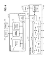
- FIG. 4 is a diagram of a first embodiment of a microprocessor system 100 in accordance with an embodiment of the present invention.
- the microprocessor system 100 comprises a processor 112 coupled to a south bridge 114 .
- the processor 112 includes one or more processor cores 115 , a DRAM controller 116 , both of which are coupled to a bus 120 .
- the system 100 includes an integrated display interface 148 which is coupled to a display 150 and to bus 120 .
- the bus 120 is coupled to a first bus interface 122 .
- the DRAM controller 116 coupled to a DRAM 124 .
- the south bridge 114 communicates with the processor 112 , via a second bus interface 126 to the first bus interface 122 .
- the south bridge 114 includes a second bus 128 , which is coupled to a plurality of input-output devices 130 - 138 .
- the bus interface 126 communicates with an internal graphics engine 142 , which can be coupled to a display 144 .
- the microprocessor system 100 could operate with a graphics engine 142 that has an interface to a display 144 or the system 100 could operate with a graphics engine 142 that does not have an interface to a display.
- the microprocessor system 100 includes one or more processor cores 115 , the display interface 148 which includes the necessary logic to support display-refresh operations and to display graphical information by a graphics engine, and the DRAM controller 116 including a memory interface.
- the logic to support display-refresh operations is often called a CRT controller function.
- the CRT controller function may be used with any type of display. Accordingly the CRT controller function is not limited to controlling a CRT but could control a LCD, OLED, LCOS, laser scanning or any other type of display.
- the CRT controller function is combined with the graphics engine 142 .
- the CRT controller function is separate from the graphics engine 142 typically as part of the display interface 148 .
- the CRT controller function may also perform compositing operations in which multiple graphical images are combined to generate an image for the display.
- Compositing is a known technique in computer graphics and is used in Microsoft's Windows Vista operating system.
- processor 112 could include a CRT controller function but not a graphics engine, or could include both a CRT controller function and a graphics engine but the graphics engine is disabled because a discrete graphics chip is present in the south bridge 114 .
- the processor or other component containing the display interface and CRT controller could also be equipped with all or part of a digital video decoding engine.
- a video engine can be much less complex than a high-end graphics engine, although in some implementations a graphics engine can perform video-decoding functions in software.
- the video-decoding functions are divided among the graphics engine and dedicated logic blocks, for example, when the graphics engine performs transport and stream demultiplexing plus video and audio decoding and dedicated logic performs color-space conversion and video scaling, the functions implemented in dedicated logic blocks would preferably be integrated into the processor or other component containing the display interface and CRT controller function.
- the CRT controller function is configured according to the requirements of the display device and the operating system.
- the graphics engine 142 performs graphics operations as required by the operating system and applications, and sets pointers in the CRT controller according to the location of the frame buffer(s) located in system main memory, graphics memory, or both. Alternately these pointers may be set by software running on the processor core 115 , especially for 2D-only display operations.
- FIG. 5 illustrates the system 100 of FIG. 4 in which the draw path 202 between DRAM 124 and the graphics engine 150 is shown.
- the CRT controller then fetches display data from the DRAM 124 and transmits it to the display 150 .
- FIG. 5 also shows the refresh path 204 between the DRAM 124 and the display device 150 .
- FIG. 6 has similar elements to that of FIG. 4 .
- the graphics engine 142 is external to the south bridge.
- a second memory 160 and a second display 144 are coupled to the graphics engine 142 .
- the display interface 148 can be configured to refresh the display device from a compressed or otherwise static frame buffer without further graphics engine 142 intervention. To enter this mode of operation, the contents of the currently active frame buffer are copied from the dedicated graphics memory (if present) to main memory, shown in FIG. 7 . During this mode of operation, the graphics engine 142 is not operating, so it can be put into a low-power configuration or powered off entirely as appropriate as illustrated in FIG. 8 .
- the graphics engine 142 can be put into a low-power configuration or powered off entirely and its functions can be taken over by the processor core 115 .
- This situation might arise if no application is currently performing any 3D rendering, since software running on a processor core 115 can perform 2D-only functions such as windows management.
- the basis for choosing between graphics engine 142 -based operation and processor core 115 -based operation could include whether the user will detect significant performance degradation due to processor core 115 -based operation and whether the processor core 115 can perform the necessary functions using less total power than the graphics engine 142 .
- An improved non-UMA implementation for high-end mobile systems in which the microprocessor includes the processor core 115 and display interface 148 , a discrete graphics chip includes the graphics engine 142 and a local graphics-memory interface, and the display 150 is connected to the display interface 148 as shown in FIG. 6 , but without the second display.
- microprocessor includes the processor core 115 and display interface 148 ;
- a discrete graphics chip includes the graphics engine 142 , a local graphics-memory interface, and a local display interface; and displays 150 and 144 are connected to the display interface 148 as well as the interface on the graphics engine 142 shown in FIG. 6 .
- microprocessor includes the processor core 115 and a display interface 148 that is not used; a discrete graphics chip includes the processor core 115 , a local graphics-memory interface, and a local display interface; and the display is connected to the display interface on the graphics chip of FIG. 6 , when the first display 150 is not used.
- a system and method in accordance with the present invention thus allows the microprocessor systems to be built that have the lowest possible cost for a given level of performance because they have no unneeded display interfaces and a more economical separation of the processor core and the graphics engine. They also have the lowest possible energy consumption for display refresh options.
Abstract
Description
Claims (24)
Priority Applications (1)
| Application Number | Priority Date | Filing Date | Title |
|---|---|---|---|
| US11/963,603 US8890876B1 (en) | 2007-12-21 | 2007-12-21 | Microprocessor including a display interface in the microprocessor |
Applications Claiming Priority (1)
| Application Number | Priority Date | Filing Date | Title |
|---|---|---|---|
| US11/963,603 US8890876B1 (en) | 2007-12-21 | 2007-12-21 | Microprocessor including a display interface in the microprocessor |
Publications (1)
| Publication Number | Publication Date |
|---|---|
| US8890876B1 true US8890876B1 (en) | 2014-11-18 |
Family
ID=51870150
Family Applications (1)
| Application Number | Title | Priority Date | Filing Date |
|---|---|---|---|
| US11/963,603 Active 2031-02-09 US8890876B1 (en) | 2007-12-21 | 2007-12-21 | Microprocessor including a display interface in the microprocessor |
Country Status (1)
| Country | Link |
|---|---|
| US (1) | US8890876B1 (en) |
Cited By (1)
| Publication number | Priority date | Publication date | Assignee | Title |
|---|---|---|---|---|
| US20150070366A1 (en) * | 2013-09-10 | 2015-03-12 | NVIDI Corporation | Power-efficient personalization of a computing environment of a data processing device with respect to a user thereof |
Citations (34)
| Publication number | Priority date | Publication date | Assignee | Title |
|---|---|---|---|---|
| US5649173A (en) | 1995-03-06 | 1997-07-15 | Seiko Epson Corporation | Hardware architecture for image generation and manipulation |
| US5918057A (en) * | 1997-03-20 | 1999-06-29 | Industrial Technology Research Institute | Method and apparatus for dispatching multiple interrupt requests simultaneously |
| US6184906B1 (en) | 1997-06-30 | 2001-02-06 | Ati Technologies, Inc. | Multiple pipeline memory controller for servicing real time data |
| USRE37944E1 (en) | 1994-06-02 | 2002-12-31 | 3612821 Canada Inc. | Single chip frame buffer and graphics accelerator |
| US20030001856A1 (en) * | 1997-01-31 | 2003-01-02 | Hitachi, Ltd. | Image displaying system and information processing apparatus |
| US6518970B1 (en) | 2000-04-20 | 2003-02-11 | Ati International Srl | Graphics processing device with integrated programmable synchronization signal generation |
| US6608625B1 (en) | 1998-10-14 | 2003-08-19 | Hitachi, Ltd. | Three dimensional graphic processor |
| US6801207B1 (en) | 1998-10-09 | 2004-10-05 | Advanced Micro Devices, Inc. | Multimedia processor employing a shared CPU-graphics cache |
| US6822654B1 (en) * | 2001-12-31 | 2004-11-23 | Apple Computer, Inc. | Memory controller chipset |
| US6850240B1 (en) * | 1999-09-10 | 2005-02-01 | Intel Corporation | Method and apparatus for scalable image processing |
| US20050049729A1 (en) * | 2003-08-15 | 2005-03-03 | Michael Culbert | Methods and apparatuses for operating a data processing system |
| US20050156933A1 (en) * | 2004-01-19 | 2005-07-21 | Dong-Hoon Lee | Display system |
| US20050160251A1 (en) * | 2004-01-20 | 2005-07-21 | Zur Uri E. | System and method for supporting multiple users |
| US20050268141A1 (en) * | 2001-10-05 | 2005-12-01 | Jonah Alben | Method and apparatus for power management of graphics processors and subsystems thereof |
| US6975324B1 (en) | 1999-11-09 | 2005-12-13 | Broadcom Corporation | Video and graphics system with a video transport processor |
| US20050285863A1 (en) * | 2004-06-25 | 2005-12-29 | Diamond Michael B | Discrete graphics system unit for housing a GPU |
| US20060066907A1 (en) * | 2004-09-24 | 2006-03-30 | Canon Kabushiki Kaisha | Print control program, print control method, and information processing apparatus |
| US7051139B2 (en) | 1999-12-20 | 2006-05-23 | Intel Corporation | CPU expandability bus |
| US20060206627A1 (en) * | 2003-02-14 | 2006-09-14 | Kardach James P | Non main CPU/OS based operational environment |
| US7139849B2 (en) | 2002-08-07 | 2006-11-21 | Matsushita Electric Industrial Co., Ltd. | Semiconductor integrated circuit device |
| US20060271797A1 (en) * | 2005-05-27 | 2006-11-30 | Codman Neuro Sciences Sarl | Circuitry for optimization of power consumption in a system employing multiple electronic components, one of which is always powered on |
| US20060267987A1 (en) * | 2005-05-24 | 2006-11-30 | Ati Technologies Inc. | Master/slave graphics adapter arrangement |
| US20070219644A1 (en) * | 2006-03-16 | 2007-09-20 | Hajime Sonobe | Information processing apparatus and system state control method |
| US20070283175A1 (en) * | 2006-05-30 | 2007-12-06 | Ati Technologies Inc. | Device Having Multiple Graphics Subsystems and Reduced Power Consumption Mode, Software and Methods |
| US20080028236A1 (en) * | 2006-07-26 | 2008-01-31 | Ibm Corporation | Method and Apparatus for Controlling Heat Generation in a Multi-Core Processor |
| US20080143731A1 (en) * | 2005-05-24 | 2008-06-19 | Jeffrey Cheng | Video rendering across a high speed peripheral interconnect bus |
| US7391409B2 (en) * | 2002-07-27 | 2008-06-24 | Sony Computer Entertainment America Inc. | Method and system for applying gearing effects to multi-channel mixed input |
| US20080168286A1 (en) * | 2007-01-04 | 2008-07-10 | David Tupman | Power management systems and methods |
| US20080204460A1 (en) * | 2006-05-30 | 2008-08-28 | Ati Technologies Ulc | Device having multiple graphics subsystems and reduced power consumption mode, software and methods |
| US20090109230A1 (en) * | 2007-10-24 | 2009-04-30 | Howard Miller | Methods and apparatuses for load balancing between multiple processing units |
| US20100302567A1 (en) * | 2009-05-28 | 2010-12-02 | Canon Kabushiki Kaisha | Information processing apparatus, method for controlling the information processing apparatus, and control program therefor |
| US20110169840A1 (en) * | 2006-12-31 | 2011-07-14 | Lucid Information Technology, Ltd | Computing system employing a multi-gpu graphics processing and display subsystem supporting single-gpu non-parallel (multi-threading) and multi-gpu application-division parallel modes of graphics processing operation |
| US20110212761A1 (en) * | 2010-02-26 | 2011-09-01 | Igt | Gaming machine processor |
| US20120042190A1 (en) * | 2008-11-14 | 2012-02-16 | Azar Hassane S | Picture processing using a hybrid system configuration |
-
2007
- 2007-12-21 US US11/963,603 patent/US8890876B1/en active Active
Patent Citations (37)
| Publication number | Priority date | Publication date | Assignee | Title |
|---|---|---|---|---|
| USRE37944E1 (en) | 1994-06-02 | 2002-12-31 | 3612821 Canada Inc. | Single chip frame buffer and graphics accelerator |
| US5790134A (en) | 1995-03-06 | 1998-08-04 | Seiko Epson Corporation | Hardware architecture for image generation and manipulation |
| US5649173A (en) | 1995-03-06 | 1997-07-15 | Seiko Epson Corporation | Hardware architecture for image generation and manipulation |
| US20030001856A1 (en) * | 1997-01-31 | 2003-01-02 | Hitachi, Ltd. | Image displaying system and information processing apparatus |
| US5918057A (en) * | 1997-03-20 | 1999-06-29 | Industrial Technology Research Institute | Method and apparatus for dispatching multiple interrupt requests simultaneously |
| US6184906B1 (en) | 1997-06-30 | 2001-02-06 | Ati Technologies, Inc. | Multiple pipeline memory controller for servicing real time data |
| US6801207B1 (en) | 1998-10-09 | 2004-10-05 | Advanced Micro Devices, Inc. | Multimedia processor employing a shared CPU-graphics cache |
| US6608625B1 (en) | 1998-10-14 | 2003-08-19 | Hitachi, Ltd. | Three dimensional graphic processor |
| US6850240B1 (en) * | 1999-09-10 | 2005-02-01 | Intel Corporation | Method and apparatus for scalable image processing |
| US6975324B1 (en) | 1999-11-09 | 2005-12-13 | Broadcom Corporation | Video and graphics system with a video transport processor |
| US7051139B2 (en) | 1999-12-20 | 2006-05-23 | Intel Corporation | CPU expandability bus |
| US6518970B1 (en) | 2000-04-20 | 2003-02-11 | Ati International Srl | Graphics processing device with integrated programmable synchronization signal generation |
| US20050268141A1 (en) * | 2001-10-05 | 2005-12-01 | Jonah Alben | Method and apparatus for power management of graphics processors and subsystems thereof |
| US6822654B1 (en) * | 2001-12-31 | 2004-11-23 | Apple Computer, Inc. | Memory controller chipset |
| US7391409B2 (en) * | 2002-07-27 | 2008-06-24 | Sony Computer Entertainment America Inc. | Method and system for applying gearing effects to multi-channel mixed input |
| US7139849B2 (en) | 2002-08-07 | 2006-11-21 | Matsushita Electric Industrial Co., Ltd. | Semiconductor integrated circuit device |
| US20060206627A1 (en) * | 2003-02-14 | 2006-09-14 | Kardach James P | Non main CPU/OS based operational environment |
| US20050049729A1 (en) * | 2003-08-15 | 2005-03-03 | Michael Culbert | Methods and apparatuses for operating a data processing system |
| US20050156933A1 (en) * | 2004-01-19 | 2005-07-21 | Dong-Hoon Lee | Display system |
| US20050160251A1 (en) * | 2004-01-20 | 2005-07-21 | Zur Uri E. | System and method for supporting multiple users |
| US20050285863A1 (en) * | 2004-06-25 | 2005-12-29 | Diamond Michael B | Discrete graphics system unit for housing a GPU |
| US20060066907A1 (en) * | 2004-09-24 | 2006-03-30 | Canon Kabushiki Kaisha | Print control program, print control method, and information processing apparatus |
| US20060267987A1 (en) * | 2005-05-24 | 2006-11-30 | Ati Technologies Inc. | Master/slave graphics adapter arrangement |
| US20080143731A1 (en) * | 2005-05-24 | 2008-06-19 | Jeffrey Cheng | Video rendering across a high speed peripheral interconnect bus |
| US20060271797A1 (en) * | 2005-05-27 | 2006-11-30 | Codman Neuro Sciences Sarl | Circuitry for optimization of power consumption in a system employing multiple electronic components, one of which is always powered on |
| US7472301B2 (en) * | 2005-05-27 | 2008-12-30 | Codman Neuro Sciences Sárl | Circuitry for optimization of power consumption in a system employing multiple electronic components, one of which is always powered on |
| US20070219644A1 (en) * | 2006-03-16 | 2007-09-20 | Hajime Sonobe | Information processing apparatus and system state control method |
| US20070283175A1 (en) * | 2006-05-30 | 2007-12-06 | Ati Technologies Inc. | Device Having Multiple Graphics Subsystems and Reduced Power Consumption Mode, Software and Methods |
| US20080204460A1 (en) * | 2006-05-30 | 2008-08-28 | Ati Technologies Ulc | Device having multiple graphics subsystems and reduced power consumption mode, software and methods |
| US20080028236A1 (en) * | 2006-07-26 | 2008-01-31 | Ibm Corporation | Method and Apparatus for Controlling Heat Generation in a Multi-Core Processor |
| US7617403B2 (en) * | 2006-07-26 | 2009-11-10 | International Business Machines Corporation | Method and apparatus for controlling heat generation in a multi-core processor |
| US20110169840A1 (en) * | 2006-12-31 | 2011-07-14 | Lucid Information Technology, Ltd | Computing system employing a multi-gpu graphics processing and display subsystem supporting single-gpu non-parallel (multi-threading) and multi-gpu application-division parallel modes of graphics processing operation |
| US20080168286A1 (en) * | 2007-01-04 | 2008-07-10 | David Tupman | Power management systems and methods |
| US20090109230A1 (en) * | 2007-10-24 | 2009-04-30 | Howard Miller | Methods and apparatuses for load balancing between multiple processing units |
| US20120042190A1 (en) * | 2008-11-14 | 2012-02-16 | Azar Hassane S | Picture processing using a hybrid system configuration |
| US20100302567A1 (en) * | 2009-05-28 | 2010-12-02 | Canon Kabushiki Kaisha | Information processing apparatus, method for controlling the information processing apparatus, and control program therefor |
| US20110212761A1 (en) * | 2010-02-26 | 2011-09-01 | Igt | Gaming machine processor |
Cited By (2)
| Publication number | Priority date | Publication date | Assignee | Title |
|---|---|---|---|---|
| US20150070366A1 (en) * | 2013-09-10 | 2015-03-12 | NVIDI Corporation | Power-efficient personalization of a computing environment of a data processing device with respect to a user thereof |
| US9250692B2 (en) * | 2013-09-10 | 2016-02-02 | Nvidia Corporation | Power-efficient personalization of a computing environment of a data processing device with respect to a user thereof |
Similar Documents
| Publication | Publication Date | Title |
|---|---|---|
| US7721118B1 (en) | Optimizing power and performance for multi-processor graphics processing | |
| JP5755333B2 (en) | Technology to control display operation | |
| CN102841671B (en) | Support the method and apparatus being coupled to the self-refresh display device of graphics controller | |
| KR101549819B1 (en) | Techniques to transmit commands to a target device | |
| US8199155B2 (en) | System, method, and computer program product for saving power in a multi-graphics processor environment | |
| KR101672154B1 (en) | Method and device for saving power in a display pipeline by powering down idle components | |
| US8259119B1 (en) | System and method for switching between graphical processing units | |
| US20090295794A1 (en) | Method for controlling operating modes of graphics processing unit | |
| EP1066620A1 (en) | Data path clock skew management in a dynamic power management environment | |
| US6734862B1 (en) | Memory controller hub | |
| CN103620521B (en) | Technology for control system power consumption | |
| US10055809B2 (en) | Systems and methods for time shifting tasks | |
| WO2018176734A1 (en) | Data processing method and terminal | |
| US9064322B1 (en) | Method and system for steering access to display configuration information in a multi-GPU system | |
| EP2426660A1 (en) | Method and apparatus for optimizing data flow in a graphics co-processor | |
| US20170018247A1 (en) | Idle frame compression without writeback | |
| US8890876B1 (en) | Microprocessor including a display interface in the microprocessor | |
| US9336752B1 (en) | Microprocessor including a display interface in the microprocessor | |
| US10013046B2 (en) | Power management techniques | |
| US20170329574A1 (en) | Display controller | |
| US8773455B2 (en) | RGB-out dither interface | |
| US6684321B1 (en) | Unified memory architecture for use by a main processor and an external processor and method of operation | |
| EP4202913A1 (en) | Methods and apparatus to perform platform agnostic control of a display using a hardware agent | |
| KR20240041971A (en) | Hierarchical state save and restore for devices with various power states | |
| Arasteh et al. | AMBA AXI Video Display Controller supporting paged memory |
Legal Events
| Date | Code | Title | Description |
|---|---|---|---|
| AS | Assignment |
Owner name: MONTALVO SYSTEMS, INC., CALIFORNIA Free format text: ASSIGNMENT OF ASSIGNORS INTEREST;ASSIGNOR:GLASKOWSKY, PETER N.;REEL/FRAME:020285/0566 Effective date: 20071221 |
|
| AS | Assignment |
Owner name: SUN MICROSYSTEMS, INC., CALIFORNIA Free format text: ASSIGNMENT OF ASSIGNORS INTEREST;ASSIGNOR:MONTALVO SYSTEMS, INC.;REEL/FRAME:020957/0434 Effective date: 20080417 |
|
| AS | Assignment |
Owner name: SUN MICROSYSTEMS TECHNOLOGY LTD., BERMUDA Free format text: CORRECTIVE ASSIGNMENT TO CORRECT THE ASSIGNEE PREVIOUSLY RECORDED ON REEL 020957 FRAME 0434. ASSIGNOR(S) HEREBY CONFIRMS THE CORRECT ASSIGNEES ARE SUN MICROSYSTEMS, INC. AND SUN MICROSYSTEMS TECHNOLOGY LTD;ASSIGNOR:MONTALVO SYSTEMS, INC.;REEL/FRAME:026794/0962 Effective date: 20080417 Owner name: SUN MICROSYSTEMS, INC., CALIFORNIA Free format text: CORRECTIVE ASSIGNMENT TO CORRECT THE ASSIGNEE PREVIOUSLY RECORDED ON REEL 020957 FRAME 0434. ASSIGNOR(S) HEREBY CONFIRMS THE CORRECT ASSIGNEES ARE SUN MICROSYSTEMS, INC. AND SUN MICROSYSTEMS TECHNOLOGY LTD;ASSIGNOR:MONTALVO SYSTEMS, INC.;REEL/FRAME:026794/0962 Effective date: 20080417 |
|
| STCF | Information on status: patent grant |
Free format text: PATENTED CASE |
|
| FEPP | Fee payment procedure |
Free format text: ENTITY STATUS SET TO UNDISCOUNTED (ORIGINAL EVENT CODE: BIG.) |
|
| MAFP | Maintenance fee payment |
Free format text: PAYMENT OF MAINTENANCE FEE, 4TH YEAR, LARGE ENTITY (ORIGINAL EVENT CODE: M1551) Year of fee payment: 4 |
|
| MAFP | Maintenance fee payment |
Free format text: PAYMENT OF MAINTENANCE FEE, 8TH YEAR, LARGE ENTITY (ORIGINAL EVENT CODE: M1552); ENTITY STATUS OF PATENT OWNER: LARGE ENTITY Year of fee payment: 8 |