US8891967B2 - Method for energy efficient reoptimization of optical networks - Google Patents

Method for energy efficient reoptimization of optical networks Download PDF

Info

Publication number
US8891967B2
US8891967B2 US13/218,044 US201113218044A US8891967B2 US 8891967 B2 US8891967 B2 US 8891967B2 US 201113218044 A US201113218044 A US 201113218044A US 8891967 B2 US8891967 B2 US 8891967B2
Authority
US
United States
Prior art keywords
edge
demand
network
lowest
nodes
Prior art date
Legal status (The legal status is an assumption and is not a legal conclusion. Google has not performed a legal analysis and makes no representation as to the accuracy of the status listed.)
Expired - Fee Related, expires
Application number
US13/218,044
Other versions
US20130051797A1 (en
Inventor
Kieran Parsons
Philip Orlik
Current Assignee (The listed assignees may be inaccurate. Google has not performed a legal analysis and makes no representation or warranty as to the accuracy of the list.)
Mitsubishi Electric Research Laboratories Inc
Original Assignee
Mitsubishi Electric Research Laboratories Inc
Priority date (The priority date is an assumption and is not a legal conclusion. Google has not performed a legal analysis and makes no representation as to the accuracy of the date listed.)
Filing date
Publication date
Application filed by Mitsubishi Electric Research Laboratories Inc filed Critical Mitsubishi Electric Research Laboratories Inc
Priority to US13/218,044 priority Critical patent/US8891967B2/en
Assigned to MITSUBISHI ELECTRIC RESEARCH LABORATORIES, INC. reassignment MITSUBISHI ELECTRIC RESEARCH LABORATORIES, INC. ASSIGNMENT OF ASSIGNORS INTEREST (SEE DOCUMENT FOR DETAILS). Assignors: ORLIK, PHILIP, PARSONS, KIERAN
Priority to JP2012151551A priority patent/JP5904892B2/en
Publication of US20130051797A1 publication Critical patent/US20130051797A1/en
Application granted granted Critical
Publication of US8891967B2 publication Critical patent/US8891967B2/en
Expired - Fee Related legal-status Critical Current
Adjusted expiration legal-status Critical

Links

Images

Classifications

    • HELECTRICITY
    • H04ELECTRIC COMMUNICATION TECHNIQUE
    • H04QSELECTING
    • H04Q11/00Selecting arrangements for multiplex systems
    • H04Q11/0001Selecting arrangements for multiplex systems using optical switching
    • H04Q11/0062Network aspects
    • HELECTRICITY
    • H04ELECTRIC COMMUNICATION TECHNIQUE
    • H04QSELECTING
    • H04Q11/00Selecting arrangements for multiplex systems
    • H04Q11/0001Selecting arrangements for multiplex systems using optical switching
    • H04Q11/0062Network aspects
    • H04Q2011/0086Network resource allocation, dimensioning or optimisation

Definitions

  • This invention relates generally to optical networks, and more particularly to reoptimizing the links in an optical network in an energy efficient manner.
  • Optical networks continue to grow at a high rate, driven by the increase in the size of the Internet. As they grow their energy consumption increases, so that the combined energy consumption of the data network has become a significant fraction of the total energy consumption of a country. For example, Telecom Italia's network consumed over 2 TWh in 2005, which is approximately 1% of the total Italian energy demand. It is therefore important to find methods to reduce the energy consumption of optical networks.
  • Optical networks are not fully planned and constructed at one time, but have a tendency to grow by adding new links to increase capacity, with minimal modification to the current links in order to minimize disruption. It is known that in the Optical Transport Network (OTN) larger Optical Data Units (ODUs) can be transported and switched using much lower energy than smaller ODUs. Therefore, optical links with large amounts of traffic consume less energy per bit than links with a smaller amount of traffic. This means that over time the energy efficiency of the optical network will move away from an optimum, even if the original design had close-to-optimum energy consumption.
  • OTN Optical Transport Network
  • ODUs Optical Data Units
  • Embodiments of the invention provide methods to reoptimize an optical network in order to improve its overall energy consumption.
  • the embodiments determine changes to the network that provide a good improvement in energy efficiency with only a small number of changes, by favoring large bundles of traffic on links in the network. In this way the energy efficiency can be improved significantly with minimal disruption to current traffic.
  • FIG. 1 is a graph of energy and derivative of energy as a function of data rate
  • FIG. 2 is a schematic of the graph of network connections between fifteen nodes with example traffic demands
  • FIG. 3 is a schematic of example edge demands in the network of FIG. 2 ;
  • FIG. 4 is a flow diagram of a method to reoptimize energy efficiency of the network according to embodiments of the invention.
  • FIG. 5 is a schematic of the network graph after the first step of the method
  • FIG. 6 is a schematic of the network graph after the second step of the method.
  • FIG. 7 is a schematic of the network graph after the third step of the method.
  • FIG. 8 is a schematic of the network graph after the method is complete.
  • ODU Cross-Connect has reduced energy consumption per bit compared to a Layer 3 (L3) router, Ethernet Switch or SONET/SDH XC.
  • L3 Layer 3
  • ODU1 2.5 Gbps
  • ODU2 10 Gbps
  • ODU3 40 Gbps
  • EDU4 100 Gbps
  • E S is a concave function with diminishing slope
  • E′ S (where the symbol E S ′ denotes the derivative of E S )
  • E S (R) 1/sqrt(R).
  • the nodes represent optical network element, e.g., routers, switches, and cross-connects.
  • An ODU Cross-Connect (XC) has reduced energy consumption per bit compared to a Layer 3 (L3) router, Ethernet Switch or SONET/SDH XC.
  • L3 Layer 3
  • Ethernet Switch or SONET/SDH XC.
  • larger ODU sizes require less energy to switch and transport than smaller ODU sizes.
  • the optical link between two adjacent nodes is termed an “edge.”
  • a “path” as a sequence of connected edges linking two nodes.
  • the traffic demand between a source node and a given destination node j is termed the “demand,” denoted by D(i, j).
  • the demand D(1, j) is given by the values next to the nodes.
  • the demand D(1, 3) is equal to 22 units of traffic
  • D(1, 3) is equal to 12 units of traffic
  • D(1, 4) is equal to 8 units of traffic.
  • the demand is be shared across each path.
  • PD(i,j,k) the traffic demand for path k
  • D(i,j) ⁇ 1 M PD(i,j,k)
  • edge demand the traffic demand on an edge
  • the edge demand on any particular link, (i,j) is a function of the total demand between all sources and destinations and the number of paths between sources that contain the edge (i,j).
  • the capacity of each edge to carry any portion of the demand can initially be allocate so that the basic constraints are satisfied, i.e., all demands are satisfied and no edge is allocated more demand than its capacity.
  • the demand can be allocated in a number of ways. We assume edge demands as shown in FIG. 3 , and we describe, how given a new allocation that lowers the energy consumption can be found for the initial edge demand allocation.
  • edges can be unidirectional, bidirectional with different edge demands in each direction, or bidirectional with equal edge demands in each direction. Bidirectional edges with equal edge demands are shown for simplicity.
  • the demands are split over the following paths: 1 7 demand, split into paths 1 3 7 , 1 2 4 5 7 and 1 8 6 5 7 with path demands 1 , 2 and 2 respectively (total of 5, which is the 1 7 demand), and 1 5 demand, split into paths 1 3 7 5 , 1 2 4 5 and 1 8 6 5 with paths demands 7 , 12 and 4 respectively (total of 23, which is the 1 5 demand).
  • the total energy consumed by the network using the assumptions provided earlier is the sum of all the edge energies given by 2 ⁇ square root over (edge demand) ⁇ . In this case, the total energy consumed is 163.2 units of energy.
  • FIG. 4 shows a method for improving energy efficiency in an optical network while satisfying all the demands at each step according to the embodiments of the invention.
  • the steps of the method, and any other processes described herein can be performed in a processor connected to memory and input/output interfaces as known in the art.
  • the network include node connected by edges.
  • the edges are associated traffic demands between the nodes.
  • bridge edge is an edge, if removed, results in an unconnected network. This can be performed using a known procedure.
  • FIG. 5 shows the network graph at steps 420 and 430 .
  • the bridge edges determined in step 420 are illustrated by the dashed lines.
  • the edge identified to have the highest marginal energy (lowest demand) in step 430 is edge 5 6 510 .
  • FIG. 6 shows the network graph at steps 430 and 440 .
  • the 5 6 edge is removed from the network and the removed edge demand ( 6 ) is added to the edges 5 4 , 4 2 , 2 1 because the lowest marginal energy edge supporting paths which use node 5 is the 5 4 edge. It is also removed from the 6 8 and 8 1 edges because it is no longer needed to support paths using those nodes. Because not all edges are bridge edges the method will continue. In the next iteration the edge 610 to be removed is 3 7 .
  • FIG. 7 shows the network graph after step 420 and 430 of the second iteration.
  • the edges 710 and 720 have been identified as bridge edges and removed from consideration.
  • the 3 7 edge has also been removed and its demand added to the other edges as described previously. At this stage all the edges are bridge edges and so the method terminates.
  • FIG. 8 shows the network graph after the method has completed.
  • the algorithm is analogous to the single-source case.
  • the edge demand is found as before, but considering all demands between the N nodes, D(1, j) rather than just the demands from a root node, D(1, j) in the example presented.
  • the bridge edges are removed and the edge with the highest marginal energy that supports the two conditions described is found. This edge is then removed and its edge demand is redistributed over the other edges for each of the paths that are supported by this edge. This procedure continues as before until the maximum number of iterations is reached, or there are no more bridge edges.
  • LSPs Label Switched Paths
  • MPLS Multi-Label Protocol Switching
  • LSPs can be carried by OTN and may be quasi-static in nature. As such, they may be reoptimized so that they are carried by higher rate ODUs so freeing up lower rate ODUs and improving energy efficiency. This uses the same algorithm as described.

Abstract

In optical networks new links are added between nodes over time to satisfy the increasing traffic demands of the network. Existing links are normally not changed, resulting in a network that does not have the lowest energy consumption. A method provides a way to reduce the energy consumption of the overall network while supporting the required traffic demands at all times. The network includes a multiple source nodes, and multiple destination nodes. The network is represented by a graph of nodes connected by edges, wherein each node represents an optical network element and each edge represents a path connecting two optical network elements. Each edge is labeled with a demand. The non-bridge edge with a lowest demand is removed from the graph, and the lowest demand is added to the non-bridge edge with a highest demand. These steps are repeated until a termination condition is reached.

Description

FIELD OF THE INVENTION
This invention relates generally to optical networks, and more particularly to reoptimizing the links in an optical network in an energy efficient manner.
BACKGROUND OF THE INVENTION
Optical networks continue to grow at a high rate, driven by the increase in the size of the Internet. As they grow their energy consumption increases, so that the combined energy consumption of the data network has become a significant fraction of the total energy consumption of a country. For example, Telecom Italia's network consumed over 2 TWh in 2005, which is approximately 1% of the total Italian energy demand. It is therefore important to find methods to reduce the energy consumption of optical networks.
Optical networks are not fully planned and constructed at one time, but have a tendency to grow by adding new links to increase capacity, with minimal modification to the current links in order to minimize disruption. It is known that in the Optical Transport Network (OTN) larger Optical Data Units (ODUs) can be transported and switched using much lower energy than smaller ODUs. Therefore, optical links with large amounts of traffic consume less energy per bit than links with a smaller amount of traffic. This means that over time the energy efficiency of the optical network will move away from an optimum, even if the original design had close-to-optimum energy consumption.
It is possible to reduce the energy consumption of the network by changing the network topology, either in part or in total, as links are added or removed. However, this would be costly because it would involve changing network equipment, and disruptive because network operation would be interrupted. In most cases it is important to minimize the disruption in the traffic by only changing links that have the most significant impact to energy consumption. We teach a method to reduce network energy consumption with a minimal amount of traffic redistribution.
SUMMARY OF THE INVENTION
Embodiments of the invention provide methods to reoptimize an optical network in order to improve its overall energy consumption. The embodiments determine changes to the network that provide a good improvement in energy efficiency with only a small number of changes, by favoring large bundles of traffic on links in the network. In this way the energy efficiency can be improved significantly with minimal disruption to current traffic.
BRIEF DESCRIPTION OF THE DRAWINGS
FIG. 1 is a graph of energy and derivative of energy as a function of data rate;
FIG. 2 is a schematic of the graph of network connections between fifteen nodes with example traffic demands;
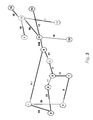
FIG. 3 is a schematic of example edge demands in the network of FIG. 2;
FIG. 4 is a flow diagram of a method to reoptimize energy efficiency of the network according to embodiments of the invention;
FIG. 5 is a schematic of the network graph after the first step of the method;
FIG. 6 is a schematic of the network graph after the second step of the method;
FIG. 7 is a schematic of the network graph after the third step of the method;
FIG. 8 is a schematic of the network graph after the method is complete;
DETAILED DESCRIPTION OF THE PREFERRED EMBODIMENT
In general, the energy consumption of the network is dominated by the switching and routing functions. An ODU Cross-Connect (XC) has reduced energy consumption per bit compared to a Layer 3 (L3) router, Ethernet Switch or SONET/SDH XC. In addition, larger ODU sizes require less energy to switch and transport than smaller ODU sizes. The ODU sizes are not continuously adjustable; rather the currently defined sizes are 1.25 Gbps (ODU0), 2.5 Gbps (ODU1), 10 Gbps (ODU2), 40 Gbps (ODU3), and 100 Gbps (ODU4). However, for illustration of the methods we assume that the energy consumption ES as a function of data rate R is a continuous concave function with diminishing slope, as shown in FIG. 1. Specifically for the values presented we assume that ES(R)=2*sqrt(R). Note that every link has a maximum capacity.
Because ES is a concave function with diminishing slope, the marginal energy consumption, E′S (where the symbol ES′ denotes the derivative of ES), will be a continuously reducing function. Thus, for the values presented we assume that E′S(R)=1/sqrt(R).
We now consider the example network shown in FIG. 2 including fifteen nodes, labeled 1, 2, . . . 15, and optical links, which are denoted by the lines connecting the nodes. The nodes represent optical network element, e.g., routers, switches, and cross-connects. In general, the energy consumption of the network is dominated by the switching and routing functions. An ODU Cross-Connect (XC) has reduced energy consumption per bit compared to a Layer 3 (L3) router, Ethernet Switch or SONET/SDH XC. In addition, larger ODU sizes require less energy to switch and transport than smaller ODU sizes. The optical link between two adjacent nodes is termed an “edge.” We define a “path” as a sequence of connected edges linking two nodes. The traffic demand between a source node and a given destination node j is termed the “demand,” denoted by D(i, j).
To illustrate the energy reduction method, we assume the network in FIG. 2 with a single source node i=1 with fourteen destination nodes j, 2, . . . 15. The demand D(1, j), is given by the values next to the nodes. For example, the demand D(1, 3) is equal to 22 units of traffic, D(1, 3) is equal to 12 units of traffic and D(1, 4) is equal to 8 units of traffic.
In the general case there may be more than one path linking two nodes and so the demand is be shared across each path. If there are M paths defined between nodes i and j, the traffic demand for path k (where k=1, . . . , M) is termed the “path demand” and is denoted by PD(i,j,k). Note that the demand is equal to the sum of the path demands, that is D(i,j)=Σ1 MPD(i,j,k). As there are many source and destination nodes, a given edge has traffic associated with a number of different paths. The traffic demand on an edge is termed the “edge demand.”
As described by way of example below, the edge demand on any particular link, (i,j), is a function of the total demand between all sources and destinations and the number of paths between sources that contain the edge (i,j). The capacity of each edge to carry any portion of the demand can initially be allocate so that the basic constraints are satisfied, i.e., all demands are satisfied and no edge is allocated more demand than its capacity. Thus, the demand can be allocated in a number of ways. We assume edge demands as shown in FIG. 3, and we describe, how given a new allocation that lowers the energy consumption can be found for the initial edge demand allocation.
For most nodes, there are multiple possible paths through the network to get from node j to node 1 to satisfy the demand. For example, from node 11 there is one possible path to node 1 using nodes using nodes 11
Figure US08891967-20141118-P00001
8
Figure US08891967-20141118-P00001
6
Figure US08891967-20141118-P00001
5
Figure US08891967-20141118-P00001
4
Figure US08891967-20141118-P00001
2
Figure US08891967-20141118-P00001
1 (amongst other options), where “
Figure US08891967-20141118-P00001
” indicates an edge. Note that edges can be unidirectional, bidirectional with different edge demands in each direction, or bidirectional with equal edge demands in each direction. Bidirectional edges with equal edge demands are shown for simplicity.
In FIG. 3, for the purposes of illustration we assume that the demand from node 1 to node N, (N=2, 3, . . . , 15) is supported by only one path, except for 1
Figure US08891967-20141118-P00001
7 and 1
Figure US08891967-20141118-P00001
5, whose demand is split amongst 3 paths each. The demands are split over the following paths: 1
Figure US08891967-20141118-P00001
7 demand, split into paths 1
Figure US08891967-20141118-P00001
3
Figure US08891967-20141118-P00001
7, 1
Figure US08891967-20141118-P00001
2
Figure US08891967-20141118-P00001
4
Figure US08891967-20141118-P00001
5
Figure US08891967-20141118-P00001
7 and 1
Figure US08891967-20141118-P00001
8
Figure US08891967-20141118-P00001
6
Figure US08891967-20141118-P00001
5
Figure US08891967-20141118-P00001
7 with path demands 1, 2 and 2 respectively (total of 5, which is the 1
Figure US08891967-20141118-P00001
7 demand), and 1
Figure US08891967-20141118-P00001
5 demand, split into paths 1
Figure US08891967-20141118-P00001
3
Figure US08891967-20141118-P00001
7
Figure US08891967-20141118-P00001
5, 1
Figure US08891967-20141118-P00001
2
Figure US08891967-20141118-P00001
4
Figure US08891967-20141118-P00001
5
Figure US08891967-20141118-P00001
and 1
Figure US08891967-20141118-P00001
8
Figure US08891967-20141118-P00001
6
Figure US08891967-20141118-P00001
5 with paths demands 7, 12 and 4 respectively (total of 23, which is the 1
Figure US08891967-20141118-P00001
5 demand). The total energy consumed by the network using the assumptions provided earlier is the sum of all the edge energies given by 2√{square root over (edge demand)}. In this case, the total energy consumed is 163.2 units of energy.
FIG. 4 shows a method for improving energy efficiency in an optical network while satisfying all the demands at each step according to the embodiments of the invention. The steps of the method, and any other processes described herein can be performed in a processor connected to memory and input/output interfaces as known in the art.
First, we construct 410 a graph representing network. The network include node connected by edges. The edges are associated traffic demands between the nodes.
We identify and exclude 420 bridge edges in the network using the graph, where a “bridge edge” is an edge, if removed, results in an unconnected network. This can be performed using a known procedure.
Next, we identify and remove 430 which of the remaining edges has a highest marginal energy (lowest demand). This edge is removed from the network and the lowest demand is added 330 to the edge with the lowest marginal energy that meets the following conditions: supports the required demand, and does not exceed the capacity of any given edge in the altered network
If two or more edges have the same lowest marginal energy, then one is selected arbitrarily.
We now check 450 to see if all remaining edges in the network are bridge edges and if yes, terminate 455. If no, check 460 if a maximum number of allowed iterations has been exceeded and if yes, terminate 465. If not, then repeat beginning at step 420.
FIG. 5 shows the network graph at steps 420 and 430. The bridge edges determined in step 420 are illustrated by the dashed lines. The edge identified to have the highest marginal energy (lowest demand) in step 430 is edge 5
Figure US08891967-20141118-P00001
6 510.
FIG. 6 shows the network graph at steps 430 and 440. The 5
Figure US08891967-20141118-P00001
6 edge is removed from the network and the removed edge demand (6) is added to the edges 5
Figure US08891967-20141118-P00001
4, 4
Figure US08891967-20141118-P00001
2, 2
Figure US08891967-20141118-P00001
1 because the lowest marginal energy edge supporting paths which use node 5 is the 5
Figure US08891967-20141118-P00001
4 edge. It is also removed from the 6
Figure US08891967-20141118-P00001
8 and 8
Figure US08891967-20141118-P00001
1 edges because it is no longer needed to support paths using those nodes. Because not all edges are bridge edges the method will continue. In the next iteration the edge 610 to be removed is 3
Figure US08891967-20141118-P00001
7.
FIG. 7 shows the network graph after step 420 and 430 of the second iteration. The edges 710 and 720 have been identified as bridge edges and removed from consideration. The 3
Figure US08891967-20141118-P00001
7 edge has also been removed and its demand added to the other edges as described previously. At this stage all the edges are bridge edges and so the method terminates.
FIG. 8 shows the network graph after the method has completed. The total energy is computed as before for the new network and found to be 154.2, a saving of (163.2−154.2)/163.2=5.5% in this example.
For multiple-source multiple-destination, the algorithm is analogous to the single-source case. The edge demand is found as before, but considering all demands between the N nodes, D(1, j) rather than just the demands from a root node, D(1, j) in the example presented. The bridge edges are removed and the edge with the highest marginal energy that supports the two conditions described is found. This edge is then removed and its edge demand is redistributed over the other edges for each of the paths that are supported by this edge. This procedure continues as before until the maximum number of iterations is reached, or there are no more bridge edges.
Extension to Other Protocols
The prior descriptions dealt only with OTN, but it is important to note that the same algorithms can be applied to other protocols, including those transported by OTN. As an example, consider Label Switched Paths (LSPs) in MPLS (Multi-Label Protocol Switching). LSPs can be carried by OTN and may be quasi-static in nature. As such, they may be reoptimized so that they are carried by higher rate ODUs so freeing up lower rate ODUs and improving energy efficiency. This uses the same algorithm as described.
Although the invention has been described by way of examples of preferred embodiments, it is to be understood that various other adaptations and modifications may be made within the spirit and scope of the invention. Therefore, it is the object of the appended claims to cover all such variations and modifications as come within the true spirit and scope of the invention.

Claims (6)

We claim:
1. A method for improving an efficiency of transferring energy in an optical network including a plurality of source nodes, and a plurality of destination nodes, comprising the steps of:
representing the network as a graph of nodes connected by edges, wherein each node represents an optical network element and each edge represents an optical link connecting two adjacent optical network elements;
labeling each edge with an edge demand, wherein the edge demand is a demand for units of traffic in the optical network through the edge, the edge demand equals a sum of path demands for a number of paths in the graph through the edge according to D(i,j)=Σ1 MPD(i,j,k), wherein D(i,j) is the edge demand of the edge between nodes i and j, M is the number of paths between the nodes i and j, PD(i,j,k) is a path demand of a path k, k=1, . . . M;
identifying non-bridge edges;
removing the non-bridge edge with a lowest edge demand from the graph, wherein the lowest edge demand is greater than zero;
adding the lowest edge demand to the non-bridge edge with a highest edge demand, wherein the lowest edge demand corresponds to a highest marginal energy, and a highest edge demand corresponds to a lowest marginal energy;
repeating the labeling, identifying, removing and adding steps until a termination condition is reached; and
commanding to redistribute the units of traffic according a topology of the graph upon reaching the termination condition, wherein steps of the method are performed by a processor.
2. The method of claim 1, wherein the marginal energy is a derivative of an energy consumption.
3. The method of claim 1, wherein the lowest demand is only added if a capacity of the non-bridge edge is not exceeded.
4. The method of claim 1, wherein multiple edges have a highest demand, and the lowest demand is arbitrarily added to one of the multiple edges.
5. The method of claim 1, wherein the termination condition is that all edges are bridge edges.
6. The method of claim 1, wherein the termination condition is a maximum number of iterations.
US13/218,044 2011-08-25 2011-08-25 Method for energy efficient reoptimization of optical networks Expired - Fee Related US8891967B2 (en)

Priority Applications (2)

Application Number Priority Date Filing Date Title
US13/218,044 US8891967B2 (en) 2011-08-25 2011-08-25 Method for energy efficient reoptimization of optical networks
JP2012151551A JP5904892B2 (en) 2011-08-25 2012-07-05 A method for energy efficient reoptimization of optical networks

Applications Claiming Priority (1)

Application Number Priority Date Filing Date Title
US13/218,044 US8891967B2 (en) 2011-08-25 2011-08-25 Method for energy efficient reoptimization of optical networks

Publications (2)

Publication Number Publication Date
US20130051797A1 US20130051797A1 (en) 2013-02-28
US8891967B2 true US8891967B2 (en) 2014-11-18

Family

ID=47743889

Family Applications (1)

Application Number Title Priority Date Filing Date
US13/218,044 Expired - Fee Related US8891967B2 (en) 2011-08-25 2011-08-25 Method for energy efficient reoptimization of optical networks

Country Status (2)

Country Link
US (1) US8891967B2 (en)
JP (1) JP5904892B2 (en)

Cited By (1)

* Cited by examiner, † Cited by third party
Publication number Priority date Publication date Assignee Title
US20160057519A1 (en) * 2014-08-25 2016-02-25 Infinera Corporation Assignment of wavelengths to optical signals in an optical network

Families Citing this family (1)

* Cited by examiner, † Cited by third party
Publication number Priority date Publication date Assignee Title
JP6697107B2 (en) * 2019-04-18 2020-05-20 株式会社荏原製作所 Scheduler, substrate processing apparatus, and substrate transfer method

Citations (28)

* Cited by examiner, † Cited by third party
Publication number Priority date Publication date Assignee Title
US720956A (en) * 1902-05-01 1903-02-17 Julius Dietrich Upholstery-spring.
US20020105915A1 (en) * 2001-02-06 2002-08-08 Tsuneo Hamada Method of and apparatus for calculating traffic from data on packet transmission collected from routers
US20030161633A1 (en) * 2002-02-28 2003-08-28 Eiji Oki Node used in photonic network, and photonic network
US20040077354A1 (en) * 2002-10-21 2004-04-22 Hong Kong Applied Science And Technology Research Institute Co. Ltd. Systems and methods for managing wireless communications using link space information
US20040115703A1 (en) * 2002-09-06 2004-06-17 Vanderbilt University Rapid assays for neurotransmitter transporters
US20040208513A1 (en) * 2002-04-12 2004-10-21 Fujitsu Network Communications, Inc. Management of optical links using power level information
US20040208511A1 (en) * 2002-04-12 2004-10-21 Fujitsu Network Communications, Inc. Power level management in optical networks
US20040208512A1 (en) * 2002-04-12 2004-10-21 Fujitsu Network Communications, Inc. Sharing of power level information to support optical communications
US20040208556A1 (en) * 2002-01-14 2004-10-21 Robert Joly Optical network with high density, signaled sources at the edge of the network
US7020394B2 (en) * 2001-08-17 2006-03-28 Quantum Bridge Communications, Inc. Method and apparatus for path selection and wavelength assignment in an optical network
US7095956B2 (en) * 2000-06-08 2006-08-22 Tellabs Operations, Inc. Method and apparatus for validating a path through a switched optical network
US20060188252A1 (en) * 2003-07-24 2006-08-24 Paul Schluter Method for determiming a link path and a corresponding unoccupied wavelength channel
US7224897B1 (en) * 2003-04-28 2007-05-29 Lucent Technologies Inc. Method of preconfiguring optical protection trails in a mesh-connected agile photonic network
US7251703B1 (en) * 2004-02-27 2007-07-31 Entropic Communications, Inc. Method of time stamping to enable device bridging over dissimilar buses
US20090010647A1 (en) * 2007-07-06 2009-01-08 Jenkins David W Method and apparatus for routing communications in a mesh network
US20090296719A1 (en) * 2005-08-08 2009-12-03 Guido Alberto Maier Method for Configuring an Optical Network
US20100266281A1 (en) * 2009-04-15 2010-10-21 Fujitsu Limited Allocating Demand According To Demand Weight
US20100329276A1 (en) * 2009-06-30 2010-12-30 Ren Wang Energy efficient network forwarding
US20110188865A1 (en) * 2010-02-04 2011-08-04 Nortel Networks Limited Method for rapid determination of lowest cost wavelength routes through a photonic network based on pre-validated paths
US20110228705A1 (en) * 2008-05-13 2011-09-22 Nortel Networks Limited Wireless mesh network transit link topology optimization method and system
US20110286336A1 (en) * 2006-11-28 2011-11-24 Cisco Technology, Inc. Relaxed constrained shortest path first (r-cspf)
US20120170934A1 (en) * 2011-01-05 2012-07-05 Raymond Yim Methods for Determining Energy Efficient Optical Routes
US20120198092A1 (en) * 2011-02-01 2012-08-02 Cisco Technology, Inc. Network Topologies for Energy Efficient Networks
US8238748B2 (en) * 2008-12-24 2012-08-07 Infinera Corporation Method for wavelength assignment in a WDM network
US20120207048A1 (en) * 2011-02-16 2012-08-16 Samsung Electronics Co. Ltd. Method and apparatus for down link interference cancelation between adjacent base stations in base station with reconfigurable antenna
US20120323833A1 (en) * 2010-02-05 2012-12-20 Ecole Polytechnique Federale De Lausanne (Epfl) Organizing Neural Networks
US20130177312A1 (en) * 2012-01-11 2013-07-11 Thyaga Nandagopal Method and system for energy efficient routing of ip packets over optical backbone networks
US20140016925A1 (en) * 2011-02-16 2014-01-16 Telefonaktiebolaget I.M Ericsson (publ) Resizing a path in a connection-oriented network

Family Cites Families (1)

* Cited by examiner, † Cited by third party
Publication number Priority date Publication date Assignee Title
JP5113093B2 (en) * 2009-01-06 2013-01-09 Kddi株式会社 Network management system and management method

Patent Citations (33)

* Cited by examiner, † Cited by third party
Publication number Priority date Publication date Assignee Title
US720956A (en) * 1902-05-01 1903-02-17 Julius Dietrich Upholstery-spring.
US7095956B2 (en) * 2000-06-08 2006-08-22 Tellabs Operations, Inc. Method and apparatus for validating a path through a switched optical network
US20020105915A1 (en) * 2001-02-06 2002-08-08 Tsuneo Hamada Method of and apparatus for calculating traffic from data on packet transmission collected from routers
US7020394B2 (en) * 2001-08-17 2006-03-28 Quantum Bridge Communications, Inc. Method and apparatus for path selection and wavelength assignment in an optical network
US20040208556A1 (en) * 2002-01-14 2004-10-21 Robert Joly Optical network with high density, signaled sources at the edge of the network
US20030161633A1 (en) * 2002-02-28 2003-08-28 Eiji Oki Node used in photonic network, and photonic network
US20040208513A1 (en) * 2002-04-12 2004-10-21 Fujitsu Network Communications, Inc. Management of optical links using power level information
US7212742B2 (en) * 2002-04-12 2007-05-01 Fujitsu Limited Power level management in optical networks
US20040208511A1 (en) * 2002-04-12 2004-10-21 Fujitsu Network Communications, Inc. Power level management in optical networks
US7609964B2 (en) * 2002-04-12 2009-10-27 Fujitsu Limited Power level management in optical networks
US20040208512A1 (en) * 2002-04-12 2004-10-21 Fujitsu Network Communications, Inc. Sharing of power level information to support optical communications
US20040115703A1 (en) * 2002-09-06 2004-06-17 Vanderbilt University Rapid assays for neurotransmitter transporters
US20040077354A1 (en) * 2002-10-21 2004-04-22 Hong Kong Applied Science And Technology Research Institute Co. Ltd. Systems and methods for managing wireless communications using link space information
US20080214116A1 (en) * 2002-10-21 2008-09-04 Hong Kong Applied Science And Technology Research Institute Co., Ltd. Systems and Methods for Managing Wireless Communications Using Link Space Information
US8280388B2 (en) * 2002-10-21 2012-10-02 Hong Kong Applied Science And Technology Research Institute Co., Ltd. Systems and methods for managing wireless communications using link space information
US7224897B1 (en) * 2003-04-28 2007-05-29 Lucent Technologies Inc. Method of preconfiguring optical protection trails in a mesh-connected agile photonic network
US20060188252A1 (en) * 2003-07-24 2006-08-24 Paul Schluter Method for determiming a link path and a corresponding unoccupied wavelength channel
US7251703B1 (en) * 2004-02-27 2007-07-31 Entropic Communications, Inc. Method of time stamping to enable device bridging over dissimilar buses
US20090296719A1 (en) * 2005-08-08 2009-12-03 Guido Alberto Maier Method for Configuring an Optical Network
US20110286336A1 (en) * 2006-11-28 2011-11-24 Cisco Technology, Inc. Relaxed constrained shortest path first (r-cspf)
US20090010647A1 (en) * 2007-07-06 2009-01-08 Jenkins David W Method and apparatus for routing communications in a mesh network
US20110228705A1 (en) * 2008-05-13 2011-09-22 Nortel Networks Limited Wireless mesh network transit link topology optimization method and system
US8238748B2 (en) * 2008-12-24 2012-08-07 Infinera Corporation Method for wavelength assignment in a WDM network
US20100266281A1 (en) * 2009-04-15 2010-10-21 Fujitsu Limited Allocating Demand According To Demand Weight
US20100329276A1 (en) * 2009-06-30 2010-12-30 Ren Wang Energy efficient network forwarding
US20110188865A1 (en) * 2010-02-04 2011-08-04 Nortel Networks Limited Method for rapid determination of lowest cost wavelength routes through a photonic network based on pre-validated paths
US20120323833A1 (en) * 2010-02-05 2012-12-20 Ecole Polytechnique Federale De Lausanne (Epfl) Organizing Neural Networks
US20120170934A1 (en) * 2011-01-05 2012-07-05 Raymond Yim Methods for Determining Energy Efficient Optical Routes
US8634714B2 (en) * 2011-01-05 2014-01-21 Mitsubishi Electric Research Laboratories, Inc. Methods for determining energy efficient optical routes
US20120198092A1 (en) * 2011-02-01 2012-08-02 Cisco Technology, Inc. Network Topologies for Energy Efficient Networks
US20120207048A1 (en) * 2011-02-16 2012-08-16 Samsung Electronics Co. Ltd. Method and apparatus for down link interference cancelation between adjacent base stations in base station with reconfigurable antenna
US20140016925A1 (en) * 2011-02-16 2014-01-16 Telefonaktiebolaget I.M Ericsson (publ) Resizing a path in a connection-oriented network
US20130177312A1 (en) * 2012-01-11 2013-07-11 Thyaga Nandagopal Method and system for energy efficient routing of ip packets over optical backbone networks

Non-Patent Citations (3)

* Cited by examiner, † Cited by third party
Title
Baliga et al;Energy consumption in optical IP networks; Jul. 1 2009; Journal of Lightwave Technology, vol. 27 No. 13; pp. 2391-2403. *
Fang Zhou et al; Network simpliifcation with Minimal loss connectivity; 2010; IEEE international conference on Data mining; pp. 659-668. *
Zhou et al; network simpliifcation with minimal loss of connectivity; 2010; IEEE International conference on Data mining ;pp. 659-668. *

Cited By (2)

* Cited by examiner, † Cited by third party
Publication number Priority date Publication date Assignee Title
US20160057519A1 (en) * 2014-08-25 2016-02-25 Infinera Corporation Assignment of wavelengths to optical signals in an optical network
US9445166B2 (en) * 2014-08-25 2016-09-13 Infinera Corporation Assignment of wavelengths to optical signals in an optical network

Also Published As

Publication number Publication date
JP2013046414A (en) 2013-03-04
US20130051797A1 (en) 2013-02-28
JP5904892B2 (en) 2016-04-20

Similar Documents

Publication Publication Date Title
US10148578B2 (en) Optical and packet path computation and selection systems and methods
EP3036869B1 (en) Reconfigurable and variable-rate shared multi-transponder architecture for flexible ethernet-based optical networks
CN1708032B (en) Efficient and robust routing independent of traffic pattern variability
US7813270B2 (en) Route precomputation method and apparatus for bandwidth guaranteed traffic
CN101312464B (en) Method for realizing load balance in automatic exchange optical network
US20160119076A1 (en) Channelized oduflex systems and methods
CN104956630B (en) Enhanced routing scheme for the equative route in communication network
CN102136865B (en) Service recovering method, system and node device
EP1641198B1 (en) Method for routing traffic using traffic weighting factors
CN101127689A (en) Method for minimizing priority seizing cost
US8891967B2 (en) Method for energy efficient reoptimization of optical networks
CN102195818B (en) Data service processing single board and method
CN108184175B (en) MC node limitation-based elastic optical network multicast routing and spectrum allocation method
US20220038391A1 (en) Programmatically configured switches and distributed buffering across fabric interconnect
JP5734175B2 (en) How to create a bypass in an optical network
CN102014313A (en) Method and device for realizing link information publishing by nodes
CN106911393B (en) What shared optical path merged appoints multicast service to route minimal frequency light tree generation method
US7675899B2 (en) Packet-aware transport architecture for enhanced data volume
CN114745227A (en) Power service network slice time delay calculation method and device based on Flexe and SPN technologies
CN101159668B (en) Pseudo-lines and packet switching conveyor network based establishment method
US20120117269A1 (en) Systems and methods for multi-layer traffic grooming
CN111245720A (en) Path calculation method and system
CN102130827B (en) Path calculation method and node equipment
Kadohata Adaptive reconfiguration of sub-lambda and wavelength paths for unpredictable traffic demands
CN106254249B (en) A kind of method for routing of optical transfer network OTN

Legal Events

Date Code Title Description
AS Assignment

Owner name: MITSUBISHI ELECTRIC RESEARCH LABORATORIES, INC., M

Free format text: ASSIGNMENT OF ASSIGNORS INTEREST;ASSIGNORS:PARSONS, KIERAN;ORLIK, PHILIP;REEL/FRAME:027705/0103

Effective date: 20120213

STCF Information on status: patent grant

Free format text: PATENTED CASE

MAFP Maintenance fee payment

Free format text: PAYMENT OF MAINTENANCE FEE, 4TH YEAR, LARGE ENTITY (ORIGINAL EVENT CODE: M1551)

Year of fee payment: 4

FEPP Fee payment procedure

Free format text: MAINTENANCE FEE REMINDER MAILED (ORIGINAL EVENT CODE: REM.); ENTITY STATUS OF PATENT OWNER: LARGE ENTITY

LAPS Lapse for failure to pay maintenance fees

Free format text: PATENT EXPIRED FOR FAILURE TO PAY MAINTENANCE FEES (ORIGINAL EVENT CODE: EXP.); ENTITY STATUS OF PATENT OWNER: LARGE ENTITY

STCH Information on status: patent discontinuation

Free format text: PATENT EXPIRED DUE TO NONPAYMENT OF MAINTENANCE FEES UNDER 37 CFR 1.362

FP Lapsed due to failure to pay maintenance fee

Effective date: 20221118