US8899121B2 - Spindle drive - Google Patents
Spindle drive Download PDFInfo
- Publication number
- US8899121B2 US8899121B2 US13/328,191 US201113328191A US8899121B2 US 8899121 B2 US8899121 B2 US 8899121B2 US 201113328191 A US201113328191 A US 201113328191A US 8899121 B2 US8899121 B2 US 8899121B2
- Authority
- US
- United States
- Prior art keywords
- carriage
- guide
- switching
- spindle
- guide carriages
- Prior art date
- Legal status (The legal status is an assumption and is not a legal conclusion. Google has not performed a legal analysis and makes no representation as to the accuracy of the status listed.)
- Expired - Fee Related, expires
Links
Images


Classifications
-
- F—MECHANICAL ENGINEERING; LIGHTING; HEATING; WEAPONS; BLASTING
- F16—ENGINEERING ELEMENTS AND UNITS; GENERAL MEASURES FOR PRODUCING AND MAINTAINING EFFECTIVE FUNCTIONING OF MACHINES OR INSTALLATIONS; THERMAL INSULATION IN GENERAL
- F16H—GEARING
- F16H25/00—Gearings comprising primarily only cams, cam-followers and screw-and-nut mechanisms
- F16H25/18—Gearings comprising primarily only cams, cam-followers and screw-and-nut mechanisms for conveying or interconverting oscillating or reciprocating motions
- F16H25/20—Screw mechanisms
- F16H25/24—Elements essential to such mechanisms, e.g. screws, nuts
-
- B—PERFORMING OPERATIONS; TRANSPORTING
- B23—MACHINE TOOLS; METAL-WORKING NOT OTHERWISE PROVIDED FOR
- B23Q—DETAILS, COMPONENTS, OR ACCESSORIES FOR MACHINE TOOLS, e.g. ARRANGEMENTS FOR COPYING OR CONTROLLING; MACHINE TOOLS IN GENERAL CHARACTERISED BY THE CONSTRUCTION OF PARTICULAR DETAILS OR COMPONENTS; COMBINATIONS OR ASSOCIATIONS OF METAL-WORKING MACHINES, NOT DIRECTED TO A PARTICULAR RESULT
- B23Q5/00—Driving or feeding mechanisms; Control arrangements therefor
- B23Q5/22—Feeding members carrying tools or work
- B23Q5/34—Feeding other members supporting tools or work, e.g. saddles, tool-slides, through mechanical transmission
- B23Q5/38—Feeding other members supporting tools or work, e.g. saddles, tool-slides, through mechanical transmission feeding continuously
- B23Q5/40—Feeding other members supporting tools or work, e.g. saddles, tool-slides, through mechanical transmission feeding continuously by feed shaft, e.g. lead screw
- B23Q5/404—Screw bearings therefor
-
- F—MECHANICAL ENGINEERING; LIGHTING; HEATING; WEAPONS; BLASTING
- F16—ENGINEERING ELEMENTS AND UNITS; GENERAL MEASURES FOR PRODUCING AND MAINTAINING EFFECTIVE FUNCTIONING OF MACHINES OR INSTALLATIONS; THERMAL INSULATION IN GENERAL
- F16H—GEARING
- F16H25/00—Gearings comprising primarily only cams, cam-followers and screw-and-nut mechanisms
- F16H25/18—Gearings comprising primarily only cams, cam-followers and screw-and-nut mechanisms for conveying or interconverting oscillating or reciprocating motions
- F16H25/20—Screw mechanisms
- F16H25/24—Elements essential to such mechanisms, e.g. screws, nuts
- F16H2025/2436—Intermediate screw supports for reducing unsupported length of screw shaft
-
- Y—GENERAL TAGGING OF NEW TECHNOLOGICAL DEVELOPMENTS; GENERAL TAGGING OF CROSS-SECTIONAL TECHNOLOGIES SPANNING OVER SEVERAL SECTIONS OF THE IPC; TECHNICAL SUBJECTS COVERED BY FORMER USPC CROSS-REFERENCE ART COLLECTIONS [XRACs] AND DIGESTS
- Y10—TECHNICAL SUBJECTS COVERED BY FORMER USPC
- Y10T—TECHNICAL SUBJECTS COVERED BY FORMER US CLASSIFICATION
- Y10T74/00—Machine element or mechanism
- Y10T74/18—Mechanical movements
- Y10T74/18568—Reciprocating or oscillating to or from alternating rotary
- Y10T74/18576—Reciprocating or oscillating to or from alternating rotary including screw and nut
- Y10T74/18624—Plural inputs, single output
- Y10T74/1864—Shaft and nut driven
-
- Y—GENERAL TAGGING OF NEW TECHNOLOGICAL DEVELOPMENTS; GENERAL TAGGING OF CROSS-SECTIONAL TECHNOLOGIES SPANNING OVER SEVERAL SECTIONS OF THE IPC; TECHNICAL SUBJECTS COVERED BY FORMER USPC CROSS-REFERENCE ART COLLECTIONS [XRACs] AND DIGESTS
- Y10—TECHNICAL SUBJECTS COVERED BY FORMER USPC
- Y10T—TECHNICAL SUBJECTS COVERED BY FORMER US CLASSIFICATION
- Y10T74/00—Machine element or mechanism
- Y10T74/18—Mechanical movements
- Y10T74/18568—Reciprocating or oscillating to or from alternating rotary
- Y10T74/18576—Reciprocating or oscillating to or from alternating rotary including screw and nut
- Y10T74/1868—Deflection related
-
- Y—GENERAL TAGGING OF NEW TECHNOLOGICAL DEVELOPMENTS; GENERAL TAGGING OF CROSS-SECTIONAL TECHNOLOGIES SPANNING OVER SEVERAL SECTIONS OF THE IPC; TECHNICAL SUBJECTS COVERED BY FORMER USPC CROSS-REFERENCE ART COLLECTIONS [XRACs] AND DIGESTS
- Y10—TECHNICAL SUBJECTS COVERED BY FORMER USPC
- Y10T—TECHNICAL SUBJECTS COVERED BY FORMER US CLASSIFICATION
- Y10T74/00—Machine element or mechanism
- Y10T74/18—Mechanical movements
- Y10T74/18568—Reciprocating or oscillating to or from alternating rotary
- Y10T74/18576—Reciprocating or oscillating to or from alternating rotary including screw and nut
- Y10T74/18704—Means to selectively lock or retard screw or nut
Definitions
- the invention relates to a spindle drive comprising a threaded spindle that can be driven rotationally, a carriage displaceable along a guide rail via said threaded spindle, as well as several guide carriages arranged in front and behind the carriage in the direction of the spindle axis for supporting the threaded spindle, with in an advancing motion of the carriage the guide carriages arranged in front thereof being successively pushed together by the carriage and moved towards one end of the spindle, and with the guide carriages arranged behind the carriage being dragged via a coupling mechanism and being moved into an allocated support position.
- spindle drives are frequently used for a motorized drive of linearly movable parts, for example machine tables, coordinate measurement devices, and the like.
- a spindle nut is arranged with an internal thread matching the external thread of the threaded spindle, which during the rotation of the threaded spindle, is moved along the spindle axis and entrains the part to be moved.
- the maximum drive speed of the carriage depends on the critical rotation speed of the threaded spindle.
- the threaded spindle Upon reaching the critical rotation the threaded spindle is set into natural oscillation, which aggravates a precise positioning of the carriage or renders it even impossible.
- Relevant factors determining a critical rotation speed are the diameter of the threaded spindle and particularly its length. The smaller the ratio of the diameter in reference to the length of the threaded spindle the lower the critical rotation speed of the threaded spindle and thus the feed rate that can be achieved.
- a spindle drive is known in which the guide carriages, here called spindle support units, are connected to each other in pairs or via a pulley-like connection to the carriage.
- the guide carriages here called spindle support units
- spindle support units are connected to each other in pairs or via a pulley-like connection to the carriage.
- such solutions are of extremely complicated construction and extensive in their technical assembly because numerous pulley cables must be installed and connected to the guide carriage and/or the carriage. This particularly applies if more than two guide carriages are arranged in front and/or behind the carriage so that such a design with more than two guide carriages can hardly be implemented according to this principle.
- the invention is based on the objective of providing a spindle drive of the type mentioned above, which is of simple design as well as reliable, and which also allows to arrange more than two guide carriages in front and/or behind the carriage on the threaded spindle.
- the invention is based on the acknowledgement that particularly the placement of the guide carriages entrained to their predetermined support positions can be simplified when it is possible to implement this placement by switching means arranged at said placement positions.
- the invention is based on a spindle drive, comprising a threaded spindle that can be rotationally driven, a carriage adjustable via the threaded spindle along a guide rail, as well as several guide carriages arranged in the direction of the spindle axis in front and behind the carriage to support the threaded spindle, with the guide carriages arranged in front of the carriage during the driving and/or advancing motion being successively pushed together by the carriage and moved towards a spindle end, and with the guide carriages arranged behind the carriage being dragged by a coupling mechanism and moved into an allocated support position.
- coupling means are provided, cooperating with each other on the guide carriages and on the carriage, which can be operated by switching means arranged fixed on the guide rail, by which the guide carriages arranged in front of the carriage can be automatically coupled to the guide carriages respectively approaching from the rear in the subsequent displacement motion, and by which the dragged guide carriages upon reaching their support position are successively and automatically decoupled and placed.
- the carriage When the carriage is moved in a feed direction for example from a central position, in which the guide carriages are each equally distributed over the threaded spindle sections in front and/or behind the carriage, respectively, it approaches the closest positioned first guide carriage in the feed direction, with the coupling means arranged on the carriage on the one side and on the guide carriage on the other side reach a coupling position.
- the group comprising the carriage and guide carriage pass the switching means allocated to the guide carriage, which brings the coupling means into a coupling engagement.
- a first coupling element is provided on each guide carriage, cooperating with a second coupling element arranged on the guide carriage and/or the carriage accumulating during the feed motion.
- one of the coupling elements of a pair of coupling elements can be switched between a locked position and an unlocked position.
- a switching ramp or the like is arranged each, which switches the switchable coupling element of the guide carriage allocated to this support position when being displaced out of the support position into a locking state and when being displaced into the support position into its unlocked state.
- the second coupling element can be arranged fixed on a guide carriage and the carriage, respectively, embodied as a locking pin extending in the accumulating direction, which penetrates into a receiving bore of a guide carriage to be coupled.
- the first coupling element is embodied as a latch, adjustable perpendicularly in reference to the axis of the locking pin and engaging a latching groove embodied on the locking pin, which via a switching cam arranged thereat and cooperating with the switching ramp is moved in the unlocking direction against the force of springs.
- the springs therefore serve to pre-stress the latch in the direction of the locking position.
- the switching ramp is embodied as a separate switching bar, that can be inserted into an allocated recess on the inside of a lateral wall of the guide rail, which is U-shaped in its cross-section. The position of the switching bar therefore determines the support position of an allocated guide carriage.
- a latching recess is provided on the switching bar, engaged by the latch allocated to the switching cam in order to fix the guide carriage in its support position.
- the guide carriage comprises a housing with a penetrating opening for the threaded spindle and a slide bush arranged in the penetrating opening and receiving and supporting the threaded spindle, with at least one receiving bore being arranged in the housing each for receiving the locking pin, at least one recess for receiving and guiding a latch, and a locking pin projecting in the feed direction, as explained in greater detail using the exemplary embodiment below.
- the housing is embodied with respect to a plane perpendicular in reference to the bottom wall of the guide rail and comprising the axis of the threaded bore symmetrical, with recess bores arranged on both sides of the plane for a locking pin and one recess each for a latch.
- this constructive design allows that in front and behind the carriage one group each of four guide carriages can be provided.
- the latches of the four guide carriages of a group are embodied and arranged such that one switching cam each of a guide carriage for example is arranged at the right side with regards to the accumulating direction and in a lower section of the housing, the switching cam of another guide carriage on the right side in the upper section of the housing, the switching cam of another guide carriage on the left side in the lower section, and the switching cam of another guide carriage on the left side in the upper section of the housing, with four switching bars accordingly being arranged at the interior side of the right and/or left lateral wall of the guide rail being arranged at a height according to the position of the switching cams.
- FIG. 1 is a perspective, partially cross-sectional view of an end section of a guide rail with a carriage and two guide carriages, not coupled to the carriage and arranged in front of it in the feed direction, namely in a view from the front left with regards to the feed direction,
- FIG. 2 is a view of the carriage and the guide carriages according to FIG. 1 in a state coupled to each other,
- FIG. 3 is an enlarged view of the carriage and the guide carriages adjacent thereto according to FIG. 2 ,
- FIG. 4 is a view of the arrangement according to FIG. 2 taken from the front right with regards to the feed direction,
- FIG. 5 is a view of the guide carriage adjacent to the carriage according to FIG. 4 from the right rear in an enlarged illustration with a latch acting left with regards to the feed direction,
- FIG. 6 is a view of the guide carriage according to FIG. 5 , with an allocated switching bar
- FIGS. 7 and 8 are views of the guide carriage spaced apart from the carriage according to FIG. 4 in illustrations similar to FIGS. 5 and 6 ,
- FIG. 9 is an exploded view of the guide carriage according to FIGS. 7 and 8 .
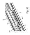
- FIG. 10 is a view, partially cross-sectioned illustration, of a guide rail with switching bars arranged therein.
- the spindle drive shown in FIG. 1 comprises a threaded spindle 2 that can be rotationally driven, a carriage 6 adjustable via the threaded spindle 2 along a guide rail 4 , for example carrying a machine table, as well as two guide carriages 10 and/or 12 arranged along the threaded spindle 2 and in front of the carriage 6 in the assumed feed direction 8 for supporting the threaded spindle 2 , with in this exemplary embodiment the guide carriages 10 , 12 each comprising an upper housing 14 and/or 16 for receiving the threaded spindle 2 and a lower long-term lubrication unit 18 and/or 20 guided on the guide rail.
- the spindle drive is covered and protected at the top by a bellows 22 .
- the carriage 6 When the carriage 6 is moved in the feed direction 8 it is first automatically coupled to the most closely located guide carriage 10 . In a further feed motion then the first guide carriage 10 is automatically coupled to the second guide carriage 12 , and the combined group comprising the carriage 6 and the guide carriages 10 , 12 moves further in the direction towards the end of the spindle.
- the group moves to a support position of the second guide carriage 12 shown in FIG. 1 , where it is automatically decoupled. Then, the group comprising the carriage 6 and the guide carriages 10 moves to the support position of the first guide carriage 10 , where it is also automatically decoupled. In a further motion of the carriage 6 it runs to the guide carriage arranged at the other side of the carriage 6 , not shown in FIG. 1 , and entrains it in an analogous manner from its respective support position in the direction towards the other spindle end, as explained above.
- the coupling and decoupling occurs via the switching means 13 , arranged on the guide rail, as explained in the following.
- FIG. 2 shows the carriage 6 and the guide carriages 10 and 12 coupled therewith.
- the coupling means for coupling the first guide carriage 10 to the carriage 6 comprise a first coupling element, not shown, arranged on the guide carriage 10 , which cooperates with a second coupling element 24 arranged on the carriage 6 , as described in greater detail in the following.
- the coupling means for coupling the second guide carriage 12 to the first guide carriage 10 comprise a first coupling element, not shown, arranged on the second guide carriage 12 , which cooperates with a second coupling element 26 arranged on a first guide carriage 10 .
- the first coupling elements, not shown in FIG. 2 are switched between a locked position and an unlocked position by the switching means 13 (see FIG. 1 ) arranged on the guide rail, as explained in the following.
- FIG. 3 in turn shows the carriage 6 and the first guide carriage 10 .
- the second coupling element 24 arranged on the carriage 6 comprises a locking pin 28 , which during the approach of the carriage 6 towards the guide carriage 10 penetrates a receiving bore embodied in the guide carriage 10 and here is latched with a first coupling element as explained in greater detail with reference to FIGS. 5 through 9 .
- the second coupling element 26 arranged on the first guide carriage 10 comprises a locking pin 30 , which penetrates a receiving bore embodied in the second guide carriage, not shown, and is latched here.
- FIG. 4 shows the arrangement according to FIG. 2 in a view from the right with regards to the feed direction 8 .
- the latches 32 and/or 34 are discernible, arranged perpendicularly in reference to the feed direction and movable on the guide carriages 10 , 12 , cooperating with the locking means 28 and/or 30 , which represent the above-mentioned first coupling elements.
- the latches 32 , 34 are operated via switching cams 36 and/or 38 of switching ramps, which are arranged on the guide rail 4 in the area of the respectively allocated support positions.
- FIG. 5 shows the guide carriage 10 in an enlarged illustration.
- the locking pin 28 is discernible, arranged on the carriage, not shown, and engaging a receiving bore of the guide carriage 10 , which by the displacement of the latch 32 via its switching cam 36 perpendicular in reference to the longitudinal axis of the locking pin 28 is locked and/or unlocked, thus coupling the guide carriage 10 with the carriage 6 and/or decoupling it therefrom.
- the switching cam 36 is arranged at the right side in reference to the feed direction 8 as well as in a lower section of the housing 14 and cooperating with a switching ramp 40 fastened to the guide rail at a respective position, embodied on the switching bar 41 fastened on the guide rail.
- the switching cam 36 When the guide carriage 10 is entrained in a feed direction 8 from its support position, in which the switching cam 36 is latched in the latching recess 43 of the switching bar 41 , the switching cam 36 is pushed out of the latching recess and glides along the switching ramp 40 .
- the bar 32 is displaced by springs 56 into its locking position and the guide carriage 10 is coupled to the carriage 6 .
- the switching cam 36 of the guide carriage 10 entrained by the carriage 6 runs onto the switching ramp 40 , with the bar 32 being unlatched, and engages the latching recesses 43 so that the guide carriage 10 remains in its support position.
- the switching ramp 42 also embodied on the switching bar 41 and discernible in FIG. 6 , switches in a similar manner the coupling means to a guide carriage 10 arranged at the other side of the carriage 6 , which then receives the support position cleared by the guide carriage 10 , which requires no detailed explanation.
- FIGS. 7 and 8 show the guide carriage 12 , which essentially differs from the guide carriage 10 only in that the switching cam 36 of the latch 34 is arranged at the right side in the upper section of the housing 14 of the guide carriage 12 and which cooperates with the switching bar 45 appropriately arranged in the guide rail in order to lock and/or unlock the latch 34 with the corresponding locking pin 30 .
- FIG. 9 shows the guide carriage 12 in an exploded illustration. Shown are a housing 44 , a long-term lubrication unit 46 , which is connected to the housing 44 via threaded bolts 48 , further a slide bush 54 arranged in a penetrating opening 50 of the housing 44 , axially secured by circlips 52 , for example provided with an internal thread and fixed rotationally to support the threaded rod, not shown, and the latch 45 with a switching cam 38 adjusted in the housing 44 perpendicular in reference to the feed direction 8 .
- a displacement of the latch 34 towards the right by the springs 56 with regards to the feed direction causes a locking with the locking pin 30 .
- projections 58 arranged on the latch 34 engage a latching groove 60 embodied on the locking pin 30 .
- a movement of the latch 34 in the opposite direction leads to its unlocking.
- a damping element is marked 62 , which dampens the approach of the carriage to the guide carriage. Respective damping elements are provided at the axial ends of all guide carriages.
- the housing 44 is designed symmetrical with respect to a plane of symmetry 76 , i.e. at both sides of the plane of symmetry 76 a receiving bore 78 , 80 is provided to accept a locking pin as well as a recess (with only one recess 82 being visible) in order to allow four locking constellations and thus groups with four guide carriages, i.e. left acting and right acting latches each with cams at the top and cams at the bottom.
- FIG. 10 shows a guide rail 64 with an approximately U-shaped cross-section comprising a floor wall 66 and two lateral walls 68 , 70 , with the lateral wall 70 being partially removed at the side facing the observer.
- two switching bars 72 and 74 are discernible, with the switching bar 72 being arranged higher according to a switching cam of a latch arranged at the top and the switching bar 74 arranged lower according to a switching cam of a latch arranged at the bottom.
Abstract
Description
- 2 Threaded spindle
- 4 Guide rail
- 6 Carriage
- 8 Feed direction
- 10 Guide carriage
- 12 Guide carriage
- 13 Switching means
- 14 Housing
- 16 Housing
- 18 Long-term lubrication unit
- 20 Long-term lubrication unit
- 22 Hide
- 24 Coupling element
- 26 Coupling element
- 28 Locking pin
- 30 Locking pin
- 32 Latch
- 34 Latch
- 36 Switching cam
- 38 Switching cam
- 40 Switching ramp
- 41 Switching bar
- 42 Switching ramp
- 43 Latching recess
- 44 Housing
- 45 Switching bar
- 46 Long-term lubrication unit
- 48 Threaded bolt
- 50 Penetrating opening
- 52 Circlips
- 54 Slide bush
- 56 Spring
- 58 Projections on the latch
- 60 Latching groove
- 62 Damping element
- 64 Guide rail
- 66 Bottom wall
- 68 Lateral wall
- 70 Lateral wall
- 72 Switching bar
- 74 Switching bar
- 76 Plane of symmetry
- 78 Receiving bore
- 80 Receiving bore
- 82 Recess
Claims (6)
Applications Claiming Priority (3)
| Application Number | Priority Date | Filing Date | Title |
|---|---|---|---|
| DE102011003698.9A DE102011003698B4 (en) | 2011-02-07 | 2011-02-07 | spindle drive |
| DE102011003698 | 2011-02-07 | ||
| DE102011003698.9 | 2011-02-07 |
Publications (2)
| Publication Number | Publication Date |
|---|---|
| US20120198951A1 US20120198951A1 (en) | 2012-08-09 |
| US8899121B2 true US8899121B2 (en) | 2014-12-02 |
Family
ID=45063013
Family Applications (1)
| Application Number | Title | Priority Date | Filing Date |
|---|---|---|---|
| US13/328,191 Expired - Fee Related US8899121B2 (en) | 2011-02-07 | 2011-12-16 | Spindle drive |
Country Status (3)
| Country | Link |
|---|---|
| US (1) | US8899121B2 (en) |
| EP (1) | EP2484937A1 (en) |
| DE (1) | DE102011003698B4 (en) |
Families Citing this family (1)
| Publication number | Priority date | Publication date | Assignee | Title |
|---|---|---|---|---|
| DE102011003698B4 (en) * | 2011-02-07 | 2019-05-09 | Schaeffler Technologies AG & Co. KG | spindle drive |
Citations (14)
| Publication number | Priority date | Publication date | Assignee | Title |
|---|---|---|---|---|
| US2885920A (en) | 1958-03-26 | 1959-05-12 | Barber Colman Co | Lathe with auxiliary bearing support |
| US4532869A (en) * | 1982-08-24 | 1985-08-06 | Tsubakimoto Chain Company | Pallet conveying system |
| US5537912A (en) * | 1994-04-27 | 1996-07-23 | Smc Kabushiki Kaisha | Bearing adjusting mechanism for rodless cylinder |
| US5568982A (en) * | 1994-10-14 | 1996-10-29 | Festo Kg | Linear drive |
| DE19636272A1 (en) | 1996-09-06 | 1998-03-12 | Star Gmbh | Linear guide device |
| US6007247A (en) * | 1996-04-22 | 1999-12-28 | Tol-O-Matic, Inc. | Slot bearing |
| EP0993568A1 (en) | 1997-07-09 | 2000-04-19 | Warner Electric Aktiebolag | A device in linear actuators |
| US20030029259A1 (en) * | 2001-04-10 | 2003-02-13 | Gebr. Heller Maschinenfabrik Gmbh | Drive for machine components such as carriages, gripping devices or the like |
| US7093510B2 (en) * | 2000-10-26 | 2006-08-22 | Tollo Linear Ab | Self-centering device for linear drive units |
| US20090084145A1 (en) * | 2007-10-01 | 2009-04-02 | Alpha Corporation | Electric steering lock device |
| US20100209029A1 (en) * | 2009-02-16 | 2010-08-19 | Steffen Pfister | Linear motion device comprising projection-free return passage |
| US8079279B2 (en) * | 2005-06-10 | 2011-12-20 | Bimeccanica S.R.L. | Support assembly for movement by means of coupling between threaded bar and nut with threaded through hole |
| US20120198951A1 (en) * | 2011-02-07 | 2012-08-09 | Schaeffler Technologies Gmbh & Co. Kg | Spindle drive |
| US8402853B2 (en) * | 2009-02-16 | 2013-03-26 | Robert Bosch Gmbh | Linear motion device with compact motor arrangement |
Family Cites Families (3)
| Publication number | Priority date | Publication date | Assignee | Title |
|---|---|---|---|---|
| US3109335A (en) * | 1960-07-01 | 1963-11-05 | Sommerfeld Machine Company Inc | Machine tool |
| DE3804117A1 (en) * | 1988-02-11 | 1989-08-24 | Neff Gewindespindeln | MECHANICAL LINEAR UNIT |
| DE10002849C2 (en) | 2000-01-24 | 2002-03-28 | Rexroth Star Gmbh | linear unit |
-
2011
- 2011-02-07 DE DE102011003698.9A patent/DE102011003698B4/en not_active Expired - Fee Related
- 2011-11-24 EP EP11190462A patent/EP2484937A1/en not_active Withdrawn
- 2011-12-16 US US13/328,191 patent/US8899121B2/en not_active Expired - Fee Related
Patent Citations (16)
| Publication number | Priority date | Publication date | Assignee | Title |
|---|---|---|---|---|
| US2885920A (en) | 1958-03-26 | 1959-05-12 | Barber Colman Co | Lathe with auxiliary bearing support |
| US4532869A (en) * | 1982-08-24 | 1985-08-06 | Tsubakimoto Chain Company | Pallet conveying system |
| US5537912A (en) * | 1994-04-27 | 1996-07-23 | Smc Kabushiki Kaisha | Bearing adjusting mechanism for rodless cylinder |
| US5568982A (en) * | 1994-10-14 | 1996-10-29 | Festo Kg | Linear drive |
| US6007247A (en) * | 1996-04-22 | 1999-12-28 | Tol-O-Matic, Inc. | Slot bearing |
| DE19636272A1 (en) | 1996-09-06 | 1998-03-12 | Star Gmbh | Linear guide device |
| EP0993568A1 (en) | 1997-07-09 | 2000-04-19 | Warner Electric Aktiebolag | A device in linear actuators |
| US6301983B1 (en) * | 1997-07-09 | 2001-10-16 | Warner Electric Ab | Device in linear actuators |
| US7093510B2 (en) * | 2000-10-26 | 2006-08-22 | Tollo Linear Ab | Self-centering device for linear drive units |
| US20030029259A1 (en) * | 2001-04-10 | 2003-02-13 | Gebr. Heller Maschinenfabrik Gmbh | Drive for machine components such as carriages, gripping devices or the like |
| US6796199B2 (en) * | 2001-04-10 | 2004-09-28 | Gebr. Heller Maschinenfabrik Gmbh | Drive for machine components such as carriages, gripping devices or the like |
| US8079279B2 (en) * | 2005-06-10 | 2011-12-20 | Bimeccanica S.R.L. | Support assembly for movement by means of coupling between threaded bar and nut with threaded through hole |
| US20090084145A1 (en) * | 2007-10-01 | 2009-04-02 | Alpha Corporation | Electric steering lock device |
| US20100209029A1 (en) * | 2009-02-16 | 2010-08-19 | Steffen Pfister | Linear motion device comprising projection-free return passage |
| US8402853B2 (en) * | 2009-02-16 | 2013-03-26 | Robert Bosch Gmbh | Linear motion device with compact motor arrangement |
| US20120198951A1 (en) * | 2011-02-07 | 2012-08-09 | Schaeffler Technologies Gmbh & Co. Kg | Spindle drive |
Also Published As
| Publication number | Publication date |
|---|---|
| EP2484937A1 (en) | 2012-08-08 |
| DE102011003698A1 (en) | 2012-08-09 |
| US20120198951A1 (en) | 2012-08-09 |
| DE102011003698B4 (en) | 2019-05-09 |
Similar Documents
| Publication | Publication Date | Title |
|---|---|---|
| CA2853604C (en) | Adjustable carriage and shifting device | |
| KR101216611B1 (en) | Stabilizing assembly of drawable carrier | |
| US7028370B2 (en) | Retracting apparatus, drawer apparatus and sliding door apparatus | |
| CN107105892B (en) | Folding table | |
| US4913489A (en) | Device for varying the distance between the seats in commercial aircraft | |
| US8272169B2 (en) | Locking device | |
| US8899545B2 (en) | Apparatus for affixing an object to a rail | |
| KR102060564B1 (en) | Double Door Sliding Door System | |
| US9861196B2 (en) | Slide rail assembly with interlock device | |
| JP6676190B2 (en) | Screw drive control system | |
| US20120019012A1 (en) | Latch device | |
| US8899121B2 (en) | Spindle drive | |
| US20170184187A1 (en) | Linear actuator structure | |
| AT511138B1 (en) | A SINGLE SHIELDING DEVICE FOR INCL. DISTRIBUTION OF CHARGES IN A BZW. FROM A REGULAR STORAGE | |
| KR20130041246A (en) | Ejector unit and push device | |
| US11377878B1 (en) | Safety storage furniture | |
| CN109209055A (en) | Blocking mechanism for sliding door and the gate with it | |
| US20110273066A1 (en) | Device for locking the doors of a showcase | |
| CN208174516U (en) | A kind of push rod mounting device of linear motor | |
| US4760988A (en) | Slide structure for a motor vehicle seat structure | |
| CN109310206B (en) | Pull-out guide | |
| US20220218106A1 (en) | Pull-out guide for a drawer | |
| RU2615266C2 (en) | Improvements relating telescopic double rail guides | |
| US20170328096A1 (en) | Adjustable bin latch assembly | |
| EP2871313B1 (en) | Locking device |
Legal Events
| Date | Code | Title | Description |
|---|---|---|---|
| AS | Assignment |
Owner name: SCHAEFFLER TECHNOLOGIES GMBH & CO. KG, GERMANY Free format text: ASSIGNMENT OF ASSIGNORS INTEREST;ASSIGNOR:SCHMIDT, ROLAND;REEL/FRAME:027403/0077 Effective date: 20111209 |
|
| AS | Assignment |
Owner name: SCHAEFFLER TECHNOLOGIES AG & CO. KG, GERMANY Free format text: CHANGE OF NAME;ASSIGNOR:SCHAEFFLER TECHNOLOGIES GMBH & CO. KG;REEL/FRAME:027855/0525 Effective date: 20120119 |
|
| STCF | Information on status: patent grant |
Free format text: PATENTED CASE |
|
| AS | Assignment |
Owner name: SCHAEFFLER TECHNOLOGIES AG & CO. KG, GERMANY Free format text: CHANGE OF NAME;ASSIGNOR:SCHAEFFLER TECHNOLOGIES GMBH & CO. KG;REEL/FRAME:037732/0347 Effective date: 20150101 Owner name: SCHAEFFLER TECHNOLOGIES GMBH & CO. KG, GERMANY Free format text: MERGER AND CHANGE OF NAME;ASSIGNORS:SCHAEFFLER TECHNOLOGIES AG & CO. KG;SCHAEFFLER VERWALTUNGS 5 GMBH;REEL/FRAME:037732/0228 Effective date: 20131231 |
|
| AS | Assignment |
Owner name: SCHAEFFLER TECHNOLOGIES AG & CO. KG, GERMANY Free format text: CORRECTIVE ASSIGNMENT TO CORRECT THE PROPERTY NUMBERS PREVIOUSLY RECORDED ON REEL 037732 FRAME 0347. ASSIGNOR(S) HEREBY CONFIRMS THE APP. NO. 14/553248 SHOULD BE APP. NO. 14/553258;ASSIGNOR:SCHAEFFLER TECHNOLOGIES GMBH & CO. KG;REEL/FRAME:040404/0530 Effective date: 20150101 |
|
| MAFP | Maintenance fee payment |
Free format text: PAYMENT OF MAINTENANCE FEE, 4TH YEAR, LARGE ENTITY (ORIGINAL EVENT CODE: M1551) Year of fee payment: 4 |
|
| FEPP | Fee payment procedure |
Free format text: MAINTENANCE FEE REMINDER MAILED (ORIGINAL EVENT CODE: REM.); ENTITY STATUS OF PATENT OWNER: LARGE ENTITY |
|
| LAPS | Lapse for failure to pay maintenance fees |
Free format text: PATENT EXPIRED FOR FAILURE TO PAY MAINTENANCE FEES (ORIGINAL EVENT CODE: EXP.); ENTITY STATUS OF PATENT OWNER: LARGE ENTITY |
|
| STCH | Information on status: patent discontinuation |
Free format text: PATENT EXPIRED DUE TO NONPAYMENT OF MAINTENANCE FEES UNDER 37 CFR 1.362 |
|
| FP | Lapsed due to failure to pay maintenance fee |
Effective date: 20221202 |