US8900463B2 - Self-disposal of solids in an immiscible liquid separator - Google Patents
Self-disposal of solids in an immiscible liquid separator Download PDFInfo
- Publication number
- US8900463B2 US8900463B2 US13/374,274 US201113374274A US8900463B2 US 8900463 B2 US8900463 B2 US 8900463B2 US 201113374274 A US201113374274 A US 201113374274A US 8900463 B2 US8900463 B2 US 8900463B2
- Authority
- US
- United States
- Prior art keywords
- enclosure
- separator
- solids
- waste water
- oils
- Prior art date
- Legal status (The legal status is an assumption and is not a legal conclusion. Google has not performed a legal analysis and makes no representation as to the accuracy of the status listed.)
- Active, expires
Links
Images


Classifications
-
- B—PERFORMING OPERATIONS; TRANSPORTING
- B01—PHYSICAL OR CHEMICAL PROCESSES OR APPARATUS IN GENERAL
- B01D—SEPARATION
- B01D17/00—Separation of liquids, not provided for elsewhere, e.g. by thermal diffusion
- B01D17/02—Separation of non-miscible liquids
- B01D17/0208—Separation of non-miscible liquids by sedimentation
- B01D17/0214—Separation of non-miscible liquids by sedimentation with removal of one of the phases
-
- B—PERFORMING OPERATIONS; TRANSPORTING
- B01—PHYSICAL OR CHEMICAL PROCESSES OR APPARATUS IN GENERAL
- B01D—SEPARATION
- B01D21/00—Separation of suspended solid particles from liquids by sedimentation
- B01D21/0006—Settling tanks provided with means for cleaning and maintenance
-
- B—PERFORMING OPERATIONS; TRANSPORTING
- B01—PHYSICAL OR CHEMICAL PROCESSES OR APPARATUS IN GENERAL
- B01D—SEPARATION
- B01D21/00—Separation of suspended solid particles from liquids by sedimentation
- B01D21/10—Settling tanks with multiple outlets for the separated liquids
-
- B—PERFORMING OPERATIONS; TRANSPORTING
- B01—PHYSICAL OR CHEMICAL PROCESSES OR APPARATUS IN GENERAL
- B01D—SEPARATION
- B01D21/00—Separation of suspended solid particles from liquids by sedimentation
- B01D21/24—Feed or discharge mechanisms for settling tanks
- B01D21/2405—Feed mechanisms for settling tanks
- B01D21/2416—Liquid distributors with a plurality of feed points
-
- B—PERFORMING OPERATIONS; TRANSPORTING
- B01—PHYSICAL OR CHEMICAL PROCESSES OR APPARATUS IN GENERAL
- B01D—SEPARATION
- B01D21/00—Separation of suspended solid particles from liquids by sedimentation
- B01D21/24—Feed or discharge mechanisms for settling tanks
- B01D21/245—Discharge mechanisms for the sediments
-
- B—PERFORMING OPERATIONS; TRANSPORTING
- B01—PHYSICAL OR CHEMICAL PROCESSES OR APPARATUS IN GENERAL
- B01D—SEPARATION
- B01D21/00—Separation of suspended solid particles from liquids by sedimentation
- B01D21/30—Control equipment
- B01D21/302—Active control mechanisms with external energy, e.g. with solenoid valve
-
- B—PERFORMING OPERATIONS; TRANSPORTING
- B01—PHYSICAL OR CHEMICAL PROCESSES OR APPARATUS IN GENERAL
- B01D—SEPARATION
- B01D21/00—Separation of suspended solid particles from liquids by sedimentation
- B01D21/30—Control equipment
- B01D21/34—Controlling the feed distribution; Controlling the liquid level ; Control of process parameters
-
- E—FIXED CONSTRUCTIONS
- E03—WATER SUPPLY; SEWERAGE
- E03F—SEWERS; CESSPOOLS
- E03F5/00—Sewerage structures
- E03F5/14—Devices for separating liquid or solid substances from sewage, e.g. sand or sludge traps, rakes or grates
- E03F5/16—Devices for separating oil, water or grease from sewage in drains leading to the main sewer
-
- B—PERFORMING OPERATIONS; TRANSPORTING
- B01—PHYSICAL OR CHEMICAL PROCESSES OR APPARATUS IN GENERAL
- B01D—SEPARATION
- B01D21/00—Separation of suspended solid particles from liquids by sedimentation
- B01D21/24—Feed or discharge mechanisms for settling tanks
- B01D21/245—Discharge mechanisms for the sediments
- B01D21/2483—Means or provisions for manually removing the sediments
-
- C—CHEMISTRY; METALLURGY
- C02—TREATMENT OF WATER, WASTE WATER, SEWAGE, OR SLUDGE
- C02F—TREATMENT OF WATER, WASTE WATER, SEWAGE, OR SLUDGE
- C02F1/00—Treatment of water, waste water, or sewage
- C02F1/40—Devices for separating or removing fatty or oily substances or similar floating material
-
- C—CHEMISTRY; METALLURGY
- C02—TREATMENT OF WATER, WASTE WATER, SEWAGE, OR SLUDGE
- C02F—TREATMENT OF WATER, WASTE WATER, SEWAGE, OR SLUDGE
- C02F1/00—Treatment of water, waste water, or sewage
- C02F2001/007—Processes including a sedimentation step
-
- C—CHEMISTRY; METALLURGY
- C02—TREATMENT OF WATER, WASTE WATER, SEWAGE, OR SLUDGE
- C02F—TREATMENT OF WATER, WASTE WATER, SEWAGE, OR SLUDGE
- C02F2101/00—Nature of the contaminant
- C02F2101/30—Organic compounds
- C02F2101/32—Hydrocarbons, e.g. oil
Definitions
- the present invention relates in general to apparatus that separates immiscible liquids, and more particularly to water/oil separation apparatus that separates solids and automatically disposes of the solids.
- the fats, oils and grease can build up in private and city drain systems and require eventual cleaning which is costly and often interrupts service to the users. It is of primary importance that the FOG by-products not be flushed down drains into septic systems, as this can interrupt or stop the bacterial action and render the system unusable. As such, it is a better practice to require each user to remove the FOG liquids from the waste water before the water is released to the community or private water treatment system. The FOG liquid can be recycled to produce usable by-products, or otherwise processed and returned to the environment as a biodegradable material.
- the FOG by-products are removed from the waste water by using a holding tank that is of sufficient size to allow the waste liquid to remain undisturbed long enough so that the FOG liquid rises to the top.
- An inverted weir located on the bottom portion of the tank allows the waste water to be drained off, while the solids migrate to the bottom of the tank.
- the depth of the FOG liquid increases and leaves less volume in the tank for the waste water and solids.
- the FOG liquid must be drained off and disposed of in a responsible manner so that the tank can again operate efficiently.
- the solids must be removed from the tank manually in order to restore it to the original operating capacity.
- a separator that uses the hydraulic force of liquids drained therein to suction waste water and solids from the bottom of the separator and carried to a discharge outlet at the top of the separator.
- the hydraulic forces of liquids drained into the separator also move the separated oils out of an outlet for proper disposal.
- the separator includes a collection head located at the bottom thereof, where the collection head has a restriction therein that causes the waste water and solids to be suctioned therein due to the acceleration of the waste water drawn into the collection head.
- the separator includes an elongated perforated baffle tube into which the waste liquids are carried.
- the baffle tube can be constructed of a constant diameter or with various diameters.
- the perforations can be formed all along the baffle tube and may vary in sizes and in location.
- the inertia effect of the larger volume within the main chamber slows the progress of the effluent within the elongated, curved baffle tube, thereby enabling the time needed to allow separation to occur.
- the baffle tube can vary in length, dimensions and shape.
- the bottom of the separator is constructed with slanted sides which angle inwardly to a V-shaped bottom.
- the solids thus move downwardly in the separator along the inwardly slanted bottom sides and collect at the V-shaped bottom.
- the V-shaped bottom extends along the length of the bottom of the unit.
- the collection head is elongate and is positioned adjacent to the V-shaped bottom to effectively draw in the solids with the waste water and remove the same from the separator.
- a separator for separating waste water and solids from oils which includes an enclosure having an inlet for coupling an influent comprising waste water, solids and oil into the enclosure, where the oils rise to a top of the enclosure and the waste water and solids migrate to a bottom of the enclosure. Further included is a discharge outlet of the enclosure for carrying waste water and solids out of the enclosure.
- a FOG outlet of the enclosure couples oils separated from the waste water and solids out of the enclosure.
- the enclosure has a bottom area to which the solids migrate.
- a collection head is located adjacent to the bottom area of the enclosure. The collection head is shaped so that liquid drained into the enclosure via the inlet causes the waste water and solids in the bottom area to be suctioned therein.
- An outlet tube connects the collection head to the discharge outlet. Liquid drained into the enclosure via the inlet causes oils separated in the enclosure to move to the top of the enclosure and out of the FOG outlet.
- a separator for separating waste water and solids from oils which includes an enclosure having an inlet for an coupling an influent comprising waste water, solids and oil into the enclosure.
- the oils rise to a top of the enclosure and the waste water and solids migrate to a bottom collection area of the enclosure.
- an elongate tube having one end connected to the inlet, where the elongate tube has a length sufficient to provide a residence time in which the oils can separate from the waste water.
- the elongate tube has perforations therein for allowing the oils to migrate upwardly in the enclosure and for allowing the waste water and solids to migrate downwardly in the enclosure.
- a discharge outlet of the enclosure carries the waste water and solids out of the enclosure, and a FOG outlet of the enclosure couples oils separated from the waste water and solids out of the enclosure.
- An outlet tube is connected to the discharge outlet, and a collection head is located adjacent to the bottom collection area of the enclosure. The collection head is connected to the outlet tube for carrying the waste water and solids from the bottom collection area of the enclosure to the discharge outlet. The liquids drained into the enclosure via the inlet cause oils separated in the enclosure to move to the top of the enclosure and cause the waste water and solids at the bottom collection area to be removed by the collection head to the discharge outlet.
- a method of processing a waste liquid in a separator to separate waste water and solids from oils includes draining a waste liquid into a perforated tube of the separator to allow the oils to migrate upwardly through perforations in the tube, and to allow the waste water and solids to migrate downwardly through perforations in the tube.
- the action of the waste liquid drained into the separator is used to cause a suction to be developed in an area at the bottom of the separator to move the waste water and solids upwardly and out of a discharge outlet located in a top portion of the separator.
- the separated oils are drained from the top of the separator using a hydraulic force generated by draining a liquid into the separator.
- FIG. 1 is a cross-sectional view of one embodiment of a FOG disposal unit of FIG. 2 ;
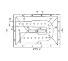
- FIG. 2 is a horizontal cross-sectional view of the FOG disposal unit of FIG. 1 ;
- FIG. 3 is a side elevation view of the FOG disposal unit of FIG. 1 ;
- FIG. 4 is a back end view of the FOG disposal unit of FIG. 1 ;
- FIG. 5 is a front view of the FOG disposal unit of FIG. 1 ;
- FIG. 6 is a top view of the FOG disposal unit of FIG. 1 ;
- FIG. 7 is a bottom view of the FOG disposal unit of FIG. 1 ;
- FIG. 8 is a bottom view of a collection head according to one embodiment
- FIG. 9 is an isometric view of another embodiment of a collection head.
- FIG. 10 is a side view of another embodiment of a FOG disposal unit.
- FIG. 11 is a side view of yet another embodiment of a FOG disposal unit.
- the FOG disposal unit 10 comprises an enclosure 12 having a top 14 and a bottom 16 that forms a closed container.
- the enclosure top 14 and bottom 16 are fastened together by way of mating top and bottom flanges 18 that are fastened together with bolts 20 , or the like.
- An elastomeric or other suitable seal (not shown) is located between the flanges 18 .
- the bolts 20 can be removed to allow the top 14 to be separated from the bottom 16 .
- the top 14 and bottom 16 can be hinged together at one edge with a hinge.
- the top 14 and bottom 16 of the enclosure 12 can be constructed from a stainless steel metal, fiberglass, or other suitable material that is resistant to rust and deterioration when subject to waste liquids typically encountered in kitchens and food processing plants.
- the FOG disposal unit 10 can be constructed with four legs, one shown as numeral 19 , to support the unit 10 in an upright position, as shown, on the floor or bottom shelf of a cabinet in which a sink is situated. Thus, the waste liquid from the sink can be drained by gravity directly into the FOG disposal unit 10 . Similarly, for sinks that are equipped with a garbage disposal unit, the output thereof can be connected to the inlet 22 of the FOG disposal unit 10 .
- a typical U-shaped drain trap can be omitted because it is not necessary, as the FOG disposal unit 10 functions as a conventional trap to prevent gasses from passing therethrough and into the kitchen.
- the generalized operation of the FOG disposal unit 10 includes the coupling of the waste liquid to the inlet 22 , and then to a perforated baffle tube 24 .
- the length of the baffle tube 24 is sufficient so that after a resident time therein, the liquefied grease and oil rise and exit the baffle tube 24 and move to the top of the FOG disposal unit 10 .
- the baffle tube 24 thus constitutes a primary separation area of the FOG disposal unit 10 .
- the liquefied grease and oil are lighter in density than water and thus rise and collect in an oil reservoir 40 , which is located at the top of the unit 10 . During use, the oil and liquefied grease in the oil reservoir 40 continue to accumulate until drained off via the manually-operated valve 42 .
- vent 44 Attached to the top of the oil reservoir 40 is the vent 44 which allows air entrained in the influent to escape from the FOG disposal unit 10 .
- the vent 44 as well as the pipe rising from the oil reservoir, is of a small cross-sectional area so as not to reduce the hydraulic or hydrostatic forces generated within the enclosure 12 when waste liquids are drained therein.
- a feature of the vent 44 is the larger diameter expansion chamber 78 which serves to prevent escaping air bubbles from propelling the liquid oil up and out of the vent 44 .
- the solids carried in the waste liquid gravitate to the bottom of the baffle tube 24 and exit via perforations in the bottom thereof, and to the floor of the enclosure bottom 16 .
- An outlet pipe 46 extends to the enclosure bottom 16 and terminates in a collection head 48 which causes the velocity of the water pulled therethrough to increase, thereby lifting the solids from the floor of the enclosure bottom 16 upwardly and coupled to a discharge outlet 50 and out of the FOG disposal unit 10 .
- a collection head 48 which causes the velocity of the water pulled therethrough to increase, thereby lifting the solids from the floor of the enclosure bottom 16 upwardly and coupled to a discharge outlet 50 and out of the FOG disposal unit 10 .
- the enclosure 12 of the unit 10 is full of liquids during normal operation. While waste water and solids are disposed of every time waste liquids are drained from the sink, the liquefied grease and oil continues to accumulate in the FOG disposal unit 10 until drained off via the valve 42 . As such, during operation, the liquid interface between the waste water and the overlying FOG liquid moves downwardly in the FOG disposal unit 10 .
- the baffle tube 24 is thus always immersed in the waste liquid in the unit 10 , and preferably in the waste water portion so that the liquefied grease and oil can move upwardly through the waste water and be collected at the top of the FOG disposal unit 10 .
- the enclosure bottom 16 of the FOG disposal unit 10 includes the tubular inlet 22 connected to the U-shaped baffle tube 24 by a coupling 26 .
- the inlet 22 is positioned high on the enclosure bottom 16 , and is secured to the sidewall to support the baffle tube 24 which is positioned generally centrally between the vertical sidewalls of the enclosure bottom 16 .
- the baffle tube 24 is a perforated enclosure and is constructed with graduated diameters, namely, an inlet smaller diameter section 28 located near the inlet 22 , a larger diameter mid-section 30 which is U-shaped, and a further larger diameter end section 32 located at the end. This is shown in FIG. 2 .
- the volume of the baffle tube 24 is thus a function of its length.
- the end section 32 is equipped with a cap 34 to prevent waste liquids and solids from escaping from the end of the baffle tube 24 .
- the tube can be constructed with a cone shape where the diameter is gradually larger as a function of the length of the cone.
- the baffle tube 24 is perforated and constructed of a PVC type of plastic or other suitable type of metal or synthetic material.
- the baffle tube 24 is fabricated with a number of holes, slots or other shaped perforations on both the top surface and on the bottom surface.
- the holes 36 are shown formed in the top surface of the baffle tube 24
- holes 38 are shown formed in the bottom surface of the baffle tube 24 .
- the size of the top holes 36 is not critical, but are of sufficient size to allow liquid grease and oil to rise and exit the baffle tube 24 .
- the length of the baffle tube 24 is sufficient to provide a residence time that allows the immiscible liquids to separate. It has been found that the residence time of waste liquids in the baffle tube 24 should be about 27 seconds for kitchen type wastes.
- the baffle tube 24 can also be circular, coiled in a spiral, serpentine or any other suitable shape. It can be appreciated that when the waste liquid enters the unit 10 , the large droplets of FOG start to separate in the frontal baffle tube section 28 and, for the most part, the remaining immiscible liquid is separated when they reach the end 34 of the baffle tube section 32 . The immiscible liquids that do not separate in the primary separation chamber, i.e., the baffle tube 24 , exit therefrom and are separated in the secondary chamber. In order to allow the liquefied grease and oil to exit at every location in the baffle tube 24 , the baffle tube 24 includes perforations or holes 36 all along the length thereof.
- the holes 38 formed along the length of the bottom of the baffle tube 24 are more critical, in that they must be large enough to pass the particulate matter generally found in kitchen waste water. In the event a motor-driven garbage disposal unit is attached to the sink drain, then the size of the particulate matter would be smaller and thus the bottom holes 38 could be smaller. In any event, the size of the particulate matter holes 38 can be determined experimentally for different applications.
- the diameter of the baffle tube 24 gradually increases in size from the front to the back thereof. With an increased size of the baffle tube 24 as the waste liquid moves therein, the waste liquid tends to be less turbulent, thereby allowing the immiscible liquids to separate more efficiently. It can be appreciated that the separation of immiscible liquids is facilitated when the turbulence therein is minimized.
- FIG. 7 a bottom view of the FOG disposal unit 10 is illustrated.
- the enclosure bottom 16 terminates with slanted opposing front and back sides 56 and 58 , and with slanted opposing lateral sides 52 and 54 .
- the four slanted sides 52 - 58 converge downwardly to a V-shaped collection throat 60 at the enclosure bottom.
- the slanted sides 52 - 58 facilitate the movement of solids downwardly in the enclosure bottom 16 to the collection throat 60 . It has been experimentally found that an effective slanting of the sides 52 - 58 is about forty-five degrees, or greater. However, other angles can be utilized.
- a vibrator can be attached to the outer surface of one or more of the slanted sides to assist the movement of solids to the V-shaped collection throat 60 .
- FIG. 8 illustrates one embodiment of the water/solids collection head 48 that lies adjacent the collection throat 60 formed along the elongate juncture of the slanted sides 52 - 58 .
- the collection head 48 can be constructed of a tubular PVC pipe connected via a T to the outlet pipe 46 .
- the tubular pipe collection head 48 may or may not be capped at both ends, and includes a bottom slot 62 along its length.
- the slot 62 defines a restriction, or elongate orifice, to the flow of waste water therethrough.
- the bottom of the collection head 48 is held close to the collection throat 60 to optimize the force of the suction. However, the collection head 48 should be spaced sufficiently from the collection throat 60 and the opposing slanted sides 52 and 54 to allow the solids to pass therebetween and to the collection throat 60 . It is also noted that the outlet pipe 46 is of smaller diameter than the inlet pipe 22 to function as a restriction to the flow of liquid therethrough, thereby enhancing the suction created in the slot 62 or opening of the collection head 48 . As can be appreciated, every time waste liquids are coupled into the FOG disposal unit 10 via the inlet pipe 22 , the waste water and the solids are swept out of the bottom of the unit 10 . The user of the FOG disposal unit 10 thus does not need to empty any particulate matter from the unit 10 . It can also be appreciated that the particulate matter removed with the waste water is that matter which is heavier (greater density) than the liquefied grease and oil.
- the outlet pipe 46 extends upwardly within the enclosure 12 and empties into the discharge outlet 50 which is larger in diameter.
- the top end of the outlet pipe 46 is sealed within the discharge outlet 50 with an elastomeric or other suitable type of seal.
- the outlet pipe 46 and the water/solids collection head 48 are thus fastened to the enclosure top 14 of the FOG disposal unit 10 .
- the outlet pipe 46 and the water/solids collection head 48 can be removed with the enclosure top 14 .
- FIG. 9 illustrates another embodiment of a collection head 75 .
- the outlet pipe 46 is connected to a flared hood 77 that flares out to a length which is substantially the same as the length of the collection throat 60 .
- the hood 77 of the collection head 75 functions to funnel the suctioned waste water and entrained solids upwardly and into the outlet pipe 46 .
- the elongate inlet slot 79 at the bottom of the hood 77 functions as a restriction to thus accelerate the flow of liquids and solids therethrough.
- many other configurations of collection heads can be fabricated by those skilled in the art.
- the enclosure top 14 of the FOG disposal unit 10 is constructed with a roof 70 that is inclined upwardly from the front of the unit 10 to the back thereof, with the front located at the inlet 22 .
- the FOG liquid tends to move to the top and rear of the unit 10 where the FOG outlet of the oil reservoir 40 is located.
- the oil reservoir generally occupies the top of the FOG disposal unit 10 , where the lighter weight FOG liquids are removed at the top back part of the unit 10 .
- the roof 70 of the enclosure top 14 is constructed with a raised part 72 into which the liquefied grease and oil can rise.
- the top of the raised part 72 is preferably lower than the waste water and solids discharged from the outlet 50 .
- the top of the raised part 72 includes an outlet port 74 connected to a T fitting 76 .
- the lateral outlet of the T fitting 76 is connected to the manually operated valve 42 .
- the top outlet of the T fitting 76 is connected to an expansion chamber 78 , and the outlet of the expansion chamber 78 is connected to the vent 44 .
- the lateral outlet of the T fitting 76 and thus the valve 42 , are preferably located at an elevation lower than the outlet pipe 50 . This allows the liquefied grease and oil to be drained from the reservoir 40 when the valve 42 is opened and when water is run into the sink and drained into the FOG disposal unit 10 . Otherwise, if the valve 42 were not located lower than the outlet pipe 50 , the water drained from the sink would simply run through the FOG disposal unit 10 and out of the discharge outlet 50 .
- the entrance area of the raised part 72 of the reservoir 40 is covered with a screen or perforated plate 80 to prevent turbulence in the secondary chamber of the unit 10 from disturbing the liquefied grease and oil in the raised part 72 of the reservoir 40 .
- the perforated plate 80 also prevents buoyant solids from entering the raised part 72 of the reservoir 40 .
- the valve 42 can be closed, the water tap turned off, and the waste container removed and properly disposed of.
- the unit 10 is then ready for continued use to separate the waste water and solids from the liquefied grease and oil.
- the only components of the waste liquid that is coupled to the utility drain is the waste water and the solids.
- the liquefied grease and oil are collected separately and properly disposed of without draining the same to the utility drain system.
- the FOG liquid can be drawn off via the valve 42 and into a cappable container, such as a plastic or other type of biodegradable container.
- the spout 82 can be of the type that has female threads to accept the externally threaded mouth of the disposable container.
- the spout 82 can be equipped with a small vent tube to vent the air out of the container when it is being filled via the opened valve 42 .
- vent line 44 since the outlet of the vent line 44 is located above the discharge outlet 50 , even an excessive amount of oil in the FOG disposal unit 10 will not overflow through the vent line 44 . Rather, an excessive amount of liquefied grease and oil will cause the interface between the waste water and the separated oil to be lowered in the enclosure 12 , and eventually flow out of the outlet pipe 46 via the water/solids head 48 . Thus, the failsafe state of one forgetting to empty the unit 10 of waste grease and oil is that the same will be coupled to the utility drain system, and not out of the vent line 44 and onto the floor or bottom shelf of the kitchen cabinet.
- the vent line 44 could easily be extended using a flexible tube within the kitchen cabinet. The top open end of the flexible tube would be at a level with the water level in a full sink. This would prevent fluids from being expelled even in the case of a blockage downstream from the separator unit 10 .
- a thermostatically-controlled heater 94 can be employed in the oil reservoir 40 .
- the heater 94 has a heating element immersed in the oil to maintain it at a temperature between about 100-102 degrees F. so that grease will not return to a solid state.
- the heater 94 can be of the electrical type that is plugged into a wall outlet, generally available below kitchen sinks.
- the bottom 16 of the enclosure 12 can be equipped with a drain plug 84 . If it is desired to open the unit 10 and clean the enclosure bottom 16 or replace components, the unit 10 can be partially drained via the plug 84 .
- the drain plug 84 can also be located at other locations in the enclosure bottom 16 , even on the slanted sides 52 - 58 .
- FIG. 10 illustrates another embodiment of a FOG disposal unit 81 .
- the unit 81 is substantially the same as that of FIGS. 1-7 , but additionally includes a liquefied grease and oil storage vessel 83 that holds a substantial volume of the liquefied wastes that are heavier than the waste water processed through the unit 81 .
- the storage vessel 83 is fastened to the enclosure 12 by means not shown. The waste grease and oil are forced into the storage vessel 83 via hydrostatic pressure in the enclosure 12 when waste liquids are drained therein from the sink.
- the waste grease and oil flow upwardly from the reservoir 40 through an upright pipe 96 and non-return valve 98 into the storage vessel 83 .
- the non-return valve 98 can be of many types, including a ball and cage type or flapper type.
- the liquefied grease and oil that have been transferred to the storage vessel 83 cannot return to the reservoir 40 of the enclosure 12 .
- a vent tube 99 extends out of the top of the storage vessel 83 to allow trapped or entrained air to escape.
- a manually-controlled valve 90 is provided to draw off the liquefied grease and oil from the storage vessel 83 .
- water is run from a faucet into the sink and thus into the unit 81 to facilitate the draining of liquefied grease and oil from the storage vessel 83 .
- a thermostatically-controlled heater can be used with the storage vessel 83 to maintain the grease and oil in a liquefied state.
- the storage vessel 83 also functions as a tertiary separator to separate any waste water from the heavier liquefied grease and oil contained therein. Any water content in the liquefied FOG material will gravitate to the bottom of the storage vessel 83 and be drained via a small diameter bleed line 92 back into the bottom 16 of the enclosure 12 .
- the small diameter bleed line 92 ensures that waste liquids drained into the enclosure 12 will cause the waste water and solids to be pushed out of the discharge outlet 50 , rather than up the bleed line 92 and into the FOG storage vessel 83 .
- draw-off valve 90 is located above a specified level of the storage vessel so that only the grease and oil is drained off, and not any water that has been separated from the liquefied grease and oil in the tertiary separator 83 . Also, the bottom of the storage vessel 83 is slanted down to a point where the bleed line 92 is connected thereto.
- FIG. 11 illustrates another embodiment of a FOG disposal unit 100 incorporating the principles and concepts of the invention. While not shown, the FOG disposal unit 100 is equipped with legs.
- the unit 100 includes an enclosure 102 that houses a primary separation chamber comprising a baffle tube 104 of the type described above.
- the waste liquid is input to the enclosure 102 via an inlet 106 .
- a collection head 108 is located adjacent a V-shaped floor 110 of the enclosure 102 to sweep the solids therefrom and transfer the same with the waste water upwardly in an outlet pipe 112 .
- the outlet pipe 112 is of reduced diameter as compared to inlet 106 to increase the velocity of the waste water carried therethrough.
- the increased velocity of the waste water in the collection head 108 is effective to suction or sweep the solids that have settled to the bottom of the enclosure 102 in the V-shaped floor 110 .
- the V-shaped floor 110 is slanted downwardly to allow the particulate matter to gravitate to the bottom point.
- the collection head 108 is also at an angle and adjacent the V-shaped floor 110 so that as the particulate matter gravitates down the V-shaped floor 110 , it will move closer to the outlet pipe 112 where the suction is the greatest, and be suctioned or swept away with the waste water up to the discharge outlet 122 .
- the enclosure 102 comprises a secondary separation chamber for the residual waste water to be separated from the FOG material.
- the FOG materials that rise to the top of the enclosure 102 move through the perforated baffle plate 114 into a first FOG storage area 116 .
- the first FOG storage area 116 is separated from a second FOG storage area 120 by a weir 118 .
- the top edge of the weir 118 is of an elevation substantially the same as the level of the waste water and solids flowing out of the effluent discharge pipe 122 . The level is shown by the broken line 124 .
- any air entrapped in the FOG liquid may be released in either the first storage area 116 or the second storage area 120 , and exit via the vent 132 .
- any water that may have been carried over by the FOG liquid into the second storage area 120 can be separated therein and be coupled down the internal return conduit 128 , which has a bottom end that terminates in the lower part of the enclosure 102 where waste water collects. Any residual water in the FOG liquid thus has an opportunity to be returned to the enclosure 102 and discharged out of the pipe 122 .
- FOG disposal apparatus for separating the waste water and solids from the FOG liquids.
- the waste water and solids settle to the bottom of the enclosure, and the FOG liquids are separated and rise to the top of the enclosure.
- An elongated path within a baffle tube facilitates the separation of the FOG liquids from the waste water and solids.
- a collection head at the bottom of the enclosure is structured to suction the waste water and solids therein, and carry the same to a discharge outlet.
- the FOG liquids are stored in a reservoir which is part of the FOG disposal unit. When it is desired to empty the FOG reservoir, then water is drained into the enclosure, which forces the FOG liquids out of the reservoir, via an opened valve. While the FOG disposal units have been disclosed for use in kitchens and other food processing plants, the principles and concepts of the invention can be applied to many other applications.
Abstract
Description
Claims (20)
Priority Applications (1)
| Application Number | Priority Date | Filing Date | Title |
|---|---|---|---|
| US13/374,274 US8900463B2 (en) | 2010-12-20 | 2011-12-20 | Self-disposal of solids in an immiscible liquid separator |
Applications Claiming Priority (2)
| Application Number | Priority Date | Filing Date | Title |
|---|---|---|---|
| US201061425141P | 2010-12-20 | 2010-12-20 | |
| US13/374,274 US8900463B2 (en) | 2010-12-20 | 2011-12-20 | Self-disposal of solids in an immiscible liquid separator |
Publications (2)
| Publication Number | Publication Date |
|---|---|
| US20120152864A1 US20120152864A1 (en) | 2012-06-21 |
| US8900463B2 true US8900463B2 (en) | 2014-12-02 |
Family
ID=46233001
Family Applications (1)
| Application Number | Title | Priority Date | Filing Date |
|---|---|---|---|
| US13/374,274 Active 2033-02-10 US8900463B2 (en) | 2010-12-20 | 2011-12-20 | Self-disposal of solids in an immiscible liquid separator |
Country Status (2)
| Country | Link |
|---|---|
| US (1) | US8900463B2 (en) |
| WO (1) | WO2012087351A1 (en) |
Cited By (4)
| Publication number | Priority date | Publication date | Assignee | Title |
|---|---|---|---|---|
| CN105289054A (en) * | 2015-11-02 | 2016-02-03 | 中盐工程技术研究院有限公司 | Solid-liquid separator |
| US10035716B1 (en) | 2015-08-21 | 2018-07-31 | Goslyn General, Llc | Immiscible liquid separator for marine vessels |
| US10300406B1 (en) | 2016-10-06 | 2019-05-28 | Gosyln General, Llc | Variable flow immiscible liquid separator for in-ground applications |
| US11255083B2 (en) | 2017-11-21 | 2022-02-22 | Thermaco, Incorporated | Solids transfer pump with modular components |
Families Citing this family (9)
| Publication number | Priority date | Publication date | Assignee | Title |
|---|---|---|---|---|
| ES2640925T3 (en) * | 2012-12-21 | 2017-11-07 | Seabed Separation As | Inclined tubular separator to separate substances from oil wells |
| CN103073091B (en) * | 2013-02-06 | 2014-09-17 | 山东华特磁电科技股份有限公司 | Oil-water separating device for separation and recovery of thin oil film |
| US10125034B2 (en) * | 2014-05-12 | 2018-11-13 | Erick Mcwayne | Permeable reactive weir |
| NL1040982B1 (en) * | 2014-10-03 | 2016-10-03 | Johanna Maria Van Vught Erna | Putvet purification. |
| CA3031078C (en) * | 2018-02-01 | 2023-07-25 | Daryl Beckingham | Waste oil handling apparatus |
| GB2585200B (en) | 2019-07-01 | 2023-11-01 | Mccabe Kevin | A device for removing fats, oils and/or grease (FOGs) from water |
| US10981088B2 (en) * | 2019-09-24 | 2021-04-20 | Kbk Industries, Llc | Sand collection and concentration tank |
| CN110975357B (en) * | 2019-12-26 | 2023-07-04 | 苏州仕净科技股份有限公司 | Industrial pure water preparation system for filtering and purifying |
| WO2023139488A1 (en) * | 2022-01-24 | 2023-07-27 | Eco Clarity Ltd. | A fog (fats, oils, or grease) separation apparatus |
Citations (39)
| Publication number | Priority date | Publication date | Assignee | Title |
|---|---|---|---|---|
| US1645093A (en) | 1923-10-24 | 1927-10-11 | White & Comyn Ltd | Oil separator |
| US1694668A (en) * | 1928-02-28 | 1928-12-11 | Guiberson Corp | Oil-tank baffle |
| US1741187A (en) * | 1929-12-31 | Clarxfier | ||
| US2642995A (en) | 1950-03-30 | 1953-06-23 | Josam Mfg Company | Outlet for grease separators and the like |
| US2732944A (en) * | 1956-01-31 | Sludge removing means | ||
| US3785126A (en) * | 1970-11-05 | 1974-01-15 | J Smitherman | Pollution control apparatus for smoke emitter |
| US3933654A (en) | 1972-06-21 | 1976-01-20 | Frederic R. Harris (Holland) B.V. | Oil separator for separating oil lighter than the purified liquid being in a very pure state |
| US4064054A (en) | 1976-12-22 | 1977-12-20 | Chevron Research Company | Apparatus for separating oil-water mixtures |
| US4113617A (en) | 1977-04-21 | 1978-09-12 | Fred Phillip Bereskin | Grease separator |
| US4123365A (en) | 1974-08-14 | 1978-10-31 | Ballast-Nedam Groep N.V. | Oil-water separator |
| US4406789A (en) * | 1980-04-21 | 1983-09-27 | Establissemens Andre Bardet S.A. | Apparatus and installation for separating immiscible liquids with different specific gravities |
| US4422931A (en) | 1982-04-15 | 1983-12-27 | Wolde Michael Girma | Oil concentrator |
| US5021153A (en) | 1989-11-20 | 1991-06-04 | G-H Systems, Inc. | Combined apparatus for removing grit and grease from sewage |
| US5435924A (en) * | 1994-02-16 | 1995-07-25 | Albertson; Orris E. | Sludge collection apparatus and method |
| US5494586A (en) | 1990-06-20 | 1996-02-27 | Toyota Jidosha Kabushiki Kaisha | Oil-water separation apparatus |
| US5505860A (en) | 1994-10-24 | 1996-04-09 | Sager; Robert J. | Grease and oil trap |
| US5552050A (en) * | 1993-08-30 | 1996-09-03 | Hans Huber Gmbh & Co. Kg | Device for the removal of clarified waste water from rectangular basins |
| US5705055A (en) | 1995-06-23 | 1998-01-06 | Josam Company | Apparatus for automatically recovering grease from a grease separator |
| US5837152A (en) * | 1997-04-09 | 1998-11-17 | Corlac Inc. | Inclined separation tank |
| US5840198A (en) | 1994-07-29 | 1998-11-24 | International Fluid Separation Pty Ltd | Separation apparatus and method |
| EP0890381A1 (en) | 1997-07-07 | 1999-01-13 | Allan Owen | Separator for immiscible liquids |
| US6371308B1 (en) * | 2000-09-14 | 2002-04-16 | Siping Zhou | Multiple stationary sludge draw-off tubes in clarifiers |
| US6491830B1 (en) | 2001-05-16 | 2002-12-10 | Thermaco, Inc. | Kitchen grease removal system |
| US20030024866A1 (en) | 2001-07-24 | 2003-02-06 | Jianmin Wang | Apparatus for treating water or wastewater |
| US6517715B1 (en) | 1999-11-12 | 2003-02-11 | Thermaco, Inc. | Readily serviceable separator unit with a focusing plate |
| US6551516B1 (en) | 1999-10-27 | 2003-04-22 | Schreiber Corporation, Inc. | Methods for removing grit and grease from water |
| US6645387B2 (en) * | 2001-02-15 | 2003-11-11 | Evac International Oy | Separator device |
| US20050016937A1 (en) * | 2003-07-21 | 2005-01-27 | Smullin Joseph I. | Separator of floating components |
| US6849176B1 (en) | 2003-09-04 | 2005-02-01 | Thermaco, Inc. | Grease separator for kitchen sinks and other applications |
| US6920984B2 (en) * | 2002-12-06 | 2005-07-26 | Warren Roy Agnew | Rainwater tank cleaning system |
| US6951615B2 (en) | 2003-03-25 | 2005-10-04 | Zurn Industries, Inc. | Grease removal system |
| US20060219629A1 (en) * | 2005-03-31 | 2006-10-05 | Andrew Noestheden | Oil and water separator |
| US7284670B2 (en) * | 2004-10-29 | 2007-10-23 | Aero-Mod, Inc. | Sedimentation removal assembly for flow-through sedimentary tank |
| US7297284B2 (en) | 2004-03-26 | 2007-11-20 | Goslyn, L.P. | Separator for immiscible liquids |
| US7331472B2 (en) | 2000-04-06 | 2008-02-19 | Lisopharm Ag | Method and apparatus for separation of a mixture of non-miscible liquids |
| US7431852B2 (en) | 2007-01-26 | 2008-10-07 | Thermaco, Inc. | Oil/grease separator with interchangeable inlet and outlet |
| US7540967B2 (en) | 2006-04-27 | 2009-06-02 | Thermaco, Inc. | Passive grease trap using separator technology |
| US7617940B2 (en) * | 2005-02-18 | 2009-11-17 | Norsk Hydro Asa | Arrangement related to a separator for the cleaning of such separator |
| US7682509B2 (en) | 2008-01-17 | 2010-03-23 | Green Turtle Americas Ltd. | Trap for removing material from a fluid stream |
-
2011
- 2011-12-20 WO PCT/US2011/001994 patent/WO2012087351A1/en active Application Filing
- 2011-12-20 US US13/374,274 patent/US8900463B2/en active Active
Patent Citations (40)
| Publication number | Priority date | Publication date | Assignee | Title |
|---|---|---|---|---|
| US1741187A (en) * | 1929-12-31 | Clarxfier | ||
| US2732944A (en) * | 1956-01-31 | Sludge removing means | ||
| US1645093A (en) | 1923-10-24 | 1927-10-11 | White & Comyn Ltd | Oil separator |
| US1694668A (en) * | 1928-02-28 | 1928-12-11 | Guiberson Corp | Oil-tank baffle |
| US2642995A (en) | 1950-03-30 | 1953-06-23 | Josam Mfg Company | Outlet for grease separators and the like |
| US3785126A (en) * | 1970-11-05 | 1974-01-15 | J Smitherman | Pollution control apparatus for smoke emitter |
| US3933654A (en) | 1972-06-21 | 1976-01-20 | Frederic R. Harris (Holland) B.V. | Oil separator for separating oil lighter than the purified liquid being in a very pure state |
| US4123365A (en) | 1974-08-14 | 1978-10-31 | Ballast-Nedam Groep N.V. | Oil-water separator |
| US4064054A (en) | 1976-12-22 | 1977-12-20 | Chevron Research Company | Apparatus for separating oil-water mixtures |
| US4113617A (en) | 1977-04-21 | 1978-09-12 | Fred Phillip Bereskin | Grease separator |
| US4406789A (en) * | 1980-04-21 | 1983-09-27 | Establissemens Andre Bardet S.A. | Apparatus and installation for separating immiscible liquids with different specific gravities |
| US4422931A (en) | 1982-04-15 | 1983-12-27 | Wolde Michael Girma | Oil concentrator |
| US5021153A (en) | 1989-11-20 | 1991-06-04 | G-H Systems, Inc. | Combined apparatus for removing grit and grease from sewage |
| US5494586A (en) | 1990-06-20 | 1996-02-27 | Toyota Jidosha Kabushiki Kaisha | Oil-water separation apparatus |
| US5552050A (en) * | 1993-08-30 | 1996-09-03 | Hans Huber Gmbh & Co. Kg | Device for the removal of clarified waste water from rectangular basins |
| US5435924A (en) * | 1994-02-16 | 1995-07-25 | Albertson; Orris E. | Sludge collection apparatus and method |
| US5840198A (en) | 1994-07-29 | 1998-11-24 | International Fluid Separation Pty Ltd | Separation apparatus and method |
| US5505860A (en) | 1994-10-24 | 1996-04-09 | Sager; Robert J. | Grease and oil trap |
| US5705055A (en) | 1995-06-23 | 1998-01-06 | Josam Company | Apparatus for automatically recovering grease from a grease separator |
| US5837152A (en) * | 1997-04-09 | 1998-11-17 | Corlac Inc. | Inclined separation tank |
| EP0890381A1 (en) | 1997-07-07 | 1999-01-13 | Allan Owen | Separator for immiscible liquids |
| US6551516B1 (en) | 1999-10-27 | 2003-04-22 | Schreiber Corporation, Inc. | Methods for removing grit and grease from water |
| US6517715B1 (en) | 1999-11-12 | 2003-02-11 | Thermaco, Inc. | Readily serviceable separator unit with a focusing plate |
| US7331472B2 (en) | 2000-04-06 | 2008-02-19 | Lisopharm Ag | Method and apparatus for separation of a mixture of non-miscible liquids |
| US6371308B1 (en) * | 2000-09-14 | 2002-04-16 | Siping Zhou | Multiple stationary sludge draw-off tubes in clarifiers |
| US6645387B2 (en) * | 2001-02-15 | 2003-11-11 | Evac International Oy | Separator device |
| US6491830B1 (en) | 2001-05-16 | 2002-12-10 | Thermaco, Inc. | Kitchen grease removal system |
| US20030024866A1 (en) | 2001-07-24 | 2003-02-06 | Jianmin Wang | Apparatus for treating water or wastewater |
| US6920984B2 (en) * | 2002-12-06 | 2005-07-26 | Warren Roy Agnew | Rainwater tank cleaning system |
| US6951615B2 (en) | 2003-03-25 | 2005-10-04 | Zurn Industries, Inc. | Grease removal system |
| US20050016937A1 (en) * | 2003-07-21 | 2005-01-27 | Smullin Joseph I. | Separator of floating components |
| US6849176B1 (en) | 2003-09-04 | 2005-02-01 | Thermaco, Inc. | Grease separator for kitchen sinks and other applications |
| US7153439B1 (en) | 2003-09-04 | 2006-12-26 | Thermaco, Inc. | Grease separator for kitchen sinks and other applications |
| US7297284B2 (en) | 2004-03-26 | 2007-11-20 | Goslyn, L.P. | Separator for immiscible liquids |
| US7284670B2 (en) * | 2004-10-29 | 2007-10-23 | Aero-Mod, Inc. | Sedimentation removal assembly for flow-through sedimentary tank |
| US7617940B2 (en) * | 2005-02-18 | 2009-11-17 | Norsk Hydro Asa | Arrangement related to a separator for the cleaning of such separator |
| US20060219629A1 (en) * | 2005-03-31 | 2006-10-05 | Andrew Noestheden | Oil and water separator |
| US7540967B2 (en) | 2006-04-27 | 2009-06-02 | Thermaco, Inc. | Passive grease trap using separator technology |
| US7431852B2 (en) | 2007-01-26 | 2008-10-07 | Thermaco, Inc. | Oil/grease separator with interchangeable inlet and outlet |
| US7682509B2 (en) | 2008-01-17 | 2010-03-23 | Green Turtle Americas Ltd. | Trap for removing material from a fluid stream |
Cited By (4)
| Publication number | Priority date | Publication date | Assignee | Title |
|---|---|---|---|---|
| US10035716B1 (en) | 2015-08-21 | 2018-07-31 | Goslyn General, Llc | Immiscible liquid separator for marine vessels |
| CN105289054A (en) * | 2015-11-02 | 2016-02-03 | 中盐工程技术研究院有限公司 | Solid-liquid separator |
| US10300406B1 (en) | 2016-10-06 | 2019-05-28 | Gosyln General, Llc | Variable flow immiscible liquid separator for in-ground applications |
| US11255083B2 (en) | 2017-11-21 | 2022-02-22 | Thermaco, Incorporated | Solids transfer pump with modular components |
Also Published As
| Publication number | Publication date |
|---|---|
| US20120152864A1 (en) | 2012-06-21 |
| WO2012087351A4 (en) | 2012-08-16 |
| WO2012087351A1 (en) | 2012-06-28 |
Similar Documents
| Publication | Publication Date | Title |
|---|---|---|
| US8900463B2 (en) | Self-disposal of solids in an immiscible liquid separator | |
| US6951615B2 (en) | Grease removal system | |
| EP1697049B1 (en) | Grease separator for kitchen sinks and other applications | |
| CA2299134C (en) | Wastewater separator and method of using same | |
| EP2516333A1 (en) | Separator for low discharge applications | |
| US20080149553A1 (en) | separator for immiscible liquids | |
| MX2012013929A (en) | Economical fat, oil, and grease waste removal system and method. | |
| WO2004022197A1 (en) | Sink with oil content recovery function | |
| US20060237362A1 (en) | Wastewater solids strainer apparatus for plumbing drain systems in commercial kitchen facilities | |
| US10300406B1 (en) | Variable flow immiscible liquid separator for in-ground applications | |
| WO2001063060A1 (en) | Wastewater separator and method of using same | |
| US10058798B2 (en) | Outlet well cover for an in-line grease interceptor | |
| US6402967B1 (en) | Grease separating device and method | |
| WO2009011660A1 (en) | Method and apparatus for the separation of grease and like contaminants | |
| US6143173A (en) | Removable drain filter | |
| AU2018371752B2 (en) | Solids transfer pump with modular components | |
| WO2020242459A1 (en) | Variable flow immiscible liquid separator for in-ground applications | |
| CN114890502A (en) | Oil-water separation device and method for intelligently classifying kitchen waste | |
| GB2599446A (en) | Waste water treatment apparatus | |
| CN109896646A (en) | A kind of home-use kitchen waste water filter device | |
| CA2974059A1 (en) | Method and system for management of sewer grease | |
| JPH06336307A (en) | Garbage force feeder | |
| AU7016898A (en) | Grease separating device |
Legal Events
| Date | Code | Title | Description |
|---|---|---|---|
| AS | Assignment |
Owner name: GOSLYN, L.P., TEXAS Free format text: ASSIGNMENT OF ASSIGNORS INTEREST;ASSIGNORS:SOWERBY, RICHARD H.;CARRERAS, RAFAEL A.;SOWERBY, JOHN C.;AND OTHERS;SIGNING DATES FROM 20111215 TO 20111219;REEL/FRAME:027596/0800 |
|
| STCF | Information on status: patent grant |
Free format text: PATENTED CASE |
|
| FEPP | Fee payment procedure |
Free format text: MAINTENANCE FEE REMINDER MAILED (ORIGINAL EVENT CODE: REM.) |
|
| FEPP | Fee payment procedure |
Free format text: SURCHARGE FOR LATE PAYMENT, SMALL ENTITY (ORIGINAL EVENT CODE: M2554); ENTITY STATUS OF PATENT OWNER: SMALL ENTITY |
|
| MAFP | Maintenance fee payment |
Free format text: PAYMENT OF MAINTENANCE FEE, 4TH YR, SMALL ENTITY (ORIGINAL EVENT CODE: M2551); ENTITY STATUS OF PATENT OWNER: SMALL ENTITY Year of fee payment: 4 |
|
| AS | Assignment |
Owner name: GOSLYN GENERAL, LLC, TEXAS Free format text: ASSIGNMENT OF ASSIGNORS INTEREST;ASSIGNOR:GOSLYN, LP;REEL/FRAME:047704/0237 Effective date: 20181206 |
|
| FEPP | Fee payment procedure |
Free format text: MAINTENANCE FEE REMINDER MAILED (ORIGINAL EVENT CODE: REM.); ENTITY STATUS OF PATENT OWNER: SMALL ENTITY |
|
| MAFP | Maintenance fee payment |
Free format text: PAYMENT OF MAINTENANCE FEE UNDER 1.28(C) (ORIGINAL EVENT CODE: M1559); ENTITY STATUS OF PATENT OWNER: LARGE ENTITY |
|
| FEPP | Fee payment procedure |
Free format text: 7.5 YR SURCHARGE - LATE PMT W/IN 6 MO, SMALL ENTITY (ORIGINAL EVENT CODE: M2555); ENTITY STATUS OF PATENT OWNER: SMALL ENTITY |
|
| MAFP | Maintenance fee payment |
Free format text: PAYMENT OF MAINTENANCE FEE, 8TH YR, SMALL ENTITY (ORIGINAL EVENT CODE: M2552); ENTITY STATUS OF PATENT OWNER: SMALL ENTITY Year of fee payment: 8 |
|
| MAFP | Maintenance fee payment |
Free format text: PAYMENT OF MAINTENANCE FEE UNDER 1.28(C) (ORIGINAL EVENT CODE: M1559); ENTITY STATUS OF PATENT OWNER: LARGE ENTITY |
|
| FEPP | Fee payment procedure |
Free format text: ENTITY STATUS SET TO UNDISCOUNTED (ORIGINAL EVENT CODE: BIG.); ENTITY STATUS OF PATENT OWNER: LARGE ENTITY |
|
| REFU | Refund |
Free format text: REFUND - PAYMENT OF MAINTENANCE FEE UNDER 1.28(C) (ORIGINAL EVENT CODE: R1559); ENTITY STATUS OF PATENT OWNER: LARGE ENTITY |