US8911580B2 - Method for producing a structural component - Google Patents
Method for producing a structural component Download PDFInfo
- Publication number
- US8911580B2 US8911580B2 US12/528,887 US52888708A US8911580B2 US 8911580 B2 US8911580 B2 US 8911580B2 US 52888708 A US52888708 A US 52888708A US 8911580 B2 US8911580 B2 US 8911580B2
- Authority
- US
- United States
- Prior art keywords
- holding part
- prepreg fabric
- unhardened
- structural component
- hardening temperature
- Prior art date
- Legal status (The legal status is an assumption and is not a legal conclusion. Google has not performed a legal analysis and makes no representation as to the accuracy of the status listed.)
- Active, expires
Links
Images


Classifications
-
- B—PERFORMING OPERATIONS; TRANSPORTING
- B29—WORKING OF PLASTICS; WORKING OF SUBSTANCES IN A PLASTIC STATE IN GENERAL
- B29C—SHAPING OR JOINING OF PLASTICS; SHAPING OF MATERIAL IN A PLASTIC STATE, NOT OTHERWISE PROVIDED FOR; AFTER-TREATMENT OF THE SHAPED PRODUCTS, e.g. REPAIRING
- B29C70/00—Shaping composites, i.e. plastics material comprising reinforcements, fillers or preformed parts, e.g. inserts
- B29C70/04—Shaping composites, i.e. plastics material comprising reinforcements, fillers or preformed parts, e.g. inserts comprising reinforcements only, e.g. self-reinforcing plastics
- B29C70/28—Shaping operations therefor
- B29C70/30—Shaping by lay-up, i.e. applying fibres, tape or broadsheet on a mould, former or core; Shaping by spray-up, i.e. spraying of fibres on a mould, former or core
- B29C70/34—Shaping by lay-up, i.e. applying fibres, tape or broadsheet on a mould, former or core; Shaping by spray-up, i.e. spraying of fibres on a mould, former or core and shaping or impregnating by compression, i.e. combined with compressing after the lay-up operation
- B29C70/342—Shaping by lay-up, i.e. applying fibres, tape or broadsheet on a mould, former or core; Shaping by spray-up, i.e. spraying of fibres on a mould, former or core and shaping or impregnating by compression, i.e. combined with compressing after the lay-up operation using isostatic pressure
-
- B—PERFORMING OPERATIONS; TRANSPORTING
- B29—WORKING OF PLASTICS; WORKING OF SUBSTANCES IN A PLASTIC STATE IN GENERAL
- B29C—SHAPING OR JOINING OF PLASTICS; SHAPING OF MATERIAL IN A PLASTIC STATE, NOT OTHERWISE PROVIDED FOR; AFTER-TREATMENT OF THE SHAPED PRODUCTS, e.g. REPAIRING
- B29C70/00—Shaping composites, i.e. plastics material comprising reinforcements, fillers or preformed parts, e.g. inserts
- B29C70/68—Shaping composites, i.e. plastics material comprising reinforcements, fillers or preformed parts, e.g. inserts by incorporating or moulding on preformed parts, e.g. inserts or layers, e.g. foam blocks
-
- B—PERFORMING OPERATIONS; TRANSPORTING
- B29—WORKING OF PLASTICS; WORKING OF SUBSTANCES IN A PLASTIC STATE IN GENERAL
- B29C—SHAPING OR JOINING OF PLASTICS; SHAPING OF MATERIAL IN A PLASTIC STATE, NOT OTHERWISE PROVIDED FOR; AFTER-TREATMENT OF THE SHAPED PRODUCTS, e.g. REPAIRING
- B29C70/00—Shaping composites, i.e. plastics material comprising reinforcements, fillers or preformed parts, e.g. inserts
- B29C70/04—Shaping composites, i.e. plastics material comprising reinforcements, fillers or preformed parts, e.g. inserts comprising reinforcements only, e.g. self-reinforcing plastics
- B29C70/28—Shaping operations therefor
- B29C70/54—Component parts, details or accessories; Auxiliary operations, e.g. feeding or storage of prepregs or SMC after impregnation or during ageing
- B29C70/543—Fixing the position or configuration of fibrous reinforcements before or during moulding
-
- B—PERFORMING OPERATIONS; TRANSPORTING
- B64—AIRCRAFT; AVIATION; COSMONAUTICS
- B64C—AEROPLANES; HELICOPTERS
- B64C1/00—Fuselages; Constructional features common to fuselages, wings, stabilising surfaces or the like
- B64C1/06—Frames; Stringers; Longerons ; Fuselage sections
- B64C1/12—Construction or attachment of skin panels
-
- B—PERFORMING OPERATIONS; TRANSPORTING
- B29—WORKING OF PLASTICS; WORKING OF SUBSTANCES IN A PLASTIC STATE IN GENERAL
- B29K—INDEXING SCHEME ASSOCIATED WITH SUBCLASSES B29B, B29C OR B29D, RELATING TO MOULDING MATERIALS OR TO MATERIALS FOR MOULDS, REINFORCEMENTS, FILLERS OR PREFORMED PARTS, e.g. INSERTS
- B29K2063/00—Use of EP, i.e. epoxy resins or derivatives thereof, as moulding material
-
- B—PERFORMING OPERATIONS; TRANSPORTING
- B29—WORKING OF PLASTICS; WORKING OF SUBSTANCES IN A PLASTIC STATE IN GENERAL
- B29K—INDEXING SCHEME ASSOCIATED WITH SUBCLASSES B29B, B29C OR B29D, RELATING TO MOULDING MATERIALS OR TO MATERIALS FOR MOULDS, REINFORCEMENTS, FILLERS OR PREFORMED PARTS, e.g. INSERTS
- B29K2105/00—Condition, form or state of moulded material or of the material to be shaped
- B29K2105/24—Condition, form or state of moulded material or of the material to be shaped crosslinked or vulcanised
- B29K2105/243—Partially cured
-
- B—PERFORMING OPERATIONS; TRANSPORTING
- B29—WORKING OF PLASTICS; WORKING OF SUBSTANCES IN A PLASTIC STATE IN GENERAL
- B29K—INDEXING SCHEME ASSOCIATED WITH SUBCLASSES B29B, B29C OR B29D, RELATING TO MOULDING MATERIALS OR TO MATERIALS FOR MOULDS, REINFORCEMENTS, FILLERS OR PREFORMED PARTS, e.g. INSERTS
- B29K2105/00—Condition, form or state of moulded material or of the material to be shaped
- B29K2105/24—Condition, form or state of moulded material or of the material to be shaped crosslinked or vulcanised
- B29K2105/246—Uncured, e.g. green
-
- B—PERFORMING OPERATIONS; TRANSPORTING
- B29—WORKING OF PLASTICS; WORKING OF SUBSTANCES IN A PLASTIC STATE IN GENERAL
- B29K—INDEXING SCHEME ASSOCIATED WITH SUBCLASSES B29B, B29C OR B29D, RELATING TO MOULDING MATERIALS OR TO MATERIALS FOR MOULDS, REINFORCEMENTS, FILLERS OR PREFORMED PARTS, e.g. INSERTS
- B29K2707/00—Use of elements other than metals for preformed parts, e.g. for inserts
- B29K2707/04—Carbon
-
- B—PERFORMING OPERATIONS; TRANSPORTING
- B29—WORKING OF PLASTICS; WORKING OF SUBSTANCES IN A PLASTIC STATE IN GENERAL
- B29K—INDEXING SCHEME ASSOCIATED WITH SUBCLASSES B29B, B29C OR B29D, RELATING TO MOULDING MATERIALS OR TO MATERIALS FOR MOULDS, REINFORCEMENTS, FILLERS OR PREFORMED PARTS, e.g. INSERTS
- B29K2709/00—Use of inorganic materials not provided for in groups B29K2703/00 - B29K2707/00, for preformed parts, e.g. for inserts
- B29K2709/08—Glass
-
- Y—GENERAL TAGGING OF NEW TECHNOLOGICAL DEVELOPMENTS; GENERAL TAGGING OF CROSS-SECTIONAL TECHNOLOGIES SPANNING OVER SEVERAL SECTIONS OF THE IPC; TECHNICAL SUBJECTS COVERED BY FORMER USPC CROSS-REFERENCE ART COLLECTIONS [XRACs] AND DIGESTS
- Y02—TECHNOLOGIES OR APPLICATIONS FOR MITIGATION OR ADAPTATION AGAINST CLIMATE CHANGE
- Y02T—CLIMATE CHANGE MITIGATION TECHNOLOGIES RELATED TO TRANSPORTATION
- Y02T50/00—Aeronautics or air transport
- Y02T50/40—Weight reduction
-
- Y02T50/43—
-
- Y02T50/433—
-
- Y—GENERAL TAGGING OF NEW TECHNOLOGICAL DEVELOPMENTS; GENERAL TAGGING OF CROSS-SECTIONAL TECHNOLOGIES SPANNING OVER SEVERAL SECTIONS OF THE IPC; TECHNICAL SUBJECTS COVERED BY FORMER USPC CROSS-REFERENCE ART COLLECTIONS [XRACs] AND DIGESTS
- Y10—TECHNICAL SUBJECTS COVERED BY FORMER USPC
- Y10T—TECHNICAL SUBJECTS COVERED BY FORMER US CLASSIFICATION
- Y10T156/00—Adhesive bonding and miscellaneous chemical manufacture
- Y10T156/10—Methods of surface bonding and/or assembly therefor
- Y10T156/1002—Methods of surface bonding and/or assembly therefor with permanent bending or reshaping or surface deformation of self sustaining lamina
Definitions
- This invention relates to a method for producing a structural component, particularly in the aerospace sector.
- a multiplicity of methods for producing a T-stringer stiffened skin is known from the state of the art.
- One of these methods provides that unhardened 1-stringers be arranged on an unhardened skin.
- the T-stringers and the skin are in this case each formed from carbon fibre plastic (CFC)-prepreg material.
- CFC carbon fibre plastic
- tools are provided for retaining the T-stringers in position on the skin before and during a subsequent hardening step, and in particular for preventing a “collapse” of the stringer web.
- the tools Since the CFC-prepreg material experiences hardly any variation in length at the hardening temperatures required for a high strength of the T-stringer-stiffened skin, ranging from approximately 125 to 180° C., because of its low thermal expansion coefficient, the tools must also be formed from a material which has such a low thermal expansion coefficient and also resists the hardening temperatures.
- the tools are therefore manufactured from special steel, which involves high costs.
- the costs result on the one hand from the high material price for the special steel itself, and on the other hand from the high expenditure involved in mechanical machining of the material to produce the tools.
- this object is achieved by a method with the characteristics of Claim 1 .
- an unhardened prepreg fabric is formed from a hardenable composite fibre material into a predetermined shape at a first hardening temperature.
- the unhardened prepreg fabric is connected to at least one holding part, hardened at least partially at a second hardening temperature, for retaining the unhardened prepreg fabric in the predetermined shape.
- the second hardening temperature is lower than the first hardening temperature.
- the unhardened prepreg fabric, connected to the at least one holding part is hardened to form the structural component at the first hardening temperature.
- the idea on which this invention is based consists in supplying a low cost, at least partially hardened holding part of composite fibre material for holding the prepreg fabric during hardening of the same, instead of the expensive tools of special steel.
- the at least one at least partially hardened holding part consists of a composite fibre material, which already hardens at a comparatively low hardening temperature. Therefore tools may also be provided for producing the at least one holding part from a material which has a comparatively high thermal expansion coefficient.
- the resultant flexibility in the choice of material enables a material which is both mechanically simple to machine and is relatively low cost, aluminium for example, to be used for the tools for producing the at least one holding part, with the result that only low costs are incurred in the production of the at least one holding part.
- the at least one holding part produced at low cost in this manner is then connected in a certain form to unhardened and hence dimensionally unstable prepreg fabric for holding it.
- the at least one holding part of composite fibre material also has the advantage that it has a very similar thermal expansion coefficient to that of the composite fibre material of the unhardened prepreg fabric. Consequently there are no harmful stresses between the prepreg fabric and the at least one holding part during hardening at the high hardening temperature.
- the first and second hardening temperatures each relate to a temperature at which a matrix of the composite fibre material of the prepreg fabric or the matrix of the composite fibre material of the at least one holding part is activated, i.e. a cross-linkage takes place between the macromolecular main chains of the respective matrix take place.
- a prepreg fabric of composite fibre material and a holding part of composite fibre material are understood in this context to consist of fibre structures, in particular tape fabrics, which preferably have a laminated structure.
- the fibres in the tape fabric are preferably designed in an optimised manner in terms of the loading of the structural component to be produced.
- the fibre structures and/or fibre fabrics are impregnated with a matrix, in particular an epoxy resin matrix.
- Forming of the unhardened prepreg fabric into a predetermined shape is preferably understood to mean the hot forming of the unhardened prepreg fabric. However, it is just as possible to carry out the “forming” into a certain shape by depositing the prepreg fabric on a predetermined geometry, for example a tool or on the at least one holding part itself.
- unhardened prepreg fabric is understood to mean a non-hardened, even wet prepreg fabric or also an only partially hardened prepreg fabric.
- the at least one holding part is connected in a firmly bonded manner, during the connection process, to the unhardened prepreg fabric, in the same plane in particular, to form an integral structural component.
- the holding part it would be conceivable to connect the holding part by means of suitable fixing means only, pins for example, to the unhardened prepreg fabric, and harden both in this condition.
- a very much more stable structural component can be achieved when the at least one holding part is connected in a firmly bonded manner to the unhardened prepreg fabric.
- the unhardened prepreg fabric is connected to the at least one holding part by pressing them together. This results in an advantageous embedding of the holding part in the prepreg fabric, due in particular to the matrix flow of the prepreg fabric thus achieved. A higher strength of the structural component to be produced is generally achieved.
- the at least one holding part is formed with an inner contour corresponding to an outer contour of the prepreg fabric to be formed before connection. Therefore contact over as large an area as possible, in particular a contiguous contact, can be achieved between the holding part and the prepreg fabric, and hence a particularly good support for the latter.
- the at least one holding part is formed, before connection, with a radius in a curved fashion, suitable recesses being cut into the at least one holding part to compensate for the material surplus resulting from a region that has been shortened relative to a neutral bending line.
- the neutral bending line generally defines the region of a curved body in which the material is neither extended nor shortened by bending.
- the shortened region lies on the side of the radius relative to the neutral bending line.
- the recesses for example in the form of approximately triangular incisions in the holding part, prevent buckling of a section of the holding part in the shortened region.
- the composite fibre material of the shortened regions, interrupted in sections due to the recesses, for example, can be connected to each other, in particular glued to each other.
- a curved holding part can be produced very easily by this method, which part may then be used to produce a structural component with a ramp.
- a further advantage of this is that the holding part itself can be formed in a curved manner without modifications to the tool for producing the holding part. The production costs may therefore be further reduced.
- the prepreg fabric is formed, before or during connection, as a profile, in particular as a T-profile composed of two L-profiles with a blade arranged between them, and/or the at least one holding part may be designed as a profile, in particular as an L-profile.
- a “profile” is understood to mean a component which extends in a spatial direction, described in the following as the “longitudinal direction”, with an essentially constant cross-section.
- a “blade” is understood to refer to reinforcing layers of composite fibre material which form a geometrically demarcated unit, particularly inside a stringer.
- the L-profiles of the prepreg fabric may first, for example, be deposited on a holding part designed as an L-profile.
- a blade is then arranged on one of the L-profiles of the prepreg fabric.
- the two holding parts are then pressed together and then retain the prepreg fabric between them.
- a structural component designed as a T-profile can be easily produced in this manner.
- two holding parts are provided which receive the prepreg fabric between them.
- receiving refers to receiving in sections, or even to its full extent. This therefore enables the prepreg fabric which is still dimensionally unstable to be supported.
- the two holding parts are brought into contact with each other at least in sections. Therefore the space between the two holding parts, to be occupied by the hardened prepreg fabric in particular, can be precisely defined.
- the unhardened prepreg fabric connected to the at least one holding part, is arranged before hardening on a skin of composite fibre material in particular, the prepreg fabric and/or the at least one holding part being brought into contact with the skin.
- a stringer-stiffened skin can therefore be produced, the skin supporting the prepreg fabric on one side and the at least one holding part in particular supporting one web of the prepreg fabric.
- a matrix of the prepreg fabric is provided with a hot hardener, in particular diaminodiphenyl sulphone, which hardens within a temperature range of between 110 and 200° C. in particular, and/or a matrix of the at least one holding part is provided with a cold hardener, in particular isophorone diamine or a cold hardener on an anhydrite basis, which hardens within a temperature range of between 20 and 100° C. in particular.
- a hot hardener in particular diaminodiphenyl sulphone
- a matrix of the at least one holding part is provided with a cold hardener, in particular isophorone diamine or a cold hardener on an anhydrite basis, which hardens within a temperature range of between 20 and 100° C. in particular.
- the desired properties of the structural component in terms of strength can be achieved with the hot hardener, whilst low cost production of the structural component is achieved with the cold hardener sine a low cost material
- the composite fibre material of the prepreg fabric has carbon fibres and/or the composite fibre material of the at least one holding part has glass fibres and/or carbon fibres and/or natural fibres.
- the carbon fibres of the holding part are preferably highly favourable fibres because they are not high quality. Therefore a structural component with the desired high strength can be obtained, whilst the holding part can be produced at low cost. If the holding part is formed from GFP, there is the added advantage that the notch bar impact strength of the structural component is increased. There is also improved corrosion protection and protection from lighting strikes in cases where the structural part is connected to metal connection elements.
- the structural component is preferably designed as a stringer, a rib or a skin with at least one stringer or at least one rib.
- FIG. 1 shows in a cross-sectional view a method condition of a method according to an exemplary embodiment of this invention
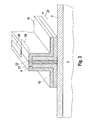
- FIG. 2 shows in a cross-sectional view a method condition of a method according to a further exemplary embodiment of this invention
- FIG. 3 shows in a perspective cross-sectional view a method condition of a method according to a further exemplary embodiment of this invention
- FIG. 4 shows in a cross-sectional view a method condition of a method according to yet a further exemplary embodiment of this invention
- FIG. 5A shows in a perspective view a method condition of a method according to yet a further exemplary embodiment of this invention.
- FIG. 5B shows in a perspective view a further method condition according to the exemplary embodiment in FIG. 5A .
- FIG. 1 shows, in a cross-sectional view, a method condition of a method according to an exemplary embodiment of this invention.
- An arrangement 1 has a skin 2 , preferably of non-hardened CFC, which is arranged on a lamination device 3 .
- skin 2 On its upper side 4 skin 2 is in firmly bonded contact with a foot 5 a , 5 b of an unhardened prepreg fabric 6 , which has a T-shaped cross-section.
- Unhardened prepreg fabric 6 was produced by pressing two mirror symmetrical L-profiles 7 , 8 , preferably each of unhardened CFC tape fabric having an epoxy resin matrix, with a blade 9 arranged between them, preferably also of unhardened CFC tape fabric having an epoxy resin matrix. Blade 9 forms, with two legs 10 , 11 of L-profiles 7 and 8 respectively, a web 5 c of prepreg fabric 6 .
- L-profiles 7 , 8 of prepreg fabric 6 itself were preferably brought into the L-shape shown by hot forming.
- Prepreg 6 is still in a dimensionally unstable condition.
- two dimensionally stable holding parts 12 , 13 which are preferably each designed as a L-profile of at least partially hardened GFP (glass fibre plastic), are provided so that they are mirror symmetrical.
- Web 5 c of prepreg fabric 6 in particular is in this case supported by holding parts 12 , 13 .
- an outer contour 14 , 15 of L-profiles 7 and 8 respectively of prepreg fabric 6 is brought into firmly bonded contact with an inner contour 16 and 17 of holding parts 12 and 13 respectively.
- Holding parts 12 , 13 are produced by means of a tool of aluminium or an aluminium alloy at a hardening temperature of approximately 80° C., with activation of a cold hardener, for example isophorone diamine. Holding parts 12 , 13 preferably have in this case a structure of two layers of glass fibre fabric which are impregnated with an epoxy resin matrix comprising the cold hardener.
- FIG. 1 To form the structural component arrangement 1 in FIG. 1 is packed into a vacuum bag and hardened in the autoclave, for example (not shown). The hardening takes place in the autoclave at approximately 180° C., a suitable hot hardener, for example diaminodiphenyl sulphone, being hardened in the matrix of prepreg fabric 6 or of L-profiles 7 , 8 and of blade 9 .
- a suitable hot hardener for example diaminodiphenyl sulphone
- the structural component produced is then similar to arrangement 1 shown in FIG. 1 , but all components 2 , 6 , 12 , 13 are hardened and are connected solidly to each other in one piece, forming a stringer on a skin.
- FIG. 2 differs from that in FIG. 1 in that holding parts 12 , 13 are designed as Z-profiles with web 12 c and 13 c extending perpendicularly to feet 12 a , 12 b and 13 a , 13 b respectively.
- holding parts 12 , 13 are brought into contact with each other at their end 21 , 22 assigned to feet 12 b , 13 b , preferably in the region of web 5 c and blade 9 of prepreg fabric 6 .
- this contact can also be brought about in sections only according to the exemplary embodiment in FIG. 2 .
- Ends 21 , 22 of holding parts 12 , 13 are in this case in contact in longitudinal direction 23 along a section 24 , whilst they are recessed in a section 25 connecting to section 24 in longitudinal direction 23 .
- This also provides the advantage, already described, that holding elements 12 , 13 occupy a defined distance to each other and material and hence weight can be saved at the same time.
- the exemplary embodiment according to FIG. 4 differs from that shown in FIG. 2 in that blade 9 extends between ends 21 , 22 , ends 21 , 22 being in contact with the blade. This guarantees a constant distance between holding parts 12 , 13 .
- FIG. 5A shows an L-profile 26 of at least partially hardened GFP with legs 31 , 32 , triangular recesses (denoted by way of example by reference symbol 33 ) are cut from leg 31 .
- L-profile 26 is curved about a radius 34 .
- a neutral bending line 35 extends essentially in the plane of leg 32 .
- Recesses 33 closed in the curved condition of L-profile 36 , are then glued to produce a stable L-profile 26 , which can then be used as holding part 12 or 13 according to the above exemplary embodiments.
- a non-impregnated fibre moulding may be used instead of an unhardened prepreg fabric, which moulding is not impregnated with a matrix having a hot hardener and is then hardened until after it has been connected to at least one holding part at least partially hardened by means of a cold hardener for holding the fibre moulding in a predetermined shape or has been arranged inside the same.
- This invention provides a method for producing a structural component, in particular in the aerospace sector, with the following method steps.
- An unhardened prepreg fabric is first formed from a composite fibre material hardenable at a first hardening temperature into a predetermined shape.
- the unhardened prepreg fabric is then connected to at least one holding part of a composite fibre material partially hardened at a second hardening temperature for holding the unhardened prepreg fabric in the predetermined shape, the second hardening temperature being lower than the first hardening temperature.
- the unhardened prepreg fabric connected to the at least one holding part is hardened to form the structural component at the first hardening temperature.
- the idea forming the basis of this invention consists in replacing expensive tools of special steel previously used for holding dimensionally unstable prepreg fabrics with at least one holding part of composite fibre material, the at least one holding part having a lower hardening temperature than the prepreg fabric and therefore able to be produced by means of a lower cost tool.
Abstract
Description
- 1 Arrangement
- 2 Skin
- 3 Laminating device
- 4 Surface
- 5 a Foot
- 5 b Foot
- 5 c Web
- 6 Prepreg fabric
- 7L-profile
- 8 L-profile
- 9 Blade
- 12 Holding part
- 12 a Foot
- 12 b Foot
- 12 c Web
- 13 Holding part
- 13 a Foot
- 13 b Foot
- 13 c Web
- 14 Outer contour
- 15 Outer contour
- 16 Inner contour
- 17 Inner contour
- 21 End
- 22 End
- 23 Longitudinal direction
- 24 Section
- 25 Section
- 26 L-profile
- 31 Leg
- 32 Leg
- 33 Recess
- 34 Radius
- 35 Bending line
Claims (34)
Priority Applications (1)
| Application Number | Priority Date | Filing Date | Title |
|---|---|---|---|
| US12/528,887 US8911580B2 (en) | 2007-03-30 | 2008-03-26 | Method for producing a structural component |
Applications Claiming Priority (6)
| Application Number | Priority Date | Filing Date | Title |
|---|---|---|---|
| US92100707P | 2007-03-30 | 2007-03-30 | |
| DE102007015517 | 2007-03-30 | ||
| DE102007015517.6 | 2007-03-30 | ||
| DE102007015517A DE102007015517A1 (en) | 2007-03-30 | 2007-03-30 | Process for producing a structural component |
| US12/528,887 US8911580B2 (en) | 2007-03-30 | 2008-03-26 | Method for producing a structural component |
| PCT/EP2008/053539 WO2008119701A1 (en) | 2007-03-30 | 2008-03-26 | Method for producing a structural component |
Publications (2)
| Publication Number | Publication Date |
|---|---|
| US20100139847A1 US20100139847A1 (en) | 2010-06-10 |
| US8911580B2 true US8911580B2 (en) | 2014-12-16 |
Family
ID=39719537
Family Applications (1)
| Application Number | Title | Priority Date | Filing Date |
|---|---|---|---|
| US12/528,887 Active 2030-12-24 US8911580B2 (en) | 2007-03-30 | 2008-03-26 | Method for producing a structural component |
Country Status (9)
| Country | Link |
|---|---|
| US (1) | US8911580B2 (en) |
| EP (1) | EP2129510B1 (en) |
| JP (1) | JP2010523357A (en) |
| CN (2) | CN101674927A (en) |
| BR (1) | BRPI0809550A2 (en) |
| CA (1) | CA2679078A1 (en) |
| DE (1) | DE102007015517A1 (en) |
| RU (1) | RU2457113C2 (en) |
| WO (1) | WO2008119701A1 (en) |
Cited By (3)
| Publication number | Priority date | Publication date | Assignee | Title |
|---|---|---|---|---|
| US9849965B2 (en) | 2013-07-12 | 2017-12-26 | Mitsubishi Heavy Industries, Ltd. | Manufacturing method of reinforced structure |
| US9856009B2 (en) | 2013-07-12 | 2018-01-02 | Mitsubishi Heavy Industries, Ltd. | Manufacturing method of reinforcing structure |
| US10173380B2 (en) | 2016-05-20 | 2019-01-08 | Cotesa Gmbh | Arcuate fiber composite plastic preform and method for production of curved profiles |
Families Citing this family (21)
| Publication number | Priority date | Publication date | Assignee | Title |
|---|---|---|---|---|
| DE102009033444A1 (en) * | 2009-07-16 | 2011-01-27 | Airbus Operations Gmbh | Shell segment for producing a fuselage cell section for a fuselage cell of an aircraft |
| DE102009051460B4 (en) | 2009-10-30 | 2012-12-13 | Audi Ag | Method for producing a multi-shell structural part having a hollow profile |
| GB2505435B (en) * | 2012-08-29 | 2015-08-19 | Gkn Aerospace Services Ltd | An apparatus and method for stiffeners |
| ES2799179T3 (en) * | 2014-03-06 | 2020-12-15 | Airbus Defence & Space Gmbh | Fibrous composite component with radiation cross-linked filler body |
| DE102014114012B4 (en) * | 2014-09-26 | 2022-12-29 | Deutsches Zentrum für Luft- und Raumfahrt e.V. | Method for manufacturing a fiber composite component |
| CN106738504B (en) * | 2016-11-30 | 2019-05-28 | 江西洪都航空工业集团有限责任公司 | A kind of preparation method for the composite material Z-pin enhancing equal pressing plate of reinforcement sheet metal forming |
| DE102016125958A1 (en) * | 2016-12-30 | 2018-07-05 | Airbus Operations Gmbh | Tool for molding a T-shaped semifinished product |
| US10253643B2 (en) | 2017-02-07 | 2019-04-09 | General Electric Company | Airfoil fluid curtain to mitigate or prevent flow path leakage |
| US10385709B2 (en) | 2017-02-23 | 2019-08-20 | General Electric Company | Methods and features for positioning a flow path assembly within a gas turbine engine |
| US10247019B2 (en) | 2017-02-23 | 2019-04-02 | General Electric Company | Methods and features for positioning a flow path inner boundary within a flow path assembly |
| US10378373B2 (en) | 2017-02-23 | 2019-08-13 | General Electric Company | Flow path assembly with airfoils inserted through flow path boundary |
| US10385776B2 (en) | 2017-02-23 | 2019-08-20 | General Electric Company | Methods for assembling a unitary flow path structure |
| US10370990B2 (en) | 2017-02-23 | 2019-08-06 | General Electric Company | Flow path assembly with pin supported nozzle airfoils |
| US10253641B2 (en) | 2017-02-23 | 2019-04-09 | General Electric Company | Methods and assemblies for attaching airfoils within a flow path |
| US10385731B2 (en) | 2017-06-12 | 2019-08-20 | General Electric Company | CTE matching hanger support for CMC structures |
| US10746035B2 (en) | 2017-08-30 | 2020-08-18 | General Electric Company | Flow path assemblies for gas turbine engines and assembly methods therefore |
| CN107825727B (en) * | 2017-10-20 | 2020-01-03 | 中国商用飞机有限责任公司北京民用飞机技术研究中心 | Method and device for forming preformed stringer L-shaped component and wallboard |
| DE102018009332A1 (en) * | 2018-11-28 | 2020-05-28 | Senvion Gmbh | Rotor blade with belts with deformable pultrudates |
| CN109732946B (en) * | 2019-02-14 | 2021-06-04 | 上海电气风电集团股份有限公司 | Preparation process of wind power blade with blade root prefabricated part |
| US11377851B2 (en) * | 2020-02-05 | 2022-07-05 | The Boeing Company | Stringer and associated composite structure and method for reinforcing a base structure |
| US11268394B2 (en) | 2020-03-13 | 2022-03-08 | General Electric Company | Nozzle assembly with alternating inserted vanes for a turbine engine |
Citations (20)
| Publication number | Priority date | Publication date | Assignee | Title |
|---|---|---|---|---|
| US4076869A (en) * | 1970-10-23 | 1978-02-28 | Ciba-Geigy Corporation | Hardenable epoxy resin compositions and process for making the same |
| JPH01204922A (en) | 1988-02-10 | 1989-08-17 | Showa Highpolymer Co Ltd | Curable resin and its preparation and application |
| RU2030336C1 (en) | 1991-03-05 | 1995-03-10 | Евгений Григорьевич Сабадаш | Method of manufacture of hollow bearing-wall skeleton structures |
| US5401349A (en) * | 1992-02-17 | 1995-03-28 | Basf Aktiengesellschaft | Production of shaped articles |
| JPH08258162A (en) | 1995-03-17 | 1996-10-08 | Mitsubishi Rayon Co Ltd | Integrally molding method for complicated structure |
| JPH10128860A (en) | 1996-10-30 | 1998-05-19 | Honda Motor Co Ltd | Manufacture of fiber-reinforced plastic molded product |
| US5876546A (en) * | 1997-09-25 | 1999-03-02 | The Boeing Company | Method for forming inner mold line tooling without a part model |
| DE19832441C1 (en) | 1998-07-18 | 2000-01-05 | Daimler Chrysler Aerospace | Stringer-reinforced shell production with double curvature using fibrous composite materials, without risk of warping |
| EP1149687A2 (en) | 2000-04-27 | 2001-10-31 | Honda Giken Kogyo Kabushiki Kaisha | Method for producing body structure of fiber-reinforced composite, and body structure produced thereby |
| WO2002066235A1 (en) | 2001-01-16 | 2002-08-29 | Lockheed Martin Corporation | Forming structural assemblies with 3-d woven joint pre-forms |
| JP2003053851A (en) | 2001-08-10 | 2003-02-26 | Toray Ind Inc | Method for manufacturing skin-stringer structure member made of cfrp |
| WO2004018186A1 (en) | 2002-08-20 | 2004-03-04 | Mitsubishi Rayon Co.,Ltd. | Method of producing formed product of fiber-reinforced composite material and the formed product |
| JP2005125558A (en) | 2003-10-22 | 2005-05-19 | Toyota Motor Corp | Molding method for frp hollow structure and core used therein |
| WO2006131532A1 (en) | 2005-06-07 | 2006-12-14 | Airbus Deutschland Gmbh | Method for manufacturing a reinforced shell for forming component parts for aircraft and shell for component parts for aircraft |
| DE602004002262T2 (en) | 2003-12-04 | 2007-04-05 | Airbus France | Method of arranging pre-impregnated parts for a self-stiffening composite panel |
| EP1800842A1 (en) | 2005-12-20 | 2007-06-27 | Saab Ab | A method of manufacturing an elongate structural element configured for stiffening a shell structure, and a method for manufacturing a rigid shell structure integrated with at least one elongate stiffening element |
| WO2007074178A1 (en) | 2005-12-29 | 2007-07-05 | Airbus España, S.L. | Method for producing structures from composite materials, including embedded precured tools |
| US7293737B2 (en) * | 2004-04-20 | 2007-11-13 | The Boeing Company | Co-cured stringers and associated mandrel and fabrication method |
| WO2008012378A1 (en) | 2006-07-28 | 2008-01-31 | Airbus España, S.L. | Method for producing pieces of compound materials with two curing cycles |
| DE102006045633A1 (en) | 2006-09-27 | 2008-04-03 | Airbus Deutschland Gmbh | Uncured stringer e.g. double T-shaped support, joining method, for e.g. aircraft, involves precuring/curing auxiliary material at specific temperature to form supporting units for web flanks, curing uncured stringer, and removing material |
Family Cites Families (3)
| Publication number | Priority date | Publication date | Assignee | Title |
|---|---|---|---|---|
| JPS59129119A (en) * | 1983-01-17 | 1984-07-25 | Mitsubishi Heavy Ind Ltd | Forming method of composite material product |
| WO2006112823A1 (en) * | 2005-04-13 | 2006-10-26 | The Boeing Company | Method to eliminate undulations in a composite panel |
| CA2619767C (en) * | 2005-08-19 | 2013-05-28 | Airbus Espana, S.L. | Stringers made of a composite material with a bulb |
-
2007
- 2007-03-30 DE DE102007015517A patent/DE102007015517A1/en not_active Ceased
-
2008
- 2008-03-26 CN CN200880010120A patent/CN101674927A/en active Pending
- 2008-03-26 JP JP2010500255A patent/JP2010523357A/en active Pending
- 2008-03-26 US US12/528,887 patent/US8911580B2/en active Active
- 2008-03-26 CN CN201510081880.4A patent/CN104690988B/en active Active
- 2008-03-26 RU RU2009132007/05A patent/RU2457113C2/en not_active IP Right Cessation
- 2008-03-26 EP EP08735479A patent/EP2129510B1/en not_active Not-in-force
- 2008-03-26 WO PCT/EP2008/053539 patent/WO2008119701A1/en active Application Filing
- 2008-03-26 BR BRPI0809550-7A patent/BRPI0809550A2/en not_active IP Right Cessation
- 2008-03-26 CA CA002679078A patent/CA2679078A1/en not_active Abandoned
Patent Citations (24)
| Publication number | Priority date | Publication date | Assignee | Title |
|---|---|---|---|---|
| US4076869A (en) * | 1970-10-23 | 1978-02-28 | Ciba-Geigy Corporation | Hardenable epoxy resin compositions and process for making the same |
| JPH01204922A (en) | 1988-02-10 | 1989-08-17 | Showa Highpolymer Co Ltd | Curable resin and its preparation and application |
| RU2030336C1 (en) | 1991-03-05 | 1995-03-10 | Евгений Григорьевич Сабадаш | Method of manufacture of hollow bearing-wall skeleton structures |
| US5401349A (en) * | 1992-02-17 | 1995-03-28 | Basf Aktiengesellschaft | Production of shaped articles |
| JPH08258162A (en) | 1995-03-17 | 1996-10-08 | Mitsubishi Rayon Co Ltd | Integrally molding method for complicated structure |
| JPH10128860A (en) | 1996-10-30 | 1998-05-19 | Honda Motor Co Ltd | Manufacture of fiber-reinforced plastic molded product |
| US5876546A (en) * | 1997-09-25 | 1999-03-02 | The Boeing Company | Method for forming inner mold line tooling without a part model |
| DE19832441C1 (en) | 1998-07-18 | 2000-01-05 | Daimler Chrysler Aerospace | Stringer-reinforced shell production with double curvature using fibrous composite materials, without risk of warping |
| EP1149687A2 (en) | 2000-04-27 | 2001-10-31 | Honda Giken Kogyo Kabushiki Kaisha | Method for producing body structure of fiber-reinforced composite, and body structure produced thereby |
| US6849150B1 (en) * | 2001-01-16 | 2005-02-01 | Lockheed Martin Corporation | System and method of forming structural assemblies with 3-D woven joint pre-forms |
| WO2002066235A1 (en) | 2001-01-16 | 2002-08-29 | Lockheed Martin Corporation | Forming structural assemblies with 3-d woven joint pre-forms |
| JP2003053851A (en) | 2001-08-10 | 2003-02-26 | Toray Ind Inc | Method for manufacturing skin-stringer structure member made of cfrp |
| WO2004018186A1 (en) | 2002-08-20 | 2004-03-04 | Mitsubishi Rayon Co.,Ltd. | Method of producing formed product of fiber-reinforced composite material and the formed product |
| JP2005125558A (en) | 2003-10-22 | 2005-05-19 | Toyota Motor Corp | Molding method for frp hollow structure and core used therein |
| DE602004002262T2 (en) | 2003-12-04 | 2007-04-05 | Airbus France | Method of arranging pre-impregnated parts for a self-stiffening composite panel |
| US7293737B2 (en) * | 2004-04-20 | 2007-11-13 | The Boeing Company | Co-cured stringers and associated mandrel and fabrication method |
| WO2006131532A1 (en) | 2005-06-07 | 2006-12-14 | Airbus Deutschland Gmbh | Method for manufacturing a reinforced shell for forming component parts for aircraft and shell for component parts for aircraft |
| JP2008542119A (en) | 2005-06-07 | 2008-11-27 | エアバス ドイッチュラント ゲゼルシャフト ミット ベシュレンクテル ハフツング | Method for manufacturing a reinforced shell forming an aircraft part and aircraft part shell |
| EP1800842A1 (en) | 2005-12-20 | 2007-06-27 | Saab Ab | A method of manufacturing an elongate structural element configured for stiffening a shell structure, and a method for manufacturing a rigid shell structure integrated with at least one elongate stiffening element |
| WO2007074178A1 (en) | 2005-12-29 | 2007-07-05 | Airbus España, S.L. | Method for producing structures from composite materials, including embedded precured tools |
| US20070151657A1 (en) | 2005-12-29 | 2007-07-05 | Airbus Espana, S.L. | Process of manufacturing composite structures with embedded precured tools |
| WO2008012378A1 (en) | 2006-07-28 | 2008-01-31 | Airbus España, S.L. | Method for producing pieces of compound materials with two curing cycles |
| DE102006045633A1 (en) | 2006-09-27 | 2008-04-03 | Airbus Deutschland Gmbh | Uncured stringer e.g. double T-shaped support, joining method, for e.g. aircraft, involves precuring/curing auxiliary material at specific temperature to form supporting units for web flanks, curing uncured stringer, and removing material |
| US20080083491A1 (en) * | 2006-09-27 | 2008-04-10 | Peter Sander | Method for joining a stringer to a structural component of an aircraft or spacecraft |
Non-Patent Citations (4)
| Title |
|---|
| Barnaby Law, DMA Presentation, "DMA Dynamisch Mechanische Analyse," given at Private University of Applied Sciences (PFH) in Stade and Gottingen, Germany; Earliest date of presentation-Oct. 7, 2008. (Including translation). |
| Barnaby Law, DMA Presentation, "DMA Dynamisch Mechanische Analyse," given at Private University of Applied Sciences (PFH) in Stade and Gottingen, Germany; Earliest date of presentation—Oct. 7, 2008. (Including translation). |
| Decision to Grant dated Feb. 14, 2012, from from the corresponding Russian application 2009132007/05. |
| Notification of Reasons for Refusal, Oct. 30, 2012. |
Cited By (3)
| Publication number | Priority date | Publication date | Assignee | Title |
|---|---|---|---|---|
| US9849965B2 (en) | 2013-07-12 | 2017-12-26 | Mitsubishi Heavy Industries, Ltd. | Manufacturing method of reinforced structure |
| US9856009B2 (en) | 2013-07-12 | 2018-01-02 | Mitsubishi Heavy Industries, Ltd. | Manufacturing method of reinforcing structure |
| US10173380B2 (en) | 2016-05-20 | 2019-01-08 | Cotesa Gmbh | Arcuate fiber composite plastic preform and method for production of curved profiles |
Also Published As
| Publication number | Publication date |
|---|---|
| RU2457113C2 (en) | 2012-07-27 |
| CN104690988B (en) | 2020-10-16 |
| CN104690988A (en) | 2015-06-10 |
| CN101674927A (en) | 2010-03-17 |
| RU2009132007A (en) | 2011-02-27 |
| BRPI0809550A2 (en) | 2014-09-16 |
| EP2129510B1 (en) | 2012-08-01 |
| CA2679078A1 (en) | 2008-10-09 |
| DE102007015517A1 (en) | 2008-10-02 |
| WO2008119701A1 (en) | 2008-10-09 |
| US20100139847A1 (en) | 2010-06-10 |
| JP2010523357A (en) | 2010-07-15 |
| EP2129510A1 (en) | 2009-12-09 |
Similar Documents
| Publication | Publication Date | Title |
|---|---|---|
| US8911580B2 (en) | Method for producing a structural component | |
| EP1888323B1 (en) | Method for manufacturing a reinforced shell for forming component parts for aircraft | |
| EP2789534B1 (en) | Multi-box wing spar and skin | |
| CN104302467B (en) | The cladding molding of load bearing complex structure | |
| US8197625B2 (en) | Process of manufacturing composite structures with embedded precured tools | |
| US8580170B2 (en) | Process for producing a substantially shell-shaped component | |
| EP2583814B1 (en) | Method for manufacturing t-shaped aircraft beams and a curing tool used during same | |
| US8465084B2 (en) | Bodyshell structure for a motor vehicle and method for the production thereof | |
| US9382647B2 (en) | Fibrous structure for a part made of a composite material and having a complex shape | |
| CN108099321A (en) | A kind of composite material bistable state winds up structure and its manufacturing method certainly | |
| US20140186574A1 (en) | Method for producing and connecting fibre-reinforced components and aircraft or spacecraft | |
| US20210316526A1 (en) | Fiber-reinforced composite blank, fiber-reinforced composite component, rotor blade element, rotor blade and wind turbine and method for producing a fiber-reinforced composite blank and method for producing a fiber-reinforced composite component | |
| CN106864769B (en) | Use the compound aircraft manufacturing tool and method of radial type mandrel | |
| WO2018109255A1 (en) | Method for producing reinforced monocoque structures and structure obtained | |
| CN102656085A (en) | Method for the production of a composite trailing edge panel for an aircraft element | |
| JP2016522112A (en) | CFRP-assembly jig for mounting panel structural elements on the surface of the panel | |
| KR102466802B1 (en) | Forming Method Of Composite Material And Product Using The Same | |
| KR100195162B1 (en) | Spring strip made of plastic composite material | |
| WO2007027093A1 (en) | Method for producing a reinforced molding |
Legal Events
| Date | Code | Title | Description |
|---|---|---|---|
| AS | Assignment |
Owner name: AIRBUS OPERATIONS GMBH,GERMANY Free format text: ASSIGNMENT OF ASSIGNORS INTEREST;ASSIGNORS:LAW, BARNABY;LENGSFELD, HAUKE;REEL/FRAME:023201/0011 Effective date: 20090831 Owner name: AIRBUS OPERATIONS GMBH, GERMANY Free format text: ASSIGNMENT OF ASSIGNORS INTEREST;ASSIGNORS:LAW, BARNABY;LENGSFELD, HAUKE;REEL/FRAME:023201/0011 Effective date: 20090831 |
|
| STCF | Information on status: patent grant |
Free format text: PATENTED CASE |
|
| FEPP | Fee payment procedure |
Free format text: PAYOR NUMBER ASSIGNED (ORIGINAL EVENT CODE: ASPN); ENTITY STATUS OF PATENT OWNER: LARGE ENTITY |
|
| MAFP | Maintenance fee payment |
Free format text: PAYMENT OF MAINTENANCE FEE, 4TH YEAR, LARGE ENTITY (ORIGINAL EVENT CODE: M1551) Year of fee payment: 4 |
|
| MAFP | Maintenance fee payment |
Free format text: PAYMENT OF MAINTENANCE FEE, 8TH YEAR, LARGE ENTITY (ORIGINAL EVENT CODE: M1552); ENTITY STATUS OF PATENT OWNER: LARGE ENTITY Year of fee payment: 8 |