US8915841B2 - Endoscopic system - Google Patents
Endoscopic system Download PDFInfo
- Publication number
- US8915841B2 US8915841B2 US13/213,844 US201113213844A US8915841B2 US 8915841 B2 US8915841 B2 US 8915841B2 US 201113213844 A US201113213844 A US 201113213844A US 8915841 B2 US8915841 B2 US 8915841B2
- Authority
- US
- United States
- Prior art keywords
- manipulator
- wire
- shape
- section
- tensile force
- Prior art date
- Legal status (The legal status is an assumption and is not a legal conclusion. Google has not performed a legal analysis and makes no representation as to the accuracy of the status listed.)
- Active, expires
Links
Images


Classifications
-
- A—HUMAN NECESSITIES
- A61—MEDICAL OR VETERINARY SCIENCE; HYGIENE
- A61B—DIAGNOSIS; SURGERY; IDENTIFICATION
- A61B1/00—Instruments for performing medical examinations of the interior of cavities or tubes of the body by visual or photographical inspection, e.g. endoscopes; Illuminating arrangements therefor
- A61B1/005—Flexible endoscopes
- A61B1/0051—Flexible endoscopes with controlled bending of insertion part
- A61B1/0052—Constructional details of control elements, e.g. handles
-
- A—HUMAN NECESSITIES
- A61—MEDICAL OR VETERINARY SCIENCE; HYGIENE
- A61B—DIAGNOSIS; SURGERY; IDENTIFICATION
- A61B1/00—Instruments for performing medical examinations of the interior of cavities or tubes of the body by visual or photographical inspection, e.g. endoscopes; Illuminating arrangements therefor
- A61B1/00002—Operational features of endoscopes
- A61B1/00004—Operational features of endoscopes characterised by electronic signal processing
- A61B1/00006—Operational features of endoscopes characterised by electronic signal processing of control signals
-
- A—HUMAN NECESSITIES
- A61—MEDICAL OR VETERINARY SCIENCE; HYGIENE
- A61B—DIAGNOSIS; SURGERY; IDENTIFICATION
- A61B1/00—Instruments for performing medical examinations of the interior of cavities or tubes of the body by visual or photographical inspection, e.g. endoscopes; Illuminating arrangements therefor
- A61B1/00002—Operational features of endoscopes
- A61B1/0002—Operational features of endoscopes provided with data storages
-
- A—HUMAN NECESSITIES
- A61—MEDICAL OR VETERINARY SCIENCE; HYGIENE
- A61B—DIAGNOSIS; SURGERY; IDENTIFICATION
- A61B1/00—Instruments for performing medical examinations of the interior of cavities or tubes of the body by visual or photographical inspection, e.g. endoscopes; Illuminating arrangements therefor
- A61B1/00002—Operational features of endoscopes
- A61B1/00057—Operational features of endoscopes provided with means for testing or calibration
-
- A—HUMAN NECESSITIES
- A61—MEDICAL OR VETERINARY SCIENCE; HYGIENE
- A61B—DIAGNOSIS; SURGERY; IDENTIFICATION
- A61B1/00—Instruments for performing medical examinations of the interior of cavities or tubes of the body by visual or photographical inspection, e.g. endoscopes; Illuminating arrangements therefor
- A61B1/002—Instruments for performing medical examinations of the interior of cavities or tubes of the body by visual or photographical inspection, e.g. endoscopes; Illuminating arrangements therefor having rod-lens arrangements
-
- A—HUMAN NECESSITIES
- A61—MEDICAL OR VETERINARY SCIENCE; HYGIENE
- A61B—DIAGNOSIS; SURGERY; IDENTIFICATION
- A61B1/00—Instruments for performing medical examinations of the interior of cavities or tubes of the body by visual or photographical inspection, e.g. endoscopes; Illuminating arrangements therefor
- A61B1/005—Flexible endoscopes
- A61B1/0051—Flexible endoscopes with controlled bending of insertion part
- A61B1/0057—Constructional details of force transmission elements, e.g. control wires
-
- A—HUMAN NECESSITIES
- A61—MEDICAL OR VETERINARY SCIENCE; HYGIENE
- A61B—DIAGNOSIS; SURGERY; IDENTIFICATION
- A61B1/00—Instruments for performing medical examinations of the interior of cavities or tubes of the body by visual or photographical inspection, e.g. endoscopes; Illuminating arrangements therefor
- A61B1/005—Flexible endoscopes
- A61B1/009—Flexible endoscopes with bending or curvature detection of the insertion part
-
- A—HUMAN NECESSITIES
- A61—MEDICAL OR VETERINARY SCIENCE; HYGIENE
- A61B—DIAGNOSIS; SURGERY; IDENTIFICATION
- A61B34/00—Computer-aided surgery; Manipulators or robots specially adapted for use in surgery
- A61B34/70—Manipulators specially adapted for use in surgery
- A61B34/71—Manipulators operated by drive cable mechanisms
-
- A—HUMAN NECESSITIES
- A61—MEDICAL OR VETERINARY SCIENCE; HYGIENE
- A61B—DIAGNOSIS; SURGERY; IDENTIFICATION
- A61B5/00—Measuring for diagnostic purposes; Identification of persons
- A61B5/06—Devices, other than using radiation, for detecting or locating foreign bodies ; determining position of probes within or on the body of the patient
- A61B5/061—Determining position of a probe within the body employing means separate from the probe, e.g. sensing internal probe position employing impedance electrodes on the surface of the body
- A61B5/062—Determining position of a probe within the body employing means separate from the probe, e.g. sensing internal probe position employing impedance electrodes on the surface of the body using magnetic field
-
- A—HUMAN NECESSITIES
- A61—MEDICAL OR VETERINARY SCIENCE; HYGIENE
- A61B—DIAGNOSIS; SURGERY; IDENTIFICATION
- A61B34/00—Computer-aided surgery; Manipulators or robots specially adapted for use in surgery
- A61B34/70—Manipulators specially adapted for use in surgery
- A61B34/71—Manipulators operated by drive cable mechanisms
- A61B2034/715—Cable tensioning mechanisms for removing slack
Definitions
- the present invention relates to an endoscopic system comprising a bending flexible tube section and a bending section.
- an endoscope in general, includes an elongated insertion section that is inserted into a subject and an operating section that is connected to a proximal end side of the insertion section. Further, the insertion section has an elongated flexible tube section having flexibility and a bending section that is provided on a distal end side of the flexible tube section and operated to bend.
- the bending section has a bending tube having a configuration that node rings are aligned in the longitudinal direction of the insertion section and coupled through joints capable of swinging.
- a pair of wires having one end coupled with each bending tube is arranged in the insertion section. The other end of the pair of wires is fixed to a pulley coupled with a bending operation knob of the operating section.
- the bending section When the bending operation knob is rotated, the pulley is rotated on an axis, and one of the pair of wires is taken up, and the other is veered out. When the wires are taken up and veered out (pulled and loosened), the bending section is operated to bend. Further, when the two pulleys each having such a bending mechanism are provided, the bending section can be operated to bend in both a right-left direction and an up-down direction. Based on a combination of these bending directions, the bending section can bend in arbitrary directions. For example, Jpn. Pat. Appln. KOKAI Publication No. 8-224241 discloses a medical manipulator comprising such a bending mechanism.
- an endoscopic system includes an insertion section including a flexible elongated tubular section and a bendable bending section; a wire which is inserted in the insertion section and pulled and loosened to bend the bending section; an adjustment unit which adjusts tensile force applied to the wire; a memory unit which stores correspondent information including a relationship between increase/decrease information indicative of increase/decrease in the tensile force due to a shape of the tubular section and shape information indicative of the shape of the tubular section; a shape acquiring unit which acquires the shape of the tubular section as the shape information; and a control unit which obtains the increase/decrease information corresponding to the shape information acquired by the shape acquiring unit based on the shape information acquired by the shape acquiring unit with reference to the correspondent information stored in the memory unit, generates an adjustment signal configured to drive the adjustment unit based on the increase/decrease information to adjust the tensile force, and outputs the adjustment signal to the adjustment unit.
- an endoscopic system includes a flexible elongated endoscope insertion section; a manipulator which is inserted in the endoscope insertion section along a longitudinal direction of the endoscope insertion section to protrude from a distal end of the endoscope insertion section, and includes a manipulator bending section and a flexible elongated manipulator tubular section; a manipulator wire which is inserted in the manipulator tubular section and transmits power that bends the manipulator bending section; a manipulator adjustment unit which adjusts tensile force applied to the manipulator wire; a memory unit which stores correspondent information including a relationship between increase/decrease information indicative of increase/decrease in the tensile force due to a shape of the manipulator tubular section and shape information indicative of the shape of the manipulator tubular section; a manipulator shape acquiring unit which acquires the shape of the manipulator tubular section as the shape information; and a control unit which obtains the increase/decrease information corresponding to the shape information acquired by the
- FIG. 1 is a diagram schematically showing an example of a configuration of an endoscopic system according to a first embodiment of the present invention
- FIG. 2A is a schematic view showing an example of a shape of an insertion section when using the endoscopic system according to the first embodiment of the present invention in case of bending a flexible tube section into a J-like shape in a stomach;
- FIG. 2B is a schematic view showing an example of a shape of the insertion section when using the endoscopic system according to the first embodiment of the present invention in case of approaching a gallbladder in an abdominal cavity via a stomach in natural orifice transluminal endoscopic surgery;
- FIG. 3A is a diagram schematically showing a positional relationship between a shape of the insertion section and angle wires for explaining the shape of the insertion section and tensile force applied to the angle wires in the endoscopic system according to the first embodiment of the present invention
- FIG. 3B is a diagram schematically showing a positional relationship of the angle wires with respect to the insertion section in the form of a cross-sectional view taken along IIIB-IIIB depicted in FIG. 3A for explaining the shape of the insertion section and tensile force applied to the angle wires in the endoscopic system according to the first embodiment of the present invention;
- FIG. 4 is a flowchart for explaining an example of processing in a control unit in the endoscopic system according to the first embodiment of the present invention
- FIG. 5 is a diagram showing an example of information stored in a memory unit in the endoscopic system according to the first embodiment of the present invention
- FIG. 6A is a diagram showing a reference state for explaining an example of a mechanism of a tensile force adjustment unit in the endoscopic system according to the first embodiment of the present invention
- FIG. 6B is a diagram showing a state where paths of the angle wires are shortened for explaining an example of the mechanism of the tensile force adjustment unit in the endoscopic system according to the first embodiment of the present invention
- FIG. 6C is a diagram showing a state where paths of the angle wires are increased for explaining an example of the mechanism of the tensile force adjustment unit in the endoscopic system according to the first embodiment of the present invention
- FIG. 7 is a diagram for explaining a first modification of the mechanism of the tensile force adjustment unit in the endoscopic system according to the first embodiment of the present invention.
- FIG. 8 is a diagram for explaining a second modification of the mechanism of the tensile force adjustment unit in the endoscopic system according to the first embodiment of the present invention.
- FIG. 9 is a diagram schematically showing an example of a configuration of an endoscopic system according to a second embodiment of the present invention.
- FIG. 10 is a flowchart for explaining an example of processing in a control unit in the endoscopic system according to the second embodiment of the present invention.
- FIG. 11 is a diagram showing an example of information stored in a memory unit of the endoscopic system according to the second embodiment of the present invention.
- FIG. 12 is a diagram schematically showing an example of a configuration of an endoscopic system according to a third embodiment of the present invention.
- FIG. 13 is a flowchart for explaining an example of processing in a control unit of the endoscopic system according to the third embodiment of the present invention.
- FIG. 14 is a diagram showing an example of information stored in a memory unit of the endoscopic system according to the third embodiment of the present invention.
- FIG. 15 is a diagram schematically showing an example of a configuration of an endoscopic system according to a fourth embodiment of the present invention.
- FIG. 16 is a flowchart for explaining an example of processing in a control unit of the endoscopic system according to the fourth embodiment of the present invention.
- FIG. 17 is a diagram showing an example of information stored in a memory unit of the endoscopic system according to the fourth embodiment of the present invention.
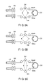
- FIG. 18 is a diagram schematically showing an example of a configuration of an endoscopic system according to a fifth embodiment of the present invention.
- FIG. 19 is a flowchart for explaining an example of processing in a control unit of the endoscopic system according to the fifth embodiment of the present invention.
- FIG. 20 is a diagram showing an example of information stored in a memory unit of the endoscopic system according to the fifth embodiment of the present invention.
- FIG. 21 is a diagram schematically showing an example of a configuration of an endoscopic system according to an embodiment that is a combination of the second embodiment and the third embodiment of the present invention.
- FIG. 22 is a diagram schematically showing an example of a configuration of an endoscopic system according to an embodiment that is a combination of the second embodiment and the fourth embodiment of the present invention.
- FIG. 23 is a diagram schematically showing an example of a configuration of an endoscopic system according to an embodiment that is a combination of the second embodiment and the fifth embodiment of the present invention.
- FIG. 24 is a diagram schematically showing an example of a configuration of an endoscopic system according to an embodiment that is a combination of the third embodiment and the fourth embodiment of the present invention.
- FIG. 25 is a diagram schematically showing an example of a configuration of an endoscopic system according to an embodiment that is a combination of the third embodiment and the fifth embodiment of the present invention.
- An endoscopic system stores pieces of information concerning a bent state of an insertion section in response to respective operative procedures when the insertion section is inserted into a subject, for example, when the insertion section is bent into a J-like shape in a stomach or it approaches a gallbladder through the stomach in natural orifice transluminal endoscopic surgery (NOTES).
- NOTES natural orifice transluminal endoscopic surgery
- FIG. 1 shows an outline of an overall configuration of the endoscopic system according to this embodiment.
- This endoscopic system has an insertion section 100 that is inserted into a subject and has an elongated shape and an operating section 200 used by an operator to perform various kinds of operations of this endoscopic system outside the subject.
- the insertion section 100 comprises an elongated flexible tube section 120 having flexibility and a bending section 140 coupled with a distal end of the flexible tube section 120 .
- the flexible tube section 120 includes a metallic helical tube, a reticular tube provided on an outer peripheral side of the helical tube, and a resin envelope that covers an outer peripheral surface of the reticular tube.
- the bending section 140 has a bending tube that is formed by aligning cylindrical node rings in the longitudinal direction of the bending section 140 and coupling the node rings through joints capable of swinging, a reticular tube provided on the outer peripheral side of the bending tube, and a resin envelop that covers an outer peripheral surface of the reticular tube.
- each coil pipe 170 is disposed to penetrate the flexible tube section 120 and the bending section 140 in the longitudinal direction, and angle wires 180 are inserted in these coil pipes 170 .
- one end of each coil pipe 170 arranged in the insertion section 100 is fixed by a coil receiver.
- First and second angle wires 180 forming a pair connect an RL angle pulley 210 to one node ring in the bending section 140 .
- one end of the first angle wire 180 is wound around and fixed to the RL angle pulley 210 , and the other end is fixed to the node ring through one of the four coil pipes 170 .
- the second angel wire 180 is wound around and fixed to the RL angle pulley 210 in an opposite direction of the winding direction of the first angle wire 180 , and the other end of the same is inserted into the coil pipe 170 and fixed to the same node ring.
- each of third and fourth angle wires 180 forming the other pair has one end likewise wound around and fixed to an UD angle pulley 220 and the other end inserted into the coil pipe 170 and fixed to the node ring in the bending section 140 .
- the UD angle pulley 220 rotates, the angle wires 180 for the UD angle are pulled and loosened, and the bending section 140 bends in an up-down direction.
- the bending section 140 can bent in multiaxial directions by using more joints.
- RL angle wires 180 a the pair of angle wires used for bending the bending section 140 in the right-left direction
- UD angle wires 180 b the pair of angle wires used for bending the bending section 140 in the up-down direction
- An RL tensile force adjustment unit 230 and an UD tensile force adjustment unit 240 are arranged between coil receivers 190 and the RL angle pulley 210 and between the coil receivers 190 and the UD angle pulley 220 , respectively.
- the RL tensile force adjustment unit 230 has a linear actuator 232 , a movable pulley 234 , and a movable pulley 236 .
- the UD tensile force adjustment unit 240 has a linear actuator 242 , a movable pulley 244 , and a movable pulley 246 to change tensile force of the UD angle wire 180 b.
- the operating section 200 has a control unit 250 , a memory unit 260 , and an input unit 270 .
- the input unit 270 is a unit that accepts instructions from an operator.
- the input unit 270 outputs instructions received from the operator to the control unit 250 .
- the memory unit 260 stores information required for arithmetic operations performed by the control unit 250 and outputs required information to the control unit 250 in response to a request from the control unit 250 .
- the control unit 250 reads out required information from the memory unit 260 based on an instruction from the operator input from the input unit 270 and executes an arithmetic operation by using this required information to calculate a value concerning adjustment of the angle wires 180 .
- the control unit 250 controls operations of the linear actuator 232 and the linear actuator 242 based on the calculated adjustment value.
- the bending section 140 functions as, e.g., a bending section provided in the elongated flexible insertion section
- the angle wires 180 function as, e.g., wires that are pulled or loosened to bend the bending section
- the memory unit 260 functions as, e.g., a memory unit that stores information indicative of a relationship between a shape of the insertion section and an adjustment value for driving an adjustment unit in case of this shape of the insertion section
- the RL tensile force adjustment unit 230 and the UD tensile force adjustment unit 240 function as, e.g., adjustment units that adjust tensile force applied to the wires
- the control unit 250 functions as, e.g., a control unit that determines an adjustment value and controls the adjustment units based on the adjustment value
- the input unit 270 functions as, e.g., an input unit that acquires a procedure mode in accordance with a procedure using the endoscopic system.
- the flexible tube section 120 may be bent with a relatively small curvature in such a manner that the flexible tube section 120 is bent into a J-like shape in, e.g., a digestive tract such as a stomach.
- a loop shape indicated by a solid line in FIG. 2B in the natural orifice transluminal endoscopic surgery (NOTES), it is also possible to consider a situation that the flexible tube section 120 is bent with a relatively large curvature to approach a gallbladder through the stomach. Besides, approaching a non-illustrated sigmoid colon, a descending colon, a transverse colon, an ascending colon, and others can be also considered.
- the adjustment of the angle wires 180 having the above-described configuration is carried out as follows. That is, when approaching the gallbladder via the stomach in NOTES, the flexible tube section 120 is inserted through a similar path every time the surgical operation is conducted. When the same procedure is performed in this manner, how the flexible tube section 120 is bent is substantially the same every time the surgical operation is conducted.
- this embodiment utilizes characteristics that how the flexible tube section 120 is bent is always substantially the same in every surgical operation. That is, a mode is previously set in accordance with an operative procedure or a target, and an adjustment value concerning the adjustment for the tensile force applied to the angle wires 180 based on how the flexible tube section 120 is bent is previously stored in accordance with each mode. Moreover, in this endoscopic system, the stored adjustment value is used to adjust the tensile force of the angle wires 180 .
- a situation where a curvature of bending of the flexible tube section 120 shown in FIG. 2A is relatively small is called a reversal (small) mode
- a situation where a curvature of bending of the flexible tube section 120 is relatively large like NOTES shown in FIG. 2B is called a reversal (large) mode
- a situation of approaching a sigmoid colon, a descending colon, a transverse colon, an ascending colon, and others is called a large intestine mode, respectively, and these modes are generically called a procedure mode.
- An operator first selects a desired procedure mode in accordance with a procedure that is being carried out and inputs the selected mode to the input unit 270 .
- the input unit 270 it is possible to apply an input device having a configuration that buttons for specifying the reversal (small) mode, the reversal (large) mode, and the large intestine mode, respectively are provided. It is also possible to adopt a configuration that the input unit 270 is formed of a keyboard or a mouse and additionally includes a non-illustrated display and others.
- the control unit 250 receives an indication of the procedure mode used by the operator from the input unit 270 .
- the control unit 250 reads an adjustment value concerning the corresponding procedure mode in adjustment values concerning adjustment of tensile force of the angle wires stored in the memory unit 260 in accordance with the procedure mode input from the input unit 270 .
- the memory unit 260 for example, as shown in FIG. 5 , a table concerned with the respective modes is provided, and the adjustment values concerning the adjustment of the tensile force of the angle wires 180 are stored in advance.
- a correspondent relationship of, e.g., increase/decrease levels of the tensile force for the angle wires 180 or adjustment levels of the RL tensile force adjustment unit 230 and the UD tensile force adjustment unit 240 with respect to each reference value are stored.
- the control unit 250 appropriately reads out an adjustment value in accordance with the procedure mode from these values and executes the adjustment.
- the control unit 250 calculates a drive amount of the linear actuator 232 for moving the movable pulley 234 and the movable pulley 236 of the RL tensile force adjustment unit 230 and a drive amount of the linear actuator 242 for moving the movable pulley 244 and the movable pulley 246 of the UD tensile force adjustment unit 240 in accordance with the read wire tensile force adjustment value.
- control unit 250 controls drive of the linear actuator 232 and the linear actuator 242 based on the calculated drive amounts, thereby adjusting the tensile force of the angle wires 180 .
- the RL tensile force adjustment unit 230 will be taken as an example to describe operations of the RL tensile force adjustment unit 230 and the UD tensile force adjustment unit 240 .
- the movable pulley 234 and the movable pulley 236 are moved by the linear actuator 232 .
- center positions of movable ranges of the movable pulley 234 and the movable pulley 236 are determined as a reference state.
- the movable pulley 234 and the movable pulley 236 are moved to shorten paths of the angle wires 180 as shown in FIG. 6B .
- the movable pulley 234 and the movable pulley 236 are moved to extend the paths of the angle wires 180 as shown in FIG. 6C .
- the tensile force applied to the angle wires 180 is adjusted in accordance with positions of the movable pulley 234 and the movable pulley 236 .
- the linear actuators may be provided to the movable pulley 234 and the movable pulley 236 , respectively so that these pulleys can be individually moved.
- tensile force adjustment can be carried out with respect to each of the two RL angle wires 180 a connected to one node ring. This configuration can be also applied to the UD tensile force adjustment unit 240 .
- Mechanisms of the RL tensile force adjustment unit 230 and the UD tensile force adjustment unit 240 are not restricted to configurations depicted in FIGS. 6A , 6 B, and 6 C, and any other configuration may be adopted if the tensile force of the angle wires 180 can be changed.
- a non-illustrated movement mechanism that moves a shaft of the RL angle pulley 210 may be provided to effect movement so that a distance between the RL angle pulley 210 and each coil receiver 190 can be changed.
- adjustment screws 238 that change an entire length may be provided between the RL angle pulley 210 and the coil receivers 190 so that the adjustment screws can be utilized to adjust the tensile force of the RL angle wires 180 a . That is, a screw adjustment mechanism 239 may rotate the adjustment screws 238 in accordance with a change in tensile force applied to the RL angle wires 180 a to change the entire length, thereby adjusting the tensile force of the RL angle wires 180 a.
- the tensile force of the angle wires 180 can be adjusted in accordance with each procedure mode in accordance with an operative procedure or a target to eliminate a change in tensile force caused due to a bent shape of the insertion section.
- the operator can constantly perform the bending operation for the bending section 140 with the same operational feeling irrespective of the bent shape of the flexible tube section 120 .
- the bending section 140 can have an expected bending angle (a bending amount) by an operation of the operator with the same operation feeling, this tensile force adjustment can exhibit the effect of realizing the more accurate operation of the bending section 140 without an uncomfortable feeling.
- the RL angle pulley 210 and the UD angle pulley 220 according to this embodiment have been described as manual operation mechanisms that rotate when the operator rotates the operation knobs coupled with these pulleys.
- the present invention is not restricted to this configuration, and the wire tensile force adjustment mechanism according to this embodiment can be likewise used in, e.g., an endoscopic system having an electric operation mechanism that electrically rotates the RL angle pulley 210 and the UD angle pulley 220 .
- the electric operation mechanism is used, likewise, to accurately operate the bending section 140 to bend, when the tensile force applied to the angle wires 180 is changed, a control parameter concerning the operation of the electric operation mechanism have to be adjusted in accordance with this change.
- the endoscopic system having the wire tensile force adjustment mechanism of this embodiment since the tensile force of the angle wires 180 is adjusted for each procedure mode in accordance with an operative procedure or a target to eliminate a change in tensile force caused due to a bent shape of the insertion section, the control parameter concerning the electric operation mechanism does not have to be adjusted in accordance with the tensile force of the angle wires 180 . Therefore, the tensile force adjustment of the angle wires 180 according to this embodiment exhibits the effect of facilitating the control of the electric operation mechanism.
- the wire tensile force adjustment mechanism is not restricted to use in an endoscope, and it can be likewise used in a flexible elongated manipulator that bends the bending section by pulling or loosening the wires, thereby obtaining the same effect.
- An endoscopic system according to this embodiment is exemplified by a multistage bending endoscope that comprises joints including a first bending section 142 placed on a distal end side of an insertion section 100 and a second bending section 144 placed on a proximal end side of the first bending section 142 .
- angle wires 180 configured to bend the first bending section 142 run through the second bending section 144 , their tensile force varies depending on a bent shape such as a bending angle or a bending direction of the second bending section 144 . Therefore, in this embodiment, tensile force of first angle wires 382 configured to drive the first bending section 142 is adjusted in accordance with the bent shape of the second bending section 144 arranged on the proximal end side.
- the bent shape of the second bending section 144 is acquired by detecting a moving distance of the second angle wires 384 configured to bend the second bending section 144 .
- each of the pair of first angle wires 382 configured to bend the first bending, section 142 is wound around and fixed to a first bending pulley 310 in an operating section 200 like the first embodiment. Furthermore, the other end of each of the pair of first angle wires 382 is inserted into the insertion section 100 and fixed to a node ring of the first bending section 142 . Likewise, one end of each of the pair of second angle wires 384 configured to bend the second bending section 144 is wound around and fixed to the second bending pulley 320 , and the other end of the same is inserted into the insertion section 100 and fixed to a node ring of the second bending section 144 .
- the same tensile force adjustment unit 330 as the RL tensile force adjustment unit 230 according to the first embodiment is arranged between coil receivers 190 and the first bending pulley 310 .
- the tensile force adjustment unit 330 is connected to the control unit 250 like the first embodiment to adjust the tensile force of the first angle wires 382 under control of the control unit 250 .
- a wire pulling distance detection unit 350 that detects a moving distance of the second angle wires 384 is arranged between the coil receivers 190 and the second bending pulley 320 .
- the wire pulling distance detection unit 350 is, e.g., a linear encoder that detects a moving distance of the second angle wires 384 .
- the wire pulling distance detection unit 350 may be a potentiometer that detects a rotational angle of the second bending pulley 320 that pulls and loosens the second angle wires 384 .
- the wire pulling distance detection unit 350 outputs the detected moving distance of the second angle wires 384 to the control unit 250 .
- the control unit 250 reads necessary information from a memory unit 260 based on the moving distance of the second angle wires 384 input from the wire pulling distance detection unit 350 and calculates a value concerning adjustment of the tensile force of the first angle wires 382 .
- the control unit 250 controls an operation of the tensile force adjustment unit 330 based on the calculated adjustment value.
- the wire pulling distance detection unit 350 functions as a wire moving distance detection unit that detects a moving distance of the wires that transmit power to at least one of the bending sections.
- the control unit 250 acquires a moving distance of the second angle wires 384 from the wire pulling distance detection unit 350 .
- the control unit 250 reads a necessary adjustment value in adjustment values concerning adjustment for tensile force of the first angle wires 382 stored in the memory unit 260 in accordance with the acquired moving distance of the second angle wires 384 .
- the memory unit 260 stores the adjustment values in connection with moving distances of the second angle wires 384 .
- a function representing such a relationship may be saved.
- the control unit 250 calculates a drive amount of a mechanism in the tensile force adjustment unit 330 in accordance with the read adjustment value. For example, like the RL tensile force adjustment unit 230 in the first embodiment, when a mechanism including a movable pulley is provided, a drive amount of a linear actuator for moving this movable pulley is calculated.
- control unit 250 controls drive of the mechanism in the tensile force adjustment unit 330 based on the calculated drive amount, thereby adjusting the tensile force of the first angle wires 382 .
- a bent state of the second bending section 144 that changes the tensile force of the first angle wires 382 is detected by acquiring the moving distance of the second angle wires 384 .
- the change in tensile force caused due to the bent shape of the second bending section 144 can be eliminated.
- an operator can always operate the first bending section 142 to bend with the same operational feeling irrespective of the bent shape of the second bending section 144 .
- the first bending section 142 can have an expected bending angle (a bending amount) by the operation of the operator with the same operational feeling, this tensile force adjustment exhibits the effect of realizing the more accurate operation of the first bending section 142 without an uncomfortable feeling.
- an input unit 270 may be provided so that the tensile force of each of the first angle wires 382 and the second angle wires 384 can be adjusted on the basis of a bent state of a flexible tube section 120 determined for each procedure mode in accordance with an operative procedure or a target like the first embodiment.
- the tensile force adjustment of the first angle wires 382 like the first embodiment, the tensile force adjustment is carried out for each procedure mode with reference to, e.g., such information as depicted in FIG. 5 , and then the tensile force adjustment based on a moving distance of the second angle wires 384 according to this embodiment is performed.
- an adjustment value concerning the adjustment for the tensile force of the first angle wires 382 is a sum of an adjustment value based on the procedure mode and an adjustment value based on the moving distance of the second angle wires 384 .
- the input unit 270 and the wire pulling distance detection unit 350 function as a shape acquiring unit.
- a first bending pulley 310 and a second bending pulley 320 may be, e.g., electric operation mechanisms rotated by electric power. Even in this case, since the tensile force of the first angle wires 382 (including the second angle wires 384 when performing the tensile force adjustment according to a procedure mode) is adjusted, a control parameter concerning the electric operation mechanism does not have to be adjusted in accordance with the tensile force of the first angle wires 382 (and the second angle wires 384 ). Therefore, the tensile force adjustment according to this embodiment exhibits the effect of facilitating control of the electric operation mechanism.
- each of the first bending section 142 and the second bending section 144 is not restricted to a configuration including one bending pulley like this embodiment, and it may have a configuration including two bending pulleys to enable bending in four directions, i.e., up, down, left, and right directions.
- the bending sections are not restricted to the two bending sections, i.e., the first bending section 142 and the second bending section 144 , and three or more bending sections may be provided.
- the bending section on the distal end side can be configured in such a manner that tensile force of the driving angle wires can be adjusted on the basis of bent states of the bending sections provided on the proximal end side of this bending section.
- this endoscopic system has the same effect as that of this embodiment.
- the tensile force adjustment mechanism for the wires is not restricted to the endoscope, and it can be likewise used in a flexible elongated manipulator that bends the bending sections by pulling and loosening the wires like the endoscope, thereby obtaining the same effect.
- the endoscopic system is an endoscopic system having a configuration that a manipulator is inserted in a forceps opening of an insertion section 100 of an endoscope.
- Basic mechanisms of the manipulator are equal to the structures in the endoscope except that an insertion section 490 has a small diameter in order to be inserted into the forceps opening of the endoscope.
- a bending section 494 is provided at a distal end of the insertion section 490 of the manipulator. This bending section 494 is bent by pulling and loosening RL angle wires 480 a by an RL angle pulley 410 and pulling and loosening UD angle wires 480 b by a UD angle pulley 420 .
- Tensile force of the RL angle wires 480 a and that of the UD angle wires 480 b vary depending on a bent shape of a bending section 140 of the endoscope in which these wires are inserted.
- the tensile force of the RL angle wires 480 a and that of the UD angle wires 480 b are adjusted in accordance with a bent shape of the bending section 140 of the endoscope to improve an operational feeling of the bending section 494 of the manipulator for an operator.
- the insertion section 490 of the manipulator comprises an elongated flexible tube section 492 and the bending section 494 provided at a distal end of this flexible tube section 492 . Furthermore, like the endoscope, the pair of RL angle wires 480 a configured to drive the bending section 494 in a right-left direction and the pair of UD angle wires 480 b configured to drive the bending section 494 in an up-down direction are inserted into the insertion section 490 .
- each of the pair of RL angle wires 480 a is wound around and fixed to the RL angle pulley 410 in an operating section 400 of the manipulator. Moreover, the other end of each of the pair of RL angle wires 480 a is fixed to a node ring of the bending section 494 . Likewise, one end of each of the pair of UD angle wires 480 b is wound around and fixed to the UD angle pulley 420 in the operating section 400 of the manipulator, and the other end of the same is fixed to a node ring of the bending section 494 .
- the same RL tensile force adjustment unit 430 as the RL tensile force adjustment unit 230 according to the first embodiment is provided to the RL angle wires 480 a
- the same UD tensile force adjustment unit 440 is provided to the UD angle wires 480 b .
- the RL tensile force adjustment unit 430 and the UD tensile force adjustment unit 440 are connected to a control unit 470 of the manipulator.
- the RL tensile force adjustment unit 430 and the UD tensile force adjustment unit 440 drive to adjust tensile force of the RL angle wires 480 a and that of the UD angle wires 480 b under control of the control unit 470 , respectively.
- the same RL wire pulling distance detection unit 450 as the wire pulling distance detection unit 350 in the second embodiment is provided to the RL angle wires 180 a configured to bend the bending section 140 of the endoscope.
- a UD wire pulling distance detection unit 460 is provided to the UD angle wires 180 b .
- the RL wire pulling distance detection unit 450 and the UD wire pulling distance detection unit 460 are connected to the control unit 470 to output moving distances of the RL angle wires 180 a and the UD angle wires 180 b to the control unit 470 , respectively.
- the control unit 470 calculates a value concerning adjustment of tensile force of each of the RL angle wires 480 a and the UD angle wires 480 b based on inputs from the RL wire pulling distance detection unit 450 and the UD wire pulling distance detection unit 460 by utilizing information stored in a memory unit 475 .
- the control unit 470 also controls the RL tensile force adjustment unit 430 and the UD tensile force adjustment unit 440 to adjust the tensile force of each of the RL angle wires 480 a and the UD angle wires 480 b.
- the insertion section 100 functions as, e.g., a flexible elongated endoscope insertion section
- the bending section 140 functions as, e.g., an endoscope bending section
- the RL angle wires 180 a and the UD angle wires 180 b function as, e.g., endoscope wires configured to bend the endoscope bending section
- the RL wire pulling distance detection unit 450 and the UD wire pulling distance detection unit 460 function as, e.g., manipulator shape acquiring units
- the insertion section 490 functions as, e.g., a manipulator
- the RL angle wires 480 a and the UD angle wires 480 b function as, e.g., manipulator wires configured to transmit power for bending the manipulator bending section
- the RL tensile force adjustment unit 430 and the UD tensile force adjustment unit 440 function as, e.g., manipulator adjustment units configured to adjust tensile force applied to the
- the control unit 470 acquires moving distances of the RL angle wires 180 a and the UD angle wires 180 b of the endoscope from the RL wire pulling distance detection unit 450 and the UD wire pulling distance detection unit 460 .
- the control unit 470 reads necessary adjustment values in adjustment values concerning adjustment of tensile force of each of the RL angle wires 480 a and the UD angle wires 480 b stored in the memory unit 475 in accordance with the acquired moving distances of the RL angle wires 180 a and the UD angle wires 180 b .
- the memory unit 475 stores the adjustment values concerning the adjustment of the tensile force of each of the RL angle wires 480 a and the UD angle wires 480 b of the manipulator in connection with the moving distances of the RL angle wires 180 a and the UD angle wires 180 b of the endoscope.
- FIG. 14 stores the adjustment values concerning the adjustment of the tensile force of each of the RL angle wires 480 a and the UD angle wires 480 b of the manipulator in connection with the moving distances of the RL angle wires 180 a and the UD angle wires 180 b of the endoscope.
- an upper side in each column represents an adjustment value concerning the adjustment of the tensile force of the RL angle wires 480 a
- a lower side in the same presents an adjustment value concerning the adjustment of the tensile force of the UD angle wires 180 b
- a function representing such relationships may be saved.
- control unit 470 calculates drive amounts of mechanisms in the RL tensile force adjustment unit 430 and the UD tensile force adjustment unit 440 in accordance with the read adjustment values.
- the control unit 470 controls drive of the mechanisms in the RL tensile force adjustment unit 430 and the UD tensile force adjustment unit 440 of the manipulator based on the calculated drive amounts, thereby adjusting the tensile force of each of the RL angle wires 480 a and the UD angle wires 480 b of the manipulator.
- a bent shape of the bending section 140 that can be a cause of a change in the tensile force of each of the RL angle wires 480 a and the UD angle wires 480 b of the manipulator is acquired by detecting moving distances of the RL angle wires 180 a and the UD angle wires 180 b of the endoscope, and the tensile force of each of the RL angle wires 480 a and the UD angle wires 480 b of the manipulator can be adjusted in accordance with the acquired bent shape of the bending section 140 of the endoscope.
- an operator can constantly bend the bending section 494 of the manipulator with the same operational feeling irrespective of a bent shape of the bending section 140 of the endoscope without regard to this shape. Since the bending section 494 of the manipulator can have an expected bending angle by an operation of the operator with the same operational feeling, this tensile force adjustment can exhibit the effect of realizing the more accurate operation of the bending section 494 without an uncomfortable feeling.
- the input unit 270 may be provided like the first embodiment so that tensile force of each of the RL angle wires 480 a and the UD angle wires 480 b of the manipulator can be adjusted on the basis of a bent state of the flexible tube section 120 in each procedure mode in accordance with an operative procedure or a target.
- the tensile force adjustment based on a procedure mode is carried out, and then the tensile force adjustment based on moving distances of the RL angle wires 180 a and the UD angle wires 180 b of the endoscope according to this embodiment is performed.
- the adjustment value concerning the tensile force adjustment of the RL angle wires 480 a and the UD angle wires 480 b is a sum of an adjustment value based on the procedure mode and an adjustment value based on moving distances of the RL angle wires 180 a and the UD angle wires 180 b of the endoscope.
- the input unit 270 , the RL wire pulling distance detection unit 450 , and the UD wire pulling distance detection unit 460 function as a shape acquiring unit. Even in this case, the endoscopic system exhibits the same effect as that of this embodiment.
- the RL angle pulley 410 and the UD angle pulley 420 may be, e.g., electric operation mechanisms that are rotated by electric power.
- the tensile force of each of the RL angle wires 480 a and the UD angle wires 480 b is adjusted, a control parameter concerning the electric operation mechanisms in accordance with the tensile force of the RL angle wires 480 a and the UD angle wires 480 b does not have to be adjusted. Therefore, the tensile force adjustment according to this embodiment exhibits the effect of facilitating the control of the electric operation mechanisms.
- a fourth embodiment according to the present invention will now be described.
- a difference from the first embodiment will be described, and like reference numbers denote parts equal to those in the first embodiment, thereby omitting a description thereof.
- An endoscopic system according to this embodiment is combined with a system that can acquire a shape of an endoscope.
- an endoscope insertion shape observation apparatus an endoscope position detection unit; UPD
- a flexible tube section 120 includes magnetic coils 555 .
- the UPD 550 receives magnetism generated from the magnetic coils 555 by a non-illustrated antenna provided in the UPD 550 to calculate a shape of the flexible tube section 120 .
- the UPD 550 outputs the calculated shape of the flexible tube section 120 of an endoscope to a control unit 250 of the endoscope. It is to be noted that the UPD is disclosed in, e.g., Jpn. Pat. Appln. KOKAI Publication No. 2000-79087.
- the present invention is not restricted to the UPD 550 , and this unit may be substituted by an apparatus that utilizes, e.g., an X-ray apparatus to acquire a shape of the flexible tube section 120 .
- the control unit 250 of the endoscope reads information concerning tensile force adjustment of angle wires 180 from a memory unit 260 based on the shape of the flexible tube section 120 input from the UPD 550 , uses this information to perform arithmetic processing, and thereby controls operations of an RL tensile force adjustment unit 230 and a UD tensile force adjustment unit 240 .
- each magnetic coil 555 functions as, e.g., an indicator arranged in an insertion section
- the UPD 550 functions as, e.g., an insertion shape observation apparatus that acquires a shape of the insertion section in a contactless manner.
- the control unit 250 acquires information concerning a shape of the flexible tube section 120 from the UPD 550 .
- control unit 250 calculates a bending direction, a curvature, and others of each portion of the flexible tube section from the acquired information concerning the shape of the flexible tube section 120 .
- the control unit 250 reads necessary adjustment values in adjustment values concerning tensile force adjustment of wires stored in the memory unit 260 in accordance with the bending directions, the curvatures, and others of the flexible tube section 120 .
- the memory unit 260 stores values concerning the adjustment of the tensile force of each of the RL angle wires 180 a and the UD angle wires 180 b in connection with bending amounts of the flexible tube section 120 in an RL direction and a UD direction.
- FIG. 17 the memory unit 260 stores values concerning the adjustment of the tensile force of each of the RL angle wires 180 a and the UD angle wires 180 b in connection with bending amounts of the flexible tube section 120 in an RL direction and a UD direction.
- an upper side in each column represents an adjustment value concerning the adjustment of the tensile force of the RL angle wires 180 a
- a lower side in the same presents an adjustment value concerning the adjustment of the tensile force of the UD angle wires 180 b .
- a function representing such relationships may be saved.
- control unit 250 calculates drive amounts of mechanisms in the RL tensile force adjustment unit 230 and the UD tensile force adjustment unit 240 in accordance with the read adjustment values.
- control unit 250 controls drive of the mechanisms in the RL tensile force adjustment unit 23 and the UD tensile force adjustment unit 240 based on the calculated drive amount, and adjusts tensile force of each of the RL angle wires 180 a and the UD angle wires 180 b.
- a shape of the flexible tube section 120 that changes the tensile force of each of the RL angle wires 180 a and the UD angle wires 180 b of the endoscope is acquired by using each magnetic coil 555 and the UPD 550 , and the tensile force of each of the RL angle wires 180 a and the UD angle wires 180 b can be adjusted in accordance with the shape of the flexible tube section 120 .
- an operator can constantly bend the bending section 140 with the same operational feeling irrespective of a bent shape of the flexible tube section 120 of the endoscope without regard to this shape. Since the bending section 140 can have an expected bending angle (an bending amount) by an operation of the operator with the same operational feeling, this tensile adjustment can exhibit the effect of realizing the more accurate operation of the bending section 140 without an uncomfortable feeling.
- each of the RL angle pulley 210 and the UD angle pulley 220 may be, e.g., an electric operation mechanism that is rotated by electric power. Even in this case, since tensile force of each of the RL angle wires 180 a and the UD angle wires 180 b is adjusted, a control parameter concerning the electric operation mechanism in accordance with the tensile force of each of the RL angle wires 180 a and the UD angle wires 180 b does not have to be adjusted. Therefore, the tensile force adjustment according to this embodiment can exhibit the effect of facilitating control of the electric operation mechanism.
- the tensile force adjustment mechanism for the wires is not restricted to the endoscope, and it can be likewise used in a manipulator that has a flexible elongated shape and bends the bending section by pulling and loosening the wires, thereby obtaining the same effect.
- a fifth embodiment according to the present invention will now be described.
- An endoscopic system according to this embodiment is combined with an endoscope comprising an overtube configured to bend a flexible tube section 120 of the endoscope by an operation of an operator.
- an overtube 660 is provided on a circumferential portion of the flexible tube section 120 .
- coil pipes 670 are inserted in the overtube 660 , and the coil pipes 670 are extended to an operating section 200 and fixed to the operating section 200 by coil receivers 690 .
- Overtube wires 680 are inserted in the coil pipes 670 .
- the overtube wires 680 are wound around and fixed to an overtube pulley 610 in the operating section 200 . Therefore, when the operator rotates a non-illustrated angle knob connected to the overtube pulley 610 , the overtube pulley 610 rotates to pull and loosen the overtube wires 680 . As a result, the flexible tube section 120 of the endoscope in the overtube 660 is bent.
- the same wire pulling distance detection unit 650 as the wire pulling distance detection unit 350 according to the second embodiment is arranged between the coil receiver 690 and the overtube pulley 610 to acquire a moving distance of the overtube wires 680 .
- this wire pulling distance detection unit 650 may be, e.g., a linear encoder that detects a moving distance of the overtube wires 680 or a potentiometer that detects a rotational angle of the overtube pulley 610 as described in the second embodiment.
- the wire pulling distance detection unit 650 outputs the detected moving distance of the overtube wires 680 to a control unit 250 .
- the control unit 250 reads an adjustment value concerning tensile force adjustment of RL angle wires 180 a and UD angle wires 180 b based on the moving distance of the overtube wires 680 input from the wire pulling distance detection unit 650 and executes arithmetic processing by using the read adjustment value to control operations of the RL tensile force adjustment unit 230 and the UD tensile force adjustment unit 240 .
- the overtube 660 functions as, e.g., an overtube that covers the circumferential surface of the insertion section and bends the insertion section
- the overtube wires 680 function as, e.g., tube wires that transmit power to the overtube
- the wire pulling distance detection unit 650 functions as, e.g., a tube wire moving distance detection unit that detects a moving distance of the tube wires as a shape acquiring unit.
- the control unit 250 acquires a moving distance of the overtube wires 680 from the wire pulling distance detection unit 650 .
- the control unit 250 reads a necessary adjustment value in adjustment values concerning tensile force adjustment of the wires stored in a memory unit 260 in accordance with the acquired moving distance of the overtube wires 680 .
- the overtube wire 680 has wires for bending in an RL direction and wires for bending in a UD direction and the wire pulling distance detection unit 650 acquires respective amounts of displacement, for example, as shown in FIG. 20
- the memory unit 260 stores adjustment values concerning tensile force adjustment of the RL angle wires 180 a and the UD angle wires 180 b in connection with moving distances of the overtube wires 680 . For example, as shown in FIG.
- the control unit 250 calculates a drive amount of a mechanism in the tensile force adjustment unit 330 in accordance with a read adjustment value. For example, when the same mechanism as the RL tensile force adjustment unit 230 in the first embodiment is provided, a drive amount of the linear actuator 232 for moving the movable pulley 234 is calculated.
- control unit 250 controls drive of mechanisms in the RL tensile force adjustment unit 230 and the UD tensile force adjustment unit 240 based on the calculated drive amount, thereby adjusting the tensile force of the angle wires 180 .
- a bent shape of the flexible tube section 120 that changes the tensile force of the angle wires 180 is detected by acquiring a moving distance of the overtube wires 680 , and the tensile force of the angle wires 180 can be adjusted on the basis of the detected bent state of the flexible tube section 120 .
- an operator can always naturally operate the bending section 140 to bend with the same operational feeling irrespective of the bent state of the flexible tube section 120 .
- the bending section 140 can have an expected bending angle (a bending amount) by the operation of the operator with the same operational feeling, this tensile force adjustment exhibits the effect of realizing the more accurate operation of the bending section 140 without an uncomfortable feeling.
- each of the RL angle pulley 210 and the UD angle pulley 220 may be, e.g., an electric operation mechanism rotated by electric power.
- the tensile force adjustment according to this embodiment exhibits the effect of facilitating control of the electric operation mechanism.
- the tensile force adjustment mechanism of the wires is not restricted to the endoscope, and it can be likewise used in a manipulator that has a flexible elongated shape and bends the bending section by pulling and loosening the wires, thereby obtaining the same effect.
- first wire pulling distance detection unit 352 and a second wire pulling distance detection unit 354 detect moving distances of first angle wires 382 and second angle wires 384 configured to bend a first bending section 142 and a second bending section 144 , respectively.
- the first wire pulling distance detection unit 352 and the second wire pulling distance detection unit 354 output the detected moving distances of the first angle wires 382 and the second angle wires 384 to a control unit 470 of a manipulator.
- the control unit 470 calculates a value concerning tensile force adjustment of RL angle wires 480 a and UD angle wires 480 b of the manipulator while making reference to information stored in a memory unit 475 . Further, an RL tensile force adjustment unit 430 and a UD tensile force adjustment unit 440 are controlled to adjust tensile force of each of the RL angle wires 480 a and the UD angle wires 480 b .
- the first wire pulling distance detection unit 352 and the second wire pulling distance detection unit 354 function as wire moving distance detection units which are manipulator shape acquiring unit.
- a flexible tube section 120 of an endoscope includes magnetic coils 555
- a UPD 550 detects magnetism from the magnetic coils 555 and outputs information concerning a shape of the flexible tube section 120 to a control unit 250 .
- a wire pulling distance detection unit 350 detects a moving distance of second angle wires 384 and outputs this moving distance to the control unit 250 .
- the control unit 250 calculates a value concerning adjustment of tensile force applied to first angle wires 382 from a shape of the flexible tube section 120 input from the UPD 550 and a moving distance of the second angle wires 384 input from the wire pulling distance detection unit 350 while making reference to information stored in a memory unit 260 .
- the tensile force adjustment is carried out based on the shape of the flexible tube section 120 with reference to such information as depicted in FIG. 17 , and then the tensile force adjustment is performed based on the moving distance of the second angle wires 384 according to the second embodiment.
- the adjustment value concerning the tensile force adjustment of the first angle wires 382 is a sum of an adjustment value based on an input from the UPD 550 and an adjustment value based on a moving distance of the second angle wires 384 .
- the control unit 250 controls a tensile force adjustment unit 330 to adjust the tensile force of the first angle wires 382 .
- the UPD 550 functions as, e.g., an insertion shape observation apparatus which is a manipulator shape acquiring unit
- the wire pulling distance detection unit 350 functions as, e.g., a wire moving distance detection unit.
- a flexible tube section 120 of an endoscope has an overtube 660 , and overtube wires 680 configured to bend the overtube 660 and a wire pulling distance detection unit 650 configured to detect tensile force of the wires are provided.
- the wire pulling distance detection unit 650 outputs a moving distance of the overtube wires 680 concerning a shape of a flexible tube section 120 to a control unit 250 like the fifth embodiment.
- the wire pulling distance detection unit 350 detects a moving distance of second angle wires 384 and outputs the moving distance to the control unit 250 .
- the control unit 250 calculates a value concerning adjustment of tensile force applied to first angle wires 382 from the moving distance of the overtube wires 680 input from the wire pulling distance detection unit 650 and the moving distance of the second angle wires 384 input from the wire pulling distance detection unit 350 while making reference to information stored in a memory unit 260 .
- tensile force adjustment of the first angle wires 382 for example, tensile force adjustment is performed based on an input from the wire pulling distance detection unit 650 with reference to such information as shown in FIG. 20 , and then the tensile force adjustment based on the moving distance of the second angle wires 384 according to the second embodiment is effected.
- the adjustment value concerning adjustment of the tensile force applied to the first angle wires 382 is a sum of an adjustment value based on an input from the wire pulling distance detection unit 650 and an adjustment value based on the moving distance of the second angle wires 384 .
- the control unit 250 controls a tensile force adjustment unit 330 to adjust the tensile force of the first angle wires 382 .
- the wire pulling distance detection unit 650 and the wire pulling distance detection unit 350 function as a tube wire moving distance detection unit and a wire moving distance detection unit, respectively, which are manipulator shape acquiring units.
- a flexible tube section 120 of an endoscope includes magnetic coils 555
- a UPD 550 detects magnetism from the magnetic coils 555 and outputs information concerning a shape of the flexible tube section 120 to a control unit 470 of a manipulator.
- the control unit 470 calculates a value concerning adjustment of tensile force of each of RL angle wires 480 a and UD angle wires 480 b like the third embodiment based on the shape of the flexible tube section 120 with reference to such information stored in a memory unit 475 as depicted in FIG. 17 like the fourth embodiment.
- the control unit 470 controls an RL tensile force adjustment unit 430 and a UD tensile force adjustment unit 440 to adjust the tensile force of each of the RL angle wires 480 a and the UD angle wires 480 b .
- the UPD 550 functions as an insertion shape observation apparatus which is a manipulator shape acquiring unit.
- a flexible tube section 120 of an endoscope has an overtube 660 , and it also has overtube wires 680 configured to bend the overtube 660 and a wire pulling distance detection unit 650 configured to detect tensile force of the wires.
- the wire pulling distance detection unit 650 outputs a moving distance of the overtube wires 680 concerning a shape of the flexible tube section 120 to a control unit 470 of the manipulator.
- the control unit 470 calculates a value concerning adjustment of tensile force of each of RL angle wires 480 a and UD angle wires 480 b based on the input moving distance of the overtube wire 680 and an input from the wire pulling distance detection unit 650 with reference to such information stored in memory unit 475 as depicted in FIG. 20 like the fifth embodiment. Furthermore, an RL tensile force adjustment unit 430 and a UD tensile force adjustment unit 440 are controlled to adjust the tensile force of each of the RL angle wires 480 a and the UD angle wires 480 b .
- the wire pulling distance detection unit 650 functions as a tube wire moving distance detection unit which is a manipulator shape acquiring unit.
- a shape of a flexible tube section 120 of a multistage bending endoscope is acquired by a UPD 550 or a wire pulling distance detection unit 650 of an overtube 660 , and a control unit 470 of a manipulator calculates an adjustment value of tensile force of each of RL angle wires 480 a and UD angle wires 480 b in response to input of the acquired shape and controls an RL tensile force adjustment unit 430 and a UD tensile force adjustment unit 440 to adjust the tensile force of the RL angle wires 480 a and the UD angle wires 480 b.
- the tensile force adjustment in the endoscopic system exhibits the effect of realizing the more accurate operation of the bending section without an uncomfortable feeling like the first to fifth embodiments. Additionally, when the pulley is, e.g., the electric operation mechanism, the effect of facilitating the control of the electric operation mechanism can be obtained.
Abstract
Description
Claims (12)
Applications Claiming Priority (3)
| Application Number | Priority Date | Filing Date | Title |
|---|---|---|---|
| JP2010-061588 | 2010-03-17 | ||
| JP2010061588 | 2010-03-17 | ||
| PCT/JP2010/069311 WO2011114568A1 (en) | 2010-03-17 | 2010-10-29 | Endoscope system |
Related Parent Applications (1)
| Application Number | Title | Priority Date | Filing Date |
|---|---|---|---|
| PCT/JP2010/069311 Continuation WO2011114568A1 (en) | 2010-03-17 | 2010-10-29 | Endoscope system |
Publications (2)
| Publication Number | Publication Date |
|---|---|
| US20120046522A1 US20120046522A1 (en) | 2012-02-23 |
| US8915841B2 true US8915841B2 (en) | 2014-12-23 |
Family
ID=44648687
Family Applications (1)
| Application Number | Title | Priority Date | Filing Date |
|---|---|---|---|
| US13/213,844 Active 2030-12-13 US8915841B2 (en) | 2010-03-17 | 2011-08-19 | Endoscopic system |
Country Status (5)
| Country | Link |
|---|---|
| US (1) | US8915841B2 (en) |
| EP (1) | EP2517613B1 (en) |
| JP (1) | JP5048158B2 (en) |
| CN (1) | CN102770060B (en) |
| WO (1) | WO2011114568A1 (en) |
Cited By (7)
| Publication number | Priority date | Publication date | Assignee | Title |
|---|---|---|---|---|
| US20160360950A1 (en) * | 2014-02-28 | 2016-12-15 | Olympus Corporation | Medical instrument, medical system, and mode transition method for medical instruments |
| US20180256269A1 (en) * | 2013-05-02 | 2018-09-13 | Medrobotics Corporation | Robotic system including a cable interface assembly |
| US11007641B2 (en) | 2017-07-17 | 2021-05-18 | Canon U.S.A., Inc. | Continuum robot control methods and apparatus |
| US11278366B2 (en) | 2017-04-27 | 2022-03-22 | Canon U.S.A., Inc. | Method for controlling a flexible manipulator |
| US11504501B2 (en) | 2015-10-15 | 2022-11-22 | Canon U.S.A., Inc. | Steerable medical instrument |
| US11576563B2 (en) | 2016-11-28 | 2023-02-14 | Adaptivendo Llc | Endoscope with separable, disposable shaft |
| USD1018844S1 (en) | 2020-01-09 | 2024-03-19 | Adaptivendo Llc | Endoscope handle |
Families Citing this family (66)
| Publication number | Priority date | Publication date | Assignee | Title |
|---|---|---|---|---|
| EP3788944B1 (en) | 2005-11-22 | 2024-02-28 | Intuitive Surgical Operations, Inc. | System for determining the shape of a bendable instrument |
| US20130303944A1 (en) | 2012-05-14 | 2013-11-14 | Intuitive Surgical Operations, Inc. | Off-axis electromagnetic sensor |
| US9387048B2 (en) | 2011-10-14 | 2016-07-12 | Intuitive Surgical Operations, Inc. | Catheter sensor systems |
| US10238837B2 (en) | 2011-10-14 | 2019-03-26 | Intuitive Surgical Operations, Inc. | Catheters with control modes for interchangeable probes |
| US9452276B2 (en) | 2011-10-14 | 2016-09-27 | Intuitive Surgical Operations, Inc. | Catheter with removable vision probe |
| US20140148673A1 (en) | 2012-11-28 | 2014-05-29 | Hansen Medical, Inc. | Method of anchoring pullwire directly articulatable region in catheter |
| US10619714B2 (en) * | 2013-03-13 | 2020-04-14 | Boston Scientific Scimed, Inc. | Steerable medical device having a control member holding mechanism |
| CN103293593A (en) * | 2013-05-27 | 2013-09-11 | 上海大学 | Buckling and deforming optical fiber and application thereof in endoscopic catheter |
| JP6116426B2 (en) * | 2013-07-25 | 2017-04-19 | オリンパス株式会社 | Manipulator system |
| JP6116427B2 (en) * | 2013-07-26 | 2017-04-19 | オリンパス株式会社 | Manipulator and manipulator system |
| JP6157258B2 (en) | 2013-07-26 | 2017-07-05 | オリンパス株式会社 | Manipulator and manipulator system |
| JP6037964B2 (en) * | 2013-07-26 | 2016-12-07 | オリンパス株式会社 | Manipulator system |
| JP6027947B2 (en) * | 2013-07-26 | 2016-11-16 | オリンパス株式会社 | Manipulator system |
| US10550918B2 (en) | 2013-08-15 | 2020-02-04 | Intuitive Surgical Operations, Inc. | Lever actuated gimbal plate |
| KR102160753B1 (en) * | 2013-09-13 | 2020-09-28 | 삼성전자주식회사 | Endoscope device |
| US11051892B2 (en) | 2013-09-20 | 2021-07-06 | Canon U.S.A., Inc. | Control apparatus and tendon-driven device |
| GB2519993B (en) * | 2013-11-04 | 2017-05-10 | The Shadow Robot Company Ltd | Robotic hand |
| WO2015079809A1 (en) * | 2013-11-29 | 2015-06-04 | オリンパス株式会社 | Curve part of endoscope |
| JP6374672B2 (en) * | 2014-02-28 | 2018-08-15 | オリンパス株式会社 | Medical instruments and medical systems |
| CN106132345B (en) * | 2014-03-17 | 2019-05-31 | 直观外科手术操作公司 | System and method for keeping tool posture |
| EP2923669B1 (en) | 2014-03-24 | 2017-06-28 | Hansen Medical, Inc. | Systems and devices for catheter driving instinctiveness |
| JP6169049B2 (en) | 2014-06-19 | 2017-07-26 | オリンパス株式会社 | Manipulator control method, manipulator, and manipulator system |
| JP6265853B2 (en) * | 2014-07-10 | 2018-01-24 | オリンパス株式会社 | Medical equipment |
| EP3200718A4 (en) | 2014-09-30 | 2018-04-25 | Auris Surgical Robotics, Inc | Configurable robotic surgical system with virtual rail and flexible endoscope |
| JP5897092B2 (en) * | 2014-10-14 | 2016-03-30 | オリンパス株式会社 | Tubular insertion device |
| JP5797318B2 (en) * | 2014-10-14 | 2015-10-21 | オリンパス株式会社 | Tubular insertion device |
| US10314463B2 (en) | 2014-10-24 | 2019-06-11 | Auris Health, Inc. | Automated endoscope calibration |
| CN105559735A (en) * | 2014-11-05 | 2016-05-11 | 深圳市古安泰自动化技术有限公司 | Endoscope |
| CN107205622B (en) * | 2015-01-16 | 2019-09-20 | B-K医疗公司 | Ultrasound imaging probe |
| CN107073723A (en) * | 2015-02-25 | 2017-08-18 | 奥林巴斯株式会社 | Manipulator and arm-and-hand system |
| EP3692940B1 (en) * | 2015-05-15 | 2023-12-13 | Intuitive Surgical Operations, Inc. | A computer assisted medical device with torque limit compensation |
| EP3202303A4 (en) * | 2015-05-28 | 2018-10-31 | Olympus Corporation | Endoscope |
| JP6644816B2 (en) * | 2015-06-30 | 2020-02-12 | キヤノン ユーエスエイ,インコーポレイテッドCanon U.S.A.,Inc | Method and apparatus for controlling a manipulator |
| WO2017009905A1 (en) * | 2015-07-10 | 2017-01-19 | オリンパス株式会社 | Flexible tube insertion device |
| CN107848120B (en) * | 2015-07-17 | 2021-01-08 | 奥林巴斯株式会社 | Manipulator |
| US10143526B2 (en) | 2015-11-30 | 2018-12-04 | Auris Health, Inc. | Robot-assisted driving systems and methods |
| CN108697485B (en) * | 2016-02-10 | 2021-06-08 | 奥林巴斯株式会社 | Manipulator system |
| EP3430968B1 (en) * | 2016-03-17 | 2021-07-14 | Shenzhen Yateks Optical Electronic Technology Co., Ltd. | Fine-tuning mechanism of endoscope |
| KR102400881B1 (en) | 2016-07-14 | 2022-05-24 | 인튜어티브 서지컬 오퍼레이션즈 인코포레이티드 | multi-cable medical device |
| US20190231451A1 (en) | 2016-07-14 | 2019-08-01 | Intuitive Surgical Operations, Inc. | Geared roll drive for medical instrument |
| US11007024B2 (en) | 2016-07-14 | 2021-05-18 | Intuitive Surgical Operations, Inc. | Geared grip actuation for medical instruments |
| EP3500406B1 (en) * | 2016-08-22 | 2021-12-01 | Canon Kabushiki Kaisha | Continuum robot and control method of continuum robot |
| US9931025B1 (en) * | 2016-09-30 | 2018-04-03 | Auris Surgical Robotics, Inc. | Automated calibration of endoscopes with pull wires |
| CN109890313B9 (en) * | 2016-10-14 | 2022-02-18 | 直观外科手术操作公司 | System for applying preload tension for surgical instruments and related methods |
| WO2018094191A1 (en) | 2016-11-21 | 2018-05-24 | Intuitive Surgical Operations, Inc. | Cable length conserving medical instrument |
| US10244926B2 (en) | 2016-12-28 | 2019-04-02 | Auris Health, Inc. | Detecting endolumenal buckling of flexible instruments |
| US10357321B2 (en) | 2017-02-24 | 2019-07-23 | Intuitive Surgical Operations, Inc. | Splayed cable guide for a medical instrument |
| US11076926B2 (en) | 2017-03-21 | 2021-08-03 | Intuitive Surgical Operations, Inc. | Manual release for medical device drive system |
| JP6921602B2 (en) | 2017-04-21 | 2021-08-18 | キヤノン株式会社 | Continuum robot control system, its control method, and program |
| KR102643758B1 (en) | 2017-05-12 | 2024-03-08 | 아우리스 헬스, 인코포레이티드 | Biopsy devices and systems |
| AU2018290831A1 (en) | 2017-06-28 | 2019-12-19 | Auris Health, Inc. | Instrument insertion compensation |
| US10426559B2 (en) | 2017-06-30 | 2019-10-01 | Auris Health, Inc. | Systems and methods for medical instrument compression compensation |
| US10145747B1 (en) | 2017-10-10 | 2018-12-04 | Auris Health, Inc. | Detection of undesirable forces on a surgical robotic arm |
| US10016900B1 (en) | 2017-10-10 | 2018-07-10 | Auris Health, Inc. | Surgical robotic arm admittance control |
| WO2019113249A1 (en) | 2017-12-06 | 2019-06-13 | Auris Health, Inc. | Systems and methods to correct for uncommanded instrument roll |
| US10470830B2 (en) * | 2017-12-11 | 2019-11-12 | Auris Health, Inc. | Systems and methods for instrument based insertion architectures |
| KR20200100613A (en) | 2017-12-14 | 2020-08-26 | 아우리스 헬스, 인코포레이티드 | System and method for estimating instrument position |
| US11497567B2 (en) | 2018-02-08 | 2022-11-15 | Intuitive Surgical Operations, Inc. | Jointed control platform |
| US11118661B2 (en) | 2018-02-12 | 2021-09-14 | Intuitive Surgical Operations, Inc. | Instrument transmission converting roll to linear actuation |
| KR20200122337A (en) | 2018-02-13 | 2020-10-27 | 아우리스 헬스, 인코포레이티드 | Systems and methods for driving medical devices |
| WO2020031293A1 (en) * | 2018-08-08 | 2020-02-13 | オリンパス株式会社 | Medical device and treatment system |
| EP3856064A4 (en) | 2018-09-28 | 2022-06-29 | Auris Health, Inc. | Systems and methods for docking medical instruments |
| CN114929148A (en) | 2019-12-31 | 2022-08-19 | 奥瑞斯健康公司 | Alignment interface for percutaneous access |
| WO2021137072A1 (en) | 2019-12-31 | 2021-07-08 | Auris Health, Inc. | Anatomical feature identification and targeting |
| JP2023508525A (en) | 2019-12-31 | 2023-03-02 | オーリス ヘルス インコーポレイテッド | Alignment techniques for percutaneous access |
| JP7346598B2 (en) * | 2020-01-16 | 2023-09-19 | オリンパス株式会社 | Endoscope system and information processing method for the endoscope system |
Citations (51)
| Publication number | Priority date | Publication date | Assignee | Title |
|---|---|---|---|---|
| US4688555A (en) * | 1986-04-25 | 1987-08-25 | Circon Corporation | Endoscope with cable compensating mechanism |
| US5060632A (en) * | 1989-09-05 | 1991-10-29 | Olympus Optical Co., Ltd. | Endoscope apparatus |
| JPH042320A (en) | 1990-04-20 | 1992-01-07 | Olympus Optical Co Ltd | Endoscope apparatus |
| US5299559A (en) * | 1992-03-13 | 1994-04-05 | Acuson Corporation | Endoscope with overload protective device |
| JPH06217926A (en) | 1993-01-28 | 1994-08-09 | Fuji Photo Optical Co Ltd | Device for curving operation of endoscope |
| US5462527A (en) * | 1993-06-29 | 1995-10-31 | C.R. Bard, Inc. | Actuator for use with steerable catheter |
| US5531664A (en) * | 1990-12-26 | 1996-07-02 | Olympus Optical Co., Ltd. | Bending actuator having a coil sheath with a fixed distal end and a free proximal end |
| JPH08224241A (en) | 1995-02-22 | 1996-09-03 | Olympus Optical Co Ltd | Medical manipulator |
| US5624380A (en) * | 1992-03-12 | 1997-04-29 | Olympus Optical Co., Ltd. | Multi-degree of freedom manipulator |
| US5885208A (en) * | 1996-12-24 | 1999-03-23 | Olympus Optical Co., Ltd. | Endoscope system |
| JP2000079087A (en) | 1998-09-03 | 2000-03-21 | Olympus Optical Co Ltd | Endoscope form detection device |
| JP2000300511A (en) | 1999-04-23 | 2000-10-31 | Olympus Optical Co Ltd | Endoscope |
| US6432041B1 (en) * | 1998-09-09 | 2002-08-13 | Olympus Optical Co., Ltd. | Endoscope shape detecting apparatus wherein form detecting processing is controlled according to connection state of magnetic field generating means |
| US6511417B1 (en) | 1998-09-03 | 2003-01-28 | Olympus Optical Co., Ltd. | System for detecting the shape of an endoscope using source coils and sense coils |
| JP2003061968A (en) | 1993-12-28 | 2003-03-04 | Olympus Optical Co Ltd | Manipulator for operation in body cavity |
| JP2003230536A (en) | 2002-02-07 | 2003-08-19 | Olympus Optical Co Ltd | Electric curving endoscope |
| US20030195432A1 (en) * | 2000-09-14 | 2003-10-16 | Kortenbach Juergen A. | Rotatable and deflectable biopsy forceps |
| US20040092892A1 (en) * | 2002-11-01 | 2004-05-13 | Jonathan Kagan | Apparatus and methods for treatment of morbid obesity |
| US20040158124A1 (en) * | 2003-01-31 | 2004-08-12 | Olympus Corporation | Diathermic snare, medical instrument system using the snare, and method of assembling the medical instrument system |
| US20040199052A1 (en) * | 2003-04-01 | 2004-10-07 | Scimed Life Systems, Inc. | Endoscopic imaging system |
| US20050033285A1 (en) * | 1994-10-07 | 2005-02-10 | Swanson David K. | Surgical method and apparatus for positioning a diagnostic or therapeutic element within the body |
| US20050119527A1 (en) * | 2003-04-01 | 2005-06-02 | Scimed Life Systems, Inc. | Force feedback control system for video endoscope |
| US20050131279A1 (en) * | 2003-04-01 | 2005-06-16 | Boston Scientific Scimed, Inc. | Articulation joint for video endoscope |
| US20050154262A1 (en) * | 2003-04-01 | 2005-07-14 | Banik Michael S. | Imaging system for video endoscope |
| US20050197536A1 (en) * | 2003-04-01 | 2005-09-08 | Banik Michael S. | Video endoscope |
| US20050222499A1 (en) * | 2003-04-01 | 2005-10-06 | Banik Michael S | Interface for video endoscope system |
| US20050240279A1 (en) * | 2002-11-01 | 2005-10-27 | Jonathan Kagan | Gastrointestinal sleeve device and methods for treatment of morbid obesity |
| US20050245789A1 (en) * | 2003-04-01 | 2005-11-03 | Boston Scientific Scimed, Inc. | Fluid manifold for endoscope system |
| JP2007029290A (en) | 2005-07-25 | 2007-02-08 | Olympus Medical Systems Corp | Medical controlling apparatus |
| US20070106114A1 (en) * | 2005-11-09 | 2007-05-10 | Pentax Corporation | Endoscope-shape monitoring system |
| US20070173694A1 (en) * | 2004-09-27 | 2007-07-26 | Olympus Corporation | Bending control device |
| US20070249897A1 (en) * | 2006-01-13 | 2007-10-25 | Olympus Medical Systems Corp. | Medical treatment endoscope |
| EP1849396A1 (en) | 2005-02-14 | 2007-10-31 | Olympus Corporation | Flexible tube for endoscope, and endoscope device |
| US20080051631A1 (en) * | 2006-01-13 | 2008-02-28 | Olympus Medical Systems Corp. | Medical treatment endoscope |
| US20080065100A1 (en) * | 2006-06-13 | 2008-03-13 | Intuitive Surgical, Inc. | Minimally invasive surgical instrument system |
| US20080086029A1 (en) * | 2006-10-06 | 2008-04-10 | Olympus Medical Systems Corp. | Rotary self-propelled endoscope system |
| CN101227854A (en) | 2005-07-25 | 2008-07-23 | 奥林巴斯医疗株式会社 | Medical controlling apparatus |
| US20080221592A1 (en) * | 2005-07-25 | 2008-09-11 | Olympus Medical Systems Corp. | Medical control apparatus |
| US20080243176A1 (en) * | 2006-12-01 | 2008-10-02 | Barry Weitzner | Guide tube systems and methods |
| US20080255423A1 (en) * | 2006-01-13 | 2008-10-16 | Olympus Medical Systems Corp. | Medical device |
| US20080255422A1 (en) * | 2006-01-13 | 2008-10-16 | Olympus Medical Systems Corp. | Medical device |
| US20080255505A1 (en) * | 2007-03-26 | 2008-10-16 | Hansen Medical, Inc. | Robotic catheter systems and methods |
| US20080306339A1 (en) * | 2006-01-13 | 2008-12-11 | Olympus Medical Systems Corp. | Rotational force transmission mechanism, force-attenuating apparatus, medical device, and medical instrument-operation mechanism |
| WO2008155828A1 (en) * | 2007-06-20 | 2008-12-24 | Olympus Medical Systems Corp. | Endoscope system, imaging system, and image processing device |
| CN101444415A (en) | 2007-11-29 | 2009-06-03 | 奥林巴斯医疗株式会社 | Therapeutic device system and manipulator system |
| WO2009069395A1 (en) | 2007-11-29 | 2009-06-04 | Olympus Medical Systems Corp. | Endoscope curve control device and endoscope system |
| US20090227841A1 (en) * | 2008-03-04 | 2009-09-10 | Fujifilm Corporation | Endoscope |
| US20100022827A1 (en) * | 2007-03-30 | 2010-01-28 | Olympus Medical Systems Corp. | Accessory |
| US20100249507A1 (en) * | 2009-03-26 | 2010-09-30 | Intuitive Surgical, Inc. | Method and system for providing visual guidance to an operator for steering a tip of an endoscopic device toward one or more landmarks in a patient |
| US20100249506A1 (en) * | 2009-03-26 | 2010-09-30 | Intuitive Surgical, Inc. | Method and system for assisting an operator in endoscopic navigation |
| US8268009B2 (en) * | 2007-02-09 | 2012-09-18 | The Regents Of The University Of Michigan | Mechanical extension implants for short bowel syndrome |
-
2010
- 2010-10-29 EP EP10847975.9A patent/EP2517613B1/en active Active
- 2010-10-29 CN CN201080064751.XA patent/CN102770060B/en active Active
- 2010-10-29 JP JP2011532384A patent/JP5048158B2/en active Active
- 2010-10-29 WO PCT/JP2010/069311 patent/WO2011114568A1/en active Application Filing
-
2011
- 2011-08-19 US US13/213,844 patent/US8915841B2/en active Active
Patent Citations (67)
| Publication number | Priority date | Publication date | Assignee | Title |
|---|---|---|---|---|
| US4688555A (en) * | 1986-04-25 | 1987-08-25 | Circon Corporation | Endoscope with cable compensating mechanism |
| US5060632A (en) * | 1989-09-05 | 1991-10-29 | Olympus Optical Co., Ltd. | Endoscope apparatus |
| JPH042320A (en) | 1990-04-20 | 1992-01-07 | Olympus Optical Co Ltd | Endoscope apparatus |
| US5531664A (en) * | 1990-12-26 | 1996-07-02 | Olympus Optical Co., Ltd. | Bending actuator having a coil sheath with a fixed distal end and a free proximal end |
| US5624380A (en) * | 1992-03-12 | 1997-04-29 | Olympus Optical Co., Ltd. | Multi-degree of freedom manipulator |
| US5299559A (en) * | 1992-03-13 | 1994-04-05 | Acuson Corporation | Endoscope with overload protective device |
| JPH06217926A (en) | 1993-01-28 | 1994-08-09 | Fuji Photo Optical Co Ltd | Device for curving operation of endoscope |
| US5462527A (en) * | 1993-06-29 | 1995-10-31 | C.R. Bard, Inc. | Actuator for use with steerable catheter |
| JP2003061968A (en) | 1993-12-28 | 2003-03-04 | Olympus Optical Co Ltd | Manipulator for operation in body cavity |
| US20050033285A1 (en) * | 1994-10-07 | 2005-02-10 | Swanson David K. | Surgical method and apparatus for positioning a diagnostic or therapeutic element within the body |
| JPH08224241A (en) | 1995-02-22 | 1996-09-03 | Olympus Optical Co Ltd | Medical manipulator |
| US5885208A (en) * | 1996-12-24 | 1999-03-23 | Olympus Optical Co., Ltd. | Endoscope system |
| JP2000079087A (en) | 1998-09-03 | 2000-03-21 | Olympus Optical Co Ltd | Endoscope form detection device |
| US20030055317A1 (en) | 1998-09-03 | 2003-03-20 | Olympus Optical Co., Ltd. | System for detecting the shape of an endoscope using source coils and sense coils |
| US6511417B1 (en) | 1998-09-03 | 2003-01-28 | Olympus Optical Co., Ltd. | System for detecting the shape of an endoscope using source coils and sense coils |
| US6432041B1 (en) * | 1998-09-09 | 2002-08-13 | Olympus Optical Co., Ltd. | Endoscope shape detecting apparatus wherein form detecting processing is controlled according to connection state of magnetic field generating means |
| US20020188174A1 (en) * | 1998-09-09 | 2002-12-12 | Olympus Optical Co., Ltd. | Endoscope shape detecting apparatus controlled according to connection state of magnetic field generating means |
| US6589163B2 (en) * | 1998-09-09 | 2003-07-08 | Olympus Optical Co., Ltd. | Endoscope shape detecting apparatus wherein form detecting processing is controlled according to connection state of magnetic field generating means |
| JP2000300511A (en) | 1999-04-23 | 2000-10-31 | Olympus Optical Co Ltd | Endoscope |
| US20030195432A1 (en) * | 2000-09-14 | 2003-10-16 | Kortenbach Juergen A. | Rotatable and deflectable biopsy forceps |
| JP2003230536A (en) | 2002-02-07 | 2003-08-19 | Olympus Optical Co Ltd | Electric curving endoscope |
| US20040193015A1 (en) | 2002-02-07 | 2004-09-30 | Olympus Optical Co., Ltd, | Electric bending endoscope |
| US20070112255A1 (en) | 2002-02-07 | 2007-05-17 | Olympus Optical Co., Ltd. | Electric bending endoscope |
| US20040092892A1 (en) * | 2002-11-01 | 2004-05-13 | Jonathan Kagan | Apparatus and methods for treatment of morbid obesity |
| US20050240279A1 (en) * | 2002-11-01 | 2005-10-27 | Jonathan Kagan | Gastrointestinal sleeve device and methods for treatment of morbid obesity |
| US20050096750A1 (en) * | 2002-11-01 | 2005-05-05 | Jonathan Kagan | Apparatus and methods for treatment of morbid obesity |
| US20040158124A1 (en) * | 2003-01-31 | 2004-08-12 | Olympus Corporation | Diathermic snare, medical instrument system using the snare, and method of assembling the medical instrument system |
| US20050222499A1 (en) * | 2003-04-01 | 2005-10-06 | Banik Michael S | Interface for video endoscope system |
| US20050154262A1 (en) * | 2003-04-01 | 2005-07-14 | Banik Michael S. | Imaging system for video endoscope |
| US20050197536A1 (en) * | 2003-04-01 | 2005-09-08 | Banik Michael S. | Video endoscope |
| US20050119527A1 (en) * | 2003-04-01 | 2005-06-02 | Scimed Life Systems, Inc. | Force feedback control system for video endoscope |
| US20050075538A1 (en) * | 2003-04-01 | 2005-04-07 | Banik Michael S. | Single use endoscopic imaging system |
| US20050245789A1 (en) * | 2003-04-01 | 2005-11-03 | Boston Scientific Scimed, Inc. | Fluid manifold for endoscope system |
| US7413543B2 (en) * | 2003-04-01 | 2008-08-19 | Scimed Life Systems, Inc. | Endoscope with actively cooled illumination sources |
| US20050131279A1 (en) * | 2003-04-01 | 2005-06-16 | Boston Scientific Scimed, Inc. | Articulation joint for video endoscope |
| US20040199052A1 (en) * | 2003-04-01 | 2004-10-07 | Scimed Life Systems, Inc. | Endoscopic imaging system |
| US20070173694A1 (en) * | 2004-09-27 | 2007-07-26 | Olympus Corporation | Bending control device |
| EP1849396A1 (en) | 2005-02-14 | 2007-10-31 | Olympus Corporation | Flexible tube for endoscope, and endoscope device |
| CN101115432A (en) | 2005-02-14 | 2008-01-30 | 奥林巴斯株式会社 | Flexible tube for endoscope, and endoscope device |
| CN101227854A (en) | 2005-07-25 | 2008-07-23 | 奥林巴斯医疗株式会社 | Medical controlling apparatus |
| US20080221592A1 (en) * | 2005-07-25 | 2008-09-11 | Olympus Medical Systems Corp. | Medical control apparatus |
| JP2007029290A (en) | 2005-07-25 | 2007-02-08 | Olympus Medical Systems Corp | Medical controlling apparatus |
| US20070106114A1 (en) * | 2005-11-09 | 2007-05-10 | Pentax Corporation | Endoscope-shape monitoring system |
| US20080051631A1 (en) * | 2006-01-13 | 2008-02-28 | Olympus Medical Systems Corp. | Medical treatment endoscope |
| US20080306339A1 (en) * | 2006-01-13 | 2008-12-11 | Olympus Medical Systems Corp. | Rotational force transmission mechanism, force-attenuating apparatus, medical device, and medical instrument-operation mechanism |
| US20070249897A1 (en) * | 2006-01-13 | 2007-10-25 | Olympus Medical Systems Corp. | Medical treatment endoscope |
| US20080255422A1 (en) * | 2006-01-13 | 2008-10-16 | Olympus Medical Systems Corp. | Medical device |
| US20080255423A1 (en) * | 2006-01-13 | 2008-10-16 | Olympus Medical Systems Corp. | Medical device |
| US20080064921A1 (en) * | 2006-06-13 | 2008-03-13 | Intuitive Surgical, Inc. | Guide tube control of minimally invasive surgical instruments |
| US20080064927A1 (en) * | 2006-06-13 | 2008-03-13 | Intuitive Surgical, Inc. | Minimally invasrive surgery guide tube |
| US20080065100A1 (en) * | 2006-06-13 | 2008-03-13 | Intuitive Surgical, Inc. | Minimally invasive surgical instrument system |
| US20080086029A1 (en) * | 2006-10-06 | 2008-04-10 | Olympus Medical Systems Corp. | Rotary self-propelled endoscope system |
| US20080243176A1 (en) * | 2006-12-01 | 2008-10-02 | Barry Weitzner | Guide tube systems and methods |
| US8268009B2 (en) * | 2007-02-09 | 2012-09-18 | The Regents Of The University Of Michigan | Mechanical extension implants for short bowel syndrome |
| US20080255505A1 (en) * | 2007-03-26 | 2008-10-16 | Hansen Medical, Inc. | Robotic catheter systems and methods |
| US20100022827A1 (en) * | 2007-03-30 | 2010-01-28 | Olympus Medical Systems Corp. | Accessory |
| CN101652092A (en) | 2007-06-20 | 2010-02-17 | 奥林巴斯医疗株式会社 | Endoscope system, imaging system, and image processing device |
| US20100076263A1 (en) * | 2007-06-20 | 2010-03-25 | Olympus Medical Systems Corp. | Endoscope system, image pickup system and image processing apparatus |
| WO2008155828A1 (en) * | 2007-06-20 | 2008-12-24 | Olympus Medical Systems Corp. | Endoscope system, imaging system, and image processing device |
| CN101444415A (en) | 2007-11-29 | 2009-06-03 | 奥林巴斯医疗株式会社 | Therapeutic device system and manipulator system |
| US20090143642A1 (en) | 2007-11-29 | 2009-06-04 | Kazuhiko Takahashi | Therapeutic device system and manipulator system |
| WO2009069395A1 (en) | 2007-11-29 | 2009-06-04 | Olympus Medical Systems Corp. | Endoscope curve control device and endoscope system |
| JP2009131374A (en) | 2007-11-29 | 2009-06-18 | Olympus Medical Systems Corp | Treatment tool system and manipulator system |
| US20100204547A1 (en) | 2007-11-29 | 2010-08-12 | Olympus Medical Systems Corp. | Endoscope bending control apparatus and endoscope system |
| US20090227841A1 (en) * | 2008-03-04 | 2009-09-10 | Fujifilm Corporation | Endoscope |
| US20100249507A1 (en) * | 2009-03-26 | 2010-09-30 | Intuitive Surgical, Inc. | Method and system for providing visual guidance to an operator for steering a tip of an endoscopic device toward one or more landmarks in a patient |
| US20100249506A1 (en) * | 2009-03-26 | 2010-09-30 | Intuitive Surgical, Inc. | Method and system for assisting an operator in endoscopic navigation |
Non-Patent Citations (5)
| Title |
|---|
| International Preliminary Report on Patentability issued in International Application No. PCT/JP2010/069311 mailed on Nov. 1, 2012. |
| International Search Report issued in Application No. PCT/JP2010/069311; Dated Dec. 28, 2010 (With Translation). |
| May 19, 2014 Office Action issued in Application No. 201080064751.X (with English Translation). |
| Nov. 2, 2012 Supplementary European Search Report issued in European Application No. 10 84 7975. |
| Written Opinion of the International Searching Authority issued in International Application No. PCT/JP2010/069311 mailed on Dec. 28, 2010 (translation only). |
Cited By (8)
| Publication number | Priority date | Publication date | Assignee | Title |
|---|---|---|---|---|
| US20180256269A1 (en) * | 2013-05-02 | 2018-09-13 | Medrobotics Corporation | Robotic system including a cable interface assembly |
| US20160360950A1 (en) * | 2014-02-28 | 2016-12-15 | Olympus Corporation | Medical instrument, medical system, and mode transition method for medical instruments |
| US10251536B2 (en) * | 2014-02-28 | 2019-04-09 | Olympus Corporation | Medical instrument, medical system, and mode transition method for medical instruments |
| US11504501B2 (en) | 2015-10-15 | 2022-11-22 | Canon U.S.A., Inc. | Steerable medical instrument |
| US11576563B2 (en) | 2016-11-28 | 2023-02-14 | Adaptivendo Llc | Endoscope with separable, disposable shaft |
| US11278366B2 (en) | 2017-04-27 | 2022-03-22 | Canon U.S.A., Inc. | Method for controlling a flexible manipulator |
| US11007641B2 (en) | 2017-07-17 | 2021-05-18 | Canon U.S.A., Inc. | Continuum robot control methods and apparatus |
| USD1018844S1 (en) | 2020-01-09 | 2024-03-19 | Adaptivendo Llc | Endoscope handle |
Also Published As
| Publication number | Publication date |
|---|---|
| WO2011114568A1 (en) | 2011-09-22 |
| CN102770060B (en) | 2015-03-25 |
| CN102770060A (en) | 2012-11-07 |
| JPWO2011114568A1 (en) | 2013-06-27 |
| EP2517613B1 (en) | 2016-10-19 |
| EP2517613A1 (en) | 2012-10-31 |
| JP5048158B2 (en) | 2012-10-17 |
| US20120046522A1 (en) | 2012-02-23 |
| EP2517613A4 (en) | 2012-12-05 |
Similar Documents
| Publication | Publication Date | Title |
|---|---|---|
| US8915841B2 (en) | Endoscopic system | |
| US11918340B2 (en) | Electromagnetic sensor with probe and guide sensing elements | |
| US7435216B2 (en) | Robotized laparoscopic system | |
| US8591400B2 (en) | Medical instrument | |
| US10307212B2 (en) | Medical manipulator and control method of medical manipulator | |
| JP4896264B2 (en) | Endoscope device | |
| US20090253959A1 (en) | Medical manipulator system | |
| JP5932172B2 (en) | Endoscope system | |
| US9615723B2 (en) | Insertion apparatus | |
| JP2005503882A (en) | Steerable segmented endoscope and insertion method | |
| JP2011019548A (en) | Endoscope apparatus, endoscope system, and method for controlling endoscope apparatus | |
| US10485410B2 (en) | Flexible tube insertion apparatus | |
| WO2015012150A1 (en) | Manipulator system | |
| US9603507B2 (en) | Insertion device | |
| JP6177485B1 (en) | Manipulator system | |
| US10517461B2 (en) | Flexible tube insertion apparatus | |
| JP7167127B2 (en) | A flexible tube insertion device, a stiffness control device, a method of inserting an insertion section, and a recording medium recording a stiffness control program | |
| WO2018122976A1 (en) | Flexible pipe insertion apparatus | |
| US20220296079A1 (en) | Control device, method for changing rigidity of insertion portion of endoscope, and recording medium | |
| US10105038B2 (en) | Insertion apparatus | |
| US20210369084A1 (en) | Flexible tube insertion apparatus, control apparatus, and method of changing rigidity | |
| JP2010178886A (en) | Endoscope | |
| JP5396178B2 (en) | Endoscope apparatus and endoscope system |
Legal Events
| Date | Code | Title | Description |
|---|---|---|---|
| AS | Assignment |
Owner name: OLYMPUS MEDICAL SYSTEMS CORP., JAPAN Free format text: ASSIGNMENT OF ASSIGNORS INTEREST;ASSIGNOR:NAITO, KIMIHIKO;REEL/FRAME:027145/0267 Effective date: 20111007 |
|
| STCF | Information on status: patent grant |
Free format text: PATENTED CASE |
|
| AS | Assignment |
Owner name: OLYMPUS CORPORATION, JAPAN Free format text: ASSIGNMENT OF ASSIGNORS INTEREST;ASSIGNOR:OLYMPUS MEDICAL SYSTEMS CORP.;REEL/FRAME:036276/0543 Effective date: 20150401 |
|
| AS | Assignment |
Owner name: OLYMPUS CORPORATION, JAPAN Free format text: CHANGE OF ADDRESS;ASSIGNOR:OLYMPUS CORPORATION;REEL/FRAME:039344/0502 Effective date: 20160401 |
|
| MAFP | Maintenance fee payment |
Free format text: PAYMENT OF MAINTENANCE FEE, 4TH YEAR, LARGE ENTITY (ORIGINAL EVENT CODE: M1551) Year of fee payment: 4 |
|
| MAFP | Maintenance fee payment |
Free format text: PAYMENT OF MAINTENANCE FEE, 8TH YEAR, LARGE ENTITY (ORIGINAL EVENT CODE: M1552); ENTITY STATUS OF PATENT OWNER: LARGE ENTITY Year of fee payment: 8 |