US8915926B2 - Pre-curved electrode array loading tools - Google Patents
Pre-curved electrode array loading tools Download PDFInfo
- Publication number
- US8915926B2 US8915926B2 US11/933,861 US93386107A US8915926B2 US 8915926 B2 US8915926 B2 US 8915926B2 US 93386107 A US93386107 A US 93386107A US 8915926 B2 US8915926 B2 US 8915926B2
- Authority
- US
- United States
- Prior art keywords
- channel
- stylet
- electrode array
- assembly
- loading tool
- Prior art date
- Legal status (The legal status is an assumption and is not a legal conclusion. Google has not performed a legal analysis and makes no representation as to the accuracy of the status listed.)
- Expired - Fee Related, expires
Links
Images


Classifications
-
- A—HUMAN NECESSITIES
- A61—MEDICAL OR VETERINARY SCIENCE; HYGIENE
- A61N—ELECTROTHERAPY; MAGNETOTHERAPY; RADIATION THERAPY; ULTRASOUND THERAPY
- A61N1/00—Electrotherapy; Circuits therefor
- A61N1/02—Details
- A61N1/04—Electrodes
- A61N1/05—Electrodes for implantation or insertion into the body, e.g. heart electrode
- A61N1/0526—Head electrodes
- A61N1/0541—Cochlear electrodes
-
- A—HUMAN NECESSITIES
- A61—MEDICAL OR VETERINARY SCIENCE; HYGIENE
- A61B—DIAGNOSIS; SURGERY; IDENTIFICATION
- A61B17/00—Surgical instruments, devices or methods, e.g. tourniquets
- A61B17/34—Trocars; Puncturing needles
- A61B17/3468—Trocars; Puncturing needles for implanting or removing devices, e.g. prostheses, implants, seeds, wires
-
- A61N1/36032—
Definitions
- the sense of hearing in human beings involves the use of hair cells in the cochlea that convert or transduce acoustic signals into auditory nerve impulses.
- Hearing loss which may be due to many different causes, is generally of two types: conductive and sensorineural.
- Conductive hearing loss occurs when the normal mechanical pathways for sound to reach the hair cells in the cochlea are impeded. These sound pathways may be impeded, for example, by damage to the auditory ossicies.
- Conductive hearing loss may often be overcome through the use of conventional hearing aids that amplify sound so that acoustic signals can reach the hair cells within the cochlea. Some types of conductive hearing loss may also be treated by surgical procedures.
- Sensorineural hearing loss is caused by the absence or destruction of the hair cells in the cochlea which are needed to transduce acoustic signals into auditory nerve impulses. People who suffer from sensorineural hearing loss are unable to derive any benefit from conventional hearing aid systems.
- Cochlear implant systems bypass the hair cells in the cochlea by presenting electrical stimulation directly to the auditory nerve fibers. Direct stimulation of the auditory nerve fibers leads to the perception of sound in the brain and at least partial restoration of hearing function.
- an array of electrodes may be implanted in the cochlea.
- the electrodes form a number of stimulation channels through which electrical stimulation pulses may be applied directly to auditory nerves within the cochlea.
- An audio signal may then be presented to a patient by translating the audio signal into a number of electrical stimulation pulses and applying the stimulation pulses directly to auditory nerves within the cochlea via one or more of the electrodes.
- Electrode array is often implanted within the scala tympani, one of the three parallel ducts that make up the spiral-shaped cochlea.
- Electrode arrays that are implanted in the scala tympani typically include a thin, elongate, and flexible carrier containing several longitudinally disposed and separately connected stimulating electrode contacts. Such an electrode array is pushed into the scala tympani duct to a depth of about 18-25 mm via a surgical opening made in the round window at the basal end of the duct.
- electrical current is passed into the fluids and tissues immediately surrounding the individual electrical contacts in order to create transient potential gradients that, if sufficiently strong, cause the nearby auditory nerve fibers to generate action potentials.
- the auditory nerve fibers arise from cell bodies located in the spiral ganglion, which lies in the bone, or modiolus, adjacent to the scala tympani on the inside wall of its spiral course. Because the density of electrical current flowing through volume conductors such as tissues and fluids tends to be highest near the electrode contact that is the source of such current, stimulation at one electrode contact site tends to selectively activate those spiral ganglion cells and their auditory nerve fibers that are closest to that contact site.
- the electrode contacts it is often desirable for the electrode contacts to be positioned as close to the ganglion cells as possible.
- various pre-curved electrode arrays have been developed that have spiral-shaped resilient carriers to better conform to the shape of the scala tympani. In this manner, the electrode arrays are more apt to hug the modiolar wall after implant.
- pre-curved electrode arrays have to first be loaded onto a straight stylet of an insertion tool before they can be inserted into the cochlea.
- Current methods of loading pre-curved electrode arrays onto straight stylets are cumbersome and often result in damage to the electrode arrays as they are loaded onto the stylets.
- Exemplary loading tools configured to facilitate loading of a pre-curved electrode array onto a stylet include a docking assembly, a channel assembly, and a connecting member configured to connect the channel assembly to the docking assembly and maintain a distance therebetween.
- the docking assembly is configured to couple to the stylet.
- the channel assembly includes a channel configured to receive and allow passage therethrough of the pre-curved electrode array. The channel is aligned with the docking assembly such that when the stylet is coupled to the docking assembly, the stylet is located at least partially within the channel.
- Methods of loading a pre-curved electrode array onto a stylet include inserting a distal tip of the stylet into a proximal portion of a lumen within the electrode array, coupling the stylet to a docking assembly such that the distal tip of the stylet is located at least partially within a channel of the loading tool, and advancing the electrode array such that the electrode array passes through the channel and is loaded onto the stylet.
- FIG. 1 illustrates an exemplary cochlear implant system according to principles described herein.
- FIG. 2 illustrates a schematic structure of human cochlea according to principles described herein.
- FIG. 3 illustrates an exemplary pre-curved electrode array according to principles described herein.
- FIG. 4 is a perspective view of an exemplary insertion tool that may be used to insert a pre-curved electrode array into a duct of the cochlea according to principles described herein.
- FIG. 5 illustrates an exemplary loading tool that is often used to load a pre-curved array onto the stylet of an insertion tool according to principles described herein.
- FIG. 6 shows an exemplary pre-curved electrode array that has been inserted into the lumen of the loading tool of FIG. 5 according to principles described herein.
- FIG. 7A is a perspective view of a loading tool configured to facilitate the loading of a pre-curved electrode array onto a stylet of an insertion tool according to principles described herein.
- FIG. 7B is a top view of the loading tool shown in FIG. 7A according to principles described herein.
- FIG. 8A is a perspective view of an exemplary retainer clip according to principles described herein.
- FIG. 8B is a side view of the retainer clip of FIG. 8A according to principles described herein.
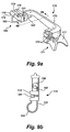
- FIG. 9A is a perspective view of the retainer clip inserted into the channel assembly of the loading tool according to principles described herein.
- FIG. 9B is a cross sectional view of the retainer clip inserted into the channel assembly taken along the perspective line indicated in FIG. 9A .
- FIGS. 10A-10E illustrate an exemplary method of loading a pre-curved electrode array onto a stylet of an insertion tool according to principles described herein.
- FIG. 11 is a perspective view of an alternative loading tool according to principles described herein.
- FIG. 12 is a perspective view of an insertion tool coupled to the loading tool of FIG. 11 according to principles described herein.
- FIG. 13A is a perspective view of an alternative loading tool configured to facilitate the loading of a pre-curved electrode array onto a stylet of an insertion tool according to principles described herein.
- FIG. 13B is a top view of the loading tool shown in FIG. 13A according to principles described herein.
- FIG. 14 is a perspective view of the retainer clip inserted into the channel assembly of the loading tool described in connection with FIGS. 13A-13B according to principles described herein.
- FIG. 15 is a perspective view of the loading tool described in connection with FIGS. 13A-13B with the insertion tool placed therein according to principles described herein.
- FIG. 16 shows the loading tool described in connection with FIGS. 13A-13B with the insertion tool removed therefrom according to principles described herein.
- An exemplary loading tool includes a docking assembly, a channel assembly, and a connecting member configured to connect the channel assembly to the docking assembly and maintain a distance therebetween.
- the docking assembly is configured to couple to the stylet.
- the channel assembly includes a channel configured to receive and allow passage therethrough of the pre-curved electrode array. The channel is aligned with the docking assembly such that when the stylet is coupled to the docking assembly, the stylet is located at least partially within the channel. In this manner, as will be described in more detail below, the electrode array may be advanced through the channel and loaded onto the stylet.
- FIG. 1 illustrates an exemplary cochlear implant system 100 that may be used in accordance with the present systems and methods.
- Exemplary cochlear implant systems suitable for use as described herein include, but are not limited to, those disclosed in U.S. Pat. Nos. 6,219,580; 6,272,382; and 6,308,101, all of which are incorporated herein by reference in their respective entireties.
- the cochlear implant system 100 of FIG. 1 includes a signal processor portion 101 and a cochlear stimulation portion 102 .
- the signal processor portion 101 may include a microphone 103 , a signal processor (SP) 105 , and/or additional circuitry as may serve a particular application.
- the cochlear stimulation portion 102 may include an implantable cochlear stimulator (ICS) 107 , a pre-curved electrode array 108 , and/or additional circuitry as may serve a particular application.
- ICS implantable cochlear stimulator
- the microphone 103 of FIG. 1 is configured to sense acoustic signals and convert the sensed signals to corresponding electrical signals.
- the electrical signals are sent from the microphone 103 to the SP 105 via a communication link 104 .
- the microphone 103 may be connected directly to, or integrated with, the SP 105 .
- the SP 105 processes these converted acoustic signals in accordance with a selected signal processing strategy to generate appropriate stimulation parameters for controlling the ICS 107 . These parameters may specify or define the polarity, magnitude, location (i.e., which electrode pair or electrode group receive the stimulation current), and timing (i.e., when the stimulation current is to be applied to a particular electrode pair) of the electrical stimulation pulses that are generated by the ICS 107 .
- the pre-curved electrode array 108 of FIG. 1 is configured to be inserted within a duct of the cochlea. As shown in FIG. 1 , the electrode array 108 includes a multiplicity of electrodes 109 , e.g., sixteen electrodes, spaced along its length. It will be understood, however, that any number of electrodes 109 may be included within the electrode array 108 .
- the electrode array 108 will be described in more detail below.
- Electronic circuitry within the ICS 107 is configured to generate stimulation current via selected pairs or groups of the individual electrodes 109 in accordance with a specified stimulation pattern defined by the SP 105 .
- the ICS 107 and the SP 105 may be electronically connected via a suitable data or communication link 106 .
- the data communication link 106 may include a bidirectional communication link and/or one or more dedicated unidirectional communication links, such as the forward and back-telemetry links 103 , 104 shown in FIG. 1 .
- the SP 105 and the microphone 103 comprise an external portion of the cochlear implant system 100 and the ICS 107 and the electrode array 108 comprise an implantable portion of the system 100 that is implanted within a patient's body. In alternative embodiments, one or more portions of the SP 105 are included within the implantable portion of the cochlear implant system 100 .
- the external and implantable portions of the cochlear implant system 100 may each include one or more coils configured to transmit and receive power and/or control signals via the communication link 106 .
- the external portion of the cochlear implant system 100 may include an external coil (not shown) and the implantable portion of the cochlear implant system 100 may include an implantable coil (not shown).
- the external coil and the implantable coil may be inductively coupled to each other, thereby allowing data to be transmitted therebetween.
- the data may include, for example, the magnitude and polarity of a sensed acoustic signal.
- the external coil may also transmit power from the external portion to the implantable portion of the cochlear implant system 100 .
- both the SP 105 and the ICS 107 may be implanted within the patient, either in the same housing or in separate housings. If the SP 105 and the ICS 107 are in the same housing, the communication link 106 may be realized with a direct wire connection within such housing. If the SP 105 and the ICS 107 are in separate housings, the communication link 106 may include one or more inductive links, for example.
- FIG. 2 there is shown a schematic structure of the human cochlea 120 .
- the section of the cochlea 120 from point A to point B, i.e., section AB, has a spiral shape.
- the section from point B to point C, i.e., section BC is almost straight.
- the area of stimulation, i.e., the location of the spiral ganglion cells is marked with X's and is separated from the duct of the cochlea 120 by the modiolar wall 121 .
- a pre-curved electrode array 108 is provided as shown in FIG. 3 .
- the electrode array 108 may be substantially as shown and described in U.S. Pat. Nos. 4,819,647, 6,129,753, or 6,604,283, each of which is incorporated herein by reference in its respective entirety.
- the pre-curved array 108 has the same general curvature as that of the cochlea 120 .
- the array 108 includes an elongate flexible carrier 130 having an array of electrode contacts 109 connected to corresponding insulated wires 131 .
- the elongate flexible carrier 130 may be made out of any suitable material such as, but not limited to, silastic, silicone rubber, or plastic and has a hole or lumen 132 passing therethrough.
- the carrier 130 is constructed so as to have a built-in bias or memory force which forces the carrier 130 to naturally assume the spiral or curved shape shown in FIG. 3 .
- the material of the carrier 130 is also configured to allow the carrier 130 to be straightened when loaded on a stylet. Once inserted within the duct of the cochlea 120 , the memory force of the carrier 130 forces the carrier 130 to return to the desired curvature, e.g., as shown in FIG. 3 .
- the wires 131 exit the carrier 130 near a proximal end thereof and form a cable 133 that connects with the ICS 107 .
- the ICS 107 is thus able to make electrical connection with each of the electrode contacts 109 through one or more of the wires 131 .
- the electrode contacts 109 of the array 108 are configured to be positioned along the medial electrode wall following the line between points A′, B′ and C′. This line, as shown in FIG. 3 , is along a portion of the curve or spiral that is generally concave.
- the pre-curved electrode array 108 often has to be loaded onto a stylet before the array 108 can be implanted within a duct of the cochlea.
- the stylet is coupled to or a part of an insertion tool.
- a stand-alone stylet may alternatively be used in connection with the systems and methods described herein.
- FIG. 4 is a perspective view of an exemplary insertion tool 140 that may be used to insert the pre-curved electrode array 108 into a duct of the cochlea. It will be recognized that the insertion tool 140 shown in FIG. 4 is merely exemplary and that many different variations thereof may be used in connection with the methods and systems described herein.
- the insertion tool 140 includes a stylet 141 and a guiding assembly 142 each coupled at a proximal end to an elongate handle 143 .
- the stylet 141 as will be described in more detail below, has a tapered distal tip and is configured to be inserted within the lumen 132 of electrode array 108 .
- the guiding assembly 142 runs parallel to the stylet 141 and is configured to assist in guiding the stylet 141 and electrode array 108 into a duct of the cochlea.
- Both the stylet 141 and guiding assembly 142 may be made out of any suitable material with sufficient stiffness so as to facilitate entry into the cochlea.
- the stylet 141 and/or guiding assembly 142 may be made out of a metal, a metal alloy, a hard plastic, or any other suitable material.
- the handle 143 may extend at a bent angle from where it is coupled to the stylet 141 and guiding assembly 143 to facilitate a more convenient handling or holding thereof.
- the handle 143 may include one or more notches 144 or other types of coupling members or devices to facilitate coupling thereof to a loading tool.
- the handle 143 may be made out of any suitable material as may serve a particular application.
- FIG. 5 illustrates an exemplary loading tool 150 that is often used to load the pre-curved array 108 onto the stylet 141 of an insertion tool 140 .
- the loading tool 150 includes a tube 151 with an elongate hollow lumen extending therethrough 151 .
- the tube 151 is coupled at one of its ends to a bent handle 152 .
- the hollow tube 151 includes an opening at both of its ends to allow passage therethrough of the electrode array 108 and stylet 141 .
- the tube 151 has a length at least as long as the length of the pre-curved array 108 in a straightened state.
- the electrode array 108 is inserted into the lumen of the tube 151 prior to being loaded onto the stylet 141 of the insertion device 140 .
- the diameter of the lumen is such that the electrode array 108 becomes substantially straight as it is inserted therein.
- the stylet 141 may then be inserted into the lumen 132 of the electrode array 108 .
- FIG. 6 shows an exemplary pre-curved electrode array 108 that has been inserted into the lumen of the loading tool 150 of FIG. 5 .
- the electrode array 108 has a wave-type shape and is not completely straight.
- the stylet 141 may puncture the electrode array's lumen 132 or otherwise cause damage to the electrode array 108 when inserted into the electrode array's lumen 132 .
- FIG. 7A is a perspective view of a loading tool 170 configured to facilitate the loading of a pre-curved electrode array 108 onto a stylet 141 of an insertion tool 140 .
- FIG. 7B is a top view of the loading tool 170 shown in FIG. 7A .
- the loading tool 170 allows a surgeon or other user thereof to load a pre-curved electrode array 108 onto a stylet 141 without first having to completely straighten the pre-curved electrode array 108 .
- the loading tool 170 may include a docking assembly 171 , a channel assembly 172 , and a c-shaped connecting member 173 extending therebetween. Each of these components will be described in more detail below. It will be recognized that the loading tool 170 shown in FIGS. 7A-7B is merely illustrative of the many different loading tools that may be used in connection with the methods and systems described herein. Alternative loading tools that may be used will be described in more detail below.
- the docking assembly 171 is located at a proximal end of the loading tool 170 and includes one or more notches 174 configured to mate with the notches 144 in the handle 143 of the insertion tool 140 . In this manner, as will be described in more detail below, the insertion tool 140 may be set or docked within the docking assembly 171 .
- the docking assembly 171 may also include one or more flanges 177 configured to facilitate handling of the loading tool 170 .
- the flanges 177 may have any suitable shape and size as may serve a particular application.
- the channel assembly 172 includes a channel 175 extending therethrough.
- the channel 172 is uncovered from the top and may have any suitable depth as may serve a particular application.
- the pre-curved electrode array 108 may be placed within and pulled through the channel 172 to load the array 108 onto the stylet 141 .
- the channel 172 may have any suitable width that allows for placement of the pre-curved electrode 108 therein.
- the top distal corner of the channel 172 is curved or rounded so as to facilitate easier passage of the pre-curved electrode 108 therethrough.
- the channel 175 is aligned linearly with the docking assembly 171 .
- a distal portion of the stylet 141 may be located within at least a portion of the channel 175 when the insertion tool 140 is docked with the docking assembly 171 of the loading tool 170 .
- the channel assembly 172 may further include wall members 176 on either side of the channel 175 .
- the wall members 176 may be configured to prevent the electrode array 108 from moving laterally within the channel 175 .
- the distal ends of the wall members 176 may be angled or tapered away from the distal end of the channel 175 . In this manner, the wall members 176 may be further configured to guide the electrode array 108 into the channel 175 as the electrode array 108 is being pulled therethrough.
- the c-shaped connecting member 173 is configured to connect the docking assembly 171 to the channel assembly 172 . It will be recognized that the connecting member 173 may have any alternative shape as may serve a particular application.
- one or more of the components of the loading tool 170 may be made out of any biocompatible material as may serve a particular application.
- the loading tool 170 may be made out of polysulfone, plastic, or metal.
- the loading tool 170 is made out of a material that can be sterilized.
- the loading tool 170 may be made out of a single mold. In this manner, the loading tool 170 may be manufactured using any suitable plastic injection molding process. Alternatively, as will be described in more detail below, the components of the loading tool 170 may be coupled together using any other method.
- FIG. 8A is a perspective view of an exemplary retainer clip 180 and FIG. 8B is a side view of the retainer clip 180 of FIG. 8A .
- the retainer clip 180 may include two substantially straight members 181 and 182 with a curved member 183 positioned therebetween.
- the straight members 181 and 182 are configured to be inserted into corresponding holes located within the loading tool 170 .
- the bottom straight member 182 is longer than the top straight member 181 .
- the curved member 180 is configured to be used as a handle for a surgeon or other user. It will be recognized that the retainer clip 180 shown in FIGS. 8A-8B is merely exemplary and that any other type of retainer clip or securing device may additionally or alternatively be used to secure the stylet 141 within the channel 175 .
- FIG. 9A is a perspective view of the retainer clip 180 inserted into the channel assembly 172 of the loading tool 170 .
- FIG. 9B is a cross sectional view of the retainer clip 180 inserted into the channel assembly 172 taken along the perspective line indicated in FIG. 9A .
- the straight members 181 and 182 of the retainer clip 180 are inserted into corresponding holes that pass laterally through the channel assembly 172 .
- the holes are positioned such that the top member 181 is above the channel 175 and the bottom member 182 is beneath the channel 175 .
- the distal end 190 of the bottom straight member 182 may be bent at an angle after it is inserted within the channel assembly 172 . In this manner, the retainer clip 180 may be prevented from completely coming out of the channel assembly 172 if pulled too far.
- the retainer clip 180 is first disengaged or pulled away from the channel assembly 175 until the shorter top member 181 of the retainer clip 180 does not cover the channel 175 .
- the stylet 141 may then be placed within the channel 175 .
- the retainer clip 180 may then be engaged or pushed through the holes in the channel assembly 170 until the top member 181 covers a portion of the stylet 141 that is within the channel 175 .
- FIGS. 10A-10E An exemplary method of loading the pre-curved electrode array 108 onto a stylet 141 of an insertion tool 140 will now be described in connection with FIGS. 10A-10E . It will be recognized that the steps illustrated in FIGS. 10A-10E are merely exemplary and that they may be reordered, modified, or otherwise varied as may serve a particular application.
- the distal portion of the stylet 141 is first inserted into a proximal portion of the lumen 132 of the electrode array 108 .
- the proximal portion of the lumen 132 into which the stylet 141 is inserted is relatively straight.
- the insertion tool 140 is placed within the loading tool 170 .
- the insertion tool 140 may be placed such that the notches 144 thereof are aligned with the notches 174 of the loading tool 170 .
- the insertion tool 140 is placed such that the distal tip of the stylet 141 and the proximal portion of the electrode array 108 are located within the channel 175 of the loading tool 170 .
- the retainer clip 180 may then be engaged to secure the distal portion of the stylet 141 within the channel 175 .
- the surgeon or other user may load the electrode array 108 onto the stylet 141 by pulling the cable 133 of the electrode array 108 in a direction indicated by the arrow shown in FIG. 10C .
- the pre-curved portion of the electrode array 108 enters the channel 145 and is loaded onto the stylet 141 . In this manner, the electrode array 108 does not have to be completely straightened prior to being loaded onto the stylet 141 .
- the retainer clip 180 may be disengaged from the channel assembly 172 , as shown in FIG. 10 D.
- the insertion tool 140 may then be removed from the loading tool 170 , as shown in FIG. 10E .
- the stylet 141 has been completely inserted within the lumen 132 of the electrode array 108 .
- the electrode array 108 may then be inserted within a duct of the cochlea using any suitable insertion procedure.
- FIG. 11 is a perspective view of an alternative loading tool 210 that may be used in connection with the methods and systems described herein.
- the loading tool 210 also includes a docking assembly 211 , a channel assembly 212 and a connecting member 213 .
- the docking assembly 211 is located at a proximal end of the loading tool 210 and includes a lumen 214 extending therethrough. As will be described in more detail below, the insertion tool 140 may be inserted through the lumen 214 of the docking assembly 211 and coupled thereto.
- the channel assembly 212 includes a channel guide 215 .
- the channel guide 215 serves a similar purpose to that of the channel 175 described in connection with FIGS. 7A-7B and is configured to allow for placement of the pre-curved electrode 108 therein.
- the channel guide 215 is curved so as to facilitate easier passage of the pre-curved electrode 108 therethrough.
- FIG. 11 the channel guide 215 is aligned linearly with the lumen 214 of the docking assembly 211 .
- a distal portion of the stylet 141 may be placed within at least a portion of the channel guide 215 when the insertion tool 140 is docked with the docking assembly 211 of the loading tool 210 .
- FIG. 12 is a perspective view of an insertion tool 140 coupled to the loading tool 210 of FIG. 11 .
- a distal portion of the stylet 141 is located within the channel guide 215 .
- the electrode array 108 may be loaded onto the stylet 141 in a manner similar to that described in connection with FIGS. 10A-10E .
- the components of the loading tool 210 shown in FIG. 11 may be made out of any biocompatible material as may serve a particular application.
- the loading tool 210 may be made out of polysulfone, plastic, or metal.
- the loading tool 210 is made out of a material that can be sterilized.
- FIG. 13A is a perspective view of an alternative loading tool 230 that may be used in connection with the methods and systems described herein.
- FIG. 13B is a top view of the loading tool 230 shown in FIG. 13A .
- the loading tool 230 may include a docking assembly 231 , a channel assembly 232 , and a connecting member 233 extending therebetween. Each of these components will be described in more detail below.
- the docking assembly 231 is located at a proximal end of the loading tool 230 and includes one or more notches 234 configured to mate with the notches 144 in the handle 143 of the insertion tool 140 . In this manner, the insertion tool 140 may be set or docked within the docking assembly 231 .
- the docking assembly 231 may also include one or more flanges 237 configured to facilitate handling of the loading tool 230 .
- the flanges 237 may have any suitable shape and size as may serve a particular application.
- one or more of the flanges 237 may include laser etched wording.
- the channel assembly 232 includes a channel 235 extending therethrough.
- the channel 235 is uncovered from the top and may have any suitable depth as may serve a particular application.
- the pre-curved electrode array 108 may be placed within and pulled through the channel 235 to load the array 108 onto the stylet 141 .
- the channel 235 may have any suitable width that allows for placement of the pre-curved electrode 108 therein.
- the top distal corner of the channel 235 is curved or rounded so as to facilitate easier passage of the pre-curved electrode 108 therethrough.
- the channel 235 is aligned linearly with the docking assembly 231 .
- a distal portion of the stylet 141 may be located within at least a portion of the channel 235 when the insertion tool 140 is docked with the docking assembly 231 of the loading tool 230 .
- the channel assembly 232 may further include wall members 236 on either side of the channel 235 .
- the wall members 236 may be configured to prevent the electrode array 108 from moving laterally within the channel 235 .
- the distal ends of the wall members 236 may be angled or tapered away from the distal end of the channel 235 . In this manner, the wall members 236 may be further configured to guide the electrode array 108 into the channel 235 as the electrode array 108 is being pulled therethrough.
- the connecting member 233 is configured to connect the docking assembly 231 to the channel assembly 232 .
- the connecting member 233 includes a finger grip 238 configured to facilitate easier handling thereof.
- the finger grip 238 may include a lumen extending therethrough, as shown in FIG. 13A . Additionally or alternatively, the finger grip 238 may include any other structure as may serve a particular application.
- one or more of the components of the loading tool 230 may be made out of any biocompatible material as may serve a particular application.
- the loading tool 230 may be made out of polysulfone, plastic, or metal.
- the loading tool 230 is made out of a material that can be sterilized.
- the loading tool 230 may be made out of a single mold. In this manner, the loading tool 230 may be manufactured using any suitable plastic injection molding process. Alternatively, as will be described in more detail below, the components of the loading tool 230 may be coupled together using any other method.
- FIG. 14 is a perspective view of the retainer clip 180 inserted into the channel assembly 232 of the loading tool 230 described in connection with FIGS. 13A-13B .
- the straight members 181 and 182 of the retainer clip 180 are inserted into corresponding holes that pass laterally through the channel assembly 232 .
- the holes are positioned such that the top member 181 is above the channel 235 and the bottom member 182 is beneath the channel 235 .
- the distal end 190 of the bottom straight member 182 may be bent at an angle after it is inserted within the channel assembly 232 . In this manner, the retainer clip 180 may be prevented from completely coming out of the channel assembly 232 if pulled too far.
- the retainer clip 180 is first disengaged or pulled away from the channel assembly 235 until the shorter top member 181 of the retainer clip 180 does not cover the channel 235 .
- the stylet 141 may then be placed within the channel 235 .
- the retainer clip 180 may then be engaged or pushed through the holes in the channel assembly 230 until the top member 181 covers a portion of the stylet 141 that is within the channel 235 .
- FIG. 15 is a perspective view of the loading tool 230 with the insertion tool 140 placed therein.
- the insertion tool 140 may be placed such that the notches 144 thereof are aligned with the notches 234 of the loading tool 230 .
- the insertion tool 140 is placed such that the distal tip of the stylet 141 and the proximal portion of the electrode array 108 are located within the channel 235 of the loading tool 230 .
- FIG. 16 shows the loading tool 230 with the insertion tool 140 removed therefrom.
Abstract
Description
Claims (13)
Priority Applications (3)
| Application Number | Priority Date | Filing Date | Title |
|---|---|---|---|
| US11/933,861 US8915926B2 (en) | 2006-11-08 | 2007-11-01 | Pre-curved electrode array loading tools |
| PCT/US2007/083428 WO2008057989A2 (en) | 2006-11-08 | 2007-11-02 | Pre-curved electrode array loading tools |
| US12/485,427 US8939993B1 (en) | 2006-11-08 | 2009-06-16 | Pre-curved electrode array loading tools |
Applications Claiming Priority (3)
| Application Number | Priority Date | Filing Date | Title |
|---|---|---|---|
| US85808706P | 2006-11-08 | 2006-11-08 | |
| US92552607P | 2007-04-20 | 2007-04-20 | |
| US11/933,861 US8915926B2 (en) | 2006-11-08 | 2007-11-01 | Pre-curved electrode array loading tools |
Related Parent Applications (1)
| Application Number | Title | Priority Date | Filing Date |
|---|---|---|---|
| US85808706P Continuation | 2006-11-08 | 2006-11-08 |
Related Child Applications (1)
| Application Number | Title | Priority Date | Filing Date |
|---|---|---|---|
| US12/485,427 Continuation-In-Part US8939993B1 (en) | 2006-11-08 | 2009-06-16 | Pre-curved electrode array loading tools |
Publications (2)
| Publication Number | Publication Date |
|---|---|
| US20080109011A1 US20080109011A1 (en) | 2008-05-08 |
| US8915926B2 true US8915926B2 (en) | 2014-12-23 |
Family
ID=39360629
Family Applications (1)
| Application Number | Title | Priority Date | Filing Date |
|---|---|---|---|
| US11/933,861 Expired - Fee Related US8915926B2 (en) | 2006-11-08 | 2007-11-01 | Pre-curved electrode array loading tools |
Country Status (1)
| Country | Link |
|---|---|
| US (1) | US8915926B2 (en) |
Families Citing this family (26)
| Publication number | Priority date | Publication date | Assignee | Title |
|---|---|---|---|---|
| US6702811B2 (en) * | 1999-04-05 | 2004-03-09 | Medtronic, Inc. | Ablation catheter assembly with radially decreasing helix and method of use |
| US7653438B2 (en) | 2002-04-08 | 2010-01-26 | Ardian, Inc. | Methods and apparatus for renal neuromodulation |
| US8774913B2 (en) | 2002-04-08 | 2014-07-08 | Medtronic Ardian Luxembourg S.A.R.L. | Methods and apparatus for intravasculary-induced neuromodulation |
| US8939993B1 (en) | 2006-11-08 | 2015-01-27 | Advanced Bionics Ag | Pre-curved electrode array loading tools |
| US8915926B2 (en) | 2006-11-08 | 2014-12-23 | Advanced Bionics Ag | Pre-curved electrode array loading tools |
| US9474546B1 (en) | 2008-04-18 | 2016-10-25 | Advanced Bionics Ag | Pre-curved electrode array insertion tools |
| US8880193B1 (en) | 2009-05-22 | 2014-11-04 | Advanced Bionics, Llc | Cochlear electrode array |
| WO2011005993A1 (en) * | 2009-07-08 | 2011-01-13 | Advanced Bionics, Llc | Lead insertion tools |
| US8712554B2 (en) * | 2009-07-21 | 2014-04-29 | Advanced Bionics | Integrated wire carrier for electrode array |
| EP2566425B1 (en) | 2010-05-07 | 2018-12-19 | Advanced Bionics AG | Systems and methods for loading a pre-curved electrode array onto a straightening member |
| WO2011140452A2 (en) | 2010-05-07 | 2011-11-10 | Advanced Bionics Ag | Systems and methods for loading a pre-curved electrode array onto a straightening member |
| US9037267B2 (en) | 2010-05-27 | 2015-05-19 | Advanced Bionics Llc | Cochlear lead |
| US9033869B2 (en) | 2010-05-27 | 2015-05-19 | Advanced Bionics, Llc | Cochlear lead |
| US8774944B2 (en) | 2010-06-25 | 2014-07-08 | Advanced Bionics Ag | Tools, systems, and methods for inserting an electrode array portion of a lead into a bodily orifice |
| US8753352B2 (en) | 2010-06-25 | 2014-06-17 | Advanced Bionics Ag | Tools, systems, and methods for inserting a pre-curved electrode array portion of a lead into a bodily orifice |
| US8753353B2 (en) | 2010-06-25 | 2014-06-17 | Advanced Bionics Ag | Tools, systems, and methods for inserting an electrode array portion of a lead into a bodily orifice |
| US8473075B2 (en) | 2010-06-25 | 2013-06-25 | Advanced Bionics | Cochlear implant system with removable stylet |
| US20120083713A1 (en) * | 2010-09-30 | 2012-04-05 | Emory University | Device for gauging a force threshold and engaging a target of interest |
| WO2012061164A1 (en) | 2010-10-25 | 2012-05-10 | Kevin Mauch | Catheter apparatuses having multi-electrode arrays for renal neuromodulation and associated systems and methods |
| BR112014028131A2 (en) | 2012-05-11 | 2017-06-27 | Medtronic Ardian Luxembourg | catheter apparatus, renal neuromodulation system, and method for performing renal neuromodulation |
| US9095321B2 (en) | 2012-11-21 | 2015-08-04 | Medtronic Ardian Luxembourg S.A.R.L. | Cryotherapeutic devices having integral multi-helical balloons and methods of making the same |
| US9179974B2 (en) | 2013-03-15 | 2015-11-10 | Medtronic Ardian Luxembourg S.A.R.L. | Helical push wire electrode |
| AU2014293432A1 (en) * | 2013-07-26 | 2016-02-18 | Med-El Elektromedizinische Geraete Gmbh | Cochlear implant electrode insertion support device |
| US20150073515A1 (en) | 2013-09-09 | 2015-03-12 | Medtronic Ardian Luxembourg S.a.r.I. | Neuromodulation Catheter Devices and Systems Having Energy Delivering Thermocouple Assemblies and Associated Methods |
| JP2017513600A (en) | 2014-04-24 | 2017-06-01 | メドトロニック アーディアン ルクセンブルク ソシエテ ア レスポンサビリテ リミテ | Nerve adjustment catheter with braided shaft and related systems and methods |
| CN109954210A (en) * | 2019-03-18 | 2019-07-02 | 上海力声特医学科技有限公司 | Artificial cochlea's cranked electrode implanting device |
Citations (31)
| Publication number | Priority date | Publication date | Assignee | Title |
|---|---|---|---|---|
| EP0109304A1 (en) | 1982-11-15 | 1984-05-23 | Minnesota Mining And Manufacturing Company | Anchor and insertion tool for anchoring electrode leads used in cochlear implantation |
| WO1989000870A1 (en) | 1987-07-24 | 1989-02-09 | Cochlear Pty. Ltd. | Apparatus and method for insertion of cochlear electrode assembly |
| US4819647A (en) | 1984-05-03 | 1989-04-11 | The Regents Of The University Of California | Intracochlear electrode array |
| US4898183A (en) | 1987-07-24 | 1990-02-06 | Cochlear Pty. Limited | Apparatus and method for insertion of cochlear electrode assembly |
| WO1993024058A1 (en) | 1992-05-29 | 1993-12-09 | Cochlear Pty. Limited | Electrode insertion tool |
| US5314411A (en) * | 1989-07-24 | 1994-05-24 | Steven F. Bierman, M.D. | Catheterization system with universal retention device and method of use |
| US5443493A (en) | 1989-09-22 | 1995-08-22 | Alfred E. Mann Foundation For Scientific Research | Cochlea stimulating electrode assembly, insertion tool, holder and method of implantation |
| WO1997020530A1 (en) | 1995-12-04 | 1997-06-12 | Cochlear Corporation | Device and method for inserting a flexible element into soft tissue |
| US6070105A (en) | 1997-09-02 | 2000-05-30 | Advanced Bionics Corporation | Modiolus-hugging cochlear electrodes |
| US6125302A (en) | 1997-09-02 | 2000-09-26 | Advanced Bionics Corporation | Precurved modiolar-hugging cochlear electrode |
| US6129753A (en) | 1998-03-27 | 2000-10-10 | Advanced Bionics Corporation | Cochlear electrode array with electrode contacts on medial side |
| US6149657A (en) | 1998-06-02 | 2000-11-21 | Advanced Bionics Corporation | Insertion tool for placement of a flexible silicone mold or positioner within a cochlea |
| WO2000071063A1 (en) | 1999-05-21 | 2000-11-30 | Cochlear Limited | A cochlear implant electrode array |
| US6195586B1 (en) | 1998-08-26 | 2001-02-27 | Advanced Bionics Corporation | Space-filling cochlear electrode |
| US6219580B1 (en) | 1995-04-26 | 2001-04-17 | Advanced Bionics Corporation | Multichannel cochlear prosthesis with flexible control of stimulus waveforms |
| US6272382B1 (en) | 1998-07-31 | 2001-08-07 | Advanced Bionics Corporation | Fully implantable cochlear implant system |
| US6308101B1 (en) | 1998-07-31 | 2001-10-23 | Advanced Bionics Corporation | Fully implantable cochlear implant system |
| WO2002030507A1 (en) | 2000-10-11 | 2002-04-18 | Cochlear Limited | Double stylet insertion tool for a cochlear implant electrode array |
| WO2002032498A1 (en) | 2000-10-17 | 2002-04-25 | Cochlear Limited | Insertion tool for a cochlear implant electrode array |
| US20020111634A1 (en) * | 2000-08-30 | 2002-08-15 | Johns Hopkins University | Controllable motorized device for percutaneous needle placement in soft tissue target and methods and systems related thereto |
| WO2002074211A1 (en) | 2001-03-19 | 2002-09-26 | Cochlear Limited | Insertion tool system for an electrode array |
| WO2003070133A1 (en) | 2002-02-22 | 2003-08-28 | Cochlear Limited | An insertion device for an electrode array |
| WO2004012809A1 (en) | 2002-08-06 | 2004-02-12 | Neopraxis Pty Ltd | A method and system for inserting an electrode |
| US20040243177A1 (en) | 2003-04-17 | 2004-12-02 | Martin Svehla | Manual insertion tool for a cochlear implant |
| US20050251237A1 (en) | 2004-05-10 | 2005-11-10 | Advanced Bionics Corporation | Implantable electrode, insertion tool for use therewith, and insertion method |
| US6968238B1 (en) | 1998-08-26 | 2005-11-22 | Kuzma Janusz A | Method for inserting cochlear electrode and insertion tool for use therewith |
| US20050267555A1 (en) | 2004-05-28 | 2005-12-01 | Marnfeldt Goran N | Engagement tool for implantable medical devices |
| US7050858B1 (en) | 2001-04-06 | 2006-05-23 | Advanced Bionics Corporation | Insertion tool for placement of electrode system inside the cochlear lumen |
| US20080109011A1 (en) | 2006-11-08 | 2008-05-08 | Advanced Bionics Corporation | Pre-curved electrode array loading tools |
| WO2008057989A2 (en) | 2006-11-08 | 2008-05-15 | Advanced Bionics Corporation | Pre-curved electrode array loading tools |
| US20080294174A1 (en) | 2007-05-21 | 2008-11-27 | Epitek, Inc. | Methods and apparatus for pericardial access |
Family Cites Families (2)
| Publication number | Priority date | Publication date | Assignee | Title |
|---|---|---|---|---|
| US267555A (en) * | 1882-11-14 | Andreas meohwaet | ||
| US294174A (en) * | 1884-02-26 | Isaac f |
-
2007
- 2007-11-01 US US11/933,861 patent/US8915926B2/en not_active Expired - Fee Related
Patent Citations (45)
| Publication number | Priority date | Publication date | Assignee | Title |
|---|---|---|---|---|
| EP0109304A1 (en) | 1982-11-15 | 1984-05-23 | Minnesota Mining And Manufacturing Company | Anchor and insertion tool for anchoring electrode leads used in cochlear implantation |
| US4819647A (en) | 1984-05-03 | 1989-04-11 | The Regents Of The University Of California | Intracochlear electrode array |
| WO1989000870A1 (en) | 1987-07-24 | 1989-02-09 | Cochlear Pty. Ltd. | Apparatus and method for insertion of cochlear electrode assembly |
| EP0328597A1 (en) | 1987-07-24 | 1989-08-23 | Cochlear Pty. Ltd. | Apparatus and method for insertion of cochlear electrode assembly |
| US4898183A (en) | 1987-07-24 | 1990-02-06 | Cochlear Pty. Limited | Apparatus and method for insertion of cochlear electrode assembly |
| US5314411A (en) * | 1989-07-24 | 1994-05-24 | Steven F. Bierman, M.D. | Catheterization system with universal retention device and method of use |
| US5443493A (en) | 1989-09-22 | 1995-08-22 | Alfred E. Mann Foundation For Scientific Research | Cochlea stimulating electrode assembly, insertion tool, holder and method of implantation |
| WO1993024058A1 (en) | 1992-05-29 | 1993-12-09 | Cochlear Pty. Limited | Electrode insertion tool |
| US6219580B1 (en) | 1995-04-26 | 2001-04-17 | Advanced Bionics Corporation | Multichannel cochlear prosthesis with flexible control of stimulus waveforms |
| WO1997020530A1 (en) | 1995-12-04 | 1997-06-12 | Cochlear Corporation | Device and method for inserting a flexible element into soft tissue |
| US5667514A (en) | 1995-12-04 | 1997-09-16 | Cochlear Ltd. | Device and method for inserting a flexible element into soft tissue |
| US6070105A (en) | 1997-09-02 | 2000-05-30 | Advanced Bionics Corporation | Modiolus-hugging cochlear electrodes |
| US6125302A (en) | 1997-09-02 | 2000-09-26 | Advanced Bionics Corporation | Precurved modiolar-hugging cochlear electrode |
| US6604283B1 (en) | 1997-09-02 | 2003-08-12 | Advanced Bionics Corporation | Method of making precurved, modiolar-hugging cochlear electrode |
| US6129753A (en) | 1998-03-27 | 2000-10-10 | Advanced Bionics Corporation | Cochlear electrode array with electrode contacts on medial side |
| US6149657A (en) | 1998-06-02 | 2000-11-21 | Advanced Bionics Corporation | Insertion tool for placement of a flexible silicone mold or positioner within a cochlea |
| US6272382B1 (en) | 1998-07-31 | 2001-08-07 | Advanced Bionics Corporation | Fully implantable cochlear implant system |
| US6308101B1 (en) | 1998-07-31 | 2001-10-23 | Advanced Bionics Corporation | Fully implantable cochlear implant system |
| US6195586B1 (en) | 1998-08-26 | 2001-02-27 | Advanced Bionics Corporation | Space-filling cochlear electrode |
| US6968238B1 (en) | 1998-08-26 | 2005-11-22 | Kuzma Janusz A | Method for inserting cochlear electrode and insertion tool for use therewith |
| WO2000071063A1 (en) | 1999-05-21 | 2000-11-30 | Cochlear Limited | A cochlear implant electrode array |
| US6421569B1 (en) | 1999-05-21 | 2002-07-16 | Cochlear Limited | Cochlear implant electrode array |
| US20020111634A1 (en) * | 2000-08-30 | 2002-08-15 | Johns Hopkins University | Controllable motorized device for percutaneous needle placement in soft tissue target and methods and systems related thereto |
| WO2002030507A1 (en) | 2000-10-11 | 2002-04-18 | Cochlear Limited | Double stylet insertion tool for a cochlear implant electrode array |
| US20080004684A1 (en) | 2000-10-11 | 2008-01-03 | Cochlear Limited | Double stylet insertion tool for a cochlear implant electrode array |
| US7269461B2 (en) | 2000-10-11 | 2007-09-11 | Cochlear Limited | Double stylet insertion tool for a cochlear implant electrode array |
| EP1341578A1 (en) | 2000-10-11 | 2003-09-10 | Cochlear Limited | Double stylet insertion tool for a cochlear implant electrode array |
| US20030093139A1 (en) | 2000-10-17 | 2003-05-15 | Peter Gibson | Insertion tool for a cochlear implant electrode array |
| WO2002032498A1 (en) | 2000-10-17 | 2002-04-25 | Cochlear Limited | Insertion tool for a cochlear implant electrode array |
| EP1233810A1 (en) | 2000-10-17 | 2002-08-28 | Cochlear Limited | Insertion tool for a cochlear implant electrode array |
| US7063708B2 (en) | 2001-03-19 | 2006-06-20 | Cochlear Limited | Insertion tool system for an electrode array |
| US20060058861A1 (en) | 2001-03-19 | 2006-03-16 | Cochlear Limited | Insertion tool system for an electrode array |
| WO2002074211A1 (en) | 2001-03-19 | 2002-09-26 | Cochlear Limited | Insertion tool system for an electrode array |
| EP1370205A1 (en) | 2001-03-19 | 2003-12-17 | Cochlear Limited | Insertion tool system for an electrode array |
| US7050858B1 (en) | 2001-04-06 | 2006-05-23 | Advanced Bionics Corporation | Insertion tool for placement of electrode system inside the cochlear lumen |
| WO2003070133A1 (en) | 2002-02-22 | 2003-08-28 | Cochlear Limited | An insertion device for an electrode array |
| US20060241723A1 (en) * | 2002-02-22 | 2006-10-26 | Cochlear Limited | Insertion device for an electrode array |
| EP1476104A1 (en) | 2002-02-22 | 2004-11-17 | Cochlear Limited | An insertion device for an electrode array |
| WO2004012809A1 (en) | 2002-08-06 | 2004-02-12 | Neopraxis Pty Ltd | A method and system for inserting an electrode |
| US20040243177A1 (en) | 2003-04-17 | 2004-12-02 | Martin Svehla | Manual insertion tool for a cochlear implant |
| US20050251237A1 (en) | 2004-05-10 | 2005-11-10 | Advanced Bionics Corporation | Implantable electrode, insertion tool for use therewith, and insertion method |
| US20050267555A1 (en) | 2004-05-28 | 2005-12-01 | Marnfeldt Goran N | Engagement tool for implantable medical devices |
| US20080109011A1 (en) | 2006-11-08 | 2008-05-08 | Advanced Bionics Corporation | Pre-curved electrode array loading tools |
| WO2008057989A2 (en) | 2006-11-08 | 2008-05-15 | Advanced Bionics Corporation | Pre-curved electrode array loading tools |
| US20080294174A1 (en) | 2007-05-21 | 2008-11-27 | Epitek, Inc. | Methods and apparatus for pericardial access |
Non-Patent Citations (5)
| Title |
|---|
| International Search Report and Written Opinion received in International Application No. PCT/US2007/083428, May 20, 2008. |
| International Search Report and Written Opinion received in International Application No. PCT/US2011/035539, dated Dec. 29, 2011. |
| International Search Report and Written Opinion received in International Application No. PCT/US2011/035541, dated Oct. 7, 2011. |
| Non-Final Office Action received in U.S. Appl. No. 12/485,427 dated Feb. 5, 2014. |
| Non-Final Office Action received in U.S. Appl. No. 13/696,789 dated Jan. 14, 2014. |
Also Published As
| Publication number | Publication date |
|---|---|
| US20080109011A1 (en) | 2008-05-08 |
Similar Documents
| Publication | Publication Date | Title |
|---|---|---|
| US8915926B2 (en) | Pre-curved electrode array loading tools | |
| US8452421B2 (en) | Lead insertion tools | |
| US6038484A (en) | Cochlear electrode with modiolar-hugging system including a flexible positioner | |
| US6321125B1 (en) | Cochlear electrode system including distally attached flexible positioner | |
| US6195586B1 (en) | Space-filling cochlear electrode | |
| US8473075B2 (en) | Cochlear implant system with removable stylet | |
| US9037267B2 (en) | Cochlear lead | |
| EP1370205B1 (en) | Insertion tool system for an electrode array | |
| US6070105A (en) | Modiolus-hugging cochlear electrodes | |
| EP2457386B1 (en) | Integrated wire carrier for electrode array | |
| US10016589B2 (en) | Mid-scalar electrode array | |
| US9492654B2 (en) | Cochlear lead | |
| WO2008057989A2 (en) | Pre-curved electrode array loading tools | |
| US9474546B1 (en) | Pre-curved electrode array insertion tools | |
| US8855790B2 (en) | Systems and methods for loading a pre-curved electrode array onto a straightening member | |
| US8954169B2 (en) | Systems and methods for loading a pre-curved electrode array onto a straightening member | |
| US8939993B1 (en) | Pre-curved electrode array loading tools | |
| EP2659930B1 (en) | Cochlear lead |
Legal Events
| Date | Code | Title | Description |
|---|---|---|---|
| AS | Assignment |
Owner name: ADVANCED BIONICS CORPORATION, CALIFORNIA Free format text: ASSIGNMENT OF ASSIGNORS INTEREST;ASSIGNORS:BLOMQUIST, STEVE;KUZMA, JANUSZ A.;ORINSKI, WILLIAM G.;AND OTHERS;REEL/FRAME:020101/0793;SIGNING DATES FROM 20071030 TO 20071101 Owner name: ADVANCED BIONICS CORPORATION, CALIFORNIA Free format text: ASSIGNMENT OF ASSIGNORS INTEREST;ASSIGNORS:BLOMQUIST, STEVE;KUZMA, JANUSZ A.;ORINSKI, WILLIAM G.;AND OTHERS;SIGNING DATES FROM 20071030 TO 20071101;REEL/FRAME:020101/0793 |
|
| AS | Assignment |
Owner name: BOSTON SCIENTIFIC NEUROMODULATION CORPORATION, CAL Free format text: CHANGE OF NAME;ASSIGNOR:ADVANCED BIONICS CORPORATION;REEL/FRAME:020296/0477 Effective date: 20071116 Owner name: BOSTON SCIENTIFIC NEUROMODULATION CORPORATION, CALIFORNIA Free format text: CHANGE OF NAME;ASSIGNOR:ADVANCED BIONICS CORPORATION;REEL/FRAME:020296/0477 Effective date: 20071116 Owner name: BOSTON SCIENTIFIC NEUROMODULATION CORPORATION,CALI Free format text: CHANGE OF NAME;ASSIGNOR:ADVANCED BIONICS CORPORATION;REEL/FRAME:020296/0477 Effective date: 20071116 |
|
| AS | Assignment |
Owner name: ADVANCED BIONICS, LLC, CALIFORNIA Free format text: ASSIGNMENT OF ASSIGNORS INTEREST;ASSIGNOR:BOSTON SCIENTIFIC NEUROMODULATION CORPORATION;REEL/FRAME:020340/0713 Effective date: 20080107 Owner name: ADVANCED BIONICS, LLC,CALIFORNIA Free format text: ASSIGNMENT OF ASSIGNORS INTEREST;ASSIGNOR:BOSTON SCIENTIFIC NEUROMODULATION CORPORATION;REEL/FRAME:020340/0713 Effective date: 20080107 |
|
| FEPP | Fee payment procedure |
Free format text: MAINTENANCE FEE REMINDER MAILED (ORIGINAL EVENT CODE: REM.) |
|
| LAPS | Lapse for failure to pay maintenance fees |
Free format text: PATENT EXPIRED FOR FAILURE TO PAY MAINTENANCE FEES (ORIGINAL EVENT CODE: EXP.); ENTITY STATUS OF PATENT OWNER: LARGE ENTITY |
|
| STCH | Information on status: patent discontinuation |
Free format text: PATENT EXPIRED DUE TO NONPAYMENT OF MAINTENANCE FEES UNDER 37 CFR 1.362 |
|
| FP | Lapsed due to failure to pay maintenance fee |
Effective date: 20181223 |