US8931536B2 - Devices for applying conductive gel-pads to electrodes and electrodes produced thereby - Google Patents
Devices for applying conductive gel-pads to electrodes and electrodes produced thereby Download PDFInfo
- Publication number
- US8931536B2 US8931536B2 US12/176,706 US17670608A US8931536B2 US 8931536 B2 US8931536 B2 US 8931536B2 US 17670608 A US17670608 A US 17670608A US 8931536 B2 US8931536 B2 US 8931536B2
- Authority
- US
- United States
- Prior art keywords
- gel
- electrode
- carriage
- pad
- pressure roller
- Prior art date
- Legal status (The legal status is an assumption and is not a legal conclusion. Google has not performed a legal analysis and makes no representation as to the accuracy of the status listed.)
- Expired - Fee Related, expires
Links
Images


Classifications
-
- A—HUMAN NECESSITIES
- A61—MEDICAL OR VETERINARY SCIENCE; HYGIENE
- A61B—DIAGNOSIS; SURGERY; IDENTIFICATION
- A61B5/00—Measuring for diagnostic purposes; Identification of persons
- A61B5/24—Detecting, measuring or recording bioelectric or biomagnetic signals of the body or parts thereof
- A61B5/25—Bioelectric electrodes therefor
- A61B5/251—Means for maintaining electrode contact with the body
- A61B5/257—Means for maintaining electrode contact with the body using adhesive means, e.g. adhesive pads or tapes
- A61B5/259—Means for maintaining electrode contact with the body using adhesive means, e.g. adhesive pads or tapes using conductive adhesive means, e.g. gels
-
- A61B5/04087—
-
- A—HUMAN NECESSITIES
- A61—MEDICAL OR VETERINARY SCIENCE; HYGIENE
- A61B—DIAGNOSIS; SURGERY; IDENTIFICATION
- A61B2562/00—Details of sensors; Constructional details of sensor housings or probes; Accessories for sensors
- A61B2562/12—Manufacturing methods specially adapted for producing sensors for in-vivo measurements
- A61B2562/125—Manufacturing methods specially adapted for producing sensors for in-vivo measurements characterised by the manufacture of electrodes
-
- Y—GENERAL TAGGING OF NEW TECHNOLOGICAL DEVELOPMENTS; GENERAL TAGGING OF CROSS-SECTIONAL TECHNOLOGIES SPANNING OVER SEVERAL SECTIONS OF THE IPC; TECHNICAL SUBJECTS COVERED BY FORMER USPC CROSS-REFERENCE ART COLLECTIONS [XRACs] AND DIGESTS
- Y10—TECHNICAL SUBJECTS COVERED BY FORMER USPC
- Y10T—TECHNICAL SUBJECTS COVERED BY FORMER US CLASSIFICATION
- Y10T156/00—Adhesive bonding and miscellaneous chemical manufacture
- Y10T156/17—Surface bonding means and/or assemblymeans with work feeding or handling means
-
- Y—GENERAL TAGGING OF NEW TECHNOLOGICAL DEVELOPMENTS; GENERAL TAGGING OF CROSS-SECTIONAL TECHNOLOGIES SPANNING OVER SEVERAL SECTIONS OF THE IPC; TECHNICAL SUBJECTS COVERED BY FORMER USPC CROSS-REFERENCE ART COLLECTIONS [XRACs] AND DIGESTS
- Y10—TECHNICAL SUBJECTS COVERED BY FORMER USPC
- Y10T—TECHNICAL SUBJECTS COVERED BY FORMER US CLASSIFICATION
- Y10T428/00—Stock material or miscellaneous articles
- Y10T428/31504—Composite [nonstructural laminate]
Definitions
- the present invention relates generally to therapeutic devices for applying electric energy to the body and, in particular, to electrodes with conductive gel-pads and assembly devices therefor.
- Electrically conductive adhesive solid hydrogels and liquid gels are used in the medical field to provide an electrical interface to the skin of a subject to couple electrical signals into and/or out of the subject (e.g. for diagnostic and/or monitoring uses) and/or to couple electrical stimulus into the subject (e.g. for treatment and/or preventative uses).
- the application of these conductive materials to electrodes is known. In general, the conductive material is applied to the electrode using sophisticated equipment, where the equipment is located at the manufacturer. Moreover, the conductive material is applied to the electrode in a manner such that the material cannot be removed from the electrode and reused. Thus, these electrodes are intended to be disposable and not reused from patient to patient, making them costly and inefficient to use. This is due to the fact that once the electrode with conductive material has been in contact with a first patient, it is generally not desirable to apply the same electrode with the same conductive material to a different patient.
- Described herein are devices for applying conductive gels to electrodes and the gel-laminated electrodes produced thereby.
- the devices permit the reuse of the electrodes by easily applying fresh gels to them for each subsequent use.
- all of the components of the laminating device are provided in a single housing.
- the gel applying and drive components are housed within the device, and a replaceable cartridge houses the gels and the gel delivery components.
- dispensers for storing and dispensing conductive gels that can be readily applied to and removed from an electrode.
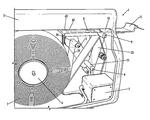
- FIG. 1 is a side perspective view of a portion of a laminating device according to a first example embodiment of the present invention, with a side access door removed to show the internal components of the device.
- FIG. 1A is a side view of a second pressure roller of the device of FIG. 1 that cooperatively compresses gel-pads onto electrodes.
- FIG. 2 is a side view of a roll of conductive gel-pads of the device of FIG. 1 .
- FIG. 3 is a perspective view of the roll of conductive gel-pads of FIG. 2 .
- FIG. 4 a front/side perspective view of the device of FIG. 1 with the side access door opened.
- FIG. 5 is a perspective view of an electrode laminated by the laminating device of FIG. 1 .
- FIG. 6 is a bottom perspective view of the electrode of FIG. 5 showing the gel-pad laminated onto the bottom surface of the electrode.
- FIG. 7 is a top view of a receiving tray and activating mechanism of the device of FIG. 1 .
- FIG. 8 is a top view of a portion of the conductive gel-pad tape of FIG. 2 showing two individual conductive gel-pads.
- FIG. 9 is a perspective view of a conductive gel-pad dispenser according to another aspect of the present invention.
- FIG. 10 is a top perspective view of a portion of the conductive gel dispenser of FIG. 9 with the top door open.
- FIG. 11 is a top perspective view of a portion of the conductive gel dispenser of FIG. 9 with a portion of the sidewall removed to show the internal components.
- FIG. 12 is a left perspective view of a laminating device according to a second example embodiment of the present invention, showing the device in use with a replaceable gel-pad cartridge.
- FIG. 13 is a right perspective view of the laminating device and gel-pad cartridge of FIG. 12 .
- FIG. 14A is a front/left perspective view of a carriage and a blade secured within the carriage of the laminating device of FIG. 12 .
- FIG. 14B is a rear/left perspective view of the carriage and blade assembly of FIG. 14A .
- FIG. 14C is a rear/left perspective view of the blade of FIG. 14A .
- FIG. 14D is a side detail view of the blade of FIG. 14A in use, showing the electrode and a leading edge of the blade compressing the leading edge of the gel-pad at a pinching zone.
- FIG. 14E is a right side view of the laminating device of FIG. 12 with the right sidewall removed to show the elevator in the raised position.
- FIG. 14F is a detail front view of a portion of the laminating device of FIG. 14E showing the elevator in the raised position.
- FIG. 14G is a right side view of the laminating device of FIG. 12 with the right sidewall removed to show the elevator in the lowered position.
- FIG. 14H is a detail front view of a portion of the laminating device of FIG. 14G showing the elevator in the lowered position.
- FIG. 15 is a front/left perspective view of the gel-pad cartridge of FIG. 12 .
- FIG. 16 is a rear/left perspective view of the gel-pad cartridge of FIG. 12 .
- FIG. 17 shows the gel-pad cartridge of FIG. 15 with one of the walls removed to reveal the interior components.
- FIG. 18A is a side view of a separator mechanism of the gel-pad cartridge assembly of FIG. 12 showing the gel-pad tape routed therethrough.
- FIG. 18B is an exploded perspective view of separating plates of the separator mechanism of FIG. 18A .
- FIG. 19 is a perspective view of the separator mechanism of FIG. 18A .
- FIG. 20 is a front/left perspective view of the laminating device of FIG. 12 with the overhanging housing portion removed to show the interior components.
- FIG. 21 is a front/right perspective view of the laminating device of FIG. 12 with a right sidewall removed to reveal the interior components.
- FIG. 22 is a right side view of the laminating device of FIG. 12 with the right sidewall and drive motors removed to reveal the interior components in an idle/home position.
- FIG. 23 is a left side view of the laminating device and the gel-pad cartridge of FIG. 12 with the respective left sidewalls removed to reveal the interior components in the idle/home position.
- FIG. 24A is a perspective view of the carriage of FIG. 14A without an electrode.
- FIG. 24B is a perspective view of the carriage of FIG. 14A with an electrode.
- FIG. 25 is a right side view of the laminating device of FIG. 12 with the right sidewall and drive motors removed to show the interior components in an electrode-loaded position.
- FIG. 26 is a top perspective view of the laminating device of FIG. 12 with the left sidewall and the overhanging housing portion removed to show the interior components in the electrode-loaded position.
- FIG. 27 is a right side view of the laminating device of FIG. 12 with the right sidewall and the drive motors removed to show the interior components in a ready position.
- FIG. 28 is an elevational cross section view of the laminating device taken at line 28 - 28 of FIG. 29 showing the interior components in the ready position.
- FIG. 29 is a rear view of the laminating device of FIG. 12 with the left side wall of the applicator device removed.
- FIG. 30 is a right side view of the laminating device of FIG. 12 with the right sidewall and the drive motors removed to show the internal components in a compressing position.
- FIG. 31 is a left side view of the laminating device of FIG. 12 with the left sidewall and the overhanging housing portion removed to show the internal components in the compressing position.
- FIG. 32 is a front/left perspective view of the laminating device of FIG. 31 .
- FIG. 33 is a right side view of the laminating device of FIG. 12 with the right sidewall and the drive motors removed to show the internal components in a done position.
- FIG. 34 is a left side view of the laminating device of FIG. 12 with the left sidewall and the overhanging housing portion removed to show the internal components in the done position.
- FIG. 35 is a front/left perspective view of the laminating device of FIG. 34 .
- FIG. 36 is a right side view of the laminating device of FIG. 12 with the right sidewall and the drive motors removed to show the internal components returned to the idle/home position of FIGS. 27-28 .
- FIG. 37 is a left side view of the laminating device of FIG. 12 with the left sidewall and the overhanging housing portion removed to show the internal components returned to the idle/home position of FIGS. 27-28 .
- FIG. 38A is a top perspective view of the carriage of FIG. 14A carrying an electrode laminated with a gel-pad.
- FIG. 38B is a bottom perspective view of the electrode of FIG. 38 showing the gel-pad applied thereto.
- electrode as used herein is any conductive element that can apply an electrical current to a subject.
- the conductive element in its assembled state) includes a base, a conductive gel applied thereto, and lead wire connected to the conductive gel to maintain constant current.
- conductive gel is any polymeric material that when applied to the surface of the electrode permits the flow of electric current from the electrode through the material to the subject when in contact with the subject. Examples of conductive gels useful herein are provided below. The conductive gel is also referred to herein as the “gel-pad.”
- removable in reference to the conductive gel is the ability of the conductive gel to be easily removed from the surface of the electrode without any special tools.
- the conductive gel is “removable” if it can be easily peeled off of the electrode.
- laminating devices for applying removable conductive gel-pads to the bases of electrodes.
- the laminating devices each include at least one housing defining an opening for receiving the electrodes, an applicator mechanism in the housing that is adapted to apply the conductive gel-pads to the bases of the electrodes, a delivery mechanism in the housing that is adapted to deliver the conductive gel-pads to the applicator mechanism, and a drive mechanism in the housing that is adapted to drive the gel-pad delivery mechanism and the gel-pad applicator mechanism.
- FIGS. 1 , 3 , 4 , and 7 show a laminating device 1 according to a first example embodiment of the present invention.
- FIG. 1 shows the internal features of the laminating device 1 .
- the laminating device 1 includes a housing 2 that is generally composed of a durable, lightweight material such as plastic.
- the laminating devices described herein can be portable. Thus, the selection of housing materials can vary depending upon the intended end-use of the device.
- FIGS. 5 and 6 show an electrode 11 of a conventional design that is used in conjunction with the laminating device 1 .
- the electrode 11 has a handle 41 extending from a base 42 .
- the handle 41 and the base 42 can be made of the same or different material, for example, a durable, lightweight material such as plastic or rubber.
- the handle 41 and the base 42 can be a single molded article, as depicted, with both parts made of a conductive material.
- the electrode is composed of a conductive material secured to a flexible backing.
- Lead wires 43 extend from the handle 41 so that the wires are in electrical contact with the conductive gel-pad 44 attached to the base 42 of the electrode 11 .
- a variety of different electrode 11 designs and shapes can be laminated with the laminating devices described herein.
- the dimensions of the electrode can vary based upon the end-use or application of the electrode. As such, the present invention is not limited to use with the specific electrode design shown in FIGS. 5 and 6 .
- FIGS. 2 , 3 , and 8 show details of the conductive gel-pads 24 a , 24 b , etc. (collectively referred to herein as the “gel-pads 24 ”).
- the gel-pads 24 are typically provided in a roll 3 , with the gel-pads interposed between first and second protective liners 22 and 23 to form a tape.
- the shape of the gel-pads 24 is selected based on the shape of the electrodes 11 .
- the gel-pads 24 are separate pieces that are at least slightly spaced apart from each other. In the embodiment of FIGS.
- the roll 3 includes a strip of the conductive gel that is preformed (e.g., by scoring or perforations) into separate gel-pads that contact each other. And in yet other embodiments, the roll 3 includes a continuous strip of the conductive gel and the laminating device includes a cutting mechanism that separates a length of the gel strip (i.e., one gel-pad) from the remainder of the gel strip when or after delivering the gel to the electrode.
- the protective liners 22 and 23 can be any durable material that is strong enough to be readily peeled from the gel-pads 24 .
- the protective liners 22 and 23 can be made of a polymer such as, for example, polyethylene or a polyester (e.g., polyethylene terephthalate).
- the protective liners 22 and 23 are made of MYLAR.
- the gel-pads 24 have an adhesive on each side for adhering to the protective liners 22 and 23 . Once the protective liners 22 and 23 are removed, the adhesive is used to secure the gel-pads 24 to the electrodes 11 and to subjects.
- the adhesive is conductive and biocompatible.
- any conductive gels commonly used in the art can be used herein.
- the cationic polymers disclosed in U.S. Pat. No. 6,347,246 can be used herein.
- the polymers disclosed in U.S. Pat. Nos. 5,868,136; 6,038,464; and 6,115,625 can be used herein.
- the hydrogels produced by AmGel Technologies e.g., AG602, AG603, AG702, AG703, AG704, AG803, and AG902
- the selection of the conductive gel will vary depending upon, among other things, the materials used to produce the electrode and the intended end-use of the electrode.
- first and second connectors such as take-up clips 20 and 21 .
- the take-up clips 20 and 21 are designed so that they are engaged by corresponding elements of the delivery mechanism of the laminating device 1 , as described below.
- the gel-pad delivery mechanism of the laminating device 1 includes a laminate spool 4 within the housing 2 for removably mounting the roll 3 of gel-pads 24 .
- the laminate spool 4 is designed such that the roll 3 of conductive gels 24 fits snuggly on the spool.
- the delivery mechanism includes first and second take-up rollers 5 and 6 , a first pressure roller 9 , and at least one actuator 7 .
- the first and second take-up clips 20 and 21 at the leading ends of the protective liners 22 and 23 can be removably secured to the respective first and second take-up rollers 5 and 6 .
- the clips 20 and 21 are cylindrical and can be easily slipped over and secured to the take-up rollers 5 and 6 .
- take-up clip 20 slips over and secures to take-up roller 5 and take-up clip 21 slips over and secures to take-up roller 6 .
- the clips 20 and 21 are secured to the rollers 5 and 6 by a snug fit, keyed features (e.g., a tab on the roller fits into a slot in the clip), conforming non-circular geometry (octagonal outer roller surface and octagonal inner clip surface), etc.
- the clips 20 and 21 are thus easily removed from the respective take-up rollers 5 and 6 once the conductive gel roll 3 is spent and needs to be replaced.
- the leading ends of the protective liners are directly attached to the take-up rollers without the use of the clips.
- the first and second take-up rollers 5 and 6 work to reel in the first and second liners 23 , and as such the rollers may be in the form of conventional reels.
- the first take-up roller 5 rotates to reel in the first liner 22 and peel it away from the gel-pads 24 and the second liner 23 immediately upon unreeling from the roll 3 .
- the second take-up roller 6 rotates to reel in the second liner 23 and to first pull it over and around the first pressure roller 9 .
- the second liner 23 is pulled around the first pressure roller 9 at a sharp turn, thereby advancing the gel-pads 24 forward into a ready position (adjacent where the electrodes 11 will be positioned) while the second liner 23 is peeled back and reeled in.
- the actuator 7 drives the first and second take-up rollers 5 and 6 and the first pressure roller 9 .
- the rollers 5 , 6 , and 9 are driven by a linkage such as a belt or chain that is driven by the actuator 7 .
- the rollers 5 , 6 , and 9 are driven directly by dedicated actuators that operate in a coordinated fashion.
- the actuator 7 can be an electric motor or another conventional actuator adapted to drive the take-up rollers 5 and 6 and the pressure roller 9 .
- the motor can be powered by conventional sources such as electrical outlets (e.g., 110 V), batteries, or a combination thereof.
- the motors can also provide power to other components of the laminating device 1 , if necessary.
- FIG. 1 depicts the device 1 with the motor, in other embodiments the device can additionally or alternatively be operated manually.
- the device can be provided with a hand-crank operably coupled to the rollers for manually delivering the conductive gel to the electrode.
- a receiving tray 8 is aligned with the opening in the housing 2 for sequentially receiving the electrodes 11 .
- the tray 8 can be of most any shape and size, and the dimensions will vary based upon the dimensions of the electrodes 11 .
- the tray 8 serves as a support for the electrodes 11 .
- the tray 8 also aligns the electrodes 11 with the conductive gel-pads 24 so that the conductive gel is applied evenly and consistently across the surface of the electrode.
- the tray 8 includes an access opening through which one of the gel-pads 24 can be applied to the electrode 11 supported on the tray.
- activation mechanisms present on the receiving tray 8 can advise the user to turn on the motor of the device 1 .
- the applicator mechanism includes a second pressure roller 10 that cooperates with the first pressure roller 9 to apply a compression force to one of the gel-pads 24 (the one advanced to a ready position and separated from the liners 22 and 23 ) and one of the electrodes 11 (the one currently inserted into the tray 8 ).
- the pressure rollers 9 and 10 in general facilitate the formation of a good adhesive bond between the electrode 11 and the conductive gel 24 .
- the second pressure roller 10 is also driven by the actuator 7 , for example, by a linkage or by being directly coupled to the actuator.
- the second pressure roller 10 defines a recess 25 that receives the electrode 11 without compressing it against the gel-pad 24 when the roller 10 is in the ready position shown in FIG. 1A . In this way, an electrode 11 can be placed onto the tray 8 and easily pushed into the device 1 through the housing opening, with the electrode 11 sliding through the recess 25 to a ready position.
- a roll 3 of conductive gel 24 is inserted into the device 1 .
- a side access door 30 of the housing 2 is opened, and a roll 3 of conductive gel 24 is placed on the spool 4 .
- Take-up clip 20 is secured to take-up roller 5 and take-up clip 21 is secured to take-up roller 6 as described above.
- the conductive gel 24 is fed over pressure roller 9 so that there is no slack in the conductive gel tape, and the device is ready for use.
- one of the electrodes 11 is inserted into the housing opening of the laminating device 1 and onto the tray 8 .
- the electrode 11 is inserted such that the side to be laminated faces downward.
- the electrode 11 is fully inserted until it engages an activation mechanism on the receiving tray 8 .
- the leading end (or another protruding portion) of the electrode e.g., modified with a semi-circle indentation 63
- the indentation and activation member can have other shapes than a semi-circle.
- the electrode 11 engages an activation member 62 and pushes it toward activation member 61 .
- a limit switch or other control device can be used for this function.
- the electrode 11 cannot be inserted any further.
- the device 1 will now indicate to the user that the device is ready for activation to begin the lamination process. As shown in FIG. 4 , for example, when the electrode 11 is fully inserted into the device and the device is ready for activation, a ready light 31 will illuminate. If the activation mechanism has not been activated, the device will be in the stand-by position, and a stand-by light 32 will remain illuminated.
- the motor When the device is in the ready position, the motor is activated by the user pushing the start button 33 .
- the motor rotates the take-up rollers 5 and 6 and the pressure rollers 9 and 10 , with the pressure rollers rotating in opposite directions.
- the conductive gel 24 is compressed onto the electrode 11 as the electrode is ejected from the dispenser.
- the pressure rollers 9 and 10 rotate with the electrode 11 and the gel-pad 24 compressed between them to force the gel-pad 24 to adhere to the electrode 11 and to force the laminated gel-pad out of the housing 2 . This ensures the gel 24 is firmly attached to the electrode 11 by the time the electrode is ejected from the device 1 .
- a dispenser for dispensing a conductive gel includes a housing with a first opening for receiving a plurality of stacked conductive gels in the housing and a second opening for ejecting/dispensing the conductive gel, a spring mechanism that biases the gels toward the second opening, and a dispensing mechanism for dispensing the conductive gel.
- FIGS. 9-11 depict a device 90 for dispensing a conductive gel according to this aspect of the invention.
- the device 90 is a dispenser for providing conductive gels that can be applied to electrodes either manually or in conjunction with a specially designed laminating device.
- the device 90 has a housing 95 , an opening 91 for dispensing the conductive gel, and a hinged door 93 at the top of the housing. Attached to the door 93 is a roller 92 that facilitates the release of the conductive gel.
- a stack of conductive gels 100 is placed in the housing on a platform 105 . Attached to the underside of the platform 105 are springs 101 - 103 .
- the number of springs can vary depending upon the size of the device 90 , the number of conductive gels 100 to be placed in the device, etc. Applying pressure to the stack 100 compresses the springs 101 - 103 .
- the roller 92 is rotated to manually dispense the conductive gel. It is also contemplated that the roller 92 can be rotated with the use of a small motor to automatically dispense the gel 100 .
- the gel 100 is dispensed, it is sandwiched between two protective liners, as described above. One of the protective liners is peeled from the gel 100 and the gel is applied to the electrode. Then the second liner can be removed when the electrode is ready for use.
- the dispenser as shown in FIGS. 9-11 is lightweight and portable.
- FIGS. 12-31 show an electrode laminating device 203 according to a second example embodiment of the present invention.
- the laminating device 1 has a roll of conductive gel-pads, a gel-pad delivery mechanism, a gel-pad applicator mechanism, and a drive mechanism all arranged within a single housing.
- the laminating device 203 houses the gel-pad applicator mechanism and the drive mechanism. But the conductive gel-pad roll and the gel-pad delivery mechanism are provided in a replaceable cartridge 208 .
- the laminating device 203 is used to apply gel-pads 220 to electrodes 232 .
- the gel-pads 220 and the electrodes 232 can be of the same or similar types as those used in conjunction with the laminating device 1 described above.
- the laminating device 1 includes a first housing 212 and the cartridge 208 includes a second housing 210 .
- the housing 212 of the laminating device 212 includes a main housing portion 212 a and an overhanging housing portion 212 b (referred to herein collectively as the “housing 212 ”) that are mounted together.
- the main and overhanging housing portions are integrally formed as one piece.
- FIGS. 14 a - 14 h show a carriage assembly 200 of the applicator mechanism.
- the carriage 200 includes a tray 260 with an electrode opening 201 and an open rear end 207 .
- One of the gel-pads 220 is received through the open rear end 207 and one of the electrodes 232 is received on the tray 260 with the bottom surface of the electrode exposed through the electrode opening 201 .
- the carriage 200 also includes a spring-biased elevator 240 with includes flanges 261 that support the electrode 232 above the surface of the tray 260 a sufficient distance to allow space for the gel-pad 220 (see also FIG. 12 ).
- the carriage 200 also includes a blade 202 that is secured to the tray 260 by fasteners, such as bolts 206 inserted through holes 205 in the blade.
- the blade 202 has a tapered leading edge 204 that is positioned adjacent the gel-pad opening and that overlaps with a leading edge of the gel-pad 220 to provide a pinched zone of the gel-pad (see FIG. 14 d ).
- FIGS. 14 e - h show a spring-biased elevator of the carriage 200 , details of which are described below.
- FIGS. 15-17 show details of the major components of the replaceable gel-pad cartridge 208 .
- the gel-pad cartridge 208 includes a roll 215 of the conductive gel-pads 220 mounted onto a spool 262 .
- the cartridge 208 includes the gel-pad delivery mechanism.
- the cartridge 208 includes the two take-up rollers 270 and 271 for reeling in and storing the protective liners 218 and 219 after they have been peeled off of the gel-pads 220 .
- the cartridge 208 includes the first pressure roller 225 as well as a guide roller 264 and a separator mechanism 213 .
- the first pressure roller 225 pulls on the first protective liner 218 to feed the gel-pad tape (the gel-pads 220 and the protective liners 218 and 219 ) through the separator mechanism 213 , which separates the protective liners from the gel-pads. After separation, the first pressure roller 225 further pulls the first protective liner 218 around the guide roller 264 . Then the excess first liner 218 is reeled in by the first take-up roller 270 and the excess second liner 219 is reeled in by the second take-up roller 271 .
- FIGS. 18 a - b and 19 show details of the separator mechanism 213 , which is positioned immediately below the carriage 200 when the cartridge 208 is installed on the device 203 .
- the separator mechanism 213 includes a bottom plate 217 and a top plate 215 .
- the two plates 215 and 217 are preferably compressed together with springs, for example, four coil springs 216 . In this way, the two plates 215 and 217 apply compressive force to the gel tap between them, thereby acting as a brake and applying a fixed amount of drag to retain the desired amount of tension in the tape as the gel-pads 220 are delivered to the ready position adjacent the electrode 232 .
- the top and bottom plates 215 and 217 have separating edges 265 and 266 , respectively.
- the second take-up roller 271 pulls the second liner 219 back about 180 degrees around the separating edge 265 of the top plate 215 to remove it from the underlying gel-pad 200 .
- the guide roller 264 directs the first liner 270 back about 180 degrees around the separating edge 266 of the bottom plate 217 to remove it from the gel-pad 200 . (It should be noted that for clarity in FIGS. 18 a - b and 19 the gel-tape is not shown being fed into between the top and bottom plates 215 and 217 of the separator mechanism 213 .)
- FIG. 20 shows the electrode laminating device 203 without the overhanging housing portion 212 b and FIG. 21 shows the device 203 without the overhanging housing portion and with the right wall of the housing 212 removed.
- the carriage 200 is shown having an electrode 232 placed on it.
- the gel-pad 220 feeds past the blade 202 of the carriage 200 (see FIGS. 14 a - c ) by approximately 0.010 inches before being applied to the electrode 232 , though this length may be different in other designs.
- the applicator mechanism includes a second pressure roller 230 for compressing the conductive gel 220 onto the electrode 232 .
- the drive mechanism includes two actuators (e.g., rotary motors) that drive the gel-pad delivery mechanism and the gel-pad applicator mechanism electrode of the laminating device 203 .
- the first motor is the gel transport motor 224 and the second is the carriage motor 226 .
- the drive mechanism can include only one actuator that drives all of the components of the delivery and applicator mechanisms or more than two actuators that drive various of the components of the mechanisms.
- the transport motor 224 drives a first pressure roller driver 227 and take-up roller drivers 267 and 268 (e.g., rotary drive shafts).
- the first pressure roller driver 227 engages and drives the first pressure roller 225 of the gel-pad cartridge 208 when the cartridge is mounted to the device 203 for use.
- the take-up roller drivers 267 and 268 engage and drive the take-up rollers 270 and 271 , respectively of the gel-pad cartridge 208 when the cartridge is mounted to the device 203 for use.
- the cartridge 208 mounts to the device 203 at least in part by the driver roller 225 and the take-up rollers 270 and 271 of the cartridge engaging and being supported by the respective drivers 227 , 267 , and 268 of the device.
- the transport motor 224 drives the first pressure roller driver 227 directly and drives the take-up roller drivers 267 and 268 indirectly, for example by driving a linkage 234 (e.g., a belt or chain) operably coupled to the take-up roller drivers and the first pressure roller driver.
- a linkage 234 e.g., a belt or chain
- the carriage motor 226 controls the position of the second pressure roller 230 , for example by driving a cam 242 that drives a follower 269 coupled to an extension arm coupled to the roller.
- the cam 242 displaces the second pressure roller 230 from the carriage 200 (e.g., upward in the depicted embodiment) when its pressure and rotation are not needed.
- two hundred seventy degrees of the rotation of the second pressure roller 230 is used to assist in transporting the carriage 200 from the retracted position to the extended position.
- the second pressure roller 230 is displaced from the carriage 200 and idle.
- the carriage motor 226 controls the position of the carriage 200 .
- the carriage motor 226 directly drives the cam 242 , which in turn drives a linkage 236 (e.g., a belt or chain) that engages and drives the carriage 200 in one direction from the extended to the retracted position.
- the linkage 236 may one-way drive the carriage 200 for example by a block 237 on the linkage that releasably engages a pin 238 on the carriage (see FIGS. 22 and 24 a ) or by other mating engagement elements, or they may be operably interrelated by other conventional structures known in the art.
- the block 237 pushes on the pin 238 to push the carriage 200 into the retracted position.
- the carriage 200 is held in the retracted position by the block 237 on the belt 236 until a sensor of the control system detects that the gel 220 is driven far enough to just begin riding up on the tapered edge 204 of the blade 202 .
- the gel sensor then signals the control system to turn on the carriage motor 236 to rotate the cam 242 enough to lower the pressure roller 230 . Hence the carriage 200 is then free to move.
- FIGS. 22 and 23 show the laminating device 203 in an idle (home) position.
- the elevator 240 begins in an up position (see FIG. 14 e - f ).
- the elevator 240 keeps the electrode elevated off of the gel 220 while waiting in the carriage 200 .
- the elevator 240 has springs that bias the elevator upward and but are overcome by downward pressure from the second pressure roller 230 to force the elevator to the down position (see FIGS. 14 g - h ).
- the pressure roller 230 When the pressure roller 230 is moved to the lowered position, the contact between the pressure roller and the electrode 232 overpowers the elevator springs, which otherwise hold the elevator 240 in the raised position. Thus, the elevator 240 lowers and rails along the sides of the elevator engage the first pressure roller 225 . With the rails engaged on the first pressure roller 225 , the same friction mechanism that moves the gel 220 forward also moves the carriage 220 forward. Consequently, the displacement, velocity, and acceleration are matched between the critical elements and a uniform (bubble- and wrinkle-free) lamination results.
- the second pressure roller 230 When the device 203 is in the idle position, the second pressure roller 230 is in a displaced position (i.e., raised) positioned away from the carriage 200 . When the second pressure roller 230 of the depicted embodiment is lowered, it applies a pressure of approximately 15 pounds to the electrode 232 . Also, the carriage 200 is in the extended position awaiting the placement of an electrode 232 .
- the cam 242 is in a home position, with the follower 269 engaging a first cam surface 273 of the cam. In the depicted embodiment, the cam 242 is rotary, the first cam surface 273 has a two-hundred seventy degree circumference, and the resulting ninety degree gap defines a second cam surface 274 . Furthermore, in the home position the conductive gel-pad 220 to be applied is covered by the protective liners 218 and 219 .
- FIG. 24A shows the carriage 200 in the idle position without an electrode.
- FIG. 24B shows the carriage 200 after the operator has inserted an electrode 232 onto it.
- the laminating device 203 includes a control system having conventional controller components, and the device is activated for example by depressing a “start” button of the control system.
- the control system activates the carriage drive motor 226 to rotate the cam 242 (as indicated by the directional arrow in FIG. 25 ) so that the follower 269 traverses the first cam surface 273 (e.g., two hundred seventy degrees).
- the second pressure roller 230 remains elevated at this point.
- the rotating cam 242 drives the carriage belt 236 , which in turn drives the carriage 200 inwardly to the retracted position within the housing 212 b .
- the carriage engages and activates a limit switch 248 (or a functionally equivalent control device) of the control system that de-activates the second drive motor 226 .
- the laminating device 203 is now in the electrode-loaded position.
- the control system activates the transport motor 224 to advance the roll of conducting gel 220 .
- the transport motor 224 has rotated the first pressure roller 225 (as indicated by the directional arrow in FIG. 27 ) to advance one of the gel-pads 220 through the separator mechanism 213 into its ready position adjacent the electrode 232 on the carriage 200
- a sensor 252 (or a functionally equivalent control device) of the control system detects contact of the blade 202 in the carriage 200 and by the gel-pad.
- the take-up rollers 270 and 271 are rotated by the transport motor 224 to collect the removed protective liners 218 and 219 , which are no longer needed.
- the sensor 252 then sends a signal to the control system, which de-activates the transport motor 224 .
- the carriage 200 is fixed in the retracted position by the cam belt 236 and the second pressure roller 230 remains elevated.
- the laminating device 203 is now in the ready position.
- FIGS. 30-32 show the laminating device in the compression position.
- the carriage motor 226 further rotates the cam 242 (as indicated by the directional arrow in FIG. 30 ) and the cam follower 269 travels across at least a portion of the second cam surface 274 .
- the second cam surface 274 is defined by a gap in the circumference of the cam 242 .
- the cam 242 has been further rotated by an additional forty-five degrees, and the cam follower 269 rests at the bottom of the gap of the second cam surface 274 .
- the follower 269 is coupled to the extension arm 272 by a connecting arm 275 that extends through a slot in the housing.
- the extension arm 272 has a pivotal mounting shaft 276 that permits the extension arm to pivot thereabout and at the other end it has the roller 230 mounted to it. In this way, when the follower 269 moves downward, the second pressure roller 230 is pivotally lowered onto the electrode 232 .
- the second pressure roller 230 When the second pressure roller 230 lowers to apply pressure, the leading edge of the gel 220 is pinched between the electrode 232 and the separation blade 202 so as to ensure proper separation of the gel from the liner 219 as the carriage 200 is extended.
- the second pressure roller 230 compresses and the electrode 232 and the leading edge of the conducting gel 220 together on the carriage 200 .
- the laminating device 203 is now in the compressing position. It is further contemplated that a carbon pad can be placed into the carriage 200 along with an electrode 232 and thus compressed by the second pressure roller 242 to also be adhered to the electrode.
- the control system then re-actives the transport motor 226 to rotate (as indicated by the directional arrow in FIG. 33 ) the first pressure roller driver 227 , which in turn rotates the first pressure roller 225 of the cartridge 208 .
- the elevator 240 With the second pressure roller 230 lowered onto the carriage 230 , the elevator 240 is now forced down so that the electrode 232 and the gel-pad 220 are compressed together by the second pressure roller (against the bottom plate 217 of the separating mechanism). So the rotation of the first pressure roller 225 imparts a motion to the compressed the electrode 232 and gel-pad 220 assembly, which in turn forces the carriage 200 from the retracted position outward toward the extended position.
- the transport motor 224 drives the drivers 267 and 268 for the take-up rollers 207 and 271 to take up the slack in the liners 218 and 219 .
- the cam motor 226 remains idle with the follower 269 in the trough of the second cam surface 274 .
- the second pressure roller 230 remains lowered so as to apply pressure to the electrode 232 as the carriage 200 is moved by the first pressure roller 225 .
- a tension spring 277 may be connected between the take-up roller 271 and the housing (or a frame member connected to the housing) to provide spring-loading between the rollers.
- the gel 220 and the electrode 232 are compressed together in the carriage 200 as the carriage is transported to the extended position such that the occurrence of any wrinkles and bubbles is minimized between the gel and electrode.
- the engagement between the carriage 200 and first pressure roller 225 only occurs when the electrode elevator 240 is pressed down by the second pressure roller 230 .
- the laminating device 203 is only operable in a forward direction, so as to maintain tension in the protective liners 218 and 219 transporting the gel.
- the control system then activates the carriage motor 226 to return the laminating device 203 to its home position, and laminated electrode 232 can then be removed from the carriage 200 for use.
- cam 242 is reverse-rotated by forty-five degrees to raise the second pressure roller 230 , which in turn releases the elevator 240 so that it raises.
- FIG. 38A the laminated electrode 232 is shown remaining in the carriage 200 with the gel 220 applied to the underside.
- FIG. 38B the electrode 232 is shown inverted with the gel-pad 200 facing upwards and ready for use.
- the laminating devices described herein provide numerous advantages over existing devices used to laminate electrodes.
- the laminating devices are lightweight and portable.
- the laminating devices described herein can also be hand-held devices.
- the handheld devices can be battery-operated, powered by house voltage from an electrical outlet, or a combination thereof. Alternatively, the devices can be operated manually.
- the devices described herein are also very easy to maintain (e.g., replace new conductive tape) and use. Thus, the devices described herein are ideal for medical and residential settings where medical electrodes are used. Moreover, the devices do not require expensive heating and cutting mechanisms, thereby ultimately reducing the cost of manufacture and maintenance.
- the laminated electrodes can be reused without having to dispose of the electrodes after they have been attached to the subject. It is generally undesirable to attach an electrode to a subject if it was previously attached to another subject.
- the conductive gels laminated on the electrode can be readily peeled off of the electrode after use, and the electrode can be inserted into the laminating device to quickly produce a new laminated electrode.
- the laminating devices described herein are easy to use and do not require the use of alligator clips to secure conductive gels to electrodes, which is cumbersome and labor-intensive.
Abstract
Description
Claims (20)
Priority Applications (1)
| Application Number | Priority Date | Filing Date | Title |
|---|---|---|---|
| US12/176,706 US8931536B2 (en) | 2007-07-20 | 2008-07-21 | Devices for applying conductive gel-pads to electrodes and electrodes produced thereby |
Applications Claiming Priority (3)
| Application Number | Priority Date | Filing Date | Title |
|---|---|---|---|
| US6615407P | 2007-07-20 | 2007-07-20 | |
| US78069907A | 2007-07-20 | 2007-07-20 | |
| US12/176,706 US8931536B2 (en) | 2007-07-20 | 2008-07-21 | Devices for applying conductive gel-pads to electrodes and electrodes produced thereby |
Publications (2)
| Publication Number | Publication Date |
|---|---|
| US20090155594A1 US20090155594A1 (en) | 2009-06-18 |
| US8931536B2 true US8931536B2 (en) | 2015-01-13 |
Family
ID=40281743
Family Applications (1)
| Application Number | Title | Priority Date | Filing Date |
|---|---|---|---|
| US12/176,706 Expired - Fee Related US8931536B2 (en) | 2007-07-20 | 2008-07-21 | Devices for applying conductive gel-pads to electrodes and electrodes produced thereby |
Country Status (2)
| Country | Link |
|---|---|
| US (1) | US8931536B2 (en) |
| WO (1) | WO2009015074A1 (en) |
Families Citing this family (3)
| Publication number | Priority date | Publication date | Assignee | Title |
|---|---|---|---|---|
| US8662347B2 (en) | 2010-09-29 | 2014-03-04 | Covidien Lp | Medical electrode dispensers |
| SG10201610941VA (en) | 2012-06-29 | 2017-02-27 | Sunstar Suisse Sa | Gel pad dispenser |
| US10945668B2 (en) * | 2018-05-15 | 2021-03-16 | Verily Life Sciences Llc | Adhesive layer application and removal device for wearable hardware |
Citations (24)
| Publication number | Priority date | Publication date | Assignee | Title |
|---|---|---|---|---|
| US3584182A (en) | 1969-05-29 | 1971-06-08 | Griffiths Electronics Inc | Method and apparatus for precision loading and welding of components in an electron device |
| US4094244A (en) * | 1976-12-22 | 1978-06-13 | Dymo Industries, Inc. | Hand-held bar code label marking device |
| US4458696A (en) | 1979-08-07 | 1984-07-10 | Minnesota Mining And Manufacturing Company | T.E.N.S. Electrode |
| US4712460A (en) * | 1985-11-18 | 1987-12-15 | Biotrack, Inc. | Integrated drug dosage form and metering system |
| US4826102A (en) * | 1985-11-21 | 1989-05-02 | Minolta Camera Kabushiki Kaisha | Apparatus for feed-out of leading film end from roll film cartridge |
| US4827939A (en) | 1985-07-18 | 1989-05-09 | Baxter International Inc. | Medical electrode with reusable conductor and method of manufacture |
| US5059275A (en) * | 1989-02-13 | 1991-10-22 | Hamada Printing Press Co., Ltd. | Paper feed preparatory device |
| US5372125A (en) | 1993-08-13 | 1994-12-13 | Ludlow Corporation | Positive locking biomedical electrode and connector system |
| US5405482A (en) * | 1993-11-01 | 1995-04-11 | New Jersey Machine, Inc. | Labeling machine |
| US5843155A (en) | 1997-06-12 | 1998-12-01 | Axelgaard Manufacturing Company, Ltd. | Current-controlling electrode system |
| US5904712A (en) | 1997-06-12 | 1999-05-18 | Axelgaard Manufacturing Co., Ltd. | Current-controlling electrode |
| US6263226B1 (en) | 1998-02-09 | 2001-07-17 | Axelgaard Manufacturing Co., Ltd. | Sponge electrode |
| US20010052220A1 (en) * | 1998-05-07 | 2001-12-20 | Fuji Photo Film Co., Ltd. | Automatic plate making machine equipped with photosensitive printing plate supplying apparatus and printing plate packaging means |
| US6347246B1 (en) | 2000-02-03 | 2002-02-12 | Axelgaard Manufacturing Company, Ltd. | Electrotransport adhesive for iontophoresis device |
| US6418333B1 (en) | 2000-10-02 | 2002-07-09 | Axelgaard Manufacturing Co., Ltd. | Floating electrode |
| US6547229B1 (en) * | 2000-11-22 | 2003-04-15 | 3M Innovative Properties Company | Stacking apparatus and method for laminated products and packaging |
| US6596105B2 (en) * | 2001-05-03 | 2003-07-22 | Rock-Tenn Company | High-speed label applicator |
| US6600957B2 (en) | 2001-06-28 | 2003-07-29 | The Ludlow Company Lp | High-energy disposable medical stimulation electrode |
| US20040077991A1 (en) | 2000-10-18 | 2004-04-22 | Kumar Matthew M. | Iontophoretic delivery patch |
| US6743223B1 (en) * | 1999-04-29 | 2004-06-01 | Leonhard Lang Kg | Neutral electrode |
| US6757560B1 (en) | 1999-04-09 | 2004-06-29 | Novosis Pharma Ag | Transdermal delivery system (TDS) with electrode network |
| US20040226650A1 (en) * | 2003-05-12 | 2004-11-18 | Datacard Corporation | Method and apparatus for attaching card labels |
| US7213628B2 (en) | 2003-05-01 | 2007-05-08 | Fujifilm Corporation | Photosensitive layer laminator and photosensitive layer laminating method |
| US8168033B1 (en) * | 2007-06-12 | 2012-05-01 | Western Digital Technologies, Inc. | Methods and devices for printing and affixing an individual label onto an item having a machine readable code thereon |
-
2008
- 2008-07-21 WO PCT/US2008/070617 patent/WO2009015074A1/en active Application Filing
- 2008-07-21 US US12/176,706 patent/US8931536B2/en not_active Expired - Fee Related
Patent Citations (27)
| Publication number | Priority date | Publication date | Assignee | Title |
|---|---|---|---|---|
| US3584182A (en) | 1969-05-29 | 1971-06-08 | Griffiths Electronics Inc | Method and apparatus for precision loading and welding of components in an electron device |
| US4094244A (en) * | 1976-12-22 | 1978-06-13 | Dymo Industries, Inc. | Hand-held bar code label marking device |
| US4458696A (en) | 1979-08-07 | 1984-07-10 | Minnesota Mining And Manufacturing Company | T.E.N.S. Electrode |
| US4827939A (en) | 1985-07-18 | 1989-05-09 | Baxter International Inc. | Medical electrode with reusable conductor and method of manufacture |
| US4712460A (en) * | 1985-11-18 | 1987-12-15 | Biotrack, Inc. | Integrated drug dosage form and metering system |
| US4826102A (en) * | 1985-11-21 | 1989-05-02 | Minolta Camera Kabushiki Kaisha | Apparatus for feed-out of leading film end from roll film cartridge |
| US5059275A (en) * | 1989-02-13 | 1991-10-22 | Hamada Printing Press Co., Ltd. | Paper feed preparatory device |
| US5372125A (en) | 1993-08-13 | 1994-12-13 | Ludlow Corporation | Positive locking biomedical electrode and connector system |
| US5405482A (en) * | 1993-11-01 | 1995-04-11 | New Jersey Machine, Inc. | Labeling machine |
| US5843155A (en) | 1997-06-12 | 1998-12-01 | Axelgaard Manufacturing Company, Ltd. | Current-controlling electrode system |
| US5904712A (en) | 1997-06-12 | 1999-05-18 | Axelgaard Manufacturing Co., Ltd. | Current-controlling electrode |
| US6038485A (en) | 1997-06-12 | 2000-03-14 | Axelgaard Manufacturing Co., Ltd. | Current-controlling electrode |
| US6263226B1 (en) | 1998-02-09 | 2001-07-17 | Axelgaard Manufacturing Co., Ltd. | Sponge electrode |
| US20040193089A1 (en) | 1998-04-09 | 2004-09-30 | Wilfried Fischer | Transdermal delivery system (TDS) with electrode network |
| US20010052220A1 (en) * | 1998-05-07 | 2001-12-20 | Fuji Photo Film Co., Ltd. | Automatic plate making machine equipped with photosensitive printing plate supplying apparatus and printing plate packaging means |
| US6757560B1 (en) | 1999-04-09 | 2004-06-29 | Novosis Pharma Ag | Transdermal delivery system (TDS) with electrode network |
| US6743223B1 (en) * | 1999-04-29 | 2004-06-01 | Leonhard Lang Kg | Neutral electrode |
| US6347246B1 (en) | 2000-02-03 | 2002-02-12 | Axelgaard Manufacturing Company, Ltd. | Electrotransport adhesive for iontophoresis device |
| US6643532B2 (en) | 2000-10-02 | 2003-11-04 | Axelgaard Manufacturing Co. Ltd. | Floating electrode |
| US6418333B1 (en) | 2000-10-02 | 2002-07-09 | Axelgaard Manufacturing Co., Ltd. | Floating electrode |
| US20040077991A1 (en) | 2000-10-18 | 2004-04-22 | Kumar Matthew M. | Iontophoretic delivery patch |
| US6547229B1 (en) * | 2000-11-22 | 2003-04-15 | 3M Innovative Properties Company | Stacking apparatus and method for laminated products and packaging |
| US6596105B2 (en) * | 2001-05-03 | 2003-07-22 | Rock-Tenn Company | High-speed label applicator |
| US6600957B2 (en) | 2001-06-28 | 2003-07-29 | The Ludlow Company Lp | High-energy disposable medical stimulation electrode |
| US7213628B2 (en) | 2003-05-01 | 2007-05-08 | Fujifilm Corporation | Photosensitive layer laminator and photosensitive layer laminating method |
| US20040226650A1 (en) * | 2003-05-12 | 2004-11-18 | Datacard Corporation | Method and apparatus for attaching card labels |
| US8168033B1 (en) * | 2007-06-12 | 2012-05-01 | Western Digital Technologies, Inc. | Methods and devices for printing and affixing an individual label onto an item having a machine readable code thereon |
Non-Patent Citations (1)
| Title |
|---|
| PCT International Search Report dated Oct. 8, 2008 for International Application No. PCT/US08/70617. |
Also Published As
| Publication number | Publication date |
|---|---|
| WO2009015074A1 (en) | 2009-01-29 |
| US20090155594A1 (en) | 2009-06-18 |
Similar Documents
| Publication | Publication Date | Title |
|---|---|---|
| US7069972B1 (en) | Electronic tape dispenser | |
| US5935670A (en) | Thermoplastic adhesive dispensing method and apparatus | |
| US6422281B1 (en) | Adhesive transfer apparatus with take-up roll and a removable cartridge for a master processing apparatus | |
| JP5341527B2 (en) | Microtome tissue section creation device | |
| US8931536B2 (en) | Devices for applying conductive gel-pads to electrodes and electrodes produced thereby | |
| US7918152B2 (en) | Electric cling film cutter | |
| US6431244B1 (en) | Laminating apparatus and sheet cassette | |
| JP4312709B2 (en) | Guide structure of master processing equipment | |
| CA2560706C (en) | Motorized adhesive paper dispenser | |
| CN216971432U (en) | Cutting assembly and winding device | |
| CN216971434U (en) | Conveying mechanism and winding device | |
| CN216971433U (en) | Charging tray transposition module and coiling mechanism | |
| CN212075899U (en) | Rubberizing device | |
| CN215008311U (en) | Rubberizing device | |
| CN110181826B (en) | Wall pasting technology for processing adhesive sticker product | |
| JP4442942B2 (en) | Simple packaging device | |
| US20060260740A1 (en) | Home and Office, Cold Seal, Manual, Thermal Trimmed Continuous Adhesive Web Laminating Device | |
| CN217009268U (en) | Glue preparing device and roll changing equipment | |
| CN216300175U (en) | Automatic adhesive tape winding cutting machine | |
| CN115072470A (en) | Wheel arch rubberizing device | |
| JP2003241402A5 (en) | ||
| JP3939638B2 (en) | Label mount feeder | |
| JP2932120B2 (en) | Spine attaching device | |
| CN114436007A (en) | Winding device | |
| JP2002113969A (en) | Device for feeding self-adhesive tape for bookbinding |
Legal Events
| Date | Code | Title | Description |
|---|---|---|---|
| AS | Assignment |
Owner name: ROPHEKA TECHNOLOGIES, LLC, ALABAMA Free format text: ASSIGNMENT OF ASSIGNORS INTEREST;ASSIGNOR:TDP, INC.;REEL/FRAME:022323/0386 Effective date: 20080929 Owner name: TDP, INC., COLORADO Free format text: ASSIGNMENT OF ASSIGNORS INTEREST;ASSIGNORS:PRECHT, TERRENCE A.;KRUG, ERIC M.;KREINER, FRED WILLIAM;AND OTHERS;REEL/FRAME:022323/0367 Effective date: 20080929 Owner name: ROPHEKA TECHNOLOGIES, LLC, ALABAMA Free format text: ASSIGNMENT OF ASSIGNORS INTEREST;ASSIGNORS:EVANS, THOMAS D.;MANN, JOHN;EVANS, TODD;REEL/FRAME:022324/0216;SIGNING DATES FROM 20090212 TO 20090217 Owner name: ROPHEKA TECHNOLOGIES, LLC, ALABAMA Free format text: ASSIGNMENT OF ASSIGNORS INTEREST;ASSIGNORS:EVANS, THOMAS D.;MANN, JOHN;EVANS, TODD;SIGNING DATES FROM 20090212 TO 20090217;REEL/FRAME:022324/0216 |
|
| FEPP | Fee payment procedure |
Free format text: MAINTENANCE FEE REMINDER MAILED (ORIGINAL EVENT CODE: REM.); ENTITY STATUS OF PATENT OWNER: SMALL ENTITY |
|
| LAPS | Lapse for failure to pay maintenance fees |
Free format text: PATENT EXPIRED FOR FAILURE TO PAY MAINTENANCE FEES (ORIGINAL EVENT CODE: EXP.); ENTITY STATUS OF PATENT OWNER: SMALL ENTITY |
|
| STCH | Information on status: patent discontinuation |
Free format text: PATENT EXPIRED DUE TO NONPAYMENT OF MAINTENANCE FEES UNDER 37 CFR 1.362 |
|
| FP | Lapsed due to failure to pay maintenance fee |
Effective date: 20190113 |