US8938947B2 - Catalyst degradation detection apparatus - Google Patents
Catalyst degradation detection apparatus Download PDFInfo
- Publication number
- US8938947B2 US8938947B2 US13/583,139 US201113583139A US8938947B2 US 8938947 B2 US8938947 B2 US 8938947B2 US 201113583139 A US201113583139 A US 201113583139A US 8938947 B2 US8938947 B2 US 8938947B2
- Authority
- US
- United States
- Prior art keywords
- catalyst
- oxygen
- fuel ratio
- storage amount
- air
- Prior art date
- Legal status (The legal status is an assumption and is not a legal conclusion. Google has not performed a legal analysis and makes no representation as to the accuracy of the status listed.)
- Active, expires
Links
Images


Classifications
-
- F—MECHANICAL ENGINEERING; LIGHTING; HEATING; WEAPONS; BLASTING
- F01—MACHINES OR ENGINES IN GENERAL; ENGINE PLANTS IN GENERAL; STEAM ENGINES
- F01N—GAS-FLOW SILENCERS OR EXHAUST APPARATUS FOR MACHINES OR ENGINES IN GENERAL; GAS-FLOW SILENCERS OR EXHAUST APPARATUS FOR INTERNAL COMBUSTION ENGINES
- F01N11/00—Monitoring or diagnostic devices for exhaust-gas treatment apparatus, e.g. for catalytic activity
- F01N11/007—Monitoring or diagnostic devices for exhaust-gas treatment apparatus, e.g. for catalytic activity the diagnostic devices measuring oxygen or air concentration downstream of the exhaust apparatus
-
- F—MECHANICAL ENGINEERING; LIGHTING; HEATING; WEAPONS; BLASTING
- F02—COMBUSTION ENGINES; HOT-GAS OR COMBUSTION-PRODUCT ENGINE PLANTS
- F02D—CONTROLLING COMBUSTION ENGINES
- F02D41/00—Electrical control of supply of combustible mixture or its constituents
- F02D41/02—Circuit arrangements for generating control signals
- F02D41/021—Introducing corrections for particular conditions exterior to the engine
- F02D41/0235—Introducing corrections for particular conditions exterior to the engine in relation with the state of the exhaust gas treating apparatus
- F02D41/0295—Control according to the amount of oxygen that is stored on the exhaust gas treating apparatus
-
- F—MECHANICAL ENGINEERING; LIGHTING; HEATING; WEAPONS; BLASTING
- F02—COMBUSTION ENGINES; HOT-GAS OR COMBUSTION-PRODUCT ENGINE PLANTS
- F02D—CONTROLLING COMBUSTION ENGINES
- F02D41/00—Electrical control of supply of combustible mixture or its constituents
- F02D41/24—Electrical control of supply of combustible mixture or its constituents characterised by the use of digital means
- F02D41/2406—Electrical control of supply of combustible mixture or its constituents characterised by the use of digital means using essentially read only memories
- F02D41/2425—Particular ways of programming the data
- F02D41/2429—Methods of calibrating or learning
- F02D41/2451—Methods of calibrating or learning characterised by what is learned or calibrated
- F02D41/2454—Learning of the air-fuel ratio control
-
- F—MECHANICAL ENGINEERING; LIGHTING; HEATING; WEAPONS; BLASTING
- F01—MACHINES OR ENGINES IN GENERAL; ENGINE PLANTS IN GENERAL; STEAM ENGINES
- F01N—GAS-FLOW SILENCERS OR EXHAUST APPARATUS FOR MACHINES OR ENGINES IN GENERAL; GAS-FLOW SILENCERS OR EXHAUST APPARATUS FOR INTERNAL COMBUSTION ENGINES
- F01N2550/00—Monitoring or diagnosing the deterioration of exhaust systems
- F01N2550/02—Catalytic activity of catalytic converters
-
- F—MECHANICAL ENGINEERING; LIGHTING; HEATING; WEAPONS; BLASTING
- F02—COMBUSTION ENGINES; HOT-GAS OR COMBUSTION-PRODUCT ENGINE PLANTS
- F02D—CONTROLLING COMBUSTION ENGINES
- F02D2200/00—Input parameters for engine control
- F02D2200/02—Input parameters for engine control the parameters being related to the engine
- F02D2200/08—Exhaust gas treatment apparatus parameters
- F02D2200/0808—NOx storage capacity, i.e. maximum amount of NOx that can be stored on NOx trap
-
- F—MECHANICAL ENGINEERING; LIGHTING; HEATING; WEAPONS; BLASTING
- F02—COMBUSTION ENGINES; HOT-GAS OR COMBUSTION-PRODUCT ENGINE PLANTS
- F02D—CONTROLLING COMBUSTION ENGINES
- F02D2200/00—Input parameters for engine control
- F02D2200/02—Input parameters for engine control the parameters being related to the engine
- F02D2200/08—Exhaust gas treatment apparatus parameters
- F02D2200/0814—Oxygen storage amount
-
- F—MECHANICAL ENGINEERING; LIGHTING; HEATING; WEAPONS; BLASTING
- F02—COMBUSTION ENGINES; HOT-GAS OR COMBUSTION-PRODUCT ENGINE PLANTS
- F02D—CONTROLLING COMBUSTION ENGINES
- F02D41/00—Electrical control of supply of combustible mixture or its constituents
- F02D41/02—Circuit arrangements for generating control signals
- F02D41/14—Introducing closed-loop corrections
- F02D41/1438—Introducing closed-loop corrections using means for determining characteristics of the combustion gases; Sensors therefor
- F02D41/1439—Introducing closed-loop corrections using means for determining characteristics of the combustion gases; Sensors therefor characterised by the position of the sensor
- F02D41/1441—Plural sensors
-
- Y—GENERAL TAGGING OF NEW TECHNOLOGICAL DEVELOPMENTS; GENERAL TAGGING OF CROSS-SECTIONAL TECHNOLOGIES SPANNING OVER SEVERAL SECTIONS OF THE IPC; TECHNICAL SUBJECTS COVERED BY FORMER USPC CROSS-REFERENCE ART COLLECTIONS [XRACs] AND DIGESTS
- Y02—TECHNOLOGIES OR APPLICATIONS FOR MITIGATION OR ADAPTATION AGAINST CLIMATE CHANGE
- Y02T—CLIMATE CHANGE MITIGATION TECHNOLOGIES RELATED TO TRANSPORTATION
- Y02T10/00—Road transport of goods or passengers
- Y02T10/10—Internal combustion engine [ICE] based vehicles
- Y02T10/40—Engine management systems
-
- Y02T10/47—
Definitions
- the invention relates to a catalyst degradation detection apparatus.
- an exhaust passageway is provided with a catalyst for exhaust emission control, whereby NOx, HCs and CO in exhaust gas that flows in the exhaust passageway are removed.
- the catalyst is equipped with an oxygen storage function, and stoichiometric air/fuel ratio control of controlling the air/fuel ratio of the air-fuel mixture in a combustion chamber of the internal combustion engine to the stoichiometric air/fuel ratio is performed.
- the oxygen storage function of the catalyst herein means a function of storing oxygen from exhaust gas into the catalyst according to the oxygen concentration in exhaust gas that passes through the catalyst, and of desorbing oxygen stored in the catalyst and releasing it from the catalyst into exhaust gas. Specifically, during a state in which the oxygen concentration in exhaust gas is higher than a value of oxygen concentration obtained when a mixture whose air/fuel ratio is set at the stoichiometric air/fuel ratio is burned in the combustion chamber, that is, during a state in which a mixture whose air/fuel ratio is leaner than the stoichiometric air/fuel ratio is burned in the combustion chamber, oxygen in the exhaust gas that passes through the catalyst is stored into the catalyst due to the foregoing oxygen storage function of the catalyst.
- the amount of fuel injection of the internal combustion engine is adjusted according to the oxygen concentration in exhaust gas so that the oxygen concentration in exhaust gas becomes equal to the value of oxygen concentration obtained when the mixture whose air/fuel ratio is set at the stoichiometric air/fuel ratio is burned in the combustion chamber.
- This stoichiometric air/fuel ratio control uses a pre-catalyst sensor that is provided in the exhaust passageway upstream of the catalyst and that outputs a signal based on the oxygen concentration in exhaust gas, and a post-catalyst sensor that is provided in the exhaust passageway downstream of the catalyst and that outputs a signal based on the oxygen concentration.
- the amount of fuel injection of the internal combustion engine is adjusted according to the signal from the pre-catalyst sensor so that the oxygen concentration in exhaust gas upstream of the catalyst becomes equal to the value of oxygen concentration obtained when the mixture whose air/fuel ratio is set at the stoichiometric air/fuel ratio is burned in the combustion chamber. Due to this adjustment, the air/fuel ratio of the mixture in the combustion chamber of the internal combustion engine is controlled so as to converge to the stoichiometric air/fuel ratio while fluctuating between the fuel-rich side and the fuel-lean side of the stoichiometric air/fuel ratio.
- the fuel injection amount of the internal combustion engine is adjusted also according to the signal output by the post-catalyst sensor so that the center of fluctuation of the air/fuel ratio of the internal combustion engine that fluctuates between the rich side and the lean side due to the adjustment of the fuel injection amount commensurate with the signal from the pre-catalyst sensor becomes equal to the stoichiometric air/fuel ratio.
- the oxygen concentration in exhaust gas that passes through the catalyst becomes lower than the value of oxygen concentration obtained when the mixture whose air/fuel ratio is set at the stoichiometric air/fuel ratio is burned in the combustion chamber, so that oxygen stored in the catalyst desorbs from the catalyst, and oxidizes HCs and CO in the exhaust gas.
- the oxygen storage function declines as the catalyst degrades. Therefore, it has been proposed to find a maximum value of the amount of oxygen stored in the catalyst (hereinafter, termed the oxygen storage amount), and to determine, on the basis of the oxygen storage amount, whether or not degradation of the degrade catalyst is present.
- the oxygen storage amount a maximum value of the amount of oxygen stored in the catalyst
- the presence or absence of degradation of the catalyst is determined by the following procedure.
- a change occurs in the signal of a pre-catalyst sensor correspondingly as shown in a time chart of the pre-catalyst sensor's output in FIG. 10 .
- a timing tb in the time chart of the pre-catalyst sensor's output in FIG. 10 is a timing at which the signal of the pre-catalyst sensor comes to have a value that corresponds to the oxygen concentration in exhaust gas that results when the mixture at the stoichiometric air/fuel ratio is burned.
- the amount of oxygen stored into the catalyst or desorbed from the catalyst during a period (tb to td) from when the foregoing change occurs in the signal of the pre-catalyst sensor till when a change that corresponds to the change in the air/fuel ratio occurs in the signal of the post-catalyst sensor is calculated.
- the determination that a change that corresponds to the change in the air/fuel ratio has occurred in the signal of the post-catalyst sensor can be made on condition that the signal has reached a criterion value H set for making the determination as shown by a solid line in the time chart of the post-catalyst sensor's output 1 in FIG. 10 .
- the forced change in the air/fuel ratio occurs from the rich side to the lean side
- oxygen is stored into the catalyst during the period (tb to td).
- the amount of oxygen stored into the catalyst during the period is calculated, and the calculated amount of oxygen is determined as the oxygen storage amount of the catalyst.
- the oxygen storage amount thus found changes during the period (tb to td) as shown by a solid line in a time chart of the oxygen storage amount 1 in FIG. 10 .
- oxygen is desorbed from the catalyst during the period (tb to td).
- the amount of oxygen desorbed from the catalyst during the period is calculated, and the calculated amount of oxygen is determined as the oxygen storage amount of the catalyst.
- the oxygen storage amount thus found also changes during the period (tb to td) as shown by the solid line in the time chart of the oxygen storage amount 1 in FIG. 10 .
- the oxygen storage amount found at the time point of the end of the period (tb to td) with a threshold value set for the determination regarding the degradation is determined.
- the oxygen storage amount is less than the threshold value, it can be determined that decline of the oxygen storage function due to degradation of the catalyst has occurred, and therefore it is determined that degradation of the catalyst is present.
- the oxygen storage amount is greater than or equal to the threshold value, it can be determined that decline of the oxygen storage function due to degradation of the catalyst has not occurred, and therefore it is determined that degradation of the catalyst is not present (the catalyst is normal).
- the oxygen storage amount found for use for the determination deviates from a proper value to the increase side due to the effect of deterioration of the responsiveness of the signal from the post-catalyst sensor to a change in the oxygen concentration in exhaust gas downstream of the catalyst.
- the deterioration of the responsiveness of the post-catalyst sensor appears in the signal of the same sensor in the form of a change from the transition shown by the solid line in the time chart of the post-catalyst sensor's output 1 in FIG.
- the period for which the oxygen storage amount is calculated increases from the period from tb to td to a period from tb to tf.
- the oxygen storage amount found at the end time point of the period (tb to tf) is a value (value at the timing tf) that is excessively larger than a proper value (value at the timing td), as shown by the two-dot chain line in the time chart of the oxygen storage amount 1 in FIG. 10 .
- an error may sometimes occur in the determination.
- JP-A-2008-31901 discloses that a travel distance of the vehicle or an accumulated operation time of the internal combustion engine is measured as a parameter which correlates with the responsiveness of the post-catalyst sensor, and that the criterion value H is corrected on the basis of the measured parameter (which corresponds to the responsiveness of the post-catalyst sensor). Specifically, the criterion value H is corrected so as to make the determination more gentle (so as to be positioned higher in the time chart of the post-catalyst sensor's output 1 in FIG. 10 ) the more the parameter comes to deteriorate the responsiveness of the post-catalyst sensor.
- the criterion value H is corrected on the basis of the parameter (the responsiveness of the post-catalyst sensor) so that the two-dot chain line L 1 in this time chart reaches the post-correction criterion value H at the timing td.
- the oxygen storage amount that is found is restrained from deviating from a proper value to the increase side due to deterioration of the responsiveness of the post-catalyst sensor.
- the restraint of deviation of the oxygen storage amount from a proper value due to deterioration of the responsiveness of the post-catalyst sensor can be pursued.
- the effect of deterioration of the responsiveness of the post-catalyst sensor does not necessarily appear in the signal from the post-catalyst sensor in a manner as shown by the two-dot chain line in the time chart of the post-catalyst sensor output 1 in FIG. 10 , and may possibly appear in the signal from the post-catalyst sensor in a manner that is different from the manner shown by the two-dot chain line, depending on the state of operation of the internal combustion engine, or the like.
- the effect of deterioration of the responsiveness of the post-catalyst sensor may possibly appear in the signal of the post-catalyst sensor, for example, in a manner as shown by a two-dot chain line L 2 in a time chart of the post-catalyst sensor's output 2 in FIG. 10 or a two-dot chain line L 3 in a time chart of the post-catalyst sensor's output 3 in FIG.
- the two-dot chain line L 1 in each of the time chart of the post-catalyst sensor's output 2 and the time chart of the post-catalyst sensor's output 3 is the same as a two-dot chain line in the time chart of the post-catalyst sensor's output 1 in FIG. 10 .
- the two-dot chain line L 2 is positioned below the two-dot chain line L 1 before the timing tf, and coincides with the two-dot chain line L 2 after the timing tf.
- the two-dot chain line L 2 reaches the post-correction criterion value H at a timing tc prior to the timing td. Therefore, at the timing tc, the oxygen storage amount in the period from tb to tc is found. Incidentally, during this period, the oxygen storage amount changes as shown in a time chart of the oxygen storage amount 2 in FIG. 10 .
- the oxygen storage amount found at the timing tc is a value deviated from a proper value (a value on the solid line at the timing td in the time chart of the oxygen storage amount 1 in FIG. 10 ) to the decrease side. Therefore, if the presence or absence of degradation of the catalyst is determined on the basis of the oxygen storage amount that is found at the timing tc, an error may sometimes occur in the determination.
- the two-dot chain line L 3 is positioned above the two-dot chain line L 1 before the timing tf, and coincides with the two-dot chain line L 1 after the timing tf.
- the two-dot chain line L 3 reaches the post-correction criterion value H at a timing te after the timing td. Therefore, at the timing te, the oxygen storage amount during the period from tb to te is found. Incidentally, during this period, the oxygen storage amount changes as shown in the time chart of the post-catalyst sensor's output 3 in FIG. 10 .
- the oxygen storage amount found at the timing te is a value deviated from a proper value (the value on the solid line at the timing td in the time chart of the oxygen storage amount 1 in FIG. 10 ) to the increase side. Therefore, if the presence or absence of degradation of the catalyst is determined on the basis of the oxygen storage amount that is found at the timing te, an error may sometimes occur in the determination.
- the oxygen storage amount for use for the determination as to the presence or absence of degradation of the catalyst is deviated from the proper value as described above. Since there is possibility that the presence or absence of degradation of the catalyst may be determined on the basis of the oxygen storage amount deviated from the proper value, it cannot be clearly said that a result of the determination is definitely proper.
- the invention provides a catalyst degradation detection apparatus capable of properly determining the presence or absence of degradation of catalyst irrespective of variations in the effect of deterioration of the responsiveness of a post-catalyst sensor which appears in the signal from the post-catalyst sensor.
- a catalyst degradation detection apparatus in accordance with an aspect of the invention includes: a pre-catalyst sensor that is provided in an exhaust passageway of an internal combustion engine upstream of a catalyst and that outputs a signal based on an oxygen concentration in exhaust gas; a post-catalyst sensor that is provided in the exhaust passageway downstream of the catalyst and that outputs a signal based on the oxygen concentration in the exhaust gas; air/fuel ratio control means for forcing air/fuel ratio of the internal combustion engine to change between a rich side and a lean side; calculation means for providing a criterion value for determining that a change that corresponds to a change in the air/fuel ratio has occurred in the signal of the post-catalyst sensor, and for calculating as an oxygen storage amount of the catalyst an amount of oxygen stored into the catalyst or desorbed from the catalyst during a period from when the change that corresponds to the change in the air/fuel ratio occurs in the signal of the pre-catalyst sensor to when the signal of the post-catalyst
- a value of the responsiveness obtained when the responsiveness of the post-catalyst sensor is not deteriorated may be set as the reference value.
- the presence or absence of degradation of the catalyst provided in the exhaust passageway of the internal combustion engine is determined by using the pre-catalyst sensor that is provided in the exhaust passageway upstream of the catalyst and that outputs the signal based on the oxygen concentration in exhaust gas, and the post-catalyst sensor that is provided in the exhaust passageway downstream of the catalyst and that outputs the signal based on the oxygen concentration in exhaust gas.
- the air/fuel ratio of the internal combustion engine is forced to change between the lean side and the rich side by the air/fuel ratio control means, and the amount of oxygen stored into the catalyst or desorbed from the catalyst during the period from when the change that corresponds to the change in the air/fuel ratio occurs in the signal of the pre-catalyst sensor to when the change that corresponds to the change in the air/fuel ratio occurs in the signal of the post-catalyst sensor.
- it is determined that the change that corresponds to the change in the air/fuel ratio has occurred in the signal of the post-catalyst sensor, on condition that the signal reaches the criterion value for this determination.
- the calculated value is set as the oxygen storage amount of the catalyst.
- the oxygen storage amount found in this manner is affected by the responsiveness of the change in the signal of the post-catalyst sensor to the change in the oxygen concentration in exhaust gas downstream of the catalyst. Therefore, the responsiveness of the post-catalyst sensor is measured. Then, the more deteriorated the measured responsiveness relative to the reference value, the more greatly to the decrease side the oxygen storage amount found for use for determining the presence or absence of degradation of the catalyst is corrected by the correction means. On the basis of the oxygen storage amount corrected in this manner, the presence or absence of degradation of the catalyst is determined by the catalyst degradation determination means.
- the responsiveness is reflected in the oxygen storage amount by the following technique. Specifically, the responsiveness of the post-catalyst sensor is reflected in the oxygen storage amount by correcting the criterion value for determining that the change that corresponds to the change in the air/fuel ratio has occurred in the signal output by the post-catalyst sensor, on the basis of the responsiveness of the post-catalyst sensor.
- the catalyst degradation detection apparatus in accordance with the foregoing aspect directly corrects the oxygen storage amount set for determining the presence or absence of degradation of the catalyst on the basis of the responsiveness of the post-catalyst sensor. Therefore, even if the effect of deterioration of the responsiveness of the post-catalyst sensor which appears in the signal from the post-catalyst sensor varies depending on the state of operation of the internal combustion engine, or the like, the variation can be prevented from resulting in variation of the post-correction oxygen storage amount.
- the post-correction oxygen storage amount is restrained from deviating from the proper value. Therefore, by determining the presence or absence of degradation of the catalyst on the basis of the post-correction oxygen storage amount, it is possible to properly determine the presence or absence of degradation of the catalyst irrespective of variations in the effect of deterioration of the responsiveness of the post-catalyst sensor which appears in the signal of the post-catalyst sensor.
- the responsiveness measurement means may measure the responsiveness of the signal output by the post-catalyst sensor to the change in the air/fuel ratio to the lean side when the air/fuel ratio of the internal combustion engine is changed from the rich side to the lean side by the air/fuel ratio control means or a fuel-cut control, and the responsiveness of the signal output by the post-catalyst sensor to the change in the air/fuel ratio to the rich side when the air/fuel ratio of the internal combustion engine is changed from the lean side to the rich side by the air/fuel ratio control means;
- the calculation means may calculate the amount of oxygen that is stored into the catalyst when the air/fuel ratio of the internal combustion engine is forced to change from the rich side to the lean side by the air/fuel ratio control means, as the oxygen storage amount found when oxygen is stored, and may calculate the amount of oxygen that is desorbed from the catalyst when the air/fuel ratio of the internal combustion engine is forced to change from the lean side to the rich side by the air
- the responsiveness of the signal output by the post-catalyst sensor to the change in the air/fuel ratio of the internal combustion engine to the lean side when the air/fuel ratio is changed from the rich side to the lean side is measured, and the responsiveness of the signal output by the post-catalyst sensor to the change in the air/fuel ratio of the internal combustion engine to the rich side when the air/fuel ratio is changed from the lean side to the rich side is measured.
- the amount of oxygen that is stored into the catalyst when the air/fuel ratio of the internal combustion engine is forced to change from the rich side to the lean side is calculated as the oxygen storage amount found when oxygen is stored
- the amount of oxygen that is desorbed from the catalyst when the air/fuel ratio of the internal combustion engine is forced to change from the lean side to the rich side is calculated as the oxygen storage amount found when oxygen is desorbed.
- the oxygen storage amount found when oxygen is stored is corrected on the basis of the responsiveness of the post-catalyst sensor to the change in the air/fuel ratio to the lean side, and the oxygen storage amount found when oxygen is desorbed is corrected on the basis of the responsiveness of the post-catalyst sensor to the change in the air/fuel ratio to the rich side.
- the catalyst degradation detection apparatus determines the presence or absence of degradation of the catalyst in the manner described below so as to promptly complete the determination as to the presence or absence of degradation of the catalyst while avoiding decline in the accuracy of the determination. That is, when only one of the responsiveness of the post-catalyst sensor to the change in the air/fuel ratio to the lean side and the responsiveness of the post-catalyst sensor to the change in the air/fuel ratio to the rich side has been measured, an average value of the oxygen storage amount corrected based on the one of the responsivenesses that has been measured and the oxygen storage amount that corresponds to the responsiveness that has not been measured is calculated. Then, the presence or absence of degradation of the catalyst is determined on the basis of comparison of the corrected oxygen storage amount with the first threshold value and comparison of the average value with the second threshold value.
- the presence or absence of degradation of the catalyst can be determined provided that only one of the responsiveness of the post-catalyst sensor to the change to the lean side and the responsiveness thereof to the change to the rich side. Therefore, the determination can be promptly completed.
- the determination as to the presence or absence of degradation of the catalyst is not only performed on the basis of the oxygen storage amount corrected on the basis of the responsiveness of the post-catalyst sensor, but also is performed on the basis of the average value of the oxygen storage amount that corresponds to the responsiveness of the post-catalyst sensor that has not been measured and the post-correction oxygen storage amount.
- the determination as to the presence or absence of degradation of the catalyst is performed by taking into account not only the post-correction oxygen storage amount but also the foregoing average value, it is possible to restrain the decline in the accuracy of the determination which would be caused by determining the presence or absence of degradation of the catalyst on the basis of only the post-correction oxygen storage amount.
- the catalyst degradation determination means may determine that the catalyst has degraded, if the corrected oxygen storage amount is less than the first threshold value.
- the catalyst degradation detection apparatus in accordance with this construction, if after one of the responsiveness of the post-catalyst sensor to the change to the lean side and the responsiveness thereof to the change to the rich side is measured, the oxygen storage amount corrected on the basis of the measured responsiveness is less than the first threshold value, it is immediately determined that degradation of the catalyst is present.
- the situation in which the oxygen storage amount corrected on the basis of the responsiveness of the post-catalyst sensor is less than the first threshold value means a situation in which it is doubtful that the catalyst is normal.
- the normality of the catalyst is doubtful in this manner, it is determined that degradation of the catalyst is present, as described above. Therefore, in situations in which it is doubtful that the catalyst is normal, the invention reduces the incidence of a situation in which although the catalyst has actually degraded, it is not determined that degradation of the catalyst is present.
- the catalyst degradation determination means may determine that the catalyst has not degraded, if the corrected oxygen storage amount is greater than or equal to the first threshold value and the average value is greater than or equal to the second threshold value.
- the oxygen storage amount corrected on the basis of the responsiveness to the change to the lean side is greater than or equal to a first threshold value and the average value is greater than or equal to the second threshold value, it is determined that that the catalyst has not degraded.
- the situation in which the oxygen storage amount corrected on the basis of the responsiveness of the post-catalyst sensor is greater than or equal to the first threshold value and the average value is greater than or equal to the second threshold value means a situation in which it is very highly likely that the catalyst is normal. When it is very highly likely that the catalyst is normal, it is determined that the catalyst has not degraded as described above. Therefore, the determination can be made accurate when it is determined that the catalyst has not degraded.
- the catalyst degradation determination means may suspend determination as to the presence or absence of degradation of the catalyst, if the corrected oxygen storage amount is greater than or equal to the first threshold value and the average value is less than the second threshold value.
- the determination as to the presence or absence of degradation of the catalyst is suspended provided that the oxygen storage amount corrected on the basis of the measured responsiveness is greater than or equal to the first threshold value and the average value is less than the second threshold value.
- the situation in which the oxygen storage amount corrected on the basis of the responsiveness of the post-catalyst sensor is greater than or equal to the first threshold value and the average value is less than the second threshold value means a situation in which it is difficult to determine whether the catalyst has degraded, or has not degraded but is normal.
- the catalyst degradation determination means may compare the oxygen storage amount corrected based on the responsiveness to the change to the lean side with a predetermined third threshold value and may compare the oxygen storage amount corrected based on the responsiveness to the change to the rich side with the predetermined third threshold value, and may determine that the catalyst has degraded, if at least one of the corrected oxygen storage amounts is less than the third threshold value, and may determine that the catalyst has not degraded, if both the corrected oxygen storage amounts are greater than or equal to the third threshold value.
- FIG. 1 is a schematic diagram showing an overall construction of an engine to which a catalyst degradation detection apparatus in accordance with an embodiment of the invention is applied;
- FIG. 2 is a graph showing changes in an output signal of an air/fuel ratio sensor relative to changes in the oxygen concentration in exhaust gas in accordance with the embodiment of the invention
- FIG. 3 is a graph showing changes in an output signal of an oxygen sensor relative to changes in the oxygen concentration in exhaust gas in accordance with the embodiment
- FIG. 4 is a time chart showing changes in the air/fuel ratio of the engine, changes in the output signal of the air/fuel ratio sensor, changes in the oxygen storage amount, found, and changes in the output signal of the oxygen sensor in an active air/fuel ratio control in accordance with the embodiment;
- FIG. 5 is a time chart showing changes in the air/fuel ratio of the engine, changes in the output signal of the air/fuel ratio sensor, changes in the oxygen storage amount found, and changes in the output signal of the oxygen sensor in the active air/fuel ratio control in accordance with the embodiment;
- FIG. 6 is a flowchart showing a procedure of determining the presence or absence of degradation of a three-way catalyst in accordance with the embodiment
- FIG. 7 is a flowchart showing an execution procedure of a quick determination process in accordance with the embodiment.
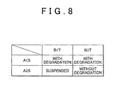
- FIG. 8 is a table summarizing the results of determination obtained when the presence or absence of degradation of the three-way catalyst is determined by the quick determination process in accordance with the embodiment
- FIG. 9A to FIG. 9F are tables showing other examples of the results of the determination of the presence or absence of degradation of the three-way catalyst by the quick determination process in accordance with the embodiment.
- FIG. 10 is a time chart showing changes in the air/fuel ratio of an engine, changes in the output signal of a pre-catalyst sensor, changes in the oxygen storage amount found, and changes in the output signal of a post-catalyst sensor in an active air/fuel ratio control in accordance with the related art.
- a throttle valve 13 is provided in an intake passageway 3 leading to a combustion chamber 2 so that the throttle valve 13 can be opened and closed. Air is taken into the combustion chamber 2 through the intake passageway, and fuel injected from a fuel injection valve 4 is supplied into the combustion chamber 2 via the intake passageway 3 . A mixture of air and fuel supplied into the combustion chamber 2 burns due to ignition by an ignition plug 5 . As the mixture burns within the combustion chamber 2 , a piston 6 reciprocates, rotating a crankshaft 7 that is an output shaft of the engine 1 .
- the mixture After being burned in the combustion chamber 2 , the mixture is sent out as an exhaust gas from the combustion chamber 2 into an exhaust passageway 8 .
- the exhaust gas that passes through the exhaust passageway 8 is let out into the outside after harmful components of the exhaust gas, such as HCs, CO, NOx, etc., are removed by a three-way catalyst of a catalytic converter 16 .
- the three-way catalyst has an oxygen storage function in order to effectively remove the foregoing three components from the exhaust gas.
- the three-way catalyst is equipped with the oxygen storage function, a stoichiometric air/fuel ratio control of controlling the air/fuel ratio of the mixture so that the oxygen concentration in the catalyst atmosphere converges to the value of oxygen concentration occurring at the time of combustion of the mixture at the stoichiometric air/fuel ratio is performed. Therefore, with the three-way catalyst, the three components of exhaust gas, that is, NOx, HCs and CO, can be effectively removed.
- the exhaust passageway 8 upstream of the catalytic converter 16 is provided with an air/fuel ratio sensor 17 as a pre-catalyst sensor that outputs a signal based on the oxygen concentration in exhaust gas
- the passageway downstream of the catalytic converter 16 is provided with an oxygen sensor 18 as a post-catalyst sensor that outputs a signal based on the oxygen concentration in exhaust gas.
- the air/fuel ratio sensor 17 outputs a linear signal commensurate with the oxygen concentration in exhaust gas upstream of the catalyst. That is, the output signal VAF of the air/fuel ratio sensor 17 becomes smaller the lower the oxygen concentration in exhaust gas upstream of the catalyst.
- the value of the output signal VAF becomes, for example, 0 (A), corresponding to the oxygen concentration X in exhaust gas at that time.
- the value of the output signal VAF of the air/fuel ratio sensor 17 becomes smaller below the value 0 (A).
- the value of the output signal VAF of the air/fuel ratio sensor 17 becomes larger above the value 0 (A).
- the oxygen sensor 18 outputs a rich signal or a lean signal according to the oxygen concentration in exhaust gas downstream of the catalyst, as shown in FIG. 3 .
- the value, of the output signal VO of the oxygen sensor 18 becomes, for example, 0.5 (v), when the oxygen concentration in exhaust gas downstream of the catalyst is equal to a value of the oxygen concentration (oxygen concentration X) that occurs when the mixture at the stoichiometric air/fuel ratio is burned.
- oxygen concentration in exhaust gas downstream of the catalyst is higher than the oxygen concentration X due to the fuel-lean combustion, the oxygen sensor 18 outputs the lean signal whose value is smaller than 0.5 (v).
- the value of the lean signal sharply decreases with respect to the increasing oxygen concentration in the lower side of the value 0.5 (v) in the vicinity of the oxygen concentration X whereas the decrease of the value of the lean signal with respect to the increasing oxygen concentration is gentle in a region apart from the oxygen concentration X.
- the oxygen sensor 18 When the oxygen concentration in exhaust gas downstream of the catalyst is lower than the oxygen concentration X due to the fuel-rich combustion, the oxygen sensor 18 outputs the rich signal whose value is greater than 0.5 (v).
- the value of the rich signal sharply increases with respect to the decreasing oxygen concentration in the higher side of the value 0.5 (v) in the vicinity of the oxygen concentration X whereas the increase of the value of the rich signal with respect to the decreasing oxygen concentration is gentle in a region apart from the oxygen concentration X.
- This catalyst degradation detection apparatus includes an electronic control unit 21 that executes various controls regarding the engine 1 .
- the electronic control unit 21 includes: a CPU that executes various computation processes involved in the foregoing controls; a ROM that stores programs and data needed for the controls; a RAM that temporarily stores results of computations performed by the CPU, and the like; input/output ports for the inputting/outputting signals between the electronic control unit 21 and an external device; etc.
- the air/fuel ratio sensor 17 and the oxygen sensor 18 as well as various sensors are connected to the input ports of the electronic control unit 21 .
- the foregoing various sensors include: an accelerator pedal position sensor 28 that detects the amount of depression of an accelerator pedal 27 that is depressed by a driver of the motor vehicle (the accelerator depression amount); a throttle position sensor 30 that detects the degree of opening of the throttle valve 13 provided in the intake passageway 3 (the throttle opening degree); an air flow meter 32 that detects the amount of air taken into the combustion chamber 2 through the intake passageway 3 ; an intake air pressure sensor 33 that detects the pressure in the intake passageway 3 at the downstream side of the throttle valve 13 (the intake air pressure); a crank position sensor 34 that outputs a signal that corresponds to the rotation of the crankshaft 7 and that is used for the calculation of the engine rotation speed and the like; etc.
- the electronic control unit 21 grasps the state of operation of the engine 1 , such as the engine rotation speed, the engine load (that is the amount of air taken into the combustion chamber 2 per cycle of the engine 1 ), etc. on the basis of detection signals input from the various sensors.
- the engine rotation speed is found on the basis of the detection signal from the crank position sensor 34 .
- the engine load is calculated from the engine rotation speed, and the amount of air taken into the engine 1 that is found on the basis of the detection signals from the accelerator pedal position sensor 28 , the throttle position sensor 30 , the air flow meter 32 , etc.
- the electronic control unit 21 outputs command signals to the various drive circuits connected to the output port, according to the engine operation states such as the engine load and the engine rotation speed. Thus, a fuel injection amount control, an ignition timing control, an intake air amount control, etc. regarding the engine 1 are executed via the electronic control unit 21 .
- the foregoing stoichiometric air/fuel ratio control for effectively purifying the exhaust gas of the engine 1 by the three-way catalyst of the catalytic converter 16 is realized by adjusting the amount of fuel injection on the basis of the output signal VAF of the air/fuel sensor 17 and the output signal VO of the oxygen sensor 18 .
- the fuel injection amount of the engine 1 is increased or decreased on the basis of the output signal VAF of the air/fuel ratio sensor 17 so that the output signal VAF becomes equal to the value (0 (A) in this embodiment) thereof that occurs when the mixture at the stoichiometric air/fuel ratio is burned in the combustion chamber 2 of the engine 1 .
- the air/fuel ratio of the mixture in the combustion chamber 2 of the engine 1 is controlled so as to converge to the stoichiometric air/fuel ratio while fluctuating between the rich and lean sides of the stoichiometric air/fuel ratio.
- the center of fluctuation of the air/fuel ratio of the engine 1 that fluctuates between the rich and lean sides so as to converge to the stoichiometric air/fuel ratio as described above will deviate from the stoichiometric air/fuel ratio, due to product variations of the air/fuel ratio sensor 17 , or the like.
- the fuel injection amount of the engine 1 is adjusted also according to the signal output by the oxygen sensor 18 so that the center of fluctuation of the air/fuel ratio of the engine 1 that fluctuates between the rich and lean sides due to the adjustment of the fuel injection amount commensurate with the output signal VAF of the air/fuel ratio sensor 17 becomes equal to the stoichiometric air/fuel ratio.
- the determination as to the presence or absence of degradation of the three-way catalyst of the catalytic converter 16 in this embodiment will be outlined.
- the determination as to the presence or absence of degradation of the three-way catalyst is performed by utilizing a phenomenon in which the oxygen storage function of the three-way catalyst declines with degradation of the three-way catalyst. That is, a maximum value of the amount of oxygen stored in the three-way catalyst which is determined by the oxygen storage function of the three-way catalyst (hereinafter, termed the oxygen storage amount) is found. On the basis of the found oxygen storage amount, it is determined whether or not degradation of the three-way catalyst is present.
- an active air/fuel ratio control is performed in which the air/fuel ratio of the mixture in the combustion chamber 2 of the engine 1 is forced to switch between the rich and lean sides at every predetermined timing. If the air/fuel ratio of the engine 1 is switched between the rich and lean sides by the active air/fuel ratio control, a change that corresponds to the switching appears in the output signal VAF of the air/fuel ratio sensor 17 .
- a calculation is performed to find the amount of oxygen that is stored into the three-way catalyst or desorbed from the three-way catalyst during a period from when the foregoing change occurs in the output signal VAF of the air/fuel ratio sensor 17 to when a change that corresponds to the foregoing change in the air/fuel ratio occurs in the output signal VO of the oxygen sensor 18 .
- the foregoing forced change in the air/fuel ratio is performed from the rich side to the lean side
- oxygen is then stored into the three-way catalyst during the foregoing period.
- the amount of oxygen stored into the three-way catalyst during the period is calculated, and the calculated amount of oxygen is determined as the oxygen storage amount of the catalyst.
- oxygen is then desorbed from the three-way catalyst during the period. Then, the amount of oxygen desorbed from the three-way catalyst during the period is calculated, and the calculated amount of oxygen is determined as the oxygen storage amount of the catalyst.
- the oxygen storage amount as an index for determining the presence or absence of degradation of the three-way catalyst may be, for example, at least one of a value that is found by changing the air/fuel ratio from the rich side to the lean side (an oxygen storage amount OSC 1 found at the time of storage of oxygen) and a value that is found by changing the air/fuel ratio from the lean side to the rich side (an oxygen storage amount OSC 2 found at the time of desorption of oxygen). If the oxygen storage amount for the determination regarding the degradation that is found as described above is less than the threshold value, it is conceivable to determine that there has been a decline in the oxygen storage function caused by degradation of the three-way catalyst, and therefore to determine that degradation of the three-way catalyst is present.
- the foregoing oxygen storage amount is greater than or equal to the threshold value, it is conceivable to determine that there has not been a decline in the oxygen storage amount caused by degradation of the three-way catalyst, and therefore to determine that the three-way catalyst has not degraded (is normal).
- the determination as to the presence or absence of degradation of the three-way catalyst it is conceivable to perform the determination at least once during the period from a start of operation of the engine 1 till the end of operation thereof. Incidentally, after the determination as to the presence or absence of degradation of the three-way catalyst is completed, the oxygen storage amount found for use for the determination is reset to “0”.
- the active air/fuel ratio control is started on the basis of satisfaction of all of various execution conditions, including a condition that the determination as to the presence or absence of degradation of the three-way catalyst has never been completed following the beginning of the starting of the engine 1 , a condition that the engine 1 is being steadily operated, and a condition that the temperature of the three-way catalyst is in an activation temperature range.
- a timing t 2 in the time chart of the output of the air/fuel ratio sensor in FIG. 4 is a timing at which the output signal VAF of the air/fuel ratio sensor 17 comes to have a value that corresponds to the oxygen concentration in exhaust gas occurring when the mixture at the stoichiometric air/fuel ratio is burned in the combustion chamber 2 of the engine 1 .
- exhaust gas whose oxygen concentration is high passes through the three-way catalyst, corresponding to the change in the air/fuel ratio to the lean side.
- oxygen in exhaust gas is stored into the three-way catalyst. While the storage is being performed, the oxygen concentration in exhaust gas downstream of the catalyst remains low, so that as shown by a solid line in the time chart of the output of the oxygen sensor in FIG. 4 , a change that corresponds to the change in the air/fuel ratio to the lean side does not occur in the output signal VO of the oxygen sensor 18 .
- the total value of the amount of oxygen stored into the three-way catalyst during the period (t 2 to t 3 ) from when a change in the air/fuel ratio from the rich side to the lean side occurs in the output signal VAF of the air/fuel ratio sensor 17 to when a change that corresponds to the change in the air/fuel ratio occurs in the output signal VO of the oxygen sensor 18 is a value that represents the maximum value (oxygen storage amount) of the amount of oxygen stored in the three-way catalyst. This oxygen storage amount is found in the following manner during the period (t 2 to t 3 ).
- the difference ⁇ A/F in the air/fuel ratio represents an absolute value of a value obtained by subtracting the stoichiometric air/fuel ratio from the air/fuel ratio that is found from the output signal VAF of the air/fuel ratio sensor 17 .
- the fuel injection amount Q represents the amount of fuel injection of the engine 1 , that is, the amount of fuel injected from the fuel injection valve 4 , which brings about the air/fuel ratio that is found on the basis of the output signal VAF of the air/fuel ratio sensor 17 .
- the proportion K of oxygen in the expression (1) represents the proportion of oxygen contained in the air.
- the proportion K of oxygen used herein is, for example, a fixed value of “0.23”.
- the oxygen storage amount ⁇ OSC in every infinitesimal time calculated using the expression (1) is integrated over the foregoing period (t 2 to t 3 ). The value obtained by the integration is found as the amount of oxygen stored in the three-way catalyst.
- the value found by the foregoing integration at the end time point of the period (t 2 to t 3 ) is the maximum value of the amount of oxygen that can be stored in the three-way catalyst (oxygen storage amount).
- the thus-found oxygen storage amount is an oxygen storage amount OSC 1 that is found when the three-way catalyst stores oxygen.
- a timing t 6 in the time chart of the output of the air/fuel ratio sensor in FIG. 5 is a timing at which the output signal VAF of the air/fuel ratio sensor 17 comes to have a value that corresponds to the oxygen concentration in exhaust gas that occurs when the mixture at the stoichiometric air/fuel ratio is burned in the combustion chamber 2 of the engine 1 .
- the switching of the air/fuel ratio of the engine 1 from the rich side to the lean side is performed, for example, at the time point when output signal VO of the oxygen sensor 18 reaches the lean-state criterion value HL (the timing t 3 in FIG. 4 ). From the timing t 5 on in FIG. 5 , exhaust gas whose oxygen concentration is low passes through the three-way catalyst, corresponding to the change in the air/fuel ratio to the rich side passes. In this state, oxygen stored in the three-way catalyst is desorbed therefrom and is released into exhaust gas.
- the total value of the amount of oxygen desorbed from the three-way catalyst during the period (t 6 to t 7 ) from when a change in the air/fuel ratio from the lean side to the rich side occurs in the output signal VAF of the air/fuel ratio sensor 17 to when a change that corresponds to the change in the air/fuel ratio occurs in the output signal VO of the oxygen sensor 18 is a value that represents the maximum value (oxygen storage amount) of the amount of oxygen stored in the three-way catalyst.
- This oxygen storage amount is found during the foregoing period (t 6 to t 7 ) by using substantially the same technique as used during the period (t 2 to t 3 ) shown in FIG. 4 .
- an oxygen storage amount ⁇ OSC is calculated as the amount of oxygen stored into the three-way catalyst in every infinitesimal time, by using the foregoing expression (1). Then, the oxygen storage amount ⁇ OSC in every infinitesimal time calculated using the expression (1) is integrated over the foregoing period (t 6 to t 7 ). The value obtained by the integration is found as the amount of oxygen desorbed from the three-way catalyst. Therefore, the value found by the foregoing integration at the end time point of the period (t 6 to t 7 ) is the maximum value (oxygen storage amount) of the amount of oxygen that can be stored in the three-way catalyst. The thus-found oxygen storage amount is an oxygen storage amount OSC 2 that is found when oxygen is desorbed from the three-way catalyst.
- the active/air/fuel ratio control is ended after the oxygen storage needed for determining the presence or absence of degradation of the three-way catalyst is found. That is, in the case where the oxygen storage amount needed for determining the presence or absence of degradation of the three-way catalyst is one of the oxygen storage amount OSC 1 and the oxygen storage amount OSC 2 , the active air/fuel ratio control is ended after that the oxygen storage amount is found. In the case where the oxygen storage amount needed for determining the presence or absence of degradation of the three-way catalyst is each one of the oxygen storage amount OSC 1 and the oxygen storage amount OSC 2 , the active air/fuel ratio control is ended after the oxygen storage amounts OSC 1 and OSC 2 are found.
- the oxygen storage amount found as described above sometimes deviates from a proper value because of being affected by deterioration of the responsiveness of the change in the output signal VO of the oxygen sensor 18 to a change in the oxygen concentration in exhaust gas downstream of the catalyst.
- the period for which the oxygen storage amount is calculated increases from a period from t 2 to t 3 to a period from t 2 to t 4 .
- the oxygen storage amount OSC 1 found at the end time point of the period from t 2 to t 4 is a value (value at the timing t 4 ) that is excessively larger than a proper value (value at the timing t 3 ), as shown by the two-dot chain line in the time chart of the oxygen storage amount in FIG. 4 .
- the deterioration of the responsiveness of the oxygen sensor 18 appears in the output signal VO of the oxygen sensor 18 in the form of a change from the transition shown by a solid line in the time chart of the output of the oxygen sensor in FIG.
- the period for which the oxygen storage amount is calculated increases from a period from t 6 to t 7 to a period from t 6 to t 8 .
- the oxygen storage amount OSC 2 found at the end time point of the period (t 6 to t 8 ) is a value (value at the timing t 8 ) that is excessively larger than a proper value (value at the timing t 7 ), as shown by a two-dot chain line in the time chart of the oxygen storage amount in FIG. 5 .
- an error may sometimes occur in the determination.
- the responsiveness of the change in the output signal VO of the oxygen sensor 18 to a change in the oxygen concentration in exhaust gas downstream of the catalyst is measured. Then, the oxygen storage amount for use for determining the presence or absence of degradation of the three-way catalyst is directly corrected by reduction so that the oxygen storage amount is reduced more greatly the more deteriorated the measured responsiveness is relative to a reference value. Due to this, the post-correction oxygen storage amount for use for determining the presence or absence of degradation of the three-way catalyst is restrained from deviating from a proper value due to deterioration of the responsiveness of the oxygen sensor 18 .
- the measurement of the responsiveness of the oxygen sensor 18 it is conceivable to perform the measurement as follows. That is, when the air/fuel ratio of the engine 1 changes between the rich side and the lean side a change that corresponds to such change in the air/fuel ratio occurs in the output signal VO of the oxygen sensor 18 , a response time from when the output signal VO starts changing to when the output signal VO reaches the lean-state criterion value HL or the rich-state criterion value HR is measured as a value that corresponds to the foregoing responsiveness. The response time measured in this manner becomes greater in value as the responsiveness of the oxygen sensor 18 deteriorates.
- the effect of deterioration of the responsiveness of the oxygen sensor 18 on the output signal VO does not necessarily appear in manners as shown by the two-dot chain line L 1 in the time chart of the output of the oxygen sensor in FIG. 4 or the two-dot chain line L 4 in the time chart of the output of the oxygen sensor in FIG. 5 , but may possibly appear in a manner that is different from those shown by the two-dot chain lines L 1 and L 4 , depending on the state of operation of the engine 1 , or the like.
- the degree of deterioration of the responsiveness of the oxygen sensor 18 is substantially equal to the degree of deterioration shown by the two-dot chain line L 1 in the time chart of the output of the oxygen sensor in FIG.
- the effect of deterioration of the responsiveness of the oxygen sensor 18 may possibly appear in the output signal VO of the oxygen sensor 18 , for example, in a manner as shown by two-dot chain lines L 2 and L 3 , depending on the state of operation of the engine 1 , or the like.
- the effect of deterioration of the responsiveness of the oxygen sensor 18 that appears in the output signal VO of the oxygen sensor 18 may vary as shown by the two-dot chain lines L 2 and L 3 in the time chart of the output of the oxygen sensor in FIG. 4 .
- the effect of deterioration of the responsiveness of the oxygen sensor 18 may possibly appear in the output signal VO of the oxygen sensor 18 , for example, in a manner as shown by two-dot chain lines L 5 and L 6 .
- the effect of deterioration of the responsiveness of the oxygen sensor 18 that appears in the output signal VO of the oxygen sensor 18 may vary as shown by the two-dot chain lines L 5 and L 6 in the time chart of the output of the oxygen sensor in FIG. 5 , depending on the state of operation of the engine 1 , or the like.
- the lean-state criterion value HL or the rich-state criterion value HR is corrected on the basis of deterioration of the responsiveness of the oxygen sensor 18 and therefore the present responsiveness of the oxygen sensor 18 is reflected in the oxygen storage amount OSC 1 or OSC 2 that is found for use for determining the presence or absence of degradation of the three-way catalyst, the following inconveniences occur. That is, when the effect of deterioration of the responsiveness of the oxygen sensor 18 that appears in the output signal VO of the oxygen sensor 18 varies depending on the state of operation of the engine 1 or the like, the oxygen storage amount OSC 1 or OSC 2 reflecting the responsiveness of the oxygen sensor has a value that is deviated from a proper value. Then, since there is possibility that the presence or absence of degradation of the three-way catalyst may be determined on the basis of the oxygen storage amount OSC 1 or OSC 2 deviated from the proper value, it cannot be clearly said that a result of the determination is definitely proper.
- the variation can be prevented from resulting in variation of the post-correction oxygen storage amount that is provided for use for determining the presence or absence of degradation of the three-way catalyst.
- the oxygen storage amount for use for determining the presence or absence of degradation of the three-way catalyst is directly corrected on the basis of the responsiveness of the oxygen sensor 18 .
- the post-correction oxygen storage amount is restrained from being deviated from the proper value. Therefore, by determining the presence or absence of degradation of the three-way catalyst on the basis of the post-correction oxygen storage amount, it is possible to properly determine the presence or absence of degradation of the three-way catalyst irrespective of variations in the effect of deterioration of the responsiveness of the oxygen sensor 18 that appears in the signal of the oxygen sensor 18 .
- This catalyst degradation detection routine is executed via the electronic control unit 21 , for example, periodically by an interrupt generated at every predetermined time.
- a process (S 101 and S 102 ) of measuring the responsiveness of the oxygen sensor 18 , and a process (S 103 and S 104 ) of calculating the oxygen storage amount OSC 1 or OSC 2 are executed.
- each of the oxygen storage amounts OSC 1 an OSC 2 for use for the determination be corrected according to the responsiveness of the oxygen sensor 18 as follows. That is, the oxygen storage amount OSC 1 (the value found at the time of storage of oxygen) is corrected on the basis of the responsiveness of the output signal VO of the oxygen sensor 18 to changes to the lean side, and the oxygen storage amount OSC 2 (the value found at the time of desorption of oxygen) is corrected on the basis of the responsiveness of the output signal VO of the oxygen sensor 18 to changes to the rich side. Then, on the basis of both the oxygen storage amount OSC 1 and the oxygen storage amount OSC 2 corrected in this manner, the presence or absence of degradation of the three-way catalyst is determined. This is more preferable in terms of making the determination accurate.
- the active air/fuel ratio control is executed when an execution condition for the active air/fuel ratio control is satisfied.
- the responsiveness of the oxygen sensor 18 to changes to the lean side is measured when the air/fuel ratio of the engine 1 is forced to switch from the rich side to the lean side
- the responsiveness of the oxygen sensor 18 to changes to the rich side is measured when the air/fuel ratio of the engine 1 is forced to switch from the lean side to the rich side.
- the responsiveness of the oxygen sensor 18 is measured not only at the time of execution of the active air/fuel ratio control but at all possible opportunities, the measurement can be completed during an earlier period.
- Examples of the opportunities other than the time of execution of the active air/fuel ratio control at which the measurement of the responsiveness can be performed include when during the fuel-cut control of the engine 1 , the fuel injection from the fuel injection valve 4 has been stopped and therefore the air/fuel ratio of the engine 1 changes from the rich side to the lean side.
- the stop of the fuel injection in the fuel-cut control is executed more frequently than the active air/fuel ratio control that is executed upon satisfaction of the execution condition for the control.
- the responsiveness of the oxygen sensor 18 to changes to the lean side is measured also when the air/fuel ratio of the engine 1 changes from the rich side to the lean side due to the stop of the fuel injection in the fuel-cut control.
- the process (S 103 and S 104 ) of calculating the oxygen storage amounts OSC 1 and OSC 2 is executed. Specifically, in the process of S 103 , it is determined whether or not both the oxygen storage amounts OSC 1 and OSC 2 have already been calculated. If a negative determination is made in this step, a calculation process (S 104 ) of calculating the oxygen storage amount OSC 1 and/or the oxygen storage amount OSC 2 that has not been calculated is executed.
- the active air/fuel ratio control is executed for the purpose of calculating the oxygen storage amount OSC 1 and/or the oxygen storage amount OSC 2 , when the execution condition for the active air/fuel ratio control is satisfied. Then, during the active air/fuel ratio, control, when the air/fuel ratio of the engine 1 is forced to switch from the rich side to the lean side, the oxygen storage amount OSC 1 is calculated as an oxygen storage amount found when oxygen is stored into the three-way catalyst. Besides, during the active air/fuel ratio control, when the air/fuel ratio of the engine 1 is forced to switch from the lean side to the rich side, the oxygen storage amount OSC 2 is calculated as an oxygen storage amount found when oxygen desorbs from the three-way catalyst.
- the presence or absence of degradation of the three-way catalyst In order to accurately determine the presence or absence of degradation of the three-way catalyst, it is preferable to determine the presence or absence of degradation of the three-way catalyst on the basis of both the oxygen storage amount OSC 1 corrected on the basis of the responsiveness of the oxygen sensor 18 to changes to the lean side and the oxygen storage amount OSC 2 corrected on the basis of the responsiveness of the oxygen sensor 18 to changes to the rich side, as described above.
- this manner of determining the presence or absence of degradation of the three-way catalyst is to be realized, it is inevitable that a long time is required before the determination is completed.
- the frequency of the measurement of one of the two responsivenesses is different from the frequency of the measurement of the other responsiveness. Therefore, there occurs a situation in which one of the responsiveness of the oxygen sensor 18 to changes to the lean side and the responsiveness thereof to changes to the rich side can be measured but the other cannot be measured. Hence, the completion of the responsiveness measurement requires a long time. Incidentally, in this embodiment, occurrence of a situation in which the measurement of the responsiveness of the oxygen sensor 18 to changes to the rich side cannot be completed while the measurement of the responsiveness thereof to changes to the lean side is completed is highly likely.
- the catalyst degradation detection routine is performed as follows. After an affirmative determination is made in the process of S 103 , that is, after it is determined that both the oxygen storage amounts OSC 1 and OSC 2 have already been calculated, a process starting at S 105 in which the presence or absence of degradation of the three-way catalyst is determined so as to promptly complete the determination as to the presence or absence of degradation of the three-way catalyst and also prevent decline in the accuracy of the determination is executed.
- an ordinary determination process of determining the presence or absence of degradation of the three-way catalyst so as to make an accurate determination is executed (S 108 ).
- the oxygen storage amount OSC 1 is corrected on the basis of the responsiveness of the oxygen sensor 18 to changes to the lean side
- the oxygen storage amount OSC 2 is corrected on the basis of the responsiveness of the oxygen sensor 18 to changes to the rich side.
- the post-correction oxygen storage amount OSC 1 is compared with a predetermined threshold value
- the post-correction oxygen storage amount OSC 2 is compared with a predetermined threshold value. If the post-correction oxygen storage amount OSC 1 is less than the threshold value or the post-correction oxygen storage amount OSC 2 is less than the threshold value, it is determined that degradation of the three-way catalyst is present. Besides, if the post-correction oxygen storage amount OSC 1 is greater than or equal to the threshold value and the post-correction oxygen storage amount OSC 2 is greater than or equal to the threshold value, it is determined that degradation of the three-way catalyst is not present (the three-way catalyst is normal). By determining the presence or absence of degradation of the three-way catalyst in the foregoing manner, accurate results of the determination can be obtained.
- the responsiveness that has already been measured is used as a basis to correct the oxygen storage amount (OSC 1 of OSC 2 ) that corresponds to that responsiveness (S 201 ).
- the oxygen storage amount OSC 1 is corrected on that responsiveness.
- the oxygen storage amount that has been corrected in the process of S 201 is hereinafter termed the post-correction oxygen storage amount A.
- an average value B of the oxygen storage amount that corresponds to the responsiveness that has not yet been measured and the post-correction oxygen storage amount A is calculated (S 202 ).
- the average value B is calculated from the post-correction oxygen storage amount OSC 1 (that corresponds to the post-correction oxygen storage amount A) and the oxygen storage amount OSC 2 that has not been corrected on the basis of the responsiveness.
- the presence or absence of degradation of the three-way catalyst is determined (S 203 to S 207 ) on the basis of comparison of the post-correction oxygen storage amount A with a predetermined first threshold value S and comparison of the average value B with a predetermined second threshold value T that is greater than the first threshold value S.
- the post-correction oxygen storage amount A is less than the first threshold value S (S 203 ). If an affirmative determination is made in S 203 , then it is determined that the three-way catalyst has degraded (is abnormal) (S 204 ). On the other hand, if a negative determination is made in S 203 and therefore it is determined that the post-correction oxygen storage amount A is greater than or equal to the first threshold value S, it is then determined whether or not the average value B is less than the second threshold value T (S 205 ). If a negative determination is made in this step, it is determined that the three-way catalyst has not been degraded (is normal) (S 207 ).
- the presence or absence of degradation of the three-way catalyst can be determined if only one of the responsiveness of the oxygen sensor 18 to changes to the lean side and the responsiveness thereof to changes to the rich side has been measured. Therefore, the determination can be completed promptly and early.
- the determination as to the presence or absence of degradation of the three-way catalyst is performed not only on the basis of the oxygen storage amount corrected on the basis of the responsiveness of the oxygen sensor 18 (post-correction oxygen storage amount A), but also on the basis of the average value B of the post-correction oxygen storage amount A and an oxygen storage amount that corresponds to the unmeasured one of the two types of responsivenesses of the oxygen sensor 18 .
- the determination is performed by taking into account not only the post-correction oxygen storage amount A but also the average value B, the decline in the accuracy of the determination as to the presence or absence of degradation of the three-way catalyst which is caused by the determination based on only the post-correction oxygen storage amount A is restrained.
- the presence or absence of degradation of the three-way catalyst is determined on the basis of the maximum value of the amount of oxygen stored in the three-way catalyst (oxygen storage amount).
- oxygen storage amount is found, and the responsiveness of the change in the output signal VO of the oxygen sensor 18 to a change in the oxygen concentration in exhaust gas downstream of the catalyst is measured.
- the oxygen storage amount for use for determining the presence or absence of degradation of the three-way catalyst is directly corrected by reduction so that the oxygen storage amount is reduced more greatly the more deteriorated the measured responsiveness is relative to a reference value.
- the variation can be restrained from resulting in variation of the post-correction oxygen storage amount for use for determining the presence or absence of degradation of the three-way catalyst.
- the post-correction oxygen storage amount is restrained from becoming deviated from the proper value. Therefore, by determining the presence or absence of degradation of the three-way catalyst on the basis of the post-correction oxygen storage amount, it is possible to properly determine the presence or absence of degradation of the three-way catalyst irrespective of variations in the effect of deterioration of the responsiveness of the oxygen sensor 18 that appears in the signal of the oxygen sensor 18 .
- the quick determination process is carried out so as to complete the determination as to the presence or absence of degradation of the three-way catalyst while achieving a certain degree of accuracy of the determination.
- the presence or absence of degradation of the three-way catalyst can be determined if only one of the responsiveness of the oxygen sensor 18 to changes to the lean side and the responsiveness thereof to changes to the rich side has been measured. Therefore, the determination can be completed promptly and early.
- the presence or absence of degradation of the three-way catalyst is determined by taking into account not only the post-correction oxygen storage amount A but also the average value B, the decline in the accuracy of the determination as to the presence or absence of degradation of the three-way catalyst which is caused by the determination based on only the post-correction oxygen storage amount A is restrained.
- the embodiment reduces the incidence of a situation in which although the three-way catalyst has actually degraded, it is not determined that degradation of the three-way catalyst is present.
- the condition that the post-correction oxygen storage amount A is greater than or equal to the first threshold value S and the average value B is greater than or equal to the second threshold value T means a situation in which it is very highly likely that the three-way catalyst is normal. When the possibility of the three-way catalyst being normal is high, it is determined that degradation of the three-way catalyst is not present. Therefore, when it is determined that degradation of the three-way catalyst is not present, the determination can be provided as an accurate one.
- a fifth effect will be described.
- the situation in which the post-correction oxygen storage amount A is greater than or equal to the first threshold value S and the average value B is less than the second threshold value T means a situation in which it is difficult to determine whether the three-way catalyst has degraded, or has not degraded but is normal.
- the embodiment is able to avoid an error in the determination as to the presence or absence of degradation of the three-way catalyst which can be caused when the determination is performed easily without careful consideration.
- the foregoing embodiments can be changed, for example, as follows.
- the determination as to the presence or absence of degradation of the three-way catalyst may be performed so that results of the determination based on the comparison of the post-correction oxygen storage amount A with the first threshold value S and the comparison of the average value B with the second threshold value T are as shown tables in FIGS. 9A to 9F .
- the oxygen sensor 18 as a post-catalyst sensor, may be substituted with an air/fuel ratio sensor.
- the air/fuel ratio sensor 17 as a pre-catalyst sensor, may be substituted with an oxygen sensor.
Abstract
Description
ΔOSC=(ΔA/F)·Q·K (1)
ΔOSC: oxygen storage amount in every infinitesimal time
ΔA/F: difference in the air/fuel ratio
Q: fuel injection amount
K: proportion of oxygen
In the expression (1), the difference ΔA/F in the air/fuel ratio represents an absolute value of a value obtained by subtracting the stoichiometric air/fuel ratio from the air/fuel ratio that is found from the output signal VAF of the air/
Claims (6)
Applications Claiming Priority (3)
| Application Number | Priority Date | Filing Date | Title |
|---|---|---|---|
| JP2010-051855 | 2010-03-09 | ||
| JP2010051855A JP5024405B2 (en) | 2010-03-09 | 2010-03-09 | Catalyst degradation detector |
| PCT/IB2011/000367 WO2011110912A1 (en) | 2010-03-09 | 2011-02-24 | Catalyst degradation detection apparatus |
Publications (2)
| Publication Number | Publication Date |
|---|---|
| US20120324869A1 US20120324869A1 (en) | 2012-12-27 |
| US8938947B2 true US8938947B2 (en) | 2015-01-27 |
Family
ID=44146925
Family Applications (1)
| Application Number | Title | Priority Date | Filing Date |
|---|---|---|---|
| US13/583,139 Active 2031-10-30 US8938947B2 (en) | 2010-03-09 | 2011-02-24 | Catalyst degradation detection apparatus |
Country Status (4)
| Country | Link |
|---|---|
| US (1) | US8938947B2 (en) |
| JP (1) | JP5024405B2 (en) |
| CN (1) | CN102791982B (en) |
| WO (1) | WO2011110912A1 (en) |
Cited By (3)
| Publication number | Priority date | Publication date | Assignee | Title |
|---|---|---|---|---|
| US20130006506A1 (en) * | 2011-06-29 | 2013-01-03 | Toyota Jidosha Kabushiki Kaisha | Control apparatus for internal combustion engine |
| US20140208718A1 (en) * | 2013-01-25 | 2014-07-31 | Robert Bosch Gmbh | Method and device for determining the oxygen storage capacity of an emission control system |
| US20240044276A1 (en) * | 2021-02-05 | 2024-02-08 | Yamaha Hatsudoki Kabushiki Kaisha | Straddled vehicle |
Families Citing this family (14)
| Publication number | Priority date | Publication date | Assignee | Title |
|---|---|---|---|---|
| JP5062307B2 (en) | 2010-08-06 | 2012-10-31 | トヨタ自動車株式会社 | Catalyst degradation detector |
| US9599006B2 (en) | 2011-08-30 | 2017-03-21 | GM Global Technology Operations LLC | Catalyst oxygen storage capacity adjustment systems and methods |
| WO2013061394A1 (en) * | 2011-10-24 | 2013-05-02 | トヨタ自動車株式会社 | Catalyst-degradation detection device |
| US9897028B2 (en) | 2013-06-26 | 2018-02-20 | Toyota Jidosha Kabushiki Kaisha | Diagnosis system of internal combustion engine |
| JP6156310B2 (en) * | 2014-09-26 | 2017-07-05 | トヨタ自動車株式会社 | Control device for internal combustion engine |
| JP6287939B2 (en) * | 2015-04-13 | 2018-03-07 | トヨタ自動車株式会社 | Exhaust gas purification device for internal combustion engine |
| US9650981B1 (en) | 2015-12-28 | 2017-05-16 | GM Global Technology Operations LLC | Adjustment of measured oxygen storage capacity based on upstream O2 sensor performance |
| JP6658672B2 (en) * | 2017-05-26 | 2020-03-04 | 株式会社デンソー | Gas sensor control device |
| CN109519264B (en) * | 2018-11-06 | 2020-12-25 | 马瑞利(中国)有限公司 | Gasoline engine three-way catalyst diagnosis rapid diagnosis method and system |
| CN111721890A (en) * | 2020-05-09 | 2020-09-29 | 北京雪迪龙科技股份有限公司 | Automatic quality detection method for adsorbent or catalyst and application thereof |
| CN112267929B (en) * | 2020-10-16 | 2022-01-21 | 潍柴动力股份有限公司 | Method for saving precious metal consumption of three-way catalyst, tail gas treatment system and vehicle |
| JP7351318B2 (en) * | 2021-02-12 | 2023-09-27 | トヨタ自動車株式会社 | Internal combustion engine control device |
| CN114704362A (en) * | 2021-04-26 | 2022-07-05 | 长城汽车股份有限公司 | Lean-burn NOx trap fault detection method, device, vehicle, medium and equipment |
| CN114810391A (en) * | 2022-04-29 | 2022-07-29 | 广西玉柴机器股份有限公司 | Control strategy for implementing oxygen storage compensation of degradation catalyst |
Citations (91)
| Publication number | Priority date | Publication date | Assignee | Title |
|---|---|---|---|---|
| US4739614A (en) * | 1985-02-22 | 1988-04-26 | Toyota Jidosha Kabushiki Kaisha | Double air-fuel ratio sensor system in internal combustion engine |
| US4745741A (en) * | 1985-04-04 | 1988-05-24 | Toyota Jidosha Kabushiki Kaisha | Double air-fuel ratio sensor system having improved response characteristics |
| US4817384A (en) * | 1986-08-13 | 1989-04-04 | Toyota Jidosha Kabushiki Kaisha | Double air-fuel ratio sensor system having improved exhaust emission characteristics |
| US5088281A (en) * | 1988-07-20 | 1992-02-18 | Toyota Jidosha Kabushiki Kaisha | Method and apparatus for determining deterioration of three-way catalysts in double air-fuel ratio sensor system |
| US5097700A (en) * | 1990-02-27 | 1992-03-24 | Nippondenso Co., Ltd. | Apparatus for judging catalyst of catalytic converter in internal combustion engine |
| US5191762A (en) * | 1990-05-30 | 1993-03-09 | Honda Giken Kogyo K.K. | System for detecting deterioration of a three-way catalyst of an internal combustion engine |
| US5207057A (en) * | 1991-05-16 | 1993-05-04 | Toyota Jidosha Kabushiki Kaisha | Air-fuel ratio control device for an engine |
| JPH05256175A (en) | 1992-03-16 | 1993-10-05 | Mazda Motor Corp | Exhaust sensor degradation detecting device for engine |
| US5279116A (en) * | 1991-12-16 | 1994-01-18 | Toyota Jidosha Kabushiki Kaisha | Device for determining deterioration of a catalytic converter for an engine |
| US5282383A (en) * | 1991-04-23 | 1994-02-01 | Toyota Jidosha Kabushiki Kaisha | Method and apparatus for determining deterioration of three-way catalysts in double air-fuel ratio sensors system |
| US5325664A (en) * | 1991-10-18 | 1994-07-05 | Honda Giken Kogyo Kabushiki Kaisha | System for determining deterioration of catalysts of internal combustion engines |
| US5337558A (en) | 1992-03-16 | 1994-08-16 | Mazda Motor Corporation | Engine exhaust purification system |
| US5359853A (en) * | 1992-12-09 | 1994-11-01 | Toyota Jidosha Kabushiki Kaisha | Device for detecting deterioration of a catalytic converter for an engine |
| US5444977A (en) * | 1992-11-02 | 1995-08-29 | Nippondenso Co., Ltd. | Air/fuel ratio sensor abnormality detecting device for internal combustion engine |
| US5475975A (en) * | 1993-09-21 | 1995-12-19 | Toyota Jidosha Kabushiki Kaisha | Air-fuel ratio control device for an engine |
| JPH08100635A (en) | 1994-09-30 | 1996-04-16 | Mitsubishi Motors Corp | Catalyst deterioration detection device for internal combustion engine |
| US5533332A (en) * | 1993-09-02 | 1996-07-09 | Unisia Jecs Corporation | Method and apparatus for self diagnosis of an internal combustion engine |
| JPH08220051A (en) * | 1995-02-10 | 1996-08-30 | Mitsubishi Motors Corp | Device for diagnosing deterioration of air-fuel ratio sensor |
| US5727383A (en) * | 1995-02-10 | 1998-03-17 | Nippondenso Co., Ltd. | Catalyst deterioration detecting apparatus and exhaust emission control device failure detecting apparatus |
| US5732552A (en) * | 1995-02-10 | 1998-03-31 | Mitsubishi Jidosha Kogyo Kabushiki Kaisha | Apparatus for deterioration diagnosis of an exhaust purifying catalyst |
| US5732553A (en) * | 1995-04-20 | 1998-03-31 | Toyota Jidosha Kabushiki Kaisha | Device for determining deterioration of a catalytic converter for an engine |
| US5735120A (en) * | 1995-11-21 | 1998-04-07 | Toyota Jidosha Kabushiki Kaisha | Device for judging the deterioration of a catalyst of an engine |
| US5737917A (en) * | 1995-12-07 | 1998-04-14 | Toyota Jidosha Kabushiki Kaisha | Device for judging deterioration of catalyst of engine |
| US5743082A (en) | 1994-09-30 | 1998-04-28 | Mitsubishi Jidosha Kogyo Kabushiki Kaisha | Apparatus for detecting reduction of purifying capacity of catalyst for purifying exhaust gas from internal combustion engine and method thereof |
| US5743086A (en) * | 1995-10-26 | 1998-04-28 | Toyota Jidosha Kabushiki Kaisha | Device for judging deterioration of catalyst of engine |
| US5806306A (en) * | 1995-06-14 | 1998-09-15 | Nippondenso Co., Ltd. | Deterioration monitoring apparatus for an exhaust system of an internal combustion engine |
| US5875628A (en) * | 1996-02-28 | 1999-03-02 | Toyota Jidosha Kabushiki Kaisha | Air-fuel ratio control apparatus for internal combustion engine |
| US5877413A (en) * | 1998-05-28 | 1999-03-02 | Ford Global Technologies, Inc. | Sensor calibration for catalyst deterioration detection |
| US6050128A (en) * | 1998-05-28 | 2000-04-18 | Ford Global Technologies, Inc. | Catalyst deterioration monitoring |
| US6116021A (en) * | 1997-02-26 | 2000-09-12 | Motorola, Inc. | Method for monitoring the performance of a catalytic converter using a rate modifier |
| US6131439A (en) * | 1998-05-28 | 2000-10-17 | Ford Global Technologies, Inc. | Catalyst deterioration detection with sensor calibration |
| US20010015066A1 (en) * | 2000-02-23 | 2001-08-23 | Hitachi, Ltd. | Engine exhaust gas cleaning system |
| JP2001227384A (en) | 2000-02-16 | 2001-08-24 | Nissan Motor Co Ltd | Exhaust emission control device for engine |
| US20010025485A1 (en) * | 2000-02-23 | 2001-10-04 | Hideaki Kobayashi | Air-fuel ratio control of engine |
| US20010028868A1 (en) * | 2000-04-10 | 2001-10-11 | Honda Giken Kogyo Kabushiki Kaisha | Exhaust emission control system for internal combustion engine |
| US6301880B1 (en) * | 2000-01-20 | 2001-10-16 | Ford Global Technologies, Inc. | Method and system for controlling air/fuel level for internal combustion engine with two exhaust banks |
| US6324893B1 (en) * | 1998-12-24 | 2001-12-04 | Toyota Jidosha Kabushiki Kaisha | Diagnostic apparatus and method for adsorbent |
| US6338243B1 (en) * | 1999-09-01 | 2002-01-15 | Honda Giken Kogyo Kabushiki Kaisha | Exhaust emission control system for internal combustion engine |
| US20020011068A1 (en) * | 2000-06-26 | 2002-01-31 | Toyota Jidosha Kabushiki Kaisha | Air-fuel ratio control apparatus of internal combustion engine |
| US6354077B1 (en) * | 2000-01-20 | 2002-03-12 | Ford Global Technologies, Inc. | Method and system for controlling air/fuel level in two-bank exhaust system |
| US20020029562A1 (en) * | 1999-06-18 | 2002-03-14 | Hitachi, Ltd. | Engine exhaust purifying apparatus |
| US6383267B1 (en) * | 1999-06-10 | 2002-05-07 | Hitachi, Ltd. | Exhaust gas cleaning system for an engine |
| JP2002130018A (en) | 2000-10-26 | 2002-05-09 | Mitsubishi Motors Corp | Exhaust emission control system |
| US20020161495A1 (en) * | 2001-04-25 | 2002-10-31 | Masahito Yamaki | Vehicle control system |
| US20020173919A1 (en) * | 2001-05-18 | 2002-11-21 | Honda Giken Kogyo Kabushiki Kaisha | Exhaust emission control system for internal combustion engine |
| US20020173901A1 (en) * | 2001-04-20 | 2002-11-21 | Unisia Jecs Corporation | Control apparatus and control method |
| US20030005746A1 (en) * | 2001-07-04 | 2003-01-09 | Toyota Jidosha Kabushiki Kaisha | Abnormality diagnosis system and method for oxygen sensor |
| US20030019485A1 (en) | 2001-07-27 | 2003-01-30 | Nissan Motor Co., Ltd. | Air/fuel ratio controller for internal combustion engine |
| US20030041591A1 (en) * | 2001-08-28 | 2003-03-06 | Shigetaka Kuroda | Exhaust gas purifying apparatus for an internal-combustion engine |
| US20030041592A1 (en) * | 2001-08-28 | 2003-03-06 | Honda Giken Kogyo Kabushiki Kaisha | Exhaust gas purifying apparatus for an internal-combustion engine |
| US20030041590A1 (en) * | 2001-08-28 | 2003-03-06 | Honda Giken Kogyo Kabushiki Kaisha | An air-fuel ratio feedback control apparatus |
| US20030097873A1 (en) * | 2001-11-26 | 2003-05-29 | Gopichandra Surnilla | System and method for determining degradation of an exhaust gas sensor in an engine |
| US20030098008A1 (en) * | 2001-11-26 | 2003-05-29 | Gopichandra Surnilla | System and method for monitoring and exhaust gas sensor in an engine |
| US20030140680A1 (en) * | 2001-12-25 | 2003-07-31 | Satoshi Nagashima | Failure diagnostic apparatus and method for air-fuel ratio detecting device |
| US20030159432A1 (en) * | 2002-02-28 | 2003-08-28 | Nissan Motor Co., Ltd. | Diagnosis of deterioration in air/fuel ratio sensor |
| US20040025856A1 (en) * | 2002-08-06 | 2004-02-12 | Hisashi Iida | Apparatus for detecting deterioration of air-fuel ratio sensor |
| US20040040541A1 (en) * | 2002-08-27 | 2004-03-04 | Yuichi Goto | Apparatus and method for controlling air-fuel ratio in direct-injection internal combustion engine |
| US20040134186A1 (en) * | 2003-01-14 | 2004-07-15 | Wenbo Wang | Method and apparatus for monitoring catalyst efficiency and secondary air injection |
| US20040139736A1 (en) * | 2001-03-19 | 2004-07-22 | Hitachi Unisia Automotive, Ltd. | Air-fuel ratio control apparatus of internal combustion engine and method thereof |
| US20040211168A1 (en) * | 2003-04-23 | 2004-10-28 | Honda Motor Co., Ltd. | Deterioration detecting device for oxygen concentration sensor |
| US20040226282A1 (en) * | 2002-06-17 | 2004-11-18 | Toyota Jidosha Kabushiki Kaisha | Abnormality detecting system for oxygen sensor and abnormality detecting method |
| US20050262828A1 (en) * | 2004-05-26 | 2005-12-01 | Hitachi, Ltd. | Diagnostic device and method of engine exhaust purifying system |
| US6976382B2 (en) * | 2002-02-20 | 2005-12-20 | Denso Corporation | Abnormality diagnosing apparatus of exhaust gas sensor |
| US20070051094A1 (en) * | 2005-09-08 | 2007-03-08 | Mitsubishi Jidosha Kogyo Kabushiki Kaisha | HC adsorbing material and device for judging deterioration of the HC adsorbing material |
| US20070113538A1 (en) * | 2005-11-18 | 2007-05-24 | Toyota Jidosha Kabushiki Kaisha | Exhaust gas purifying system and abnormality determining method therefor |
| US7240479B1 (en) * | 2006-04-05 | 2007-07-10 | Mitsubishi Electronic Corporation | Abnormality diagnosis apparatus for internal combustion engine |
| US20070220863A1 (en) | 2006-03-24 | 2007-09-27 | Honda Motor Co., Ltd. | Deterioration detecting apparatus for catalyst |
| US20070220862A1 (en) * | 2006-03-24 | 2007-09-27 | Honda Motor Co., Ltd. | Deterioration detecting apparatus for catalyst |
| US20070227121A1 (en) * | 2006-04-03 | 2007-10-04 | Honda Motor Co., Ltd. | Air-fuel ratio control system for internal combustion engine |
| US20070227123A1 (en) * | 2006-04-03 | 2007-10-04 | Honda Motor Co., Ltd. | Air-fuel Ratio control system for internal combustion engine |
| US20070240403A1 (en) * | 2006-04-18 | 2007-10-18 | Mitsubishi Electric Corporation | Catalyst deterioration diagnosis apparatus and catalyst deterioration diagnosis method for internal combustion engine |
| US20070256406A1 (en) | 2006-05-03 | 2007-11-08 | Ford Global Technologies, Llc | Control and Diagnostic Approach for Emission Control Device |
| US20070298504A1 (en) * | 2006-06-27 | 2007-12-27 | Torsten Wolfgang Mueller | Diesel exhaust treatment system catalyst monitoring |
| US20080028829A1 (en) * | 2004-06-29 | 2008-02-07 | Toyota Jidosha Kabushiki Kaisha | Air Fuel Ratio Sensor Deterioration Determination System for Compression Ignition Internal Combustion Engine |
| JP2008031901A (en) | 2006-07-27 | 2008-02-14 | Toyota Motor Corp | Catalyst degradation detecting apparatus of internal-combustion engine |
| US20080148711A1 (en) * | 2006-12-25 | 2008-06-26 | Mitsubishi Electric Corporation | Air fuel ratio control apparatus for an internal combustion engine |
| US20080184695A1 (en) * | 2007-02-06 | 2008-08-07 | Igor Anilovich | Post catalyst oxygen sensor diagnostic |
| JP2008261254A (en) * | 2007-04-11 | 2008-10-30 | Denso Corp | Control device of internal combustion engine |
| US20080295488A1 (en) * | 2007-06-04 | 2008-12-04 | Mitsubishi Electric Corporation | Air fuel ratio control apparatus for an internal combustion engine |
| US20080302087A1 (en) * | 2007-06-08 | 2008-12-11 | Genslak Robert J | Exhaust system monitoring methods and systems |
| US20090019834A1 (en) * | 2007-07-20 | 2009-01-22 | Toyota Jidosha Kabushiki Kaisha | Catalyst deterioration degree acquiring apparatus in internal combustion engine |
| EP2022968A1 (en) | 2007-08-09 | 2009-02-11 | Nissan Motor Co., Ltd. | Air-fuel ratio control device |
| US20090145110A1 (en) * | 2007-12-06 | 2009-06-11 | Hitachi, Ltd. | Apparatus for diagnosing exhaust gas purifying device |
| US20090150019A1 (en) * | 2007-12-06 | 2009-06-11 | Hitachi, Ltd. | Vehicle diagnostic control apparatus |
| WO2009106973A1 (en) * | 2008-02-28 | 2009-09-03 | Toyota Jidosha Kabushiki Kaisha | Apparatus and method for diagnosing catalyst deterioration |
| US20090248281A1 (en) * | 2005-11-01 | 2009-10-01 | Hitachi, Ltd. | Control Apparatus and Method for Internal Combustion Engine |
| US20090288391A1 (en) * | 2006-06-27 | 2009-11-26 | Keiichiro Aoki | Catalyst deterioration detection device |
| US20090313974A1 (en) * | 2008-06-20 | 2009-12-24 | Honda Motor Co., Ltd. | Catalyst deterioration-determination device and method and engine control unit |
| US20100050602A1 (en) * | 2008-09-04 | 2010-03-04 | Denso Corporation | Deterioration diagnosing apparatus for exhaust gas purifying catalyst |
| US20100242933A1 (en) * | 2009-03-31 | 2010-09-30 | Gm Global Technology Operations, Inc. | Post oxygen sensor performance diagnostic with minimum air flow |
| US20110120095A1 (en) * | 2009-11-20 | 2011-05-26 | Gm Global Technology Operations, Inc. | System and method for monitoring catalyst efficiency and post-catalyst oxygen sensor performance |
Family Cites Families (3)
| Publication number | Priority date | Publication date | Assignee | Title |
|---|---|---|---|---|
| JP2005220901A (en) * | 2004-01-06 | 2005-08-18 | Toyota Motor Corp | Catalyst deterioration state evaluation system for internal combustion engine |
| JP4312668B2 (en) * | 2004-06-24 | 2009-08-12 | 三菱電機株式会社 | Air-fuel ratio control device for internal combustion engine |
| JP2007032357A (en) * | 2005-07-25 | 2007-02-08 | Hitachi Ltd | Catalyst diagnosis device for internal combustion engine and automobile equipped with internal combustion engine including catalyst diagnosis device |
-
2010
- 2010-03-09 JP JP2010051855A patent/JP5024405B2/en not_active Expired - Fee Related
-
2011
- 2011-02-24 WO PCT/IB2011/000367 patent/WO2011110912A1/en active Application Filing
- 2011-02-24 US US13/583,139 patent/US8938947B2/en active Active
- 2011-02-24 CN CN201180013017.5A patent/CN102791982B/en not_active Expired - Fee Related
Patent Citations (97)
| Publication number | Priority date | Publication date | Assignee | Title |
|---|---|---|---|---|
| US4739614A (en) * | 1985-02-22 | 1988-04-26 | Toyota Jidosha Kabushiki Kaisha | Double air-fuel ratio sensor system in internal combustion engine |
| US4745741A (en) * | 1985-04-04 | 1988-05-24 | Toyota Jidosha Kabushiki Kaisha | Double air-fuel ratio sensor system having improved response characteristics |
| US4817384A (en) * | 1986-08-13 | 1989-04-04 | Toyota Jidosha Kabushiki Kaisha | Double air-fuel ratio sensor system having improved exhaust emission characteristics |
| US5088281A (en) * | 1988-07-20 | 1992-02-18 | Toyota Jidosha Kabushiki Kaisha | Method and apparatus for determining deterioration of three-way catalysts in double air-fuel ratio sensor system |
| US5097700A (en) * | 1990-02-27 | 1992-03-24 | Nippondenso Co., Ltd. | Apparatus for judging catalyst of catalytic converter in internal combustion engine |
| US5191762A (en) * | 1990-05-30 | 1993-03-09 | Honda Giken Kogyo K.K. | System for detecting deterioration of a three-way catalyst of an internal combustion engine |
| US5282383A (en) * | 1991-04-23 | 1994-02-01 | Toyota Jidosha Kabushiki Kaisha | Method and apparatus for determining deterioration of three-way catalysts in double air-fuel ratio sensors system |
| US5207057A (en) * | 1991-05-16 | 1993-05-04 | Toyota Jidosha Kabushiki Kaisha | Air-fuel ratio control device for an engine |
| US5325664A (en) * | 1991-10-18 | 1994-07-05 | Honda Giken Kogyo Kabushiki Kaisha | System for determining deterioration of catalysts of internal combustion engines |
| US5279116A (en) * | 1991-12-16 | 1994-01-18 | Toyota Jidosha Kabushiki Kaisha | Device for determining deterioration of a catalytic converter for an engine |
| JPH05256175A (en) | 1992-03-16 | 1993-10-05 | Mazda Motor Corp | Exhaust sensor degradation detecting device for engine |
| US5337558A (en) | 1992-03-16 | 1994-08-16 | Mazda Motor Corporation | Engine exhaust purification system |
| US5444977A (en) * | 1992-11-02 | 1995-08-29 | Nippondenso Co., Ltd. | Air/fuel ratio sensor abnormality detecting device for internal combustion engine |
| US5359853A (en) * | 1992-12-09 | 1994-11-01 | Toyota Jidosha Kabushiki Kaisha | Device for detecting deterioration of a catalytic converter for an engine |
| US5533332A (en) * | 1993-09-02 | 1996-07-09 | Unisia Jecs Corporation | Method and apparatus for self diagnosis of an internal combustion engine |
| US5475975A (en) * | 1993-09-21 | 1995-12-19 | Toyota Jidosha Kabushiki Kaisha | Air-fuel ratio control device for an engine |
| JPH08100635A (en) | 1994-09-30 | 1996-04-16 | Mitsubishi Motors Corp | Catalyst deterioration detection device for internal combustion engine |
| US5743082A (en) | 1994-09-30 | 1998-04-28 | Mitsubishi Jidosha Kogyo Kabushiki Kaisha | Apparatus for detecting reduction of purifying capacity of catalyst for purifying exhaust gas from internal combustion engine and method thereof |
| JPH08220051A (en) * | 1995-02-10 | 1996-08-30 | Mitsubishi Motors Corp | Device for diagnosing deterioration of air-fuel ratio sensor |
| US5727383A (en) * | 1995-02-10 | 1998-03-17 | Nippondenso Co., Ltd. | Catalyst deterioration detecting apparatus and exhaust emission control device failure detecting apparatus |
| US5732552A (en) * | 1995-02-10 | 1998-03-31 | Mitsubishi Jidosha Kogyo Kabushiki Kaisha | Apparatus for deterioration diagnosis of an exhaust purifying catalyst |
| US5732553A (en) * | 1995-04-20 | 1998-03-31 | Toyota Jidosha Kabushiki Kaisha | Device for determining deterioration of a catalytic converter for an engine |
| US5806306A (en) * | 1995-06-14 | 1998-09-15 | Nippondenso Co., Ltd. | Deterioration monitoring apparatus for an exhaust system of an internal combustion engine |
| US5743086A (en) * | 1995-10-26 | 1998-04-28 | Toyota Jidosha Kabushiki Kaisha | Device for judging deterioration of catalyst of engine |
| US5735120A (en) * | 1995-11-21 | 1998-04-07 | Toyota Jidosha Kabushiki Kaisha | Device for judging the deterioration of a catalyst of an engine |
| US5737917A (en) * | 1995-12-07 | 1998-04-14 | Toyota Jidosha Kabushiki Kaisha | Device for judging deterioration of catalyst of engine |
| US5875628A (en) * | 1996-02-28 | 1999-03-02 | Toyota Jidosha Kabushiki Kaisha | Air-fuel ratio control apparatus for internal combustion engine |
| US6116021A (en) * | 1997-02-26 | 2000-09-12 | Motorola, Inc. | Method for monitoring the performance of a catalytic converter using a rate modifier |
| US5877413A (en) * | 1998-05-28 | 1999-03-02 | Ford Global Technologies, Inc. | Sensor calibration for catalyst deterioration detection |
| US6050128A (en) * | 1998-05-28 | 2000-04-18 | Ford Global Technologies, Inc. | Catalyst deterioration monitoring |
| US6131439A (en) * | 1998-05-28 | 2000-10-17 | Ford Global Technologies, Inc. | Catalyst deterioration detection with sensor calibration |
| US6324893B1 (en) * | 1998-12-24 | 2001-12-04 | Toyota Jidosha Kabushiki Kaisha | Diagnostic apparatus and method for adsorbent |
| US6383267B1 (en) * | 1999-06-10 | 2002-05-07 | Hitachi, Ltd. | Exhaust gas cleaning system for an engine |
| US20020184877A1 (en) * | 1999-06-18 | 2002-12-12 | Hitachi, Ltd. | Engine exhaust purifying apparatus |
| US20020029562A1 (en) * | 1999-06-18 | 2002-03-14 | Hitachi, Ltd. | Engine exhaust purifying apparatus |
| US6338243B1 (en) * | 1999-09-01 | 2002-01-15 | Honda Giken Kogyo Kabushiki Kaisha | Exhaust emission control system for internal combustion engine |
| US6301880B1 (en) * | 2000-01-20 | 2001-10-16 | Ford Global Technologies, Inc. | Method and system for controlling air/fuel level for internal combustion engine with two exhaust banks |
| US6354077B1 (en) * | 2000-01-20 | 2002-03-12 | Ford Global Technologies, Inc. | Method and system for controlling air/fuel level in two-bank exhaust system |
| JP2001227384A (en) | 2000-02-16 | 2001-08-24 | Nissan Motor Co Ltd | Exhaust emission control device for engine |
| US20010025485A1 (en) * | 2000-02-23 | 2001-10-04 | Hideaki Kobayashi | Air-fuel ratio control of engine |
| US20010015066A1 (en) * | 2000-02-23 | 2001-08-23 | Hitachi, Ltd. | Engine exhaust gas cleaning system |
| US20010028868A1 (en) * | 2000-04-10 | 2001-10-11 | Honda Giken Kogyo Kabushiki Kaisha | Exhaust emission control system for internal combustion engine |
| US20020011068A1 (en) * | 2000-06-26 | 2002-01-31 | Toyota Jidosha Kabushiki Kaisha | Air-fuel ratio control apparatus of internal combustion engine |
| JP2002130018A (en) | 2000-10-26 | 2002-05-09 | Mitsubishi Motors Corp | Exhaust emission control system |
| US20040139736A1 (en) * | 2001-03-19 | 2004-07-22 | Hitachi Unisia Automotive, Ltd. | Air-fuel ratio control apparatus of internal combustion engine and method thereof |
| US20020173901A1 (en) * | 2001-04-20 | 2002-11-21 | Unisia Jecs Corporation | Control apparatus and control method |
| US20020161495A1 (en) * | 2001-04-25 | 2002-10-31 | Masahito Yamaki | Vehicle control system |
| US20020173919A1 (en) * | 2001-05-18 | 2002-11-21 | Honda Giken Kogyo Kabushiki Kaisha | Exhaust emission control system for internal combustion engine |
| US20030005746A1 (en) * | 2001-07-04 | 2003-01-09 | Toyota Jidosha Kabushiki Kaisha | Abnormality diagnosis system and method for oxygen sensor |
| US20030019485A1 (en) | 2001-07-27 | 2003-01-30 | Nissan Motor Co., Ltd. | Air/fuel ratio controller for internal combustion engine |
| US20030041591A1 (en) * | 2001-08-28 | 2003-03-06 | Shigetaka Kuroda | Exhaust gas purifying apparatus for an internal-combustion engine |
| US20030041590A1 (en) * | 2001-08-28 | 2003-03-06 | Honda Giken Kogyo Kabushiki Kaisha | An air-fuel ratio feedback control apparatus |
| US20030041592A1 (en) * | 2001-08-28 | 2003-03-06 | Honda Giken Kogyo Kabushiki Kaisha | Exhaust gas purifying apparatus for an internal-combustion engine |
| US20030098008A1 (en) * | 2001-11-26 | 2003-05-29 | Gopichandra Surnilla | System and method for monitoring and exhaust gas sensor in an engine |
| US20030097873A1 (en) * | 2001-11-26 | 2003-05-29 | Gopichandra Surnilla | System and method for determining degradation of an exhaust gas sensor in an engine |
| US20030140680A1 (en) * | 2001-12-25 | 2003-07-31 | Satoshi Nagashima | Failure diagnostic apparatus and method for air-fuel ratio detecting device |
| US6976382B2 (en) * | 2002-02-20 | 2005-12-20 | Denso Corporation | Abnormality diagnosing apparatus of exhaust gas sensor |
| US20030159432A1 (en) * | 2002-02-28 | 2003-08-28 | Nissan Motor Co., Ltd. | Diagnosis of deterioration in air/fuel ratio sensor |
| US20040226282A1 (en) * | 2002-06-17 | 2004-11-18 | Toyota Jidosha Kabushiki Kaisha | Abnormality detecting system for oxygen sensor and abnormality detecting method |
| US20040025856A1 (en) * | 2002-08-06 | 2004-02-12 | Hisashi Iida | Apparatus for detecting deterioration of air-fuel ratio sensor |
| US20040040541A1 (en) * | 2002-08-27 | 2004-03-04 | Yuichi Goto | Apparatus and method for controlling air-fuel ratio in direct-injection internal combustion engine |
| US20040134186A1 (en) * | 2003-01-14 | 2004-07-15 | Wenbo Wang | Method and apparatus for monitoring catalyst efficiency and secondary air injection |
| US20040211168A1 (en) * | 2003-04-23 | 2004-10-28 | Honda Motor Co., Ltd. | Deterioration detecting device for oxygen concentration sensor |
| US20050262828A1 (en) * | 2004-05-26 | 2005-12-01 | Hitachi, Ltd. | Diagnostic device and method of engine exhaust purifying system |
| US20080028828A1 (en) * | 2004-05-26 | 2008-02-07 | Hitachi, Ltd. | Diagnostic device and method of engine exhaust purifying system |
| US20080028829A1 (en) * | 2004-06-29 | 2008-02-07 | Toyota Jidosha Kabushiki Kaisha | Air Fuel Ratio Sensor Deterioration Determination System for Compression Ignition Internal Combustion Engine |
| US20070051094A1 (en) * | 2005-09-08 | 2007-03-08 | Mitsubishi Jidosha Kogyo Kabushiki Kaisha | HC adsorbing material and device for judging deterioration of the HC adsorbing material |
| US20090266054A1 (en) * | 2005-11-01 | 2009-10-29 | Hitachi, Ltd. | Control Apparatus and Method for Internal Combustion Engine |
| US20090248281A1 (en) * | 2005-11-01 | 2009-10-01 | Hitachi, Ltd. | Control Apparatus and Method for Internal Combustion Engine |
| US20070113538A1 (en) * | 2005-11-18 | 2007-05-24 | Toyota Jidosha Kabushiki Kaisha | Exhaust gas purifying system and abnormality determining method therefor |
| US20070220863A1 (en) | 2006-03-24 | 2007-09-27 | Honda Motor Co., Ltd. | Deterioration detecting apparatus for catalyst |
| US20070220862A1 (en) * | 2006-03-24 | 2007-09-27 | Honda Motor Co., Ltd. | Deterioration detecting apparatus for catalyst |
| JP2007255336A (en) | 2006-03-24 | 2007-10-04 | Honda Motor Co Ltd | Catalyst degradation-detecting device |
| US20070227121A1 (en) * | 2006-04-03 | 2007-10-04 | Honda Motor Co., Ltd. | Air-fuel ratio control system for internal combustion engine |
| US20070227123A1 (en) * | 2006-04-03 | 2007-10-04 | Honda Motor Co., Ltd. | Air-fuel Ratio control system for internal combustion engine |
| US7240479B1 (en) * | 2006-04-05 | 2007-07-10 | Mitsubishi Electronic Corporation | Abnormality diagnosis apparatus for internal combustion engine |
| US20070240403A1 (en) * | 2006-04-18 | 2007-10-18 | Mitsubishi Electric Corporation | Catalyst deterioration diagnosis apparatus and catalyst deterioration diagnosis method for internal combustion engine |
| US20070256406A1 (en) | 2006-05-03 | 2007-11-08 | Ford Global Technologies, Llc | Control and Diagnostic Approach for Emission Control Device |
| US20070298504A1 (en) * | 2006-06-27 | 2007-12-27 | Torsten Wolfgang Mueller | Diesel exhaust treatment system catalyst monitoring |
| US20090288391A1 (en) * | 2006-06-27 | 2009-11-26 | Keiichiro Aoki | Catalyst deterioration detection device |
| JP2008031901A (en) | 2006-07-27 | 2008-02-14 | Toyota Motor Corp | Catalyst degradation detecting apparatus of internal-combustion engine |
| US20080148711A1 (en) * | 2006-12-25 | 2008-06-26 | Mitsubishi Electric Corporation | Air fuel ratio control apparatus for an internal combustion engine |
| US20080184695A1 (en) * | 2007-02-06 | 2008-08-07 | Igor Anilovich | Post catalyst oxygen sensor diagnostic |
| JP2008261254A (en) * | 2007-04-11 | 2008-10-30 | Denso Corp | Control device of internal combustion engine |
| US20080295488A1 (en) * | 2007-06-04 | 2008-12-04 | Mitsubishi Electric Corporation | Air fuel ratio control apparatus for an internal combustion engine |
| US20080302087A1 (en) * | 2007-06-08 | 2008-12-11 | Genslak Robert J | Exhaust system monitoring methods and systems |
| US20090019834A1 (en) * | 2007-07-20 | 2009-01-22 | Toyota Jidosha Kabushiki Kaisha | Catalyst deterioration degree acquiring apparatus in internal combustion engine |
| EP2022968A1 (en) | 2007-08-09 | 2009-02-11 | Nissan Motor Co., Ltd. | Air-fuel ratio control device |
| US20090150019A1 (en) * | 2007-12-06 | 2009-06-11 | Hitachi, Ltd. | Vehicle diagnostic control apparatus |
| US20090145110A1 (en) * | 2007-12-06 | 2009-06-11 | Hitachi, Ltd. | Apparatus for diagnosing exhaust gas purifying device |
| WO2009106973A1 (en) * | 2008-02-28 | 2009-09-03 | Toyota Jidosha Kabushiki Kaisha | Apparatus and method for diagnosing catalyst deterioration |
| JP2009203940A (en) | 2008-02-28 | 2009-09-10 | Toyota Motor Corp | Device and method for diagnosing deterioration in catalyst |
| US20100307135A1 (en) * | 2008-02-28 | 2010-12-09 | Toyota Jidosha Kabushiki Kaisha | Apparatus and method for diagnosing catalyst deterioration |
| US20090313974A1 (en) * | 2008-06-20 | 2009-12-24 | Honda Motor Co., Ltd. | Catalyst deterioration-determination device and method and engine control unit |
| US20100050602A1 (en) * | 2008-09-04 | 2010-03-04 | Denso Corporation | Deterioration diagnosing apparatus for exhaust gas purifying catalyst |
| US20100242933A1 (en) * | 2009-03-31 | 2010-09-30 | Gm Global Technology Operations, Inc. | Post oxygen sensor performance diagnostic with minimum air flow |
| US20110120095A1 (en) * | 2009-11-20 | 2011-05-26 | Gm Global Technology Operations, Inc. | System and method for monitoring catalyst efficiency and post-catalyst oxygen sensor performance |
Non-Patent Citations (2)
| Title |
|---|
| International Search Report issued in International Application No. PCT/IB2011/000367 dated Jun. 29, 2011. |
| Written Opinion of the International Searching Authority issued in International Patent Application No. PCT/IB2011/000367 dated Jun. 29, 2011. |
Cited By (5)
| Publication number | Priority date | Publication date | Assignee | Title |
|---|---|---|---|---|
| US20130006506A1 (en) * | 2011-06-29 | 2013-01-03 | Toyota Jidosha Kabushiki Kaisha | Control apparatus for internal combustion engine |
| US9328681B2 (en) * | 2011-06-29 | 2016-05-03 | Toyota Jidosha Kabushiki Kaisha | Control apparatus for internal combustion engine |
| US20140208718A1 (en) * | 2013-01-25 | 2014-07-31 | Robert Bosch Gmbh | Method and device for determining the oxygen storage capacity of an emission control system |
| US9309799B2 (en) * | 2013-01-25 | 2016-04-12 | Robert Bosch Gmbh | Method and device for determining the oxygen storage capacity of an emission control system |
| US20240044276A1 (en) * | 2021-02-05 | 2024-02-08 | Yamaha Hatsudoki Kabushiki Kaisha | Straddled vehicle |
Also Published As
| Publication number | Publication date |
|---|---|
| CN102791982A (en) | 2012-11-21 |
| JP5024405B2 (en) | 2012-09-12 |
| US20120324869A1 (en) | 2012-12-27 |
| CN102791982B (en) | 2015-05-06 |
| WO2011110912A1 (en) | 2011-09-15 |
| WO2011110912A8 (en) | 2011-11-24 |
| JP2011185172A (en) | 2011-09-22 |
Similar Documents
| Publication | Publication Date | Title |
|---|---|---|
| US8938947B2 (en) | Catalyst degradation detection apparatus | |
| US8899015B2 (en) | Catalyst degradation detection device | |
| US8234916B2 (en) | Abnormality diagnosis device for air-fuel ratio sensor | |
| US8522531B2 (en) | Catalyst degradation detection apparatus and catalyst degradation detection method | |
| US7520274B2 (en) | Air fuel ratio sensor deterioration determination system for compression ignition internal combustion engine | |
| JP6256240B2 (en) | Control device for internal combustion engine | |
| US7513105B2 (en) | Exhaust gas purifying system and abnormality determining method therefor | |
| US10161329B2 (en) | Upstream NOx estimation | |
| JP3868693B2 (en) | Air-fuel ratio control device for internal combustion engine | |
| US9291085B2 (en) | Device and method for estimating ideal air-fuel ratio in internal combustion engine, method of estimating oxygen storage capacity of catalyst, internal combustion engine device and motorcycle incorporating internal combustion engine device | |
| JP5515967B2 (en) | Diagnostic equipment | |
| JP5407971B2 (en) | Abnormality diagnosis device | |
| JP2010007561A (en) | Air-fuel ratio control device and air-fuel ratio control method | |
| JP4775321B2 (en) | Control device for internal combustion engine | |
| JP6610874B2 (en) | Catalyst deterioration judgment device | |
| US11536182B2 (en) | Method and processing unit for ascertaining a catalytic converter state | |
| JP4190430B2 (en) | Oxygen sensor abnormality diagnosis device | |
| JP2004308574A (en) | Abnormality detection device of exhaust gas sensor | |
| US11879406B2 (en) | Method, computing unit, and computer program for operating an internal-combustion engine | |
| JP2011231682A (en) | Control device for internal combustion engine | |
| GB2402892A (en) | Method and device for operating an internal combustion engine in whose exhaust-gas region a catalyst is disposed |
Legal Events
| Date | Code | Title | Description |
|---|---|---|---|
| AS | Assignment |
Owner name: TOYOTA JIDOSHA KABUSHIKI KAISHA, JAPAN Free format text: ASSIGNMENT OF ASSIGNORS INTEREST;ASSIGNOR:NAKAMURA, TAKASHI;REEL/FRAME:028932/0211 Effective date: 20120622 |
|
| STCF | Information on status: patent grant |
Free format text: PATENTED CASE |
|
| MAFP | Maintenance fee payment |
Free format text: PAYMENT OF MAINTENANCE FEE, 4TH YEAR, LARGE ENTITY (ORIGINAL EVENT CODE: M1551) Year of fee payment: 4 |
|
| MAFP | Maintenance fee payment |
Free format text: PAYMENT OF MAINTENANCE FEE, 8TH YEAR, LARGE ENTITY (ORIGINAL EVENT CODE: M1552); ENTITY STATUS OF PATENT OWNER: LARGE ENTITY Year of fee payment: 8 |