US8941260B2 - Vehicle light control device - Google Patents
Vehicle light control device Download PDFInfo
- Publication number
- US8941260B2 US8941260B2 US13/938,393 US201313938393A US8941260B2 US 8941260 B2 US8941260 B2 US 8941260B2 US 201313938393 A US201313938393 A US 201313938393A US 8941260 B2 US8941260 B2 US 8941260B2
- Authority
- US
- United States
- Prior art keywords
- light
- illuminance
- visible
- infrared
- vehicle
- Prior art date
- Legal status (The legal status is an assumption and is not a legal conclusion. Google has not performed a legal analysis and makes no representation as to the accuracy of the status listed.)
- Active, expires
Links
Images


Classifications
-
- B—PERFORMING OPERATIONS; TRANSPORTING
- B60—VEHICLES IN GENERAL
- B60Q—ARRANGEMENT OF SIGNALLING OR LIGHTING DEVICES, THE MOUNTING OR SUPPORTING THEREOF OR CIRCUITS THEREFOR, FOR VEHICLES IN GENERAL
- B60Q1/00—Arrangement of optical signalling or lighting devices, the mounting or supporting thereof or circuits therefor
- B60Q1/0017—Devices integrating an element dedicated to another function
- B60Q1/0023—Devices integrating an element dedicated to another function the element being a sensor, e.g. distance sensor, camera
-
- B—PERFORMING OPERATIONS; TRANSPORTING
- B60—VEHICLES IN GENERAL
- B60Q—ARRANGEMENT OF SIGNALLING OR LIGHTING DEVICES, THE MOUNTING OR SUPPORTING THEREOF OR CIRCUITS THEREFOR, FOR VEHICLES IN GENERAL
- B60Q1/00—Arrangement of optical signalling or lighting devices, the mounting or supporting thereof or circuits therefor
- B60Q1/02—Arrangement of optical signalling or lighting devices, the mounting or supporting thereof or circuits therefor the devices being primarily intended to illuminate the way ahead or to illuminate other areas of way or environments
- B60Q1/04—Arrangement of optical signalling or lighting devices, the mounting or supporting thereof or circuits therefor the devices being primarily intended to illuminate the way ahead or to illuminate other areas of way or environments the devices being headlights
- B60Q1/14—Arrangement of optical signalling or lighting devices, the mounting or supporting thereof or circuits therefor the devices being primarily intended to illuminate the way ahead or to illuminate other areas of way or environments the devices being headlights having dimming means
- B60Q1/1415—Dimming circuits
- B60Q1/1423—Automatic dimming circuits, i.e. switching between high beam and low beam due to change of ambient light or light level in road traffic
-
- B—PERFORMING OPERATIONS; TRANSPORTING
- B60—VEHICLES IN GENERAL
- B60Q—ARRANGEMENT OF SIGNALLING OR LIGHTING DEVICES, THE MOUNTING OR SUPPORTING THEREOF OR CIRCUITS THEREFOR, FOR VEHICLES IN GENERAL
- B60Q2300/00—Indexing codes for automatically adjustable headlamps or automatically dimmable headlamps
- B60Q2300/30—Indexing codes relating to the vehicle environment
- B60Q2300/31—Atmospheric conditions
- B60Q2300/314—Ambient light
-
- B—PERFORMING OPERATIONS; TRANSPORTING
- B60—VEHICLES IN GENERAL
- B60Q—ARRANGEMENT OF SIGNALLING OR LIGHTING DEVICES, THE MOUNTING OR SUPPORTING THEREOF OR CIRCUITS THEREFOR, FOR VEHICLES IN GENERAL
- B60Q2300/00—Indexing codes for automatically adjustable headlamps or automatically dimmable headlamps
- B60Q2300/30—Indexing codes relating to the vehicle environment
- B60Q2300/33—Driving situation
- B60Q2300/337—Tunnels or bridges
Definitions
- the present invention relates to a light control device mounted on a vehicle, particularly to a device that controls lighting of the light based on illuminance around the vehicle.
- Japanese Unexamined Patent Publication No. 2008-80932 an ultraviolet sensor, an infrared sensor, and a visible-light sensor are provided in order to surely distinguish artificial light and natural light from each other to precisely perform the light control.
- Japanese Unexamined Patent Publication No. 2001-163115 whether surroundings of the vehicle become gloomy at dusk is determined based on a comparison result of the illuminance detected by an illuminance sensor and a threshold, and a time change of the illuminance.
- Japanese Unexamined Patent Publication No. 2007-302046 an iris of a driver is detected by an eye camera to change a lighting threshold at twilight gloom.
- the illuminance around the vehicle changes depending on time periods such as morning, daytime, evening, and night, and the illuminance also changes when the vehicle goes in dark places such as in a tunnel, under an elevated structure, and in a shadow of a building. Therefore, in the automatic light control, it is necessary to accurately detect the illuminance around the vehicle, which changes depending on the environment. Particularly, at the dusk in which the surroundings of the vehicle become gloomy, a risk of an accident generation increases when the lighting is delayed. Accordingly, from the viewpoint of accident prevention, it is necessary that the automatic light control be performed such that the light is turned on in precise timing.
- One or more embodiments of the present invention is able to turn on the light in precise timing at dusk by accurately detecting that the surroundings of the vehicle become the gloom in which the light needs to be turned on.
- a vehicle light control device that is mounted on a vehicle to control lighting of a light of the vehicle based on illuminance around the vehicle, includes: an infrared sensor that detects an infrared ray around the vehicle; an infrared illuminance detector that detects infrared illuminance from an output of the infrared sensor; a visible-light sensor that detects visible light around the vehicle; a visible-light illuminance detector that detects visible-light illuminance from an output of the visible-light sensor; a storage in which a first lighting threshold is stored; and a controller that controls the lighting of the light based on the infrared illuminance detected by the infrared illuminance detector, the visible-light illuminance detected by the visible-light illuminance detector, and the first lighting threshold stored in the storage, wherein the controller calculates a illuminance difference between the infrared illuminance detected by the infrared ray around the vehicle; an infrared
- the illuminance difference is compared to the lighting threshold to control the lighting of the light. Therefore, the gloom in which the light needs to be turned on can rapidly and correctly be detected at the dusk, and the light can be turned on in early timing. As a result, the increase of the risk of the accident generation caused by the delay of the lighting can be prevented.
- a second lighting threshold may be stored in the storage in addition to the first lighting threshold, and the controller may turn on the light, when the illuminance difference between the infrared illuminance and the visible light illuminance is less than or equal to the first lighting threshold, or when the infrared illuminance detected by the infrared illuminance detector is less than or equal to the second lighting threshold.
- a third lighting threshold may be stored in the storage in addition to the first lighting threshold, and the controller may turn on the light, when the illuminance difference between the infrared illuminance and the visible light illuminance is less than or equal to the first lighting threshold, or when the visible-light illuminance detected by the visible-light illuminance detector is less than or equal to the third lighting threshold.
- the light at the dusk, can be turned on in precise timing by accurately detecting that the surroundings of the vehicle become the gloom in which the light needs to be turned on.
- FIG. 1 is a block diagram illustrating a vehicle light control device according to a first embodiment of the present invention
- FIG. 2 is a view illustrating a difference in illuminance between an infrared ray and visible light at daytime and dusk;
- FIG. 3 is a view illustrating a principle of light control of the first embodiment
- FIG. 4 is a flowchart illustrating a procedure of the light control of the first embodiment
- FIG. 5 is a block diagram illustrating a vehicle light control device according to a second embodiment of the present invention.
- FIG. 6 is a view illustrating a principle of the light control of the second embodiment
- FIG. 7 is a flowchart illustrating a procedure of the light control of the second embodiment
- FIG. 8 is a block diagram illustrating a vehicle light control device according to a third embodiment of the present invention.
- FIG. 9 is a view illustrating a principle of the light control of the third embodiment.
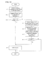
- FIG. 10 is a flowchart illustrating a procedure of the light control of the third embodiment.
- FIG. 1 is a block diagram illustrating a vehicle light control device (hereinafter simply referred to as a “light control device”) according to a first embodiment.
- a vehicle light control device hereinafter simply referred to as a “light control device”
- a light control device 100 includes an infrared sensor 1 , an infrared illuminance detector 2 , a visible-light sensor 3 , a visible-light illuminance detector 4 , a controller 5 , and a storage 6 .
- the infrared sensor 1 is provided in a dashboard in a vehicle to detect an infrared ray around the vehicle.
- the infrared illuminance detector 2 detects infrared illuminance from an output of the infrared sensor 1 .
- the visible-light sensor 3 is provided in the dashboard in the vehicle to detect visible light around the vehicle.
- the visible-light illuminance detector 4 detects visible-light illuminance from the output of the visible-light sensor 3 .
- a lighting threshold ⁇ (a first lighting threshold) is stored in the storage 6 .
- the controller 5 controls lighting of a light 7 based on the infrared illuminance detected by the infrared illuminance detector 2 , the visible-light illuminance detected by the visible-light illuminance detector 4 , and the lighting threshold ⁇ stored in the storage 6 .
- the controller 5 includes a CPU (Central Processing Unit) and a driving circuit for the light 7 .
- a control program (not illustrated) necessary for an operation of the CPU is stored in the storage 6 .
- the light 7 includes vehicle exterior lights such as a headlight and an auxiliary light.
- FIG. 2 illustrates spectral illuminance at daytime and dusk with respect to the visible light and the infrared ray.
- the visible-light illuminance tends to be larger than the infrared illuminance at the daytime, and there is no significant difference between the infrared illuminance and the visible-light illuminance at the dusk. That is, the dusk is smaller than the daytime in difference between the infrared illuminance and the visible-light illuminance. Therefore, the illuminance difference between the infrared illuminance and the visible-light illuminance has a time change in FIG. 3 from the daytime to the dusk.
- the light 7 is turned on at a clock time t1 when the illuminance difference in FIG. 3 becomes the lighting threshold ⁇ or less.
- the lighting threshold ⁇ is set to the illuminance difference between the infrared illuminance and the visible-light illuminance when the surroundings of the vehicle become gloom in which the light needs to be lit. Therefore, the light 7 can surely be turned on at the time when the lighting is required.
- Step S 1 the infrared illuminance detector 2 detects the infrared illuminance from the output of the infrared sensor 1 .
- Step S 2 the visible-light illuminance detector 4 detects the visible-light illuminance from the output of the visible-light sensor 3 .
- the orders of Steps S 1 and S 2 may be replaced for each other. Pieces of processing in Steps S 1 and S 2 may concurrently be performed.
- Step S 3 the controller 5 calculates a difference between the infrared illuminance detected in Step S 1 and the visible-light illuminance detected in Step S 2 , namely, the illuminance difference.
- an average value of the illuminance over a whole wavelength range in an infrared region in FIG. 2 or an average value of the illuminance at a specific wavelength may be used as a value of the infrared illuminance.
- an average value of the illuminance over a whole wavelength range in a visible-light region in FIG. 2 or an average value of the illuminance at a specific wavelength may be used as a value of the visible-light illuminance.
- Step S 4 the controller 5 compares the illuminance difference calculated in Step S 3 to the lighting threshold ⁇ .
- Step S 5 as a result of the comparison in Step S 4 , the controller 5 determines whether the illuminance difference between the infrared illuminance and the visible-light illuminance is less than or equal to the lighting threshold ⁇ . When the illuminance difference is greater than the lighting threshold ⁇ (NO in Step S 5 ), a determination that the lighting of the light 7 is not required is made to end the processing.
- Step S 6 the controller 5 determines that the surroundings of the vehicle becomes the gloom in which the light needs to be lit, and turns on the light 7 .
- the controller 5 determines that the surroundings of the vehicle becomes the gloom in which the light needs to be lit, and turns on the light 7 .
- all the vehicle exterior lights may be lit, or only the necessary vehicle exterior light may be lit.
- only the headlight may be lit, or only the auxiliary light may be lit.
- both the headlight and the auxiliary light may be lit.
- the illuminance difference is compared to the lighting threshold ⁇ to control the lighting of the light 7 .
- the lighting threshold ⁇ to control the lighting using only the infrared sensor.
- both the infrared sensor 1 and the visible-light sensor 3 are used, and the infrared illuminance and the visible-light illuminance are used, so that the gloom in which the light needs to be turned on can rapidly and correctly be detected at the dusk.
- the light 7 can be turned on in early timing to prevent the increase of the risk of the accident generation caused by the delay of the lighting.
- FIG. 5 is a block diagram illustrating a vehicle light control device 200 of the second embodiment.
- a lighting threshold ⁇ (a second lighting threshold) is stored in the storage 6 . Because other configurations are identical to those in FIG. 1 , the description is omitted.
- the lighting threshold ⁇ is set to the value of the infrared illuminance, at which the surroundings become the darkness in which the light needs to be turned on when the vehicle goes in the tunnel.
- the infrared ray included in the sunlight is cut off even at the daytime, and usually a light source emitting the infrared ray does not exist.
- the infrared illuminance decreases rapidly as illustrated by an alternate long and short dash line in FIG. 6 . Therefore, in FIG. 6 , the light 7 is turned on at a clock time t2 when the infrared illuminance becomes the lighting threshold ⁇ or less. Accordingly, the light 7 can surely be turned on at the time when the vehicle goes in the tunnel.
- the lighting at the dusk is identical to that of the first embodiment. That is, in FIG. 6 , the light 7 is turned on at a clock time t3 when the illuminance difference between the infrared illuminance and the visible-light illuminance becomes the lighting threshold ⁇ or less. Therefore, at the dusk, the light 7 can surely be turned on in the precise timing.
- FIG. 7 the processing in the step identical to that in FIG. 4 is designated by the identical numeral.
- Step S 1 the infrared illuminance detector 2 detects the infrared illuminance from the output of the infrared sensor 1 .
- Step S 1 a the controller 5 compares the infrared illuminance detected in Step S 1 to the lighting threshold ⁇ .
- Step S 1 b as a result of the comparison in Step S 1 a, the controller 5 determines whether the infrared illuminance is less than or equal to the lighting threshold ⁇ . When the infrared illuminance is less than or equal to the lighting threshold (YES in Step S 1 b ), the determination that the vehicle goes in the tunnel is made, and the flow goes to Step S 6 .
- Step S 6 the controller 5 turns on the light 7 .
- Step S 2 when the infrared illuminance is greater than the lighting threshold ⁇ (NO in Step S 1 b ), the flow goes to Step S 2 .
- the pieces of processing in Steps S 2 to S 5 are identical to those in FIG. 4 . That is, the visible-light illuminance is detected in Step S 2 , the illuminance difference is calculated in Step S 3 , and the illuminance difference is compared to the lighting threshold ⁇ in Step S 4 .
- the processing is ended when the illuminance difference is greater than the lighting threshold ⁇ (NO in Step S 5 ).
- the illuminance difference is less than or equal to the lighting threshold ⁇ (YES in Step S 5 )
- the determination that the surroundings of the vehicle become gloomy at the dusk is made, and the light 7 is turned on in Step S 6 .
- the infrared sensor 1 is used in the automatic light control at both the dusk and the time when the vehicle goes in the tunnel. Therefore, the light 7 can be turned on in the precise timing in both the cases without adding a new sensor.
- FIG. 8 is a block diagram illustrating a vehicle light control device 300 of the third embodiment.
- a lighting threshold ⁇ (a third lighting threshold) is stored in the storage 6 . Because other configurations are identical to those in FIG. 1 , the description is omitted.
- the lighting threshold ⁇ is set to the value of the visible-light illuminance, at which the surroundings become the darkness in which the light needs to be turned on when the vehicle goes in the tunnel. Because usually a light source emitting the visible light exists in the tunnel, sometimes a precise determination whether the light needs to be turned on is hardly made from the change in visible-light illuminance. However, whether the light needs to be turned on can be determined from the change in visible-light illuminance when the visible light source does not exist in the tunnel (for example, a short tunnel), or when the illuminance is low in the tunnel even if the visible light source exists.
- the third embodiment is suitable for these cases.
- the visible-light illuminance decreases rapidly as illustrated by the alternate long and short dash line in FIG. 9 , in the case where the visible light source does not exist in the tunnel, or in the case where the illuminance is low even if the visible light source exists in the tunnel. Therefore, in FIG. 9 , the light 7 is turned on at a clock time t4 when the visible-light illuminance becomes the lighting threshold ⁇ or less. Accordingly, the light 7 can surely be turned on at the time when the vehicle goes in the tunnel.
- the lighting at the dusk is identical to that of the first embodiment. That is, in FIG. 9 , the light 7 is turned on at a clock time t5 when the illuminance difference between the infrared illuminance and the visible-light illuminance becomes the lighting threshold ⁇ or less. Therefore, at the dusk, the light 7 can surely be turned on in the precise timing.
- FIG. 10 A series of steps of the light control of the third embodiment will be described with reference to a flowchart in FIG. 10 .
- the processing in the step identical to that in FIG. 4 is designated by the identical numeral.
- Step S 2 the processing in Step S 2 is initially performed.
- the visible-light illuminance detector 4 detects the visible-light illuminance from the output of the visible-light sensor 3 .
- Step S 2 a the controller 5 compares the visible-light illuminance detected in Step S 2 to the lighting threshold ⁇ .
- Step S 2 b as a result of the comparison in Step S 2 a, the controller 5 determines whether the visible-light illuminance is less than or equal to the lighting threshold ⁇ .
- Step S 6 the controller 5 turns on the light 7 .
- Step S 2 b when the visible-light illuminance is greater than the threshold ⁇ (NO in Step S 2 b ), the flow proceeds to Step S 1 .
- the pieces of processing in Steps S 1 and S 3 to S 5 are identical to those in FIG. 4 . That is, the infrared illuminance is detected in Step S 1 , the illuminance difference is calculated in Step S 3 , and the illuminance difference is compared to the lighting threshold ⁇ in Step S 4 .
- the processing is ended when the illuminance difference is greater than the lighting threshold ⁇ (NO in Step S 5 ).
- the illuminance difference is less than or equal to the lighting threshold ⁇ (YES in Step S 5 )
- the determination that the surroundings of the vehicle become gloomy at the dusk is made, and the light 7 is turned on in Step S 6 .
- the visible-light sensor 3 is used in the automatic light control at both the dusk and the time when the vehicle goes in the tunnel. Therefore, the light 7 can be turned on in the precise timing in both the cases without adding a new sensor.
- the present invention is not limited to the above embodiments.
- the infrared sensor 1 and the visible-light sensor 3 are provided in the dashboard in the vehicle by way of example.
- the infrared sensor 1 and the visible-light sensor 3 may be provided anywhere in the vehicle as long as the illuminance around the vehicle can be detected. Accordingly, for example, the infrared sensor 1 and the visible-light sensor 3 may be provided on a roof of the vehicle.
- the light control in the case where the vehicle goes in the tunnel is described by way of example.
- one or more embodiments of the present invention can also be applied to the light control in the case where the vehicle goes in the dark places such as under the elevated structure and in the shadow of the building.
Applications Claiming Priority (2)
| Application Number | Priority Date | Filing Date | Title |
|---|---|---|---|
| JP2012155485A JP5661072B2 (ja) | 2012-07-11 | 2012-07-11 | 車両用ライト制御装置 |
| JP2012-155485 | 2012-07-11 |
Publications (2)
| Publication Number | Publication Date |
|---|---|
| US20140015406A1 US20140015406A1 (en) | 2014-01-16 |
| US8941260B2 true US8941260B2 (en) | 2015-01-27 |
Family
ID=49781670
Family Applications (1)
| Application Number | Title | Priority Date | Filing Date |
|---|---|---|---|
| US13/938,393 Active 2033-07-18 US8941260B2 (en) | 2012-07-11 | 2013-07-10 | Vehicle light control device |
Country Status (4)
| Country | Link |
|---|---|
| US (1) | US8941260B2 (zh) |
| JP (1) | JP5661072B2 (zh) |
| CN (1) | CN103538517B (zh) |
| DE (1) | DE102013213160A1 (zh) |
Cited By (1)
| Publication number | Priority date | Publication date | Assignee | Title |
|---|---|---|---|---|
| US20170225611A1 (en) * | 2014-08-07 | 2017-08-10 | Lg Electronics Inc. | Vehicle head lamp driving apparatus and vehicle provided with same |
Families Citing this family (9)
| Publication number | Priority date | Publication date | Assignee | Title |
|---|---|---|---|---|
| CN105555605B (zh) * | 2013-09-20 | 2017-08-29 | 本田技研工业株式会社 | 车灯控制装置 |
| US11812525B2 (en) * | 2017-06-27 | 2023-11-07 | Wangs Alliance Corporation | Methods and apparatus for controlling the current supplied to light emitting diodes |
| JP2019090662A (ja) * | 2017-11-14 | 2019-06-13 | パナソニックIpマネジメント株式会社 | 光検出装置 |
| JP7008534B2 (ja) * | 2018-02-22 | 2022-01-25 | 日立Astemo株式会社 | 車両用灯具の制御装置 |
| JP7095658B2 (ja) * | 2019-07-11 | 2022-07-05 | トヨタ自動車株式会社 | 車載機器制御装置 |
| US11565624B2 (en) * | 2020-01-23 | 2023-01-31 | Ford Global Technologies, Llc | Dimmable external vehicle lighting and methods of use |
| KR102529736B1 (ko) * | 2021-04-29 | 2023-05-09 | 주식회사 경신 | 차량의 오토라이트 제어 장치 및 방법 |
| US11812532B2 (en) | 2021-05-27 | 2023-11-07 | Wangs Alliance Corporation | Multiplexed segmented lighting lamina |
| US11802682B1 (en) | 2022-08-29 | 2023-10-31 | Wangs Alliance Corporation | Modular articulating lighting |
Citations (11)
| Publication number | Priority date | Publication date | Assignee | Title |
|---|---|---|---|---|
| US5329206A (en) * | 1991-05-06 | 1994-07-12 | Lectron Products, Inc. | Automatic headlamp dimmer having improved signal discrimination and signal processing |
| JPH1044860A (ja) | 1996-08-02 | 1998-02-17 | Toyota Motor Corp | 車両用ライト自動点消灯装置 |
| JPH1090759A (ja) | 1996-09-12 | 1998-04-10 | Olympus Optical Co Ltd | ストロボ制御装置 |
| JP2001163115A (ja) | 1999-12-06 | 2001-06-19 | Niles Parts Co Ltd | 照明灯制御装置 |
| US20020163444A1 (en) * | 1997-05-30 | 2002-11-07 | Budnovitch William F. | User assistance system for an interactive facility |
| JP2007302046A (ja) | 2006-05-09 | 2007-11-22 | Denso Corp | 車両用オートライト装置 |
| JP2008080932A (ja) | 2006-09-27 | 2008-04-10 | Denso Corp | 車両用ライト制御装置 |
| US20090284361A1 (en) * | 2008-05-19 | 2009-11-19 | John Boddie | Driver scoring system with lane changing detection and warning system |
| US20100309024A1 (en) * | 2007-12-21 | 2010-12-09 | Yvan Mimeault | Parking management system and method using lighting system |
| US20110012396A1 (en) * | 2009-07-15 | 2011-01-20 | Laake Elizabeth T | Cup holder and pivoting armrest |
| US8600656B2 (en) * | 2007-06-18 | 2013-12-03 | Leddartech Inc. | Lighting system with driver assistance capabilities |
Family Cites Families (5)
| Publication number | Priority date | Publication date | Assignee | Title |
|---|---|---|---|---|
| JPS60143147A (ja) * | 1983-12-28 | 1985-07-29 | Stanley Electric Co Ltd | 自動車用灯具の点滅制御装置 |
| JPH06143147A (ja) * | 1992-11-04 | 1994-05-24 | Inax Corp | ショットブラスト装置の制御方法 |
| EP1196306B1 (en) * | 1998-10-12 | 2004-06-16 | Control Devices, Inc. | Ambient light sensor |
| JP2005199974A (ja) * | 2004-01-19 | 2005-07-28 | Denso Corp | 車両用ライト制御装置 |
| JP2010098358A (ja) * | 2008-10-14 | 2010-04-30 | Panasonic Corp | 撮像素子および撮像装置 |
-
2012
- 2012-07-11 JP JP2012155485A patent/JP5661072B2/ja active Active
-
2013
- 2013-07-04 CN CN201310279197.2A patent/CN103538517B/zh active Active
- 2013-07-04 DE DE102013213160.7A patent/DE102013213160A1/de not_active Ceased
- 2013-07-10 US US13/938,393 patent/US8941260B2/en active Active
Patent Citations (13)
| Publication number | Priority date | Publication date | Assignee | Title |
|---|---|---|---|---|
| US5329206A (en) * | 1991-05-06 | 1994-07-12 | Lectron Products, Inc. | Automatic headlamp dimmer having improved signal discrimination and signal processing |
| JPH1044860A (ja) | 1996-08-02 | 1998-02-17 | Toyota Motor Corp | 車両用ライト自動点消灯装置 |
| JPH1090759A (ja) | 1996-09-12 | 1998-04-10 | Olympus Optical Co Ltd | ストロボ制御装置 |
| US20020163444A1 (en) * | 1997-05-30 | 2002-11-07 | Budnovitch William F. | User assistance system for an interactive facility |
| JP2001163115A (ja) | 1999-12-06 | 2001-06-19 | Niles Parts Co Ltd | 照明灯制御装置 |
| US20070285019A1 (en) * | 2006-05-09 | 2007-12-13 | Denso Corporation | Automatic lighting device and method for controlling light |
| JP2007302046A (ja) | 2006-05-09 | 2007-11-22 | Denso Corp | 車両用オートライト装置 |
| US7639149B2 (en) | 2006-05-09 | 2009-12-29 | Denso Corporation | Automatic lighting device and method for controlling light |
| JP2008080932A (ja) | 2006-09-27 | 2008-04-10 | Denso Corp | 車両用ライト制御装置 |
| US8600656B2 (en) * | 2007-06-18 | 2013-12-03 | Leddartech Inc. | Lighting system with driver assistance capabilities |
| US20100309024A1 (en) * | 2007-12-21 | 2010-12-09 | Yvan Mimeault | Parking management system and method using lighting system |
| US20090284361A1 (en) * | 2008-05-19 | 2009-11-19 | John Boddie | Driver scoring system with lane changing detection and warning system |
| US20110012396A1 (en) * | 2009-07-15 | 2011-01-20 | Laake Elizabeth T | Cup holder and pivoting armrest |
Non-Patent Citations (1)
| Title |
|---|
| Japanese Office Action for Application No. 2012-155485, mailed on Jun. 24, 2014 (8 pages). |
Cited By (2)
| Publication number | Priority date | Publication date | Assignee | Title |
|---|---|---|---|---|
| US20170225611A1 (en) * | 2014-08-07 | 2017-08-10 | Lg Electronics Inc. | Vehicle head lamp driving apparatus and vehicle provided with same |
| US10029607B2 (en) * | 2014-08-07 | 2018-07-24 | Lg Electronics Inc. | Vehicle head lamp driving apparatus and vehicle provided with same |
Also Published As
| Publication number | Publication date |
|---|---|
| CN103538517B (zh) | 2016-02-10 |
| CN103538517A (zh) | 2014-01-29 |
| US20140015406A1 (en) | 2014-01-16 |
| JP2014015169A (ja) | 2014-01-30 |
| JP5661072B2 (ja) | 2015-01-28 |
| DE102013213160A1 (de) | 2014-01-16 |
Similar Documents
| Publication | Publication Date | Title |
|---|---|---|
| US8941260B2 (en) | Vehicle light control device | |
| JP4573220B2 (ja) | 車両用ライト制御装置 | |
| EP2570302A2 (en) | Vehicular light automatic control device | |
| CA2953299C (en) | Lighting device | |
| JP2012171393A (ja) | 車両用ライト制御装置 | |
| JP7052216B2 (ja) | ライトセンサ | |
| JP2012232623A (ja) | 車両用点灯制御装置 | |
| JP2008080932A (ja) | 車両用ライト制御装置 | |
| TW201605671A (zh) | 智慧型大燈切換系統 | |
| JP5805291B2 (ja) | 車両用ライト制御装置 | |
| JP2015056256A (ja) | 車両用灯火器の自動点滅装置 | |
| JP6022426B2 (ja) | 車両用ライト制御装置 | |
| KR102127158B1 (ko) | 차량 글라스의 명암 조절시스템 및 그 방법 | |
| KR101092827B1 (ko) | 후미등 점등 시스템 | |
| JP5893480B2 (ja) | 照明装置及びそれを備えた照明システム | |
| KR20200027198A (ko) | 차량용 헤드램프 제어 장치 및 방법 | |
| JP6059050B2 (ja) | 車両用ライト制御装置 | |
| JP2004142536A (ja) | オートライトシステム及びそれを備えた自動車、並びに、それに用いられる日照センサ | |
| JP2009056905A (ja) | 車両用オートライト装置 | |
| JP5555562B2 (ja) | ライトの点消灯制御装置 | |
| JP4862364B2 (ja) | 照明制御装置 | |
| JP2010120457A (ja) | 車両用前照灯装置 | |
| KR20170040912A (ko) | 차속에 따른 led 헤드램프 조도 제어 방법 및 장치 | |
| KR101360071B1 (ko) | 차량의 오토 라이트 시스템 및 그 제어 방법 | |
| JP2021087119A (ja) | 車内撮像装置、乗員監視装置 |
Legal Events
| Date | Code | Title | Description |
|---|---|---|---|
| AS | Assignment |
Owner name: OMRON AUTOMOTIVE ELECTRONICS CO., LTD., JAPAN Free format text: ASSIGNMENT OF ASSIGNORS INTEREST;ASSIGNORS:FUJIWARA, HIROYUKI;TERAYAMA, TAKAHITO;REEL/FRAME:030776/0995 Effective date: 20130612 |
|
| STCF | Information on status: patent grant |
Free format text: PATENTED CASE |
|
| MAFP | Maintenance fee payment |
Free format text: PAYMENT OF MAINTENANCE FEE, 4TH YEAR, LARGE ENTITY (ORIGINAL EVENT CODE: M1551) Year of fee payment: 4 |
|
| MAFP | Maintenance fee payment |
Free format text: PAYMENT OF MAINTENANCE FEE, 8TH YEAR, LARGE ENTITY (ORIGINAL EVENT CODE: M1552); ENTITY STATUS OF PATENT OWNER: LARGE ENTITY Year of fee payment: 8 |