US8957504B2 - Integrated structure with a silicon-through via - Google Patents

Integrated structure with a silicon-through via Download PDF

Info

Publication number
US8957504B2
US8957504B2 US13/833,786 US201313833786A US8957504B2 US 8957504 B2 US8957504 B2 US 8957504B2 US 201313833786 A US201313833786 A US 201313833786A US 8957504 B2 US8957504 B2 US 8957504B2
Authority
US
United States
Prior art keywords
conductive
protective structure
silicon
disposed
integrated structure
Prior art date
Legal status (The legal status is an assumption and is not a legal conclusion. Google has not performed a legal analysis and makes no representation as to the accuracy of the status listed.)
Expired - Fee Related
Application number
US13/833,786
Other versions
US20140264916A1 (en
Inventor
Huang Chao-Yuan
Ho Yueh-Feng
Yang Ming-Sheng
Chen Hwi-Huang
Current Assignee (The listed assignees may be inaccurate. Google has not performed a legal analysis and makes no representation or warranty as to the accuracy of the list.)
IPEnval Consultant Inc
IP Enval Consultant Inc
Original Assignee
IP Enval Consultant Inc
Priority date (The priority date is an assumption and is not a legal conclusion. Google has not performed a legal analysis and makes no representation as to the accuracy of the date listed.)
Filing date
Publication date
Application filed by IP Enval Consultant Inc filed Critical IP Enval Consultant Inc
Priority to US13/833,786 priority Critical patent/US8957504B2/en
Assigned to IPEnval Consultant Inc. reassignment IPEnval Consultant Inc. ASSIGNMENT OF ASSIGNORS INTEREST (SEE DOCUMENT FOR DETAILS). Assignors: HUANG, CHAO-YUAN, CHEN, HWI-HUANG, HO, YUEH-FENG, YANG, MING-SHENG
Publication of US20140264916A1 publication Critical patent/US20140264916A1/en
Application granted granted Critical
Publication of US8957504B2 publication Critical patent/US8957504B2/en
Expired - Fee Related legal-status Critical Current
Anticipated expiration legal-status Critical

Links

Images

Classifications

    • HELECTRICITY
    • H01ELECTRIC ELEMENTS
    • H01LSEMICONDUCTOR DEVICES NOT COVERED BY CLASS H10
    • H01L23/00Details of semiconductor or other solid state devices
    • H01L23/48Arrangements for conducting electric current to or from the solid state body in operation, e.g. leads, terminal arrangements ; Selection of materials therefor
    • H01L23/481Internal lead connections, e.g. via connections, feedthrough structures
    • HELECTRICITY
    • H01ELECTRIC ELEMENTS
    • H01LSEMICONDUCTOR DEVICES NOT COVERED BY CLASS H10
    • H01L23/00Details of semiconductor or other solid state devices
    • H01L23/52Arrangements for conducting electric current within the device in operation from one component to another, i.e. interconnections, e.g. wires, lead frames
    • H01L23/522Arrangements for conducting electric current within the device in operation from one component to another, i.e. interconnections, e.g. wires, lead frames including external interconnections consisting of a multilayer structure of conductive and insulating layers inseparably formed on the semiconductor body
    • HELECTRICITY
    • H01ELECTRIC ELEMENTS
    • H01LSEMICONDUCTOR DEVICES NOT COVERED BY CLASS H10
    • H01L23/00Details of semiconductor or other solid state devices
    • H01L23/544Marks applied to semiconductor devices or parts, e.g. registration marks, alignment structures, wafer maps
    • HELECTRICITY
    • H01ELECTRIC ELEMENTS
    • H01LSEMICONDUCTOR DEVICES NOT COVERED BY CLASS H10
    • H01L2223/00Details relating to semiconductor or other solid state devices covered by the group H01L23/00
    • H01L2223/544Marks applied to semiconductor devices or parts
    • H01L2223/5442Marks applied to semiconductor devices or parts comprising non digital, non alphanumeric information, e.g. symbols
    • HELECTRICITY
    • H01ELECTRIC ELEMENTS
    • H01LSEMICONDUCTOR DEVICES NOT COVERED BY CLASS H10
    • H01L2223/00Details relating to semiconductor or other solid state devices covered by the group H01L23/00
    • H01L2223/544Marks applied to semiconductor devices or parts
    • H01L2223/54426Marks applied to semiconductor devices or parts for alignment
    • HELECTRICITY
    • H01ELECTRIC ELEMENTS
    • H01LSEMICONDUCTOR DEVICES NOT COVERED BY CLASS H10
    • H01L2223/00Details relating to semiconductor or other solid state devices covered by the group H01L23/00
    • H01L2223/544Marks applied to semiconductor devices or parts
    • H01L2223/54453Marks applied to semiconductor devices or parts for use prior to dicing
    • HELECTRICITY
    • H01ELECTRIC ELEMENTS
    • H01LSEMICONDUCTOR DEVICES NOT COVERED BY CLASS H10
    • H01L2924/00Indexing scheme for arrangements or methods for connecting or disconnecting semiconductor or solid-state bodies as covered by H01L24/00
    • H01L2924/0001Technical content checked by a classifier
    • H01L2924/0002Not covered by any one of groups H01L24/00, H01L24/00 and H01L2224/00

Landscapes

  • Physics & Mathematics (AREA)
  • Condensed Matter Physics & Semiconductors (AREA)
  • General Physics & Mathematics (AREA)
  • Engineering & Computer Science (AREA)
  • Computer Hardware Design (AREA)
  • Microelectronics & Electronic Packaging (AREA)
  • Power Engineering (AREA)
  • Internal Circuitry In Semiconductor Integrated Circuit Devices (AREA)

Abstract

An integrated structure with a silicon-through via includes a substrate, a through-silicon via penetrating the substrate, a conductive protective structure surrounding the through-silicon via and a first and a second conductive dummy patterns with different shapes disposed between the through-silicon via and the conductive protective structure.

Description

FIELD OF THE INVENTION
The present invention relates to an integrated structure with a silicon-through via.
BACKGROUND OF THE INVENTION
To save precious layout space or increase interconnection efficiency, multiple chips of integrated circuits (ICs) can be stacked together as a single IC package. To that end, a three-dimensional (3D) stack packaging technology is used to package the chips of integrated circuits. Through-silicon vias (TSVs) are widely used to accomplish the 3D stack packaging technology. A through-silicon via is a vertical conductive via completely passing through a silicon wafer, a silicon board, a substrate of any material or die. Nowadays, a 3D integrated circuit (3D IC) is applied to a lot of fields such as memory stacks, image sensors or the like.
Compared to a single transistor or a single interconnect metal line, a through-silicon via comes with a size of hundred fold or more. To share the same manufacturing process with integrated circuits would mean difficulties to control process uniformity and/or keep process window. Furthermore, the gigantic TSVs would produce mechanical stress and electrical interference affecting the devices around them. Hence, there is a need to completely eliminate or at least reduce this issue.
SUMMARY OF THE INVENTION
In one embodiment of the present invention, an integrated structure with a silicon-through via is provided to comprise a substrate, a through-silicon via penetrating the substrate, a conductive protective structure surrounding the through-silicon via and a first and a second conductive dummy patterns with different shapes disposed between the through-silicon via and the conductive protective structure.
In another embodiment of the present invention, an integrated structure with a silicon-through via is provided to comprise a substrate, a through-silicon via penetrating the substrate, a conductive protective structure surrounding the through-silicon via and a first and a second alignment marks with different shapes disposed between the through-silicon via and the conductive protective structure.
BRIEF DESCRIPTION OF THE DRAWINGS
The above objects and advantages of the present invention will become more readily apparent to those ordinarily skilled in the art after reviewing the following detailed description and accompanying drawings, in which:
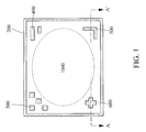
FIG. 1 shows a schematic top view of an integrated structure with a through-silicon via (TSV) in accordance with an embodiment of the present invention;
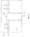
FIG. 2 shows a schematic cross-sectional view of the integrated structure with a TSV taken along line A-A′ of FIG. 1 in accordance with an embodiment of the present invention;
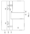
FIG. 3 shows a schematic cross-sectional view of the integrated structure with a TSV taken along line A-A′ of FIG. 1 in accordance with another embodiment of the present invention.
DETAILED DESCRIPTION OF PREFERRED EMBODIMENTS
The following is the detailed description of the preferred embodiments of this invention. All the elements, sub-elements, structures, materials, arrangements recited herein can be combined in any way and in any order into new embodiments, and these new embodiments should fall in the scope of this invention defined by the appended claims. A person skilled in the art, upon reading this invention, should be able to modify and change the elements, sub-elements, structures, materials, arrangements recited herein without being apart from the principle and spirit of this invention. Therefore, these modifications and changes should fall in the scope of this invention defined only by the following claims.
There are a lot of embodiments and figures in this application. To avoid confusions, similar components are represented by same or similar numerals. To avoid complexity and confusions, only one of the repetitive components is marked. Figures are meant to deliver the principle and spirits of this invention, so the distance, size, ratio, shape, connection relationship, etc. are examples instead of realities. Other distance, size, ratio, shape, connection relationship, etc. capable of achieving the same functions or results can be adopted as equivalents.
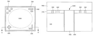
Now refer to FIG. 1, which shows a schematic top view of an integrated structure with a through-silicon via (TSV) 1000 in accordance with an embodiment of the present invention. In the present invention, the focus is on what's around TSVs not what's above TSVs, so the interconnects above TSVs are omitted to keep the figures plain and simple. The TSV 1000 (in some references also known as through electrode, conductive post . . . etc.) passes “through” a substrate 100 (not shown in FIG. 1, please refer to FIG. 2-3) and physically and electrically connect the backside and front side of substrate 100. The TSV 1000 is configured to couple operation voltage VSS, VDD or operational signal to the integrated circuits (not shown) formed on the substrate 100. Compared to normal active devices such as transistors, TSV 1000 has a much bigger size in a scale of micrometers. In one embodiment, TSV 1000 has a diameter of 30 μm. In another embodiment, TSV 1000 has a diameter of 10 μm. In a further embodiment, TSV 1000 has a diameter of 6 μm.
Still refer to FIG. 1, since the gigantic TSV 1000 may produce mechanical stress and electrical interference affecting the active devices (not shown) such as MOS transistors around it, a protective structure 200 is disposed to surround the TSV 1000 in order to isolate TSV 1000 physically and electrically from the active devices around it. The protective structure 200 shown in FIG. 1 has a rectangle or square shape. However, the protective structure 200 is not limited in its shape and how far it extends vertically as long as it is a closed structure surrounding the TSV within it.
Aside from the mechanical stress and electrical interference caused by the TSV 1000, its gigantic size would also induce non-uniformity in thickness, in critical dimension (CD) and in profile after some processes sensitive to pattern density/pattern distribution such as etching processes and chemical mechanical polishing (CMP) processes. For overcoming these process difficulties, dummy patterns 200 and 300 with different shapes are introduced between the empty space between the protective structure 200 and the TSV 1000. The size and shape of the dummy patterns 200 and 300 need not to be limited. Although only two kinds of dummy patterns (that is 200 and 300) are shown in FIG. 1, more kinds of dummy patterns with different geometric features may be introduced as long as they can help to improve process uniformity and to relief mechanical stress caused by TSV 1000.
In most of the integrated circuit (IC) manufacturing processes, mass amount of alignment marks are needed for photolithography process, defect inspections . . . etc. These marks are usually space demanding and contributes nothings to the electrical functions. In the present invention, some of these marks such as alignment marks 500 and 600 may be disposed around the TSV 1000 and the protective structure 200 to save space. The shapes, sizes and functions of these marks are not limited as long as they can perform the functions they supposed to perform.
Now please refer to FIG. 2, which shows a schematic cross-sectional view of the integrated structure with the TSV 1000 taken along line A-A′ of FIG. 1 in accordance with an embodiment of the present invention. A substrate 100 is provided. As shown in FIG. 2, TSV 1000 penetrates the substrate 100, couple the front side and backside of the substrate 100 and protrude from the front side. The substrate 100 can be a Si substrate, a polymer substrate, a silicon-on-insulator substrate, a SiC substrate, a composite substrate . . . etc. The backside is the side having no active devices such as transistors formed thereon. The backside of the substrate 100 is the opposite side of the front side of the substrate 100, wherein active devices such as transistors and interconnect structures are formed on the front side.
The TSV 1000 shown in FIG. 2-3 seems to be a TSV made from a via middle process, however TSV 1000 may be made from a via first process (via is made before transistors), a via middle process (via is made after transistors and during lower interconnects) or a via last process (via is made after interconnects). No matter what kind of process is adopted to fabricate TSV 1000, the basic structure of TSV 1000 is the same: a through-silicon hole, a dielectric layer 800 lining on the wall of the through-silicon hole, and a conductive material 900 filled in the through-silicon hole. The material/materials used for the dielectric layer 800 and the conductive material 900 may depend on the manufacturing process and the physical properties needed. Silicon oxide and/or silicon nitride are the most commonly used material/materials for the dielectric layer 800. As to the conductive material 900, it may comprise a barrier/glue layer material such as Ta, TaN, Ti, TiN, W, WN, Mo, Mn, Cu and a low-resistivity material such as W, Cu, Al, poly silicon. It is noted that the dielectric layer 800 may rather be formed by thermal oxidation than deposition, then the dielectric layer 800 may not extend to the inter-layer dielectric layer 150 or the interconnect/device layer 130.
Disposed around the TSV 1000 is the inter-layer dielectric layer 150. Inter-layer dielectric layer 150 may be a single-layered or multi-layered structure comprising one or more dielectric material selected from silicon dioxide, silicon nitride, SiC, SiON, SiCN, TEOS-based silicon dioxide, low-k dielectric materials . . . etc. As shown in FIG. 2, the protective structure 200 and marks 500 and 600 are conductive contacts embedded in the inter-layer dielectric layer 150. They can be made by the same single damascene processes. That is, they may be formed by forming one or more contact holes, forming one or more conductive materials on the substrate filling in the contact holes then performing a chemical mechanical polishing process to remove excess materials and form a global flat surface. The conductive materials used for the protective structure 200 and marks 500 and 600 comprise a barrier/glue material and a low-resistivity filling material. The barrier/glue material may be selected from Ta, TaN, Ti, TiN, W, WN, Mo, Mn, Cu, and the barrier/glue material preferably be Ta/TaN or Ti/TiN. The low-resistivity filling material may be selected from W, Cu, Al, poly silicon and the low-resistivity filling material preferably is W. Although not shown in FIG. 2, dummy patterns 300 and 400 are also conductive contacts embedded in the inter-layer dielectric layer 150. It appears from FIG. 1, dummy patterns 300 and 400, marks 500 and 600 are disposed at four different corners of the protective structure 200, but the present invention is not limited. Different dummy patterns can be disposed at the same corner of the protective structure 200 and a plurality of marks of the same shape can be disposed at the same corner of the protective structure 200.
Disposed above the TSV 1000, inter-layer dielectric layer 150, protective structure 200, marks 500 and 600, and dummy patterns 300 and 400 is a interconnect layer 900. Interconnect layer 900 represents all the inter-metal dielectric layers and all the interconnect structures embedded within. It should be understood, FIG. 1-3 only show a part of a complete picture, therefore the substrate 100 may comprise shallow trench isolation structure and every kinds of doped regions while the inter-layer dielectric layer 150 may comprise active devices such as MOS transistors, passive devices such as resistors and other dummy patterns.
Now please refer to FIG. 3, which shows a schematic cross-sectional view of the integrated structure with TSV taken along line A-A′ of FIG. 1 in accordance with another embodiment of the present invention. Not like the embodiment shown in FIG. 2, in this embodiment dielectric layer 150′ corresponding to the dielectric layer 150 is not directly on the substrate 100 around TSV 1000. Between the dielectric layer 150′ and the substrate 100 is an interconnect/device layer 130. The interconnect/device layer 130 may comprise one or more dielectric layers with interconnect structures embedded therein and/or active devices formed on substrate 100. Aside from the dielectric layer 150′, the protective structure 200 embedded in the inter-layer dielectric layer 150 in FIG. 2 is replaced by protective structure 200′ embedded in the interconnect/device layer 130. The marks 500′ and 600′ in this embodiment corresponding to the marks 500 and 600 are made by dual damascene process instead of single damascene process. From this embodiment, it is clear that the protective structure 200/200′ should be at the same level (embedded in the same dielectric layer) with active devices so it can isolate the TSV 1000 from the active devices. The dummy patterns and the marks between the protective structure and TSV can be at different level (embedded in the different dielectric layer) from the protective structure.
Although not shown in FIGS. 1-3, the substrate 100 may comprise shallow trench isolation structures right beneath the protective structure 200/200′, dummy patterns 300 and 400, and marks 500 and 600 in order to isolate them from other functional active devices or routing interconnect. These shallow trench isolation structures may adapt different shapes and sizes to suit the protective structure 200/200′, dummy patterns 300 and 400, and marks 500 and 600.
In this way, the present invention manages to isolate the TSV from the active devices in order to reduce the impacts caused by TSV on the active devices. The present invention also manages to make good use of the space around TSV and keep good process uniformity by adding marks and dummy patterns around TSV.
While the invention has been described in terms of what is presently considered to be the most practical and preferred embodiments, it is to be understood that the invention needs not be limited to the disclosed embodiment. On the contrary, it is intended to cover various modifications and similar arrangements included within the spirit and scope of the appended claims which are to be accorded with the broadest interpretation so as to encompass all such modifications and similar structures.

Claims (20)

What is claimed is:
1. An integrated structure with a silicon-through via, comprising:
a substrate;
a through-silicon via penetrating the substrate, the through-silicon via comprising a through-silicon hole, a dielectric layer lining on a wall of the through-silicon hole and a conductive material filled in the through-silicon hole;
a conductive protective structure surrounding the through-silicon via; and
a first and a second conductive dummy patterns with different shapes disposed between the through-silicon via and the conductive protective structure,
wherein the first and second conductive dummy patterns are physically separated from the through-silicon via.
2. The integrated structure of claim 1, wherein the conductive protective structure, the first and the second conductive dummy patterns are disposed within the same dielectric layer.
3. The integrated structure of claim 1, wherein the conductive protective structure, the first and the second conductive dummy patterns are disposed within different dielectric layers.
4. The integrated structure of claim 1, wherein the conductive protective structure has a rectangle or square shape.
5. The integrated structure of claim 4, wherein the first and the second conductive dummy patterns are disposed at different corners of the conductive protective structure.
6. The integrated structure of claim 1, further comprising an alignment mark disposed between the conductive protective structure and the through-silicon via.
7. The integrated structure of claim 6, wherein the conductive protective structure and the alignment mark are disposed within the same dielectric layer.
8. The integrated structure of claim 6, wherein the conductive protective structure and the alignment mark are disposed within different dielectric layers.
9. The integrated structure of claim 6, wherein the conductive protective structure has a rectangle or square shape and the alignment mark is disposed at a corner of the conductive protective structure.
10. The integrated structure of claim 6, wherein the alignment mark is configured for photolithography or defect inspection.
11. An integrated structure with a silicon-through via, comprising:
a substrate;
a through-silicon via penetrating the substrate, the through-silicon via comprising a through-silicon hole, a dielectric layer lining on a wall of the through-silicon hole and a conductive material filled in the through-silicon hole;
a conductive protective structure surrounding the through-silicon via; and
a first and a second alignment marks with different shapes disposed between the through-silicon via and the conductive protective structure,
wherein the first and second alignment marks are physically separated from the through-silicon via.
12. The integrated structure of claim 11, wherein the conductive protective structure, the first and the second alignment marks are disposed within the same dielectric layer.
13. The integrated structure of claim 11, wherein the conductive protective structure, the first and the second alignment marks are disposed within different dielectric layers.
14. The integrated structure of claim 11, wherein the conductive protective structure has a rectangle or square shape.
15. The integrated structure of claim 14, wherein the first and the second alignment marks are disposed at different corners of the conductive protective structure.
16. The integrated structure of claim 11, further comprising a conductive dummy pattern disposed between the conductive protective structure and the through-silicon via.
17. The integrated structure of claim 16, wherein the conductive protective structure and the conductive dummy pattern are disposed within the same dielectric layer.
18. The integrated structure of claim 16, wherein the conductive protective structure and the conductive dummy pattern are disposed within different dielectric layers.
19. The integrated structure of claim 16, wherein the conductive protective structure has a rectangle or square shape and the conductive dummy pattern is disposed at a corner of the conductive protective structure.
20. The integrated structure of claim 11, wherein the alignment mark is configured for photolithography or defect inspection.
US13/833,786 2013-03-15 2013-03-15 Integrated structure with a silicon-through via Expired - Fee Related US8957504B2 (en)

Priority Applications (1)

Application Number Priority Date Filing Date Title
US13/833,786 US8957504B2 (en) 2013-03-15 2013-03-15 Integrated structure with a silicon-through via

Applications Claiming Priority (1)

Application Number Priority Date Filing Date Title
US13/833,786 US8957504B2 (en) 2013-03-15 2013-03-15 Integrated structure with a silicon-through via

Publications (2)

Publication Number Publication Date
US20140264916A1 US20140264916A1 (en) 2014-09-18
US8957504B2 true US8957504B2 (en) 2015-02-17

Family

ID=51523941

Family Applications (1)

Application Number Title Priority Date Filing Date
US13/833,786 Expired - Fee Related US8957504B2 (en) 2013-03-15 2013-03-15 Integrated structure with a silicon-through via

Country Status (1)

Country Link
US (1) US8957504B2 (en)

Cited By (6)

* Cited by examiner, † Cited by third party
Publication number Priority date Publication date Assignee Title
US20140239768A1 (en) * 2013-02-27 2014-08-28 Texas Instruments Incorporated Capacitive micromachined ultrasonic transducer (cmut) with through-substrate via (tsv) substrate plug
US10075657B2 (en) 2015-07-21 2018-09-11 Fermi Research Alliance, Llc Edgeless large area camera system
US10107830B2 (en) 2013-02-27 2018-10-23 Texas Instruments Incorporated Method of forming capacitive MEMS sensor devices
US10352991B2 (en) 2015-07-21 2019-07-16 Fermi Research Alliance, Llc Edgeless large area ASIC
US20220157737A1 (en) * 2020-11-13 2022-05-19 Samsung Electronics Co., Ltd. Three dimensional integrated semiconductor architecture and method of manufacturing the same
US11749614B2 (en) 2020-11-05 2023-09-05 Samsung Electronics Co., Ltd. Through-silicon via (TSV) key for overlay measurement, and semiconductor device and semiconductor package including TSV key

Families Citing this family (5)

* Cited by examiner, † Cited by third party
Publication number Priority date Publication date Assignee Title
KR102177702B1 (en) 2014-02-03 2020-11-11 삼성전자주식회사 Via Structures and Semiconductor Devices Having a Via plug
US9425126B2 (en) * 2014-05-29 2016-08-23 Taiwan Semiconductor Manufacturing Company, Ltd. Dummy structure for chip-on-wafer-on-substrate
US9397048B1 (en) * 2015-03-23 2016-07-19 Inotera Memories, Inc. Semiconductor structure and manufacturing method thereof
US9997464B2 (en) * 2016-04-29 2018-06-12 Taiwan Semiconductor Manufacturing Company, Ltd. Dummy features in redistribution layers (RDLS) and methods of forming same
WO2023058327A1 (en) * 2021-10-08 2023-04-13 ソニーセミコンダクタソリューションズ株式会社 Semiconductor device

Citations (27)

* Cited by examiner, † Cited by third party
Publication number Priority date Publication date Assignee Title
US20100121994A1 (en) 2008-11-10 2010-05-13 International Business Machines Corporation Stacked memory array
US7799678B2 (en) 2008-01-30 2010-09-21 Freescale Semiconductor, Inc. Method for forming a through silicon via layout
US20100257495A1 (en) 2009-04-06 2010-10-07 Chan-Liang Wu 3D-IC Verification Method
US20110147909A1 (en) 2009-12-18 2011-06-23 John Hsuan Semicondcutor chip stack and manufacturing method thereof
US7969013B2 (en) * 2009-10-22 2011-06-28 Taiwan Semiconductor Manufacturing Company, Ltd. Through silicon via with dummy structure and method for forming the same
US7989918B2 (en) 2009-01-26 2011-08-02 International Business Machines Corporation Implementing tamper evident and resistant detection through modulation of capacitance
US8008195B2 (en) * 2009-01-23 2011-08-30 Oki Semiconductor Co., Ltd. Method for manufacturing semiconductor device
US8103996B2 (en) 2008-06-24 2012-01-24 Cadence Design Systems, Inc. Method and apparatus for thermal analysis of through-silicon via (TSV)
US8102064B2 (en) * 2010-04-08 2012-01-24 Nanya Technology Corp. Electrical alignment mark set and method for aligning wafer stack
US8136084B2 (en) 2009-09-09 2012-03-13 International Business Machines Corporation Arranging through silicon vias in IC layout
US8143704B2 (en) * 2009-10-02 2012-03-27 Texas Instruments Incorporated Electronic assemblies including mechanically secured protruding bonding conductor joints
US20120106117A1 (en) 2010-11-02 2012-05-03 Georgia Tech Research Corporation Ultra-thin interposer assemblies with through vias
US20120124532A1 (en) 2010-11-11 2012-05-17 International Business Machines Corporation Implementing vertical die stacking to distribute logical function over multiple dies in through-silicon-via stacked semiconductor device
WO2012082092A1 (en) 2010-12-13 2012-06-21 Arm Limited Inter-die connection within an integrated circuit formed of a stack of circuit dies
US8227889B2 (en) * 2008-12-08 2012-07-24 United Microelectronics Corp. Semiconductor device
US20120273782A1 (en) 2011-04-28 2012-11-01 Taiwan Semiconductor Manufacturing Company, Ltd. Interposers of 3-dimensional integrated circuit package systems and methods of designing the same
US8319336B2 (en) 2010-07-08 2012-11-27 Taiwan Semiconductor Manufacturing Company, Ltd. Reduction of etch microloading for through silicon vias
US20120304142A1 (en) 2010-12-09 2012-11-29 Panasonic Corporation Design support device of three-dimensional integrated circuit and method thereof
US8332803B1 (en) 2010-06-28 2012-12-11 Xilinx, Inc. Method and apparatus for integrated circuit package thermo-mechanical reliability analysis
US20120331435A1 (en) 2011-06-27 2012-12-27 Xilinx, Inc. Integrated circuit design using through silicon vias
US8344749B2 (en) 2010-06-07 2013-01-01 Texas Instruments Incorporated Through carrier dual side loop-back testing of TSV die after die attach to substrate
US8350362B2 (en) * 2010-05-28 2013-01-08 Hynix Semiconductor Inc. Semiconductor integrated circuit and method for fabricating the same
US8359554B2 (en) 2008-06-18 2013-01-22 Taiwan Semiconductor Manufacturing Company, Ltd. Verification of 3D integrated circuits
US8362622B2 (en) 2009-04-24 2013-01-29 Synopsys, Inc. Method and apparatus for placing transistors in proximity to through-silicon vias
US20130032799A1 (en) * 2011-08-03 2013-02-07 Taiwan Semiconductor Manufacturing Company, Ltd. Apparatus and Methods for De-Embedding Through Substrate Vias
US20130134583A1 (en) * 2011-05-26 2013-05-30 Kabushiki Kaisha Toshiba Semiconductor device and manufacturing method thereof
US20130341799A1 (en) * 2012-06-21 2013-12-26 Hsin-Yu Chen Through silicon via structure and method of fabricating the same

Patent Citations (27)

* Cited by examiner, † Cited by third party
Publication number Priority date Publication date Assignee Title
US7799678B2 (en) 2008-01-30 2010-09-21 Freescale Semiconductor, Inc. Method for forming a through silicon via layout
US8359554B2 (en) 2008-06-18 2013-01-22 Taiwan Semiconductor Manufacturing Company, Ltd. Verification of 3D integrated circuits
US8103996B2 (en) 2008-06-24 2012-01-24 Cadence Design Systems, Inc. Method and apparatus for thermal analysis of through-silicon via (TSV)
US20100121994A1 (en) 2008-11-10 2010-05-13 International Business Machines Corporation Stacked memory array
US8227889B2 (en) * 2008-12-08 2012-07-24 United Microelectronics Corp. Semiconductor device
US8008195B2 (en) * 2009-01-23 2011-08-30 Oki Semiconductor Co., Ltd. Method for manufacturing semiconductor device
US7989918B2 (en) 2009-01-26 2011-08-02 International Business Machines Corporation Implementing tamper evident and resistant detection through modulation of capacitance
US20100257495A1 (en) 2009-04-06 2010-10-07 Chan-Liang Wu 3D-IC Verification Method
US8362622B2 (en) 2009-04-24 2013-01-29 Synopsys, Inc. Method and apparatus for placing transistors in proximity to through-silicon vias
US8136084B2 (en) 2009-09-09 2012-03-13 International Business Machines Corporation Arranging through silicon vias in IC layout
US8143704B2 (en) * 2009-10-02 2012-03-27 Texas Instruments Incorporated Electronic assemblies including mechanically secured protruding bonding conductor joints
US7969013B2 (en) * 2009-10-22 2011-06-28 Taiwan Semiconductor Manufacturing Company, Ltd. Through silicon via with dummy structure and method for forming the same
US20110147909A1 (en) 2009-12-18 2011-06-23 John Hsuan Semicondcutor chip stack and manufacturing method thereof
US8102064B2 (en) * 2010-04-08 2012-01-24 Nanya Technology Corp. Electrical alignment mark set and method for aligning wafer stack
US8350362B2 (en) * 2010-05-28 2013-01-08 Hynix Semiconductor Inc. Semiconductor integrated circuit and method for fabricating the same
US8344749B2 (en) 2010-06-07 2013-01-01 Texas Instruments Incorporated Through carrier dual side loop-back testing of TSV die after die attach to substrate
US8332803B1 (en) 2010-06-28 2012-12-11 Xilinx, Inc. Method and apparatus for integrated circuit package thermo-mechanical reliability analysis
US8319336B2 (en) 2010-07-08 2012-11-27 Taiwan Semiconductor Manufacturing Company, Ltd. Reduction of etch microloading for through silicon vias
US20120106117A1 (en) 2010-11-02 2012-05-03 Georgia Tech Research Corporation Ultra-thin interposer assemblies with through vias
US20120124532A1 (en) 2010-11-11 2012-05-17 International Business Machines Corporation Implementing vertical die stacking to distribute logical function over multiple dies in through-silicon-via stacked semiconductor device
US20120304142A1 (en) 2010-12-09 2012-11-29 Panasonic Corporation Design support device of three-dimensional integrated circuit and method thereof
WO2012082092A1 (en) 2010-12-13 2012-06-21 Arm Limited Inter-die connection within an integrated circuit formed of a stack of circuit dies
US20120273782A1 (en) 2011-04-28 2012-11-01 Taiwan Semiconductor Manufacturing Company, Ltd. Interposers of 3-dimensional integrated circuit package systems and methods of designing the same
US20130134583A1 (en) * 2011-05-26 2013-05-30 Kabushiki Kaisha Toshiba Semiconductor device and manufacturing method thereof
US20120331435A1 (en) 2011-06-27 2012-12-27 Xilinx, Inc. Integrated circuit design using through silicon vias
US20130032799A1 (en) * 2011-08-03 2013-02-07 Taiwan Semiconductor Manufacturing Company, Ltd. Apparatus and Methods for De-Embedding Through Substrate Vias
US20130341799A1 (en) * 2012-06-21 2013-12-26 Hsin-Yu Chen Through silicon via structure and method of fabricating the same

Cited By (10)

* Cited by examiner, † Cited by third party
Publication number Priority date Publication date Assignee Title
US20140239768A1 (en) * 2013-02-27 2014-08-28 Texas Instruments Incorporated Capacitive micromachined ultrasonic transducer (cmut) with through-substrate via (tsv) substrate plug
US9351081B2 (en) * 2013-02-27 2016-05-24 Texas Instruments Incorporated Capacitive micromachined ultrasonic transducer (CMUT) with through-substrate via (TSV) substrate plug
US9937528B2 (en) 2013-02-27 2018-04-10 Texas Instruments Incorporated Capacitive micromachined ultrasonic transducer (CMUT) forming
US10107830B2 (en) 2013-02-27 2018-10-23 Texas Instruments Incorporated Method of forming capacitive MEMS sensor devices
US10075657B2 (en) 2015-07-21 2018-09-11 Fermi Research Alliance, Llc Edgeless large area camera system
US10352991B2 (en) 2015-07-21 2019-07-16 Fermi Research Alliance, Llc Edgeless large area ASIC
US11012642B2 (en) 2015-07-21 2021-05-18 Fermi Research Alliance, Llc Edgeless large area camera system
US11749614B2 (en) 2020-11-05 2023-09-05 Samsung Electronics Co., Ltd. Through-silicon via (TSV) key for overlay measurement, and semiconductor device and semiconductor package including TSV key
US20220157737A1 (en) * 2020-11-13 2022-05-19 Samsung Electronics Co., Ltd. Three dimensional integrated semiconductor architecture and method of manufacturing the same
US11694968B2 (en) * 2020-11-13 2023-07-04 Samsung Electronics Co., Ltd Three dimensional integrated semiconductor architecture having alignment marks provided in a carrier substrate

Also Published As

Publication number Publication date
US20140264916A1 (en) 2014-09-18

Similar Documents

Publication Publication Date Title
US8957504B2 (en) Integrated structure with a silicon-through via
JP6399887B2 (en) Integrated circuit device having TSV structure and method of manufacturing the same
TWI754962B (en) Semiconductor structure and method of fabricating the same
US8884440B2 (en) Integrated circuit device including through-silicon via structure having offset interface
US10131540B2 (en) Structure and method to mitigate soldering offset for wafer-level chip scale package (WLCSP) applications
US8987869B2 (en) Integrated circuit devices including through-silicon-vias having integral contact pads
US20120223440A1 (en) Method of manufacturing three-dimensional integrated circuit and three-dimensional integrated circuit apparatus
JP2015079960A (en) Integrated circuit element and method for manufacturing the same
US10685907B2 (en) Semiconductor structure with through silicon via and method for fabricating and testing the same
KR20170011366A (en) Semiconductor chip and semiconductor package having the same
JP2009277719A (en) Semiconductor device and method of manufacturing the same
US20140264869A1 (en) Semiconductor Device
US20140264917A1 (en) A Semiconductor Device with a Through-Silicon Via and a Method for Making the Same
TWI550749B (en) Semiconductor wafer, semiconductor chip and semiconductor device and the fabricating method thereof
US8853090B1 (en) Method for fabricating a through-silicon via
US11749614B2 (en) Through-silicon via (TSV) key for overlay measurement, and semiconductor device and semiconductor package including TSV key
US9030025B2 (en) Integrated circuit layout
US11640950B2 (en) Semiconductor chip and semiconductor package
US20170373003A1 (en) Semiconductor chip and multi-chip package using thereof
US8952500B2 (en) Semiconductor device
KR100783276B1 (en) Semiconductor device and fabricating method thereof
US20140264913A1 (en) Semiconductor Device
US20230119548A1 (en) Semiconductor chip and semiconductor package
TW201442188A (en) An integrated structure with a silicon-through via
US20150069627A1 (en) Interposer wafer and method of manufacturing same

Legal Events

Date Code Title Description
AS Assignment

Owner name: IPENVAL CONSULTANT INC., TAIWAN

Free format text: ASSIGNMENT OF ASSIGNORS INTEREST;ASSIGNORS:HUANG, CHAO-YUAN;HO, YUEH-FENG;YANG, MING-SHENG;AND OTHERS;SIGNING DATES FROM 20130308 TO 20130315;REEL/FRAME:030011/0496

FEPP Fee payment procedure

Free format text: MAINTENANCE FEE REMINDER MAILED (ORIGINAL EVENT CODE: REM.); ENTITY STATUS OF PATENT OWNER: SMALL ENTITY

LAPS Lapse for failure to pay maintenance fees

Free format text: PATENT EXPIRED FOR FAILURE TO PAY MAINTENANCE FEES (ORIGINAL EVENT CODE: EXP.); ENTITY STATUS OF PATENT OWNER: SMALL ENTITY

STCH Information on status: patent discontinuation

Free format text: PATENT EXPIRED DUE TO NONPAYMENT OF MAINTENANCE FEES UNDER 37 CFR 1.362

FP Lapsed due to failure to pay maintenance fee

Effective date: 20190217