US8990985B1 - Composite seat cushion - Google Patents
Composite seat cushion Download PDFInfo
- Publication number
- US8990985B1 US8990985B1 US13/407,908 US201213407908A US8990985B1 US 8990985 B1 US8990985 B1 US 8990985B1 US 201213407908 A US201213407908 A US 201213407908A US 8990985 B1 US8990985 B1 US 8990985B1
- Authority
- US
- United States
- Prior art keywords
- foam
- insert
- seat cushion
- cavity
- viscoelastic
- Prior art date
- Legal status (The legal status is an assumption and is not a legal conclusion. Google has not performed a legal analysis and makes no representation as to the accuracy of the status listed.)
- Active, expires
Links
- 239000002131 composite material Substances 0.000 title claims abstract description 18
- 238000000034 method Methods 0.000 claims abstract description 26
- 239000006260 foam Substances 0.000 claims description 31
- 230000008569 process Effects 0.000 claims description 20
- 238000000465 moulding Methods 0.000 claims description 11
- 238000007789 sealing Methods 0.000 claims description 3
- 239000006261 foam material Substances 0.000 abstract description 5
- 239000003190 viscoelastic substance Substances 0.000 description 7
- 208000027418 Wounds and injury Diseases 0.000 description 5
- 230000006378 damage Effects 0.000 description 5
- 208000014674 injury Diseases 0.000 description 5
- 230000001133 acceleration Effects 0.000 description 4
- 230000008901 benefit Effects 0.000 description 4
- 230000006870 function Effects 0.000 description 4
- 229920000079 Memory foam Polymers 0.000 description 3
- 229920005830 Polyurethane Foam Polymers 0.000 description 3
- 239000008210 memory foam Substances 0.000 description 3
- 238000012986 modification Methods 0.000 description 3
- 230000004048 modification Effects 0.000 description 3
- 239000011496 polyurethane foam Substances 0.000 description 3
- 238000012360 testing method Methods 0.000 description 3
- 239000000945 filler Substances 0.000 description 2
- 239000008258 liquid foam Substances 0.000 description 2
- 239000000463 material Substances 0.000 description 2
- 239000007787 solid Substances 0.000 description 2
- JOYRKODLDBILNP-UHFFFAOYSA-N Ethyl urethane Chemical compound CCOC(N)=O JOYRKODLDBILNP-UHFFFAOYSA-N 0.000 description 1
- 239000011358 absorbing material Substances 0.000 description 1
- 230000006978 adaptation Effects 0.000 description 1
- 230000006399 behavior Effects 0.000 description 1
- 230000009286 beneficial effect Effects 0.000 description 1
- 230000015572 biosynthetic process Effects 0.000 description 1
- 230000008859 change Effects 0.000 description 1
- 230000006835 compression Effects 0.000 description 1
- 238000007906 compression Methods 0.000 description 1
- 238000010276 construction Methods 0.000 description 1
- 238000006073 displacement reaction Methods 0.000 description 1
- 229920001971 elastomer Polymers 0.000 description 1
- 239000000806 elastomer Substances 0.000 description 1
- 230000001747 exhibiting effect Effects 0.000 description 1
- 239000002360 explosive Substances 0.000 description 1
- 239000012530 fluid Substances 0.000 description 1
- 229920001821 foam rubber Polymers 0.000 description 1
- 238000007373 indentation Methods 0.000 description 1
- 231100000518 lethal Toxicity 0.000 description 1
- 230000001665 lethal effect Effects 0.000 description 1
- 239000007788 liquid Substances 0.000 description 1
- 238000005259 measurement Methods 0.000 description 1
- 239000002184 metal Substances 0.000 description 1
- 230000000116 mitigating effect Effects 0.000 description 1
- 238000013386 optimize process Methods 0.000 description 1
- 229920003023 plastic Polymers 0.000 description 1
- 239000004033 plastic Substances 0.000 description 1
- 230000002035 prolonged effect Effects 0.000 description 1
- 230000001739 rebound effect Effects 0.000 description 1
- 230000004044 response Effects 0.000 description 1
- 238000007493 shaping process Methods 0.000 description 1
- 230000035939 shock Effects 0.000 description 1
- 230000002123 temporal effect Effects 0.000 description 1
- 238000013022 venting Methods 0.000 description 1
Images


Classifications
-
- B—PERFORMING OPERATIONS; TRANSPORTING
- B29—WORKING OF PLASTICS; WORKING OF SUBSTANCES IN A PLASTIC STATE IN GENERAL
- B29C—SHAPING OR JOINING OF PLASTICS; SHAPING OF MATERIAL IN A PLASTIC STATE, NOT OTHERWISE PROVIDED FOR; AFTER-TREATMENT OF THE SHAPED PRODUCTS, e.g. REPAIRING
- B29C45/00—Injection moulding, i.e. forcing the required volume of moulding material through a nozzle into a closed mould; Apparatus therefor
-
- A—HUMAN NECESSITIES
- A47—FURNITURE; DOMESTIC ARTICLES OR APPLIANCES; COFFEE MILLS; SPICE MILLS; SUCTION CLEANERS IN GENERAL
- A47C—CHAIRS; SOFAS; BEDS
- A47C7/00—Parts, details, or accessories of chairs or stools
- A47C7/02—Seat parts
- A47C7/18—Seat parts having foamed material included in cushioning part
- A47C7/20—Seat parts having foamed material included in cushioning part with reinforcement in the foam layer
-
- B—PERFORMING OPERATIONS; TRANSPORTING
- B29—WORKING OF PLASTICS; WORKING OF SUBSTANCES IN A PLASTIC STATE IN GENERAL
- B29C—SHAPING OR JOINING OF PLASTICS; SHAPING OF MATERIAL IN A PLASTIC STATE, NOT OTHERWISE PROVIDED FOR; AFTER-TREATMENT OF THE SHAPED PRODUCTS, e.g. REPAIRING
- B29C44/00—Shaping by internal pressure generated in the material, e.g. swelling or foaming ; Producing porous or cellular expanded plastics articles
- B29C44/02—Shaping by internal pressure generated in the material, e.g. swelling or foaming ; Producing porous or cellular expanded plastics articles for articles of definite length, i.e. discrete articles
- B29C44/08—Shaping by internal pressure generated in the material, e.g. swelling or foaming ; Producing porous or cellular expanded plastics articles for articles of definite length, i.e. discrete articles using several expanding or moulding steps
-
- B—PERFORMING OPERATIONS; TRANSPORTING
- B29—WORKING OF PLASTICS; WORKING OF SUBSTANCES IN A PLASTIC STATE IN GENERAL
- B29C—SHAPING OR JOINING OF PLASTICS; SHAPING OF MATERIAL IN A PLASTIC STATE, NOT OTHERWISE PROVIDED FOR; AFTER-TREATMENT OF THE SHAPED PRODUCTS, e.g. REPAIRING
- B29C44/00—Shaping by internal pressure generated in the material, e.g. swelling or foaming ; Producing porous or cellular expanded plastics articles
- B29C44/02—Shaping by internal pressure generated in the material, e.g. swelling or foaming ; Producing porous or cellular expanded plastics articles for articles of definite length, i.e. discrete articles
- B29C44/12—Incorporating or moulding on preformed parts, e.g. inserts or reinforcements
- B29C44/1214—Anchoring by foaming into a preformed part, e.g. by penetrating through holes
-
- B—PERFORMING OPERATIONS; TRANSPORTING
- B29—WORKING OF PLASTICS; WORKING OF SUBSTANCES IN A PLASTIC STATE IN GENERAL
- B29C—SHAPING OR JOINING OF PLASTICS; SHAPING OF MATERIAL IN A PLASTIC STATE, NOT OTHERWISE PROVIDED FOR; AFTER-TREATMENT OF THE SHAPED PRODUCTS, e.g. REPAIRING
- B29C45/00—Injection moulding, i.e. forcing the required volume of moulding material through a nozzle into a closed mould; Apparatus therefor
- B29C45/14—Injection moulding, i.e. forcing the required volume of moulding material through a nozzle into a closed mould; Apparatus therefor incorporating preformed parts or layers, e.g. injection moulding around inserts or for coating articles
- B29C45/14336—Coating a portion of the article, e.g. the edge of the article
-
- B—PERFORMING OPERATIONS; TRANSPORTING
- B60—VEHICLES IN GENERAL
- B60N—SEATS SPECIALLY ADAPTED FOR VEHICLES; VEHICLE PASSENGER ACCOMMODATION NOT OTHERWISE PROVIDED FOR
- B60N2/00—Seats specially adapted for vehicles; Arrangement or mounting of seats in vehicles
- B60N2/24—Seats specially adapted for vehicles; Arrangement or mounting of seats in vehicles for particular purposes or particular vehicles
- B60N2/42—Seats specially adapted for vehicles; Arrangement or mounting of seats in vehicles for particular purposes or particular vehicles the seat constructed to protect the occupant from the effect of abnormal g-forces, e.g. crash or safety seats
- B60N2/4207—Seats specially adapted for vehicles; Arrangement or mounting of seats in vehicles for particular purposes or particular vehicles the seat constructed to protect the occupant from the effect of abnormal g-forces, e.g. crash or safety seats characterised by the direction of the g-forces
- B60N2/4242—Seats specially adapted for vehicles; Arrangement or mounting of seats in vehicles for particular purposes or particular vehicles the seat constructed to protect the occupant from the effect of abnormal g-forces, e.g. crash or safety seats characterised by the direction of the g-forces vertical
-
- B—PERFORMING OPERATIONS; TRANSPORTING
- B60—VEHICLES IN GENERAL
- B60N—SEATS SPECIALLY ADAPTED FOR VEHICLES; VEHICLE PASSENGER ACCOMMODATION NOT OTHERWISE PROVIDED FOR
- B60N2/00—Seats specially adapted for vehicles; Arrangement or mounting of seats in vehicles
- B60N2/70—Upholstery springs ; Upholstery
- B60N2/7017—Upholstery springs ; Upholstery characterised by the manufacturing process; manufacturing upholstery or upholstery springs not otherwise provided for
-
- A—HUMAN NECESSITIES
- A47—FURNITURE; DOMESTIC ARTICLES OR APPLIANCES; COFFEE MILLS; SPICE MILLS; SUCTION CLEANERS IN GENERAL
- A47C—CHAIRS; SOFAS; BEDS
- A47C7/00—Parts, details, or accessories of chairs or stools
- A47C7/02—Seat parts
- A47C7/021—Detachable or loose seat cushions
-
- B—PERFORMING OPERATIONS; TRANSPORTING
- B29—WORKING OF PLASTICS; WORKING OF SUBSTANCES IN A PLASTIC STATE IN GENERAL
- B29C—SHAPING OR JOINING OF PLASTICS; SHAPING OF MATERIAL IN A PLASTIC STATE, NOT OTHERWISE PROVIDED FOR; AFTER-TREATMENT OF THE SHAPED PRODUCTS, e.g. REPAIRING
- B29C45/00—Injection moulding, i.e. forcing the required volume of moulding material through a nozzle into a closed mould; Apparatus therefor
- B29C45/14—Injection moulding, i.e. forcing the required volume of moulding material through a nozzle into a closed mould; Apparatus therefor incorporating preformed parts or layers, e.g. injection moulding around inserts or for coating articles
- B29C45/14336—Coating a portion of the article, e.g. the edge of the article
- B29C45/14344—Moulding in or through a hole in the article, e.g. outsert moulding
-
- B—PERFORMING OPERATIONS; TRANSPORTING
- B29—WORKING OF PLASTICS; WORKING OF SUBSTANCES IN A PLASTIC STATE IN GENERAL
- B29C—SHAPING OR JOINING OF PLASTICS; SHAPING OF MATERIAL IN A PLASTIC STATE, NOT OTHERWISE PROVIDED FOR; AFTER-TREATMENT OF THE SHAPED PRODUCTS, e.g. REPAIRING
- B29C65/00—Joining or sealing of preformed parts, e.g. welding of plastics materials; Apparatus therefor
-
- B—PERFORMING OPERATIONS; TRANSPORTING
- B60—VEHICLES IN GENERAL
- B60N—SEATS SPECIALLY ADAPTED FOR VEHICLES; VEHICLE PASSENGER ACCOMMODATION NOT OTHERWISE PROVIDED FOR
- B60N2/00—Seats specially adapted for vehicles; Arrangement or mounting of seats in vehicles
- B60N2/24—Seats specially adapted for vehicles; Arrangement or mounting of seats in vehicles for particular purposes or particular vehicles
Definitions
- the present invention generally relates to shock absorbing seats, and in particular vehicle seats with seat cushions that incorporate energy absorbing materials such as viscoelastic foams to minimize occupant injury during high acceleration events.
- DRI Dynamic Response Index
- viscoelastic foams also known as memory foams.
- viscoelastic foams As contrasted with polyurethane foams which rebound almost immediately after being compressed, viscoelastic foams generally rebound very slowly, and are thus more effective at mitigating seat cushion induced rebound acceleration.
- seat cushions made of viscoelastic foams can be uncomfortable for prolonged use. Under the weight of a sitting occupant, viscoelastic foams tend to compress to the point of becoming substantially inelastic, and can feel quite hard. Also, because of the viscous nature of the foam and its tendency to conform, seat cushions made of viscoelastic foams are generally unable to retain their initial shape. Consequently any beneficial pressure distribution attributed to a particular sculpted shape is largely lost once the cushion fully compresses and conforms under the weight of an occupant.
- the present disclosure comprises a composite seat cushion comprising a molded portion made of a resilient foam material, having a sculpted top surface, and a bottom surface with a cavity therein.
- the composite seat cushion further comprises an insert made of a viscoelastic foam material filling the cavity in the bottom of the molded portion.
- the present disclosure comprises a process for fabricating a composite foam seat cushion made of a resilient molded portion and a viscoelastic foam insert.
- the process comprises positioning the viscoelastic foam insert on a flat surface, placing a female mold of the seat cushion over the viscoelastic foam insert, and sealing the mold against the flat surface outside the perimeter edge of the viscoelastic foam insert, thereby defining a cavity bounded by the mold, the flat surface, and the viscoelastic foam insert.
- the molding process further comprises the step of injecting a liquefied resilient foam into the cavity.
- FIG. 1 is a perspective top view of a composite energy attenuating seat cushion in accordance with the present invention
- FIG. 2 is a perspective bottom view of the molded portion of the exemplary composite seat cushion in FIG. 1 ;
- FIG. 3 is a perspective view of a viscoelastic foam insert of the present invention.
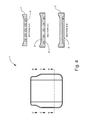
- FIG. 4 is a top view and three lateral cross-section views of an exemplary composite seat cushion of the present invention.
- FIG. 5 is a top view, a longitudinal cross-section view, and a bottom view of the exemplary seat cushion shown in FIG. 4 ;
- FIG. 6 is a cross-section of a mold assembly for fabricating a composite seat cushion of the present invention using an insert molding process.
- any references to advantages, benefits, unexpected results, or operability of the present invention are not intended as an affirmation that the invention has been previously reduced to practice or that any testing has been performed.
- use of verbs in the past tense is not intended to indicate or imply that the invention has been previously reduced to practice or that any testing has been performed.
- viscoelasticity refers to the property of having a high viscosity fluid characteristic under low stress conditions and exhibiting a substantial increase in apparent viscosity under applied stress, so that the material behaves more like a solid under such high applied stress conditions.
- a viscoelastic material may comprise one which behaves as a solid elastomer under high rate impact forces, and as a highly conformable viscous liquid at rest or when subject to a low rate of applied force.
- viscoelastic may encompass all foam products commonly referred to as “memory foam”.
- the composite seat cushion 1 comprises a molded portion 2 with a sculpted top surface 3 , and a cavity 4 in the bottom surface 5 for receiving a viscoelastic foam insert 6 .
- Molded portion 2 may be made from any type of resilient foam plastic or foam rubber product suitable for use in a seat cushion.
- the molded portion 2 is made of a polyurethane foam with minimum density of 50 kg/m3, and IFD (indentation force deflection) of 150 N (Newton) +/ ⁇ 22 N.
- IFD indentation force deflection
- the term “molded” in reference to “molded portion 2 ” is used for convenience, and intended to mean a contoured shape that may have been formed by a molding process, or by any other shaping or sculpting process.
- the viscoelastic foam insert 6 may be made from a sheet of medium density memory foam.
- the insert 6 is a 5.8 pound per cubic foot urethane viscoelastic foam product sold by KCH Enterprises, Inc. under the trade name “Confor Foam” with designation “CF-45”. Insert 6 could also be custom molded rather than formed from sheet material.
- the thickness of the viscoelastic foam insert 6 is equal to the depth of cavity 4 , and substantially less than the total thickness of the molded portion 2 .
- the thickness of insert 6 is between about 1 ⁇ 3 and 2 ⁇ 3 the total thickness of the seat cushion 1 in the vicinity of the insert 6 .
- the insert 6 is about 1.0 inches thick, while the total depth of the cushion including the insert ranges from about 1.5 to 3 inches.
- FIG. 4 is intended to depict a slightly more specific embodiment in which the amount of molded portion 2 overlying the insert 6 ranges from about 0.5 to 1.5 inches in thickness.
- the molded portion 2 preferably further comprises a series of integral pillars 11 , 12 extending the full depth of cavity 4 , and received by corresponding passages, or holes 13 , 14 in the insert 6 .
- the pillars 11 , 12 , and holes 13 , 14 may be of any cross-sectional shape, such as square, rectangular, triangular, hexagonal, and the like.
- the pillars are disposed about at least the middle to back portion of the cavity 4 to correspond with the region of the seat cushion that sees the greatest pressure load during use.
- the shape, dimensions, quantity, and distribution of pillars 11 , 12 and corresponding holes 13 , 14 may be varied as needed to produce any preferred combination of elastic and viscoelastic behavior of the seat cushion 1 .
- the pillars could comprise rows of five or three pillars instead of four as depicted.
- the pillars could comprise one relatively large elongated pillar near the center of the cushion, and one smaller elongated pillar near the back of the cushion.
- the pillars could comprise rows aligned in a front to back direction on the cushion instead of side to side, with pillars of multiple different widths within each row.
- the total pillar area, and the ratio of pillar area to insert foam area may be preferentially varied to make the composite cushion generally more elastic or more viscoelastic as dictated by a particular application.
- the pillars are arrayed in two parallel rows comprising a first row of evenly spaced large pillars 11 , and a second row of evenly spaced small pillars 12 .
- the exemplary rows run width-wise across the seat cushion, with the first row of large pillars 11 near the middle of the cavity 4 , and the second row of small pillars closer to the back of the cavity.
- the dimensions of the large pillars 11 are between about 1.5 and 2 times that of the small pillars 12 .
- the width of the large pillars is about 2 inches, and the width of the small pillars is about 1.5 inches.
- the composite seat cushion 1 may be fabricated by an insert molding process.
- a viscoelastic foam insert 6 is cut to shape, including the holes 13 , 14 , and placed on a flat surface 21 as shown.
- the flat surface 21 may comprise one half of a two part mold, or simply a suitable table top or plate adapted to serve as the bottom or base of a mold.
- a female mold 22 of the seat cushion shape is positioned over the insert 6 , and sealed against flat surface 21 , creating a cavity 23 .
- the composite cushion 1 is then formed by simply injecting or pouring liquefied foam through filler pipe 25 , filling cavity 23 and the holes 13 , 14 in insert 6 . As the foam sets, it expands and fills the entire cavity 23 , creating the molded portion 2 along with integral pillars 11 , 12 within holes 13 , 14 .
- the above insert molding process description is intended to be fundamental in nature, and by no means exclusive or comprehensive. For example it may be desirable to fill the holes 13 , 14 with liquid foam before attaching the mold 22 in order to minimize formation of air pockets in pillars 11 , 12 . Further, the liquefied foam may preferably be injected at multiple locations simultaneously, instead of through a single filler pipe as depicted for a more even fill. In addition, an optimized process may preferably incorporate venting means for allowing air and gas to escape from the mold as the liquid foam expands and tries to fill the mold cavity. Those skilled in the art will appreciate that numerous other alternative or additional steps may be employed to obtain a fully optimized molding process.
- the composite seat cushion 1 of the present invention may be formed by processes other than an insert molding process.
- the cushion 2 could be formed in a molding process completely separate from the insert 6 , and the two components subsequently bonded together to form an integral composite seat cushion 1 .
- any means-plus-function clauses are intended to cover the structures described herein as performing the recited function and not only structural equivalents, but also equivalent structures.
- a nail and a screw may not be structural equivalents in that a nail employs a cylindrical surface to secure wooden parts together, whereas a screw employs a helical surface, in the environment of fastening wooden parts, a nail and a screw may be equivalent structures.
- a construction under ⁇ 112, 6th paragraph is not intended. Additionally, it is not intended that the scope of patent protection afforded the present invention be defined by reading into any claim a limitation found herein that does not explicitly appear in the claim itself.
Abstract
Description
Claims (3)
Priority Applications (1)
| Application Number | Priority Date | Filing Date | Title |
|---|---|---|---|
| US13/407,908 US8990985B1 (en) | 2011-03-18 | 2012-02-29 | Composite seat cushion |
Applications Claiming Priority (2)
| Application Number | Priority Date | Filing Date | Title |
|---|---|---|---|
| US201161454265P | 2011-03-18 | 2011-03-18 | |
| US13/407,908 US8990985B1 (en) | 2011-03-18 | 2012-02-29 | Composite seat cushion |
Publications (1)
| Publication Number | Publication Date |
|---|---|
| US8990985B1 true US8990985B1 (en) | 2015-03-31 |
Family
ID=52707697
Family Applications (1)
| Application Number | Title | Priority Date | Filing Date |
|---|---|---|---|
| US13/407,908 Active 2032-04-06 US8990985B1 (en) | 2011-03-18 | 2012-02-29 | Composite seat cushion |
Country Status (1)
| Country | Link |
|---|---|
| US (1) | US8990985B1 (en) |
Cited By (11)
| Publication number | Priority date | Publication date | Assignee | Title |
|---|---|---|---|---|
| US20160375805A1 (en) * | 2015-06-26 | 2016-12-29 | Oshkosh Defense, Llc | Blast energy attenuating recoverable seat insert |
| JP2017030383A (en) * | 2015-07-29 | 2017-02-09 | トヨタ紡織株式会社 | Vehicle seat |
| USD782849S1 (en) * | 2015-12-28 | 2017-04-04 | Kraco Enterprises, Llc. | Seat cushion |
| USD828701S1 (en) * | 2017-02-17 | 2018-09-18 | Evolution Technologies Inc. | Set of seat cushions |
| CN108601460A (en) * | 2016-02-08 | 2018-09-28 | 积水化成品工业株式会社 | Automobile seat chair parts, vehicle seat used and their manufacturing method |
| US20180281227A1 (en) * | 2015-10-02 | 2018-10-04 | Homag Bohrsysteme Gmbh | Device for forming add-on parts |
| US20180339616A1 (en) * | 2017-05-23 | 2018-11-29 | Toyota Boshoku Kabushiki Kaisha | Vehicle seat |
| US10350851B2 (en) * | 2013-07-23 | 2019-07-16 | Anomaly Action Sports S.R.L. | Composite element for protection devices of parts of the human body |
| USD886494S1 (en) * | 2016-02-26 | 2020-06-09 | Evolution Technologies Inc. | Set of seat cushions |
| US20230002212A1 (en) * | 2017-02-15 | 2023-01-05 | Joseph T. Nilson | Composite cushions |
| US11926136B2 (en) | 2018-03-07 | 2024-03-12 | Proprietect L.P. | Composite foam article |
Citations (13)
| Publication number | Priority date | Publication date | Assignee | Title |
|---|---|---|---|---|
| US5189747A (en) | 1991-10-04 | 1993-03-02 | Canadian Posture And Seating Centre (1988) Inc. | Seat cushion |
| US20030006633A1 (en) * | 2001-05-21 | 2003-01-09 | Thermal Solutions, Inc. | Heat retentive inductive-heatable laminated matrix |
| US20030041379A1 (en) * | 2001-06-15 | 2003-03-06 | Habboub Amin K. | Body support system |
| US6585190B2 (en) | 2000-08-25 | 2003-07-01 | Skyline Industries, Inc. | Crashworthy aircraft seat |
| US20040098806A1 (en) * | 2002-11-22 | 2004-05-27 | Adolf Stender | Shaped body, in particular for a seat cushion |
| US6990701B1 (en) * | 2005-08-05 | 2006-01-31 | Vera Litvak | Sectional non-slip mattress |
| US7238730B2 (en) | 2003-06-26 | 2007-07-03 | Basf Corporation | Viscoelastic polyurethane foam |
| US20080016622A1 (en) * | 2006-07-19 | 2008-01-24 | Prust Peter C | Seat cushion |
| US7354106B2 (en) | 2004-07-22 | 2008-04-08 | Mjd Innovations, Llc | Impact-injury-minimizing seat structure and methodology |
| US20080095983A1 (en) * | 2006-10-23 | 2008-04-24 | Callsen Kevin F | Support structures and methods |
| US20100229308A1 (en) | 2008-10-03 | 2010-09-16 | Edizone, Llc | Cushions comprising core structures and related methods |
| US7996940B1 (en) * | 2008-08-27 | 2011-08-16 | University Of South Florida | Custom therapeutic seat cushion |
| US20130007962A1 (en) * | 2007-02-05 | 2013-01-10 | Kemper Support Surfaces, Inc. | Pressure relieving body support apparatus |
-
2012
- 2012-02-29 US US13/407,908 patent/US8990985B1/en active Active
Patent Citations (14)
| Publication number | Priority date | Publication date | Assignee | Title |
|---|---|---|---|---|
| US5189747A (en) | 1991-10-04 | 1993-03-02 | Canadian Posture And Seating Centre (1988) Inc. | Seat cushion |
| US6585190B2 (en) | 2000-08-25 | 2003-07-01 | Skyline Industries, Inc. | Crashworthy aircraft seat |
| US20030006633A1 (en) * | 2001-05-21 | 2003-01-09 | Thermal Solutions, Inc. | Heat retentive inductive-heatable laminated matrix |
| US20030041379A1 (en) * | 2001-06-15 | 2003-03-06 | Habboub Amin K. | Body support system |
| US20040098806A1 (en) * | 2002-11-22 | 2004-05-27 | Adolf Stender | Shaped body, in particular for a seat cushion |
| US7238730B2 (en) | 2003-06-26 | 2007-07-03 | Basf Corporation | Viscoelastic polyurethane foam |
| US7354106B2 (en) | 2004-07-22 | 2008-04-08 | Mjd Innovations, Llc | Impact-injury-minimizing seat structure and methodology |
| US6990701B1 (en) * | 2005-08-05 | 2006-01-31 | Vera Litvak | Sectional non-slip mattress |
| US20080016622A1 (en) * | 2006-07-19 | 2008-01-24 | Prust Peter C | Seat cushion |
| US20080095983A1 (en) * | 2006-10-23 | 2008-04-24 | Callsen Kevin F | Support structures and methods |
| US8668977B2 (en) * | 2006-10-23 | 2014-03-11 | Polymer Concepts, Inc. | Support structures and methods |
| US20130007962A1 (en) * | 2007-02-05 | 2013-01-10 | Kemper Support Surfaces, Inc. | Pressure relieving body support apparatus |
| US7996940B1 (en) * | 2008-08-27 | 2011-08-16 | University Of South Florida | Custom therapeutic seat cushion |
| US20100229308A1 (en) | 2008-10-03 | 2010-09-16 | Edizone, Llc | Cushions comprising core structures and related methods |
Cited By (16)
| Publication number | Priority date | Publication date | Assignee | Title |
|---|---|---|---|---|
| US10350851B2 (en) * | 2013-07-23 | 2019-07-16 | Anomaly Action Sports S.R.L. | Composite element for protection devices of parts of the human body |
| US9738186B2 (en) * | 2015-06-26 | 2017-08-22 | Oshkosh Defense, Llc | Blast energy attenuating recoverable seat insert |
| US20160375805A1 (en) * | 2015-06-26 | 2016-12-29 | Oshkosh Defense, Llc | Blast energy attenuating recoverable seat insert |
| JP2017030383A (en) * | 2015-07-29 | 2017-02-09 | トヨタ紡織株式会社 | Vehicle seat |
| US20180281227A1 (en) * | 2015-10-02 | 2018-10-04 | Homag Bohrsysteme Gmbh | Device for forming add-on parts |
| US10723038B2 (en) * | 2015-10-02 | 2020-07-28 | Homag Bohrsysteme Gmbh | Device for forming add-on parts |
| USD843134S1 (en) | 2015-12-28 | 2019-03-19 | Ca Acquisitions, Llc | Seat cushion |
| USD782849S1 (en) * | 2015-12-28 | 2017-04-04 | Kraco Enterprises, Llc. | Seat cushion |
| CN108601460A (en) * | 2016-02-08 | 2018-09-28 | 积水化成品工业株式会社 | Automobile seat chair parts, vehicle seat used and their manufacturing method |
| USD886494S1 (en) * | 2016-02-26 | 2020-06-09 | Evolution Technologies Inc. | Set of seat cushions |
| US20230002212A1 (en) * | 2017-02-15 | 2023-01-05 | Joseph T. Nilson | Composite cushions |
| US11845650B2 (en) * | 2017-02-15 | 2023-12-19 | Joseph T. Nilson | Composite cushions |
| USD828701S1 (en) * | 2017-02-17 | 2018-09-18 | Evolution Technologies Inc. | Set of seat cushions |
| US20180339616A1 (en) * | 2017-05-23 | 2018-11-29 | Toyota Boshoku Kabushiki Kaisha | Vehicle seat |
| US10471866B2 (en) * | 2017-05-23 | 2019-11-12 | Toyota Boshoku Kabushiki Kaisha | Vehicle seat |
| US11926136B2 (en) | 2018-03-07 | 2024-03-12 | Proprietect L.P. | Composite foam article |
Similar Documents
| Publication | Publication Date | Title |
|---|---|---|
| US8990985B1 (en) | Composite seat cushion | |
| EP3225459B1 (en) | Seat back for vehicle | |
| US9249274B2 (en) | Shock absorption material | |
| JP5864613B2 (en) | Vehicle seat back | |
| JP6046249B2 (en) | Cushion body | |
| KR102089918B1 (en) | Interdigitated cellular cushioning | |
| EP3011870A1 (en) | Seat cushion | |
| US9839250B2 (en) | Dynamic load-absorbing materials and articles | |
| EP3248832B1 (en) | Method for manufacturing headrest, and headrest | |
| US20090284041A1 (en) | Integral pelvic impact energy-absorbing pre-crush protective construction for vehicle door | |
| US10752137B2 (en) | Seat impact energy absorbing system | |
| US8919887B2 (en) | Elastic member made of expanded resin beads, laminated elastic structural body, and seat structure | |
| US20200238946A1 (en) | Deformable automotive noise and vibration seal for pedestrian protection | |
| US9848711B2 (en) | Mattress assembly | |
| JP2016037094A (en) | Vehicular seat | |
| EP2878914A1 (en) | Anti-trauma pad | |
| JP6046816B2 (en) | Seat cushion | |
| JP2016107801A (en) | Vehicular seat back | |
| Fitek et al. | Design of a helmet liner for improved low velocity impact protection | |
| Saunders et al. | Visco-elastic polyurethane foam as an injury mitigation device in military aircraft seating | |
| JP2016106831A (en) | Cushion body | |
| JP6075552B2 (en) | Vehicle seat cushion | |
| JP2016112222A (en) | Cushion body | |
| GB2619347A (en) | Seat assembly | |
| JP2016106834A (en) | Cushion body |
Legal Events
| Date | Code | Title | Description |
|---|---|---|---|
| AS | Assignment |
Owner name: ARMORWORKS ENTERPRISES, LLC, ARIZONA Free format text: ASSIGNMENT OF ASSIGNORS INTEREST;ASSIGNOR:WILHELM, TERRY;REEL/FRAME:028116/0336 Effective date: 20120225 |
|
| STCF | Information on status: patent grant |
Free format text: PATENTED CASE |
|
| AS | Assignment |
Owner name: THE PRIVATEBANK AND TRUST COMPANY, ILLINOIS Free format text: SECURITY INTEREST;ASSIGNOR:ARMORWORKS ENTERPRISES, INC.;REEL/FRAME:043830/0237 Effective date: 20170630 |
|
| FEPP | Fee payment procedure |
Free format text: MAINTENANCE FEE REMINDER MAILED (ORIGINAL EVENT CODE: REM.); ENTITY STATUS OF PATENT OWNER: LARGE ENTITY |
|
| FEPP | Fee payment procedure |
Free format text: SURCHARGE FOR LATE PAYMENT, LARGE ENTITY (ORIGINAL EVENT CODE: M1554); ENTITY STATUS OF PATENT OWNER: LARGE ENTITY |
|
| MAFP | Maintenance fee payment |
Free format text: PAYMENT OF MAINTENANCE FEE, 4TH YEAR, LARGE ENTITY (ORIGINAL EVENT CODE: M1551); ENTITY STATUS OF PATENT OWNER: LARGE ENTITY Year of fee payment: 4 |
|
| MAFP | Maintenance fee payment |
Free format text: PAYMENT OF MAINTENANCE FEE, 8TH YEAR, LARGE ENTITY (ORIGINAL EVENT CODE: M1552); ENTITY STATUS OF PATENT OWNER: LARGE ENTITY Year of fee payment: 8 |