US8996324B2 - Battery-state monitoring apparatus - Google Patents
Battery-state monitoring apparatus Download PDFInfo
- Publication number
- US8996324B2 US8996324B2 US13/003,326 US200913003326A US8996324B2 US 8996324 B2 US8996324 B2 US 8996324B2 US 200913003326 A US200913003326 A US 200913003326A US 8996324 B2 US8996324 B2 US 8996324B2
- Authority
- US
- United States
- Prior art keywords
- battery
- secondary battery
- state
- charge
- detecting part
- Prior art date
- Legal status (The legal status is an assumption and is not a legal conclusion. Google has not performed a legal analysis and makes no representation as to the accuracy of the status listed.)
- Expired - Fee Related, expires
Links
Images


Classifications
-
- H—ELECTRICITY
- H01—ELECTRIC ELEMENTS
- H01M—PROCESSES OR MEANS, e.g. BATTERIES, FOR THE DIRECT CONVERSION OF CHEMICAL ENERGY INTO ELECTRICAL ENERGY
- H01M10/00—Secondary cells; Manufacture thereof
- H01M10/42—Methods or arrangements for servicing or maintenance of secondary cells or secondary half-cells
- H01M10/425—Structural combination with electronic components, e.g. electronic circuits integrated to the outside of the casing
-
- G01R31/361—
-
- G—PHYSICS
- G01—MEASURING; TESTING
- G01R—MEASURING ELECTRIC VARIABLES; MEASURING MAGNETIC VARIABLES
- G01R31/00—Arrangements for testing electric properties; Arrangements for locating electric faults; Arrangements for electrical testing characterised by what is being tested not provided for elsewhere
- G01R31/36—Arrangements for testing, measuring or monitoring the electrical condition of accumulators or electric batteries, e.g. capacity or state of charge [SoC]
- G01R31/382—Arrangements for monitoring battery or accumulator variables, e.g. SoC
- G01R31/3828—Arrangements for monitoring battery or accumulator variables, e.g. SoC using current integration
-
- H—ELECTRICITY
- H01—ELECTRIC ELEMENTS
- H01M—PROCESSES OR MEANS, e.g. BATTERIES, FOR THE DIRECT CONVERSION OF CHEMICAL ENERGY INTO ELECTRICAL ENERGY
- H01M10/00—Secondary cells; Manufacture thereof
- H01M10/42—Methods or arrangements for servicing or maintenance of secondary cells or secondary half-cells
- H01M10/48—Accumulators combined with arrangements for measuring, testing or indicating the condition of cells, e.g. the level or density of the electrolyte
- H01M10/486—Accumulators combined with arrangements for measuring, testing or indicating the condition of cells, e.g. the level or density of the electrolyte for measuring temperature
-
- G—PHYSICS
- G01—MEASURING; TESTING
- G01R—MEASURING ELECTRIC VARIABLES; MEASURING MAGNETIC VARIABLES
- G01R31/00—Arrangements for testing electric properties; Arrangements for locating electric faults; Arrangements for electrical testing characterised by what is being tested not provided for elsewhere
- G01R31/36—Arrangements for testing, measuring or monitoring the electrical condition of accumulators or electric batteries, e.g. capacity or state of charge [SoC]
- G01R31/3644—Constructional arrangements
- G01R31/3648—Constructional arrangements comprising digital calculation means, e.g. for performing an algorithm
-
- Y—GENERAL TAGGING OF NEW TECHNOLOGICAL DEVELOPMENTS; GENERAL TAGGING OF CROSS-SECTIONAL TECHNOLOGIES SPANNING OVER SEVERAL SECTIONS OF THE IPC; TECHNICAL SUBJECTS COVERED BY FORMER USPC CROSS-REFERENCE ART COLLECTIONS [XRACs] AND DIGESTS
- Y02—TECHNOLOGIES OR APPLICATIONS FOR MITIGATION OR ADAPTATION AGAINST CLIMATE CHANGE
- Y02E—REDUCTION OF GREENHOUSE GAS [GHG] EMISSIONS, RELATED TO ENERGY GENERATION, TRANSMISSION OR DISTRIBUTION
- Y02E60/00—Enabling technologies; Technologies with a potential or indirect contribution to GHG emissions mitigation
- Y02E60/10—Energy storage using batteries
Definitions
- the present invention relates to a battery-state monitoring apparatus, which is provided with a state detection part for detecting a battery state of a secondary battery for supplying electric power to an electric load, the detection part using the secondary battery as a power source.
- an open circuit voltage characteristic which indicates a relationship between a state of charge and an open voltage, as one of characteristics of a secondary battery, is maintained as substantially the same open circuit voltage characteristic irrespective of deterioration of the secondary battery or changes in use condition (for example, refer to patent document 1).
- the patent document 1 discloses a battery capacity detecting method of assuming a state of charge at a time of measurement based on an open voltage measured during a charge or discharge stop period and an open circuit voltage characteristic.
- patent document 1 discloses a method of estimating a full charge capacity of a secondary battery based on states of charge before charge start and after charge end and an amount of charged electric power supplied to the secondary battery during the charge, and also a method of estimating an amount of charge remaining in the second battery after charge is ended based on a state of charge after charge end and a full charge capacity.
- Patent Document 1 Japanese Laid-Open Patent Application No. 2001-231179
- a state detecting part for detecting a battery state for example, a remaining amount of charge or a state of charge
- a secondary battery which supplies electric power to an electric load such as an electronic equipment
- the amount of charge of the secondary battery necessary to be maintained for an electric load is reduced in no small measure due to power consumption associated with the operation of the state detecting part.
- the power consumption of the state detecting part may be reduced by limiting the operation of the battery state by the state detecting part until the electric load is started up.
- the detection accuracy of the battery state goes down because the period for limiting the detecting operation for the battery state becomes long as the time until the start-up of the electric load increases.
- a battery-state monitoring apparatus comprises:
- a state detecting part detecting a battery state of said secondary battery in a detection mode to detect the battery state of said secondary battery, the state detecting part using said secondary battery as a power source,
- said battery-state monitoring apparatus includes a start-up detecting part detecting a start-up of said electric load, and
- said state detecting part waits for a detection of said battery state in a standby mode in which a power consumption is smaller than said detection mode until said start-up is detected by said start-up detecting part, and, on the other hand, said state detecting part detects, by intermittently performing a temporary return from said standby mode to said detection mode, said battery state in a return period during which said return is made.
- said state detecting part detects a remaining amount of charge of said secondary battery as said battery state.
- said state detecting part detects, during said return period, the remaining amount of charge of said secondary battery by subtracting an integration value from said remaining amount of charge detected in said detection mode prior to said return period, the integration value acquired by integrating a current consumption value of said electric load with a standby time to standby in said standby mode after the detection mode.
- the current consumption value of said electric load is stored in a memory. Additionally, if, in association with the start-up of said electric load, said start-up detecting part detects as said start-up a fluctuation in a current generated in a power supply path between said electric load and said secondary battery, said start-up detecting part may detect also the current consumption value of said electric load.
- said start-up detecting part detects as said start-up a fluctuation of a current or a voltage generated in a power supply path between said electric load and said secondary battery, and also detects the current consumption value of said electric load.
- the battery state can be detected accurately while suppressing reduction of a remaining amount of charge of the secondary battery.
- FIG. 1 is an overall structure diagram of an intelligent battery pack 100 A, which is a first embodiment of a battery-state monitoring apparatus according to the present invention
- FIG. 2 is an illustration indicating an “open voltage—state of charge” characteristic at 25° C.
- FIG. 3 is an illustration indicating a change in a current consumption of portable equipment 300 ;
- FIG. 4A is an operation flowchart of a management system in the battery pack 100 A;
- FIG. 4B is an operation flowchart of the management system in the battery pack 100 A.
- FIG. 5 is an overall structure diagram of an intelligent battery pack 100 B, which is a second embodiment of the battery-state monitoring apparatus according to the present invention.
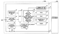
- FIG. 1 is an overall structure diagram of an intelligent battery pack 100 A, which is a first embodiment of a battery-state monitoring apparatus according to the present invention.
- the battery pack 100 A includes: a temperature detecting part 10 that detects an ambient temperature of a secondary battery 200 such as a lithium ion battery, a nickel hydrogen battery, an electric double-layer capacitor or the like; a voltage detecting part 20 that detects a voltage of the secondary battery 200 ; a current detecting part 30 that detects a charge and discharge current of the secondary battery 200 ; an AD converter (hereinafter, referred to as ADC) 40 that converts an analog voltage value, which is output from each detecting part and indicates a result of detection, into a digital value; an operation processing part 50 (for example, a microcomputer provided with a CPU 51 , a ROM 52 , a RAM 53 , etc.) that performs computation processing such as a current integration, a capacity correction, a computation of a dischargeable amount;
- ADC AD converter
- a memory 60 for example, an EEPROM or a flash memory
- characteristics data that specifies a characteristic of each of structure parts such as the secondary battery 200 or the battery pack used for the computation process
- a communication processing part 70 for example, a communication IC
- a timer 80 that manages time
- a start-up current detecting part 31 that detects a start-up current of the portable equipment 300 in accordance with a result of detection of the current detecting part 30 .
- Some or all of those structure elements may be packaged by being constituted by integrated circuits.
- the secondary battery 200 is a power source of the portable equipment 300 , and is also a power source of the ADC 40 , the operation processing part 50 , the communication processing part 70 , and the timer 80 . Moreover, with respect to the temperature detecting part 10 , the voltage detecting part 20 , the current detecting part 30 and the start-up current detecting part 31 , an electric power supplied from the secondary battery 200 may be needed according to the circuit structures of those parts. With respect to the memory 60 , the contents of the memory are maintained even when a power supply from the secondary battery 200 is interrupted.
- the temperature detecting part 10 , the voltage detecting part 20 , the current detecting part 30 , the ADC 40 and the operation processing part 50 function as a state detecting part to detect a battery state of the secondary battery 200 .
- the battery pack 100 A is a modular component which is a combination of the secondary battery 200 and a management system that manages a battery state of the secondary battery 200 .
- the battery pack 100 A is connected to the portable equipment 300 through electrode terminals (a positive-electrode terminal 1 and a negative-electrode terminal 2 ) and a communication terminal 3 .
- the positive-electrode terminal 1 is electrically connected to a positive electrode of the secondary battery 200 through a power supply path
- the negative-electrode terminal 2 is electrically connected to a negative electrode of the secondary battery 200 through a power supply path.
- the communication terminal 3 is connected to the communication processing part 70 .
- the portable equipment 300 is an electronic equipment which a person can carry, and, specifically may be a cellular phone, an information terminal apparatus such as a PDA, a mobile personal computer, etc., a camera, a game machine, a music or video player, etc.
- the battery pack 100 A may be incorporated in the portable equipment 300 or externally attached to the portable equipment 300 .
- the temperature detection part 10 detects an ambient temperature of the secondary battery 200 , and outputs the detected ambient temperature to the ADC 40 after converting it into a voltage, which can be input to the ADC 40 .
- the digital value of the battery temperature indicating the ambient temperature of the secondary battery 200 converted by the ADC 40 is transmitted to the operation processing part 50 , and used as a parameter for operation processing.
- the digital value of the battery temperature is converted into a previously determined unit by the operation processing part 50 , and is output to the portable equipment 300 through the communication processing part 70 as battery-state information indicating a battery state of the secondary battery 200 .
- the temperature detecting part 10 may be one that detects not only a temperature of the secondary battery 200 or an ambient temperature of the secondary battery but also a temperature of the battery pack 100 A or a structure part thereof if the battery pack 100 A is close to the secondary battery 200 . Additionally, in a case where the temperature detecting part 10 is constituted by an integrated circuit together with the voltage detecting part 20 , the current detecting part 30 and the ADC 40 , the temperature detecting part 10 can detect a temperature of the integrated circuit itself or an ambient temperature of the integrated circuit.
- the voltage detecting part 20 detects a voltage of the secondary battery 200 , and outputs the detected voltage to the ADC 40 after converting it into a voltage, which can be input to the ADC 40 .
- the digital value of the battery voltage indicating the voltage of the secondary battery 200 converted by the ADC 40 is transmitted to the operation processing part 50 , and used as a parameter for operation processing.
- the digital value of the battery voltage is converted into a previously determined unit by the operation processing part 50 , and is output to the portable equipment 300 through the communication processing part 70 as battery-state information indicating a battery state of the secondary battery 200 .
- the current detecting part 30 detects a charge and discharge current of the secondary battery 200 , and outputs the detected current to the ADC 40 after converting it into a voltage, which can be input to the ADC 40 .
- the current detecting part 30 is provided with a current detection resistor 30 a connected to the secondary battery 200 in series and an operation amplifier, which amplifies a voltage generated at an opposite ends of the current detecting resistor 30 a , in order to convert the charge and discharge current into a voltage by the current detection resistor 30 a and the operation amplifier.
- the operation amplifier may be provided to the ADC 40 .
- the digital value of the battery current indicating the charge and discharge current of the secondary battery 200 converted by the ADC 40 is transmitted to the operation processing part 50 , and used as a parameter for operation processing.
- the digital value of the battery current is converted into a previously determined unit by the operation processing part 50 , and is output to the portable equipment 300 through the communication processing part 70 as battery-state information indicating a battery state of the secondary battery 200
- the operation processing part 50 can compute an amount of electric power charged and discharged at the secondary battery 200 and also can compute a present amount of electric power (a remaining amount of charge) accumulated in the secondary battery 200 by integrating the current value detected by the current detecting part 30 in a charging state or a discharging state (for example, a state where a current equal to or larger than a predetermined value is consumed by an operation of the portable equipment 300 ) of the secondary battery 200 .
- a present amount of electric power accumulated in the secondary battery 200 by integrating the current value detected by the current detecting part 30 in a charging state or a discharging state (for example, a state where a current equal to or larger than a predetermined value is consumed by an operation of the portable equipment 300 ) of the secondary battery 200 .
- 2004-226393 discloses an idea in that, if a condition such as a temperature or a current is changed in a charge and discharge of a secondary battery, a charge and discharge efficiency is not changed but electric power, which is temporarily not charged or discharged, in accordance with each charge and discharge condition and an amount of such electric power is changed. According to this idea, there is no need to perform a correction process with respect to the charge and discharge efficiency.
- the operation processing part 50 may detect an ambient temperature by the temperature detecting part 10 in order to correct a charge and discharge current value of the secondary battery 200 converted by the ADC 40 based on the “charge and discharge current—temperature” characteristic.
- the “charge and discharge current—temperature” characteristic can be represented by a correction table or a correction function. Data in the correction table or a coefficient of the correction function is stored as characteristic data in the memory 60 .
- the operation processing part 50 performs a correction of the charge and discharge current value in accordance with a temperature measured by the temperature detecting part 10 .
- the operation processing part 50 may stop the integration process of the current value, or store a previously measured current consumption value of the portable equipment 300 in the memory 60 and integrate the stored value.
- the operation processing part 50 measures, when the stopped state of the portable equipment 300 continues for a predetermined time, periodically measures a voltage (open voltage) of the secondary battery 200 and computes and corrects the state of charge based on the “open voltage—state of charge” characteristics (refer to FIG. 2 ).
- the open voltage is a voltage across the electrodes, which is measured by opening the electrodes of the stable secondary battery 200 or measured with a high-impedance.
- the state of charge is a ratio of a remaining amount of charge of the secondary battery 200 represented by percentage when the full charge capacity of the secondary battery at that time is set as 100 .
- the “open voltage—state of charge” characteristic is represented by a correction table or a correction function.
- Data in the correction table or a coefficient of the correction function is stored as characteristic data in the memory 60 .
- the operation processing part 50 performs a computation and correction of the open voltage measured by the voltage detecting part 20 in accordance with the correction table or the correction function in which the character data read from the memory 60 is reflected. Additionally, if there exists a temperature characteristic in the open voltage of the secondary battery 200 , the operation processing part 50 may perform a predetermined temperature correction with respect to the open voltage.
- the operation processing part 50 can compute the state of charge of the secondary battery 200 , the operation processing part 50 cannot compute a remaining amount of charge of the secondary battery 200 unless the full charge capacity of the secondary battery 200 is not measured or estimated because the remaining amount of the secondary battery 200 is computed based on a relationship between the full charge capacity and the state of charge.
- a method of computing a full charge capacity of the secondary battery 200 there is a method of computing based on a discharge amount of the secondary battery 200 or computing based on a charge amount.
- an accurate charge current can be measured as compared to that measured based on a discharge amount, which tends to be influenced by the current consumption characteristic of the portable equipment 300 because the charge is performed with a constant voltage or a constant current if the charge is other than a pulse charge.
- the method to be used may be selected in consideration of the characteristics of the portable equipment 300 .
- the condition at which an accurate full charge capacity can be measured is a case where a charge is performed continuously for a period from a state where a remaining amount of charge is zero until a fully-charged state is reached, and the current value integrated during the charge period is the full charge capacity.
- a charge is rarely performed, and, normally, a charge is performed from a state where a certain remaining amount of charge is present.
- the operation processing part 50 computes the full charge capacity of the secondary battery 200 based on a battery voltage at a time immediately before a start of a charge and a battery voltage at a time a predetermined time has passed after an end of the charge. That is, the operation processing part 50 computes a state of charge at the time immediately before the start of the charge based on the battery voltage at the time immediately before the start of the charge and the “open voltage—state of charge” characteristic (refer to FIG.
- a function of a management system of a battery system of the secondary battery 200 such as a battery remaining amount management, a deterioration diagnosis, a history management of abnormality detection, etc., is added to the battery pack 100 A used by the portable equipment 300 , an electric power is consumed to achieve the function to no small extent, which is a cause of reducing an amount of charge of the secondary battery 200 .
- the management system itself shifting to a standby mode in which a power consumption is lower than that of a normal state in association with the management system of the battery pack 100 A shifting to an operation mode in which the portable equipment 300 consumes a smaller electric power than that in a normal operation mode, a consumption of energy accumulated in the secondary battery 200 can be suppressed effectively.
- FIG. 3 is an illustration indicating a change in a current consumption of the portable equipment 300 .
- the portable equipment 300 has a function which operates in a low power consumption mode in which a power consumption is lower than that in a normal operation mode.
- the portable equipment 300 shifts from the normal operation mode to the low power consumption mode when a condition to shift to the low power consumption mode is established in the normal operation mode. Additionally, the portable equipment 300 shifts from the low power consumption mode to the normal operation mode when a condition to shift to the normal operation mode is established in the low power consumption mode.
- the portable equipment 300 is a cellular phone
- the operation processing part 50 changes its own operation mode in response to a change in the operation mode of the portable equipment 300 .
- the operation processing part 50 monitors a current consumption value of the portable equipment 300 through the ADC 40 so that if a current value, at which it is regarded that the portable equipment 300 shifted to the low power consumption mode, is detected for a fixed period, the operation processing part 50 determines that the portable equipment 300 has shifted to the low power consumption mode and shifts the operation mode of the operation processing part 50 itself from a detection mode, in which a detecting operation of a battery state of the secondary battery 200 is performed, to a standby mode, in which a power consumption is lower than that of the detection mode.
- the operation processing part 50 stops the detecting operation of the secondary battery 200 or delays the cycle of the detecting operation.
- the power consumption of the operation processing part 50 and the ADC 40 can be reduced, and the temperature detection part 10 , the voltage detecting part 20 and the current detecting part 30 can be operated to a required minimum.
- the operation processing part 50 operates in the standby mode, in which the detecting operation of a battery state of the secondary battery 200 is limited, until a start-up of the portable equipment 300 is detected by the start-up current detecting part 31 (refer to FIG. 1 ). Further, the operation processing part 50 performs, at a predetermined return period, a temporary returning operation from the standby mode to the detection mode until a start-up of the portable equipment 300 is detected by the start-up current detecting part 31 . The return period is managed by the timer 80 .
- the start-up current detecting part 31 detects a start-up of the portable equipment 300 from the low power consumption mode to the normal operation mode when the operation processing part 50 is in the standby mode. That is, the start-up current detecting part 31 is not limited in its operation even when it is in the standby mode.
- the start-up current detecting part 31 detects a start-up of the portable equipment 300 by the start-up current, which is generated in association with the start-up of the portable equipment 300 being detected by the detection resistor 30 a .
- the start-up current detecting part 31 sends a return signal (interrupt signal) to the CPU 51 when a current exceeds a current threshold value, which is needed to detect a start-up current.
- the CPU 51 Upon reception of the return signal, the CPU 51 shifts from the standby mode to the detection mode, and restarts the detecting operation of the secondary battery 200 .
- the current threshold value for detecting the start-up current may be set to, for example, 200 mA. Because the start-up current rises while the current value thereof fluctuates, hysteresis may be provided to the current threshold value for detecting the start-up of the portable equipment 300 .
- the operation processing part 50 detects a battery state of the secondary battery 200 , such as a remaining amount of charge, a state of charge or an occurrence of abnormality, by detecting a temperature, a voltage and a current of the secondary battery 200 during the return period where the mode is temporarily shifted from the standby mode to the detection mode.
- the operation processing part 50 shifts from the detection mode to the standby mode after the temporary detection of the battery state of the secondary battery 200 is completed.
- the time period of the operation processing part 50 being set in the standby mode becomes long due to elongation of the period of the low power consumption mode of the portable equipment 300 by spontaneously and temporarily returning to the detecting mode (due to the start-up of the portable equipment 300 not being detected)
- the state where the detecting operation of the battery state is not performed is prevented from being continued for a long time, which suppresses deterioration in the accuracy of detection of the battery state.
- the operation processing part 50 performs, in a temporary return period, a first remaining amount correction process for computing a remaining amount of charge in the present return period by subtracting an amount of charge corresponding to a value, which is a multiplication of a current consumed by the portable equipment 300 in the low power consumption mode and a standby time during which the operation processing part 50 operates in the standby mode, from a remaining amount of charge computed in the detection mode. That is, the multiplication value, which is acquired by multiplying the current consumption value of the portable equipment 300 in the low power consumption mode by the standby time during which the operation processing part 50 is in the standby mode between a last return period and a present return period, is subtracted from an amount of change computed in the detection mode during the last return period.
- the remaining amount of charge in the first return period is computed by subtracting a multiplication value, which is acquired by multiplying the current consumption value consumed by the portable equipment in the low power consumption mode by the period from a time at which it shifts to the low power consumption mode to the time at which the first return period begins.
- the current value consumed by the portable equipment 300 in the low power consumption mode is previously stored in the memory 60 . Because the current consumption in the low power consumption mode is substantially constant as illustrated in FIG. 3 , the current value can be previously stored in the memory 60 with a small memory capacity. If the type or specification of the portable equipment 300 is changed, it can deal with such a change by rewriting the stored information in the memory 60 .
- the current consumption value may not be previously stored in the memory 60 but may be actually measured. Because the start-up current detecting part 31 measures a current in the standby mode and the detection accuracy of the current consumption in the low power consumption mode of the portable equipment 300 is raised by using the actually measured value, the detection accuracy of the battery state such as a remaining amount of charge or the like can be raised.
- the operation processing part 50 performs, during a temporary return period, a second remaining amount correction process to compute a remaining amount of charge at the present return period by detecting or computing an ambient temperature, an open voltage, a state of charge, a full charge capacity, a degree of deterioration, etc., of the secondary battery 200 by using the characteristic illustrated in FIG. 2 as mentioned above.
- a second remaining amount correction process to compute a remaining amount of charge at the present return period by detecting or computing an ambient temperature, an open voltage, a state of charge, a full charge capacity, a degree of deterioration, etc.
- the return period of the second remaining amount correction process is set longer than the return period of the first remaining amount correction process (for example, the return period of the first remaining amount correction period is set to a value between 1 second to 1 hour, and the return period of the second remaining amount correction process is set to a value between 1 hour to 3 hours). That is, the first remaining amount correction process bears a short-period correction of the result of computation of a remaining amount of charge, and the second remaining amount correction process bears a long-period correction of the result of computation of a remaining amount of charge.
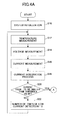
- FIGS. 4A and 4B are operation flowcharts of the management system in the battery pack 100 A.
- the management system operates with the operation processing part 50 serving as a main part.
- the operation processing part 50 performs a temperature measurement by the temperature detecting part 10 (step 12 ), a voltage measurement by the voltage detecting part 20 (step 14 ), and a current measurement by the current detecting part 30 (step 16 ). Additionally, the operation processing part 50 performs a current integration process (step 18 ).
- the operation processing part 50 judges whether the current consumption of the portable equipment 300 is equal to or smaller than predetermined current threshold value based on these measurement results and processing results (step 20 ). If it is not equal to or smaller than the predetermined current threshold value, the operation processing part 50 assumes that the portable equipment 300 is in the normal operation mode and a flag of the number of times of low current detection is set to zero (step 22 ) to repeat the operation of step 12 and the subsequent steps. On the other hand, if it is equal to or smaller than the predetermined current threshold value, the flag of the number of times of low current detection is incremented (step 24 ).
- the operation processing part 50 judges whether the value of the flag of the number of times of low current detection is equal to or larger than a predetermined threshold value for number of times (step 26 ). If it is not equal to or larger than the number of times threshold value, it is regarded that the number of times of low current detection is less than the threshold value for number of times and the operation of step 12 and subsequent steps is repeated. If it is equal to or larger than the threshold value for number of times, it is judged that the portable equipment 300 shifted to the low power consumption mode and the setting mode of its own is shifted from the detection mode to the standby mode (step 28 ).
- a period from a detection of reduction in the current consumption of the portable equipment 300 until the setting mode of the operation processing part 50 is shifted from the detection mode to the standby mode is maintained to be equal to or longer than a fixed time.
- the operation processing part 50 waits for interrupt of a return signal from the start-up current detecting part 31 in the standby mode (step 30 ). If a cause of interrupt is not a detection of a start-up current, the process proceeds to step 34 . That is, if a cause of the interrupt is not a spontaneous return responding to the above-mentioned return period, the operation processing part 50 performs the above-mentioned first or second remaining amount correction process (step 34 ) without changing the flag value of the number of times of low current detection in order to repeat the operation of step 12 and subsequent steps.
- the operation processing part 50 sets the flag of the number of times of low current detection is set to zero (step 36 ) and performs the above-mentioned first or second remaining amount correction process (step 34 ) in order to repeat the operation of step 12 and subsequent steps.
- the operation processing part 50 and the ADC 40 which are main parts of the management system, in the detection mode by providing the start-up current detecting part 31 , which can be configured by a simple circuit to detect a start-up current, and a consumption of a remaining amount of charge of the secondary battery 200 by the management system, which manages the battery status of the secondary battery 200 .
- the battery state can be detected, even when the portable equipment 300 is not started-up, by returning intermittently from the standby mode to the detection mode, the detection accuracy is prevented from being deteriorated due to nondetection of the battery state while taking an advantage of the reduction in the power consumption by setting to the standby mode.
- FIG. 5 is an overall structure diagram of an intelligent battery pack 100 B, which is a second embodiment of the battery state monitoring apparatus according to the present invention. Descriptions of parts which are the same as parts of the battery pack 100 A will be omitted.
- the battery pack 100 B performs a detection of a start-up of the portable equipment 300 not by a detection of a start-up current as in the battery pack 100 A, but a detection of a start-up voltage. If a relatively large start-up current flows in the portable equipment 300 , a voltage drop corresponding to “multiplication value of the start-up current and an internal resistance” is generated because there is an internal resistance in the secondary battery 200 . Thus, it can be determined that the portable equipment 300 was started-up when the start-up voltage detecting part 21 detects the voltage drop.
- the start-up voltage detecting part 21 sends a return signal (interrupt signal) to the CPU 51 when a current causing a voltage to exceed a voltage threshold value, which is necessary for detecting a start-up voltage, flows.
- a return signal interrupt signal
- the CPU 51 shifts from the standby mode to the detection mode and restarts the detecting operation of the secondary battery 200 .
- the operation processing part 50 may perform a detection of a start-up of the portable equipment 300 by receiving a start-up signal from the portable equipment 300 through the communication processing part 70 .
- the portable equipment 300 outputs the start-up signal, which represents that the portable equipment itself has been started-up, and the operation processing part 50 judges whether the portable equipment 300 has been started-up based on the start-up signal.
- the portable equipment 300 outputs the start-up signal of an H-level when it is in the normal mode, and outputs the start-up signal of an L-level when it is in the low power consumption mode.
Abstract
Description
FCC=Q/[(SOC2−SOC1)/100} (1)
where the full charge capacity is FCC [mAh], the state of charge at the time immediately before a start of a charge is SOC1 [%], the state of charge at a time a predetermined time has passed after an end of the charge is SOC2 [%], and an amount of electric power charged during a charge period from the charge start time to the charge end time. It should be noted that if SOC1 and SOC2 are temperature-corrected, more accurate value can be computed. Moreover, by using the battery voltage at the time a predetermined time has passed after the charge end time, the accuracy of the computation result can be raised by reflecting a battery voltage more stable than that of the charge end time in the computation.
SOH=RFCC/AFCC×100 (2)
where an initial full charge capacity is AFCC and a full charge capacity at an arbitrary time is RFCC.
-
- 10 temperature detecting part
- 20 voltage detecting part
- 21 start-up voltage detecting part
- 30 current detecting part
- 31 start-up current detecting part
- 40 ADC
- 50 operation processing part
- 60 memory
- 70 communication processing part
- 80 timer
- 100A, 100B battery pack
- 200 secondary battery
- 300 portable equipment
Claims (4)
Applications Claiming Priority (3)
| Application Number | Priority Date | Filing Date | Title |
|---|---|---|---|
| JP2008-181923 | 2008-07-11 | ||
| JP2008181923A JP5561916B2 (en) | 2008-07-11 | 2008-07-11 | Battery status monitoring device |
| PCT/JP2009/062355 WO2010004984A1 (en) | 2008-07-11 | 2009-07-07 | Battery state monitoring device |
Publications (2)
| Publication Number | Publication Date |
|---|---|
| US20110119005A1 US20110119005A1 (en) | 2011-05-19 |
| US8996324B2 true US8996324B2 (en) | 2015-03-31 |
Family
ID=41507097
Family Applications (1)
| Application Number | Title | Priority Date | Filing Date |
|---|---|---|---|
| US13/003,326 Expired - Fee Related US8996324B2 (en) | 2008-07-11 | 2009-07-07 | Battery-state monitoring apparatus |
Country Status (4)
| Country | Link |
|---|---|
| US (1) | US8996324B2 (en) |
| JP (1) | JP5561916B2 (en) |
| CN (1) | CN102084261B (en) |
| WO (1) | WO2010004984A1 (en) |
Cited By (1)
| Publication number | Priority date | Publication date | Assignee | Title |
|---|---|---|---|---|
| US11126804B2 (en) | 2018-08-06 | 2021-09-21 | Techtronic Cordless Gp | Systems and methods for selectively enabling the operation of a device |
Families Citing this family (54)
| Publication number | Priority date | Publication date | Assignee | Title |
|---|---|---|---|---|
| US6820206B1 (en) * | 2001-11-20 | 2004-11-16 | Palmone, Inc. | Power sharing between portable computer system and peripheral device |
| JP5010657B2 (en) * | 2009-09-18 | 2012-08-29 | 三菱重工業株式会社 | Battery system |
| US10422824B1 (en) * | 2010-02-19 | 2019-09-24 | Nikola Llc | System and method for efficient adaptive joint estimation of battery cell state-of-charge, resistance, and available energy |
| US9203489B2 (en) | 2010-05-05 | 2015-12-01 | Google Technology Holdings LLC | Method and precoder information feedback in multi-antenna wireless communication systems |
| US8990038B2 (en) * | 2010-06-16 | 2015-03-24 | Kenneth L. Staton | Method and apparatus for monitoring battery life |
| JP5174111B2 (en) * | 2010-09-27 | 2013-04-03 | 三菱重工業株式会社 | Battery system |
| JP5527895B2 (en) | 2010-11-18 | 2014-06-25 | パナソニック株式会社 | Secondary battery control device and control method |
| KR101223735B1 (en) * | 2011-04-07 | 2013-01-21 | 로베르트 보쉬 게엠베하 | Battery management system and control method thereof |
| CN102279369B (en) * | 2011-07-21 | 2017-02-15 | 深圳市核达中远通电源技术有限公司 | Intelligent remote online storage battery detection method and system |
| WO2013018143A1 (en) * | 2011-08-03 | 2013-02-07 | トヨタ自動車株式会社 | Device for estimating state of deterioration of secondary battery and method for estimating state of deterioration |
| JP5866987B2 (en) * | 2011-11-10 | 2016-02-24 | 日産自動車株式会社 | Secondary battery control device and SOC detection method |
| CN102496750B (en) | 2011-12-20 | 2014-10-08 | 华为技术有限公司 | Battery |
| US9231268B2 (en) * | 2011-12-20 | 2016-01-05 | United Technologies Corporation | Flow battery system with standby mode |
| WO2013177396A2 (en) * | 2012-05-24 | 2013-11-28 | Heartware, Inc. | Low-power battery pack with safety system |
| WO2013187581A1 (en) * | 2012-06-13 | 2013-12-19 | 주식회사 엘지화학 | Apparatus and method for estimating state of charge state of charge of secondary cell including mixed cathode material |
| FR2994339B1 (en) * | 2012-08-06 | 2014-09-12 | Commissariat Energie Atomique | METHOD FOR MANAGING AND DIAGNOSING A BATTERY |
| US9419457B2 (en) | 2012-09-04 | 2016-08-16 | Google Technology Holdings LLC | Method and device with enhanced battery capacity savings |
| US9356461B2 (en) | 2012-09-25 | 2016-05-31 | Google Technology Holdings, LLC | Methods and systems for rapid wireless charging where the low state of charge (SOC) temperature dependent charging current and low SOC temperature limit are higher than the high SOC temperature dependent charging current and high SOC temperature limit |
| DE102012111086B4 (en) * | 2012-11-19 | 2019-01-03 | Infineon Technologies Ag | Methods and apparatus for determining a state of charge |
| US9813262B2 (en) | 2012-12-03 | 2017-11-07 | Google Technology Holdings LLC | Method and apparatus for selectively transmitting data using spatial diversity |
| US9591508B2 (en) | 2012-12-20 | 2017-03-07 | Google Technology Holdings LLC | Methods and apparatus for transmitting data between different peer-to-peer communication groups |
| US9979531B2 (en) | 2013-01-03 | 2018-05-22 | Google Technology Holdings LLC | Method and apparatus for tuning a communication device for multi band operation |
| JP6075109B2 (en) * | 2013-02-21 | 2017-02-08 | 日産自動車株式会社 | Battery capacity presentation device, battery capacity presentation system, information center, and battery capacity presentation method |
| US10044214B2 (en) * | 2013-03-08 | 2018-08-07 | Texas Instruments Incorporated | Battery charger |
| US10229697B2 (en) | 2013-03-12 | 2019-03-12 | Google Technology Holdings LLC | Apparatus and method for beamforming to obtain voice and noise signals |
| US9491706B2 (en) | 2013-03-13 | 2016-11-08 | Google Technology Holdings LLC | Reduced-power transmitting from a communications device |
| US9386542B2 (en) | 2013-09-19 | 2016-07-05 | Google Technology Holdings, LLC | Method and apparatus for estimating transmit power of a wireless device |
| JP6066890B2 (en) * | 2013-11-25 | 2017-01-25 | 三菱重工業株式会社 | Degradation amount estimation device, degradation amount estimation method, and program |
| JP6151163B2 (en) * | 2013-12-06 | 2017-06-21 | 株式会社東芝 | Battery state calculation device and battery state calculation method |
| US9596653B2 (en) | 2013-12-16 | 2017-03-14 | Google Technology Holdings LLC | Remedying power drain via a coverage map |
| US9549290B2 (en) | 2013-12-19 | 2017-01-17 | Google Technology Holdings LLC | Method and apparatus for determining direction information for a wireless device |
| CN103818266B (en) * | 2014-03-19 | 2015-11-11 | 苏州易美新思新能源科技有限公司 | A kind of energy-storage battery management control algorithm |
| US9491007B2 (en) | 2014-04-28 | 2016-11-08 | Google Technology Holdings LLC | Apparatus and method for antenna matching |
| US9865897B2 (en) | 2014-06-02 | 2018-01-09 | Google Llc | Stacked electrochemical cell with increased energy density |
| US9478847B2 (en) | 2014-06-02 | 2016-10-25 | Google Technology Holdings LLC | Antenna system and method of assembly for a wearable electronic device |
| US9438293B2 (en) | 2014-08-05 | 2016-09-06 | Google Technology Holdings LLC | Tunable circuit elements for dynamic, per element power |
| US9472965B2 (en) | 2014-09-08 | 2016-10-18 | Google Technology Holdings LLC | Battery cycle life through smart overnight charging |
| JP6490414B2 (en) * | 2014-12-05 | 2019-03-27 | 古河電気工業株式会社 | Secondary battery state detection device and secondary battery state detection method |
| JP6323327B2 (en) * | 2014-12-18 | 2018-05-16 | 株式会社デンソー | Battery monitoring device |
| JP6323326B2 (en) * | 2014-12-18 | 2018-05-16 | 株式会社デンソー | Battery monitoring device |
| US10205335B2 (en) * | 2015-02-24 | 2019-02-12 | Kabushiki Kaisha Toshiba | Storage battery management device, method, and computer program product |
| JP6425093B2 (en) * | 2015-03-03 | 2018-11-21 | 株式会社オートネットワーク技術研究所 | Storage pack |
| WO2016152516A1 (en) * | 2015-03-25 | 2016-09-29 | 株式会社Gsユアサ | Electricity storage element monitoring device, electricity storage device, and electricity storage element monitoring method |
| CN106155259A (en) * | 2015-04-21 | 2016-11-23 | 联想(北京)有限公司 | A kind of power control method and device |
| CN107851858B (en) * | 2015-07-06 | 2020-10-09 | 三洋电机株式会社 | Battery pack and discharge control method for secondary battery |
| US10749362B2 (en) * | 2015-08-28 | 2020-08-18 | Panasonic Intellectual Property Management Co., Ltd. | Method for server apparatus to detect abnormality in electrical-power storage device |
| JP6830318B2 (en) * | 2016-01-15 | 2021-02-17 | 株式会社Gsユアサ | Power storage element management device, power storage element module, vehicle and power storage element management method |
| CN108663626A (en) * | 2017-08-16 | 2018-10-16 | 众泰新能源汽车有限公司 | A kind of prediction technique of power battery SOH |
| JP6844511B2 (en) * | 2017-11-21 | 2021-03-17 | セイコーエプソン株式会社 | Portable information processing equipment, integrated circuits, and battery packs |
| US11056698B2 (en) | 2018-08-02 | 2021-07-06 | Raytheon Technologies Corporation | Redox flow battery with electrolyte balancing and compatibility enabling features |
| JP7055573B2 (en) * | 2018-09-13 | 2022-04-18 | アルパイン株式会社 | Electronic devices, electronic device processing methods and electronic device processing programs |
| CN110854978A (en) * | 2019-11-25 | 2020-02-28 | 陈正芬 | Charger with zero standby power consumption |
| CN112526363B (en) * | 2020-11-25 | 2021-10-22 | 深圳易马达科技有限公司 | Detection method and detection device for equipment working time, terminal and storage medium |
| US11271226B1 (en) | 2020-12-11 | 2022-03-08 | Raytheon Technologies Corporation | Redox flow battery with improved efficiency |
Citations (11)
| Publication number | Priority date | Publication date | Assignee | Title |
|---|---|---|---|---|
| US4163186A (en) * | 1977-10-06 | 1979-07-31 | Haley William E | Battery state-of-charge indicator |
| US4965738A (en) | 1988-05-03 | 1990-10-23 | Anton/Bauer, Inc. | Intelligent battery system |
| JPH03217007A (en) | 1990-01-11 | 1991-09-24 | Universal Instr Corp | High frequency number thermo-driver using one winding secondary side transformer |
| JPH03285522A (en) | 1990-03-31 | 1991-12-16 | Anton Bauer Inc | Battery system |
| JPH09247852A (en) | 1996-03-08 | 1997-09-19 | Sony Corp | Battery pack and controlling method of battery |
| WO2001017053A1 (en) | 1999-09-01 | 2001-03-08 | Fujitsu Limited | Battery management circuit |
| US6212410B1 (en) | 1997-02-24 | 2001-04-03 | Nec Corporation | Portable telephone apparatus with security function |
| JP2001231179A (en) | 2000-02-15 | 2001-08-24 | Hitachi Maxell Ltd | Method and apparatus for detecting battery capacity and battery pack |
| US20040204174A1 (en) * | 2002-10-29 | 2004-10-14 | Goran Pehrsson | Method for using system information from a wireless network to predict current consumption in different modes of a mobile telephone |
| US20070170892A1 (en) * | 2004-03-25 | 2007-07-26 | Mitsunori Ishii | Method and apparatus for estimating remaining capacity of electric storage |
| US20080111520A1 (en) * | 2006-11-14 | 2008-05-15 | Sony Corporation | Battery pack |
Family Cites Families (6)
| Publication number | Priority date | Publication date | Assignee | Title |
|---|---|---|---|---|
| JPH07143741A (en) * | 1993-11-15 | 1995-06-02 | Hitachi Ltd | Switching power supply |
| US6522361B2 (en) * | 1996-03-08 | 2003-02-18 | Sony Corporation | Electronic apparatus having the function of displaying the battery residual quantity and method for displaying the battery residual quantity |
| JP2001218461A (en) * | 2000-01-31 | 2001-08-10 | Sony Corp | Switching power supply unit |
| JP3976645B2 (en) * | 2002-08-23 | 2007-09-19 | 矢崎総業株式会社 | Battery charge state measuring method and apparatus |
| JP4797454B2 (en) * | 2005-06-09 | 2011-10-19 | 三菱電機株式会社 | Battery remaining capacity detection device |
| JP4984527B2 (en) * | 2005-12-27 | 2012-07-25 | トヨタ自動車株式会社 | Secondary battery charge state estimation device and charge state estimation method |
-
2008
- 2008-07-11 JP JP2008181923A patent/JP5561916B2/en active Active
-
2009
- 2009-07-07 WO PCT/JP2009/062355 patent/WO2010004984A1/en active Application Filing
- 2009-07-07 CN CN200980126388.7A patent/CN102084261B/en active Active
- 2009-07-07 US US13/003,326 patent/US8996324B2/en not_active Expired - Fee Related
Patent Citations (12)
| Publication number | Priority date | Publication date | Assignee | Title |
|---|---|---|---|---|
| US4163186A (en) * | 1977-10-06 | 1979-07-31 | Haley William E | Battery state-of-charge indicator |
| US4965738A (en) | 1988-05-03 | 1990-10-23 | Anton/Bauer, Inc. | Intelligent battery system |
| JPH03217007A (en) | 1990-01-11 | 1991-09-24 | Universal Instr Corp | High frequency number thermo-driver using one winding secondary side transformer |
| JPH03285522A (en) | 1990-03-31 | 1991-12-16 | Anton Bauer Inc | Battery system |
| JPH09247852A (en) | 1996-03-08 | 1997-09-19 | Sony Corp | Battery pack and controlling method of battery |
| US6212410B1 (en) | 1997-02-24 | 2001-04-03 | Nec Corporation | Portable telephone apparatus with security function |
| WO2001017053A1 (en) | 1999-09-01 | 2001-03-08 | Fujitsu Limited | Battery management circuit |
| JP2001231179A (en) | 2000-02-15 | 2001-08-24 | Hitachi Maxell Ltd | Method and apparatus for detecting battery capacity and battery pack |
| US20040204174A1 (en) * | 2002-10-29 | 2004-10-14 | Goran Pehrsson | Method for using system information from a wireless network to predict current consumption in different modes of a mobile telephone |
| US20070170892A1 (en) * | 2004-03-25 | 2007-07-26 | Mitsunori Ishii | Method and apparatus for estimating remaining capacity of electric storage |
| US20080111520A1 (en) * | 2006-11-14 | 2008-05-15 | Sony Corporation | Battery pack |
| JP2008125268A (en) | 2006-11-14 | 2008-05-29 | Sony Corp | Battery pack |
Non-Patent Citations (1)
| Title |
|---|
| Chinese Office Action mailed Nov. 5, 2012 with English translation. |
Cited By (1)
| Publication number | Priority date | Publication date | Assignee | Title |
|---|---|---|---|---|
| US11126804B2 (en) | 2018-08-06 | 2021-09-21 | Techtronic Cordless Gp | Systems and methods for selectively enabling the operation of a device |
Also Published As
| Publication number | Publication date |
|---|---|
| US20110119005A1 (en) | 2011-05-19 |
| JP5561916B2 (en) | 2014-07-30 |
| JP2010019757A (en) | 2010-01-28 |
| CN102084261A (en) | 2011-06-01 |
| WO2010004984A1 (en) | 2010-01-14 |
| CN102084261B (en) | 2015-03-25 |
Similar Documents
| Publication | Publication Date | Title |
|---|---|---|
| US8996324B2 (en) | Battery-state monitoring apparatus | |
| US20110112782A1 (en) | Battery status detection device | |
| US8749204B2 (en) | Battery condition detector, battery pack including same, and battery condition detecting method | |
| JP5368038B2 (en) | Battery state detection device and battery pack incorporating the same | |
| JP5439126B2 (en) | Status detector for power supply | |
| US8150642B2 (en) | Secondary battery deterioration judging device and backup power supply | |
| US10845417B2 (en) | Battery state estimation device, battery control device, battery system, battery state estimation method | |
| US8203305B1 (en) | Enhanced voltage-based fuel gauges and methods | |
| EP2023154A2 (en) | Battery status detecting method, battery status detecting apparatus, and expression deriving method | |
| WO2011048471A1 (en) | Power supply apparatus | |
| CN109616704B (en) | Device for battery management and method for managing charging of a battery | |
| JP2010085243A (en) | Method of detecting full charge capacity of backup battery | |
| JP2012253975A (en) | Charging/discharging control method for alkali storage battery, and charging/discharging system | |
| JP4764971B2 (en) | Battery level measuring device | |
| JP4016881B2 (en) | Battery level measuring device | |
| JP2005312239A (en) | Charging method for secondary battery and battery pack | |
| JP3551084B2 (en) | Secondary battery state management method and battery pack using this method | |
| JP4255755B2 (en) | Secondary battery remaining capacity calculation device and remaining capacity calculation method thereof | |
| JP4660367B2 (en) | Rechargeable battery remaining capacity detection method | |
| JP3743439B2 (en) | Secondary battery deterioration judgment circuit | |
| JP2004361312A (en) | Remaining capacity arithmetic unit and remaining capacity computing method of secondary battery |
Legal Events
| Date | Code | Title | Description |
|---|---|---|---|
| AS | Assignment |
Owner name: NTT DOCOMO, INC., JAPAN Free format text: ASSIGNMENT OF ASSIGNORS INTEREST;ASSIGNORS:MAJIMA, YOSHIHIDE;TAKAHASHI, MITSUHIRO;TAKENO, KAZUHIKO;AND OTHERS;REEL/FRAME:025606/0745 Effective date: 20110105 Owner name: MITSUMI ELECTRIC CO., LTD., JAPAN Free format text: ASSIGNMENT OF ASSIGNORS INTEREST;ASSIGNORS:MAJIMA, YOSHIHIDE;TAKAHASHI, MITSUHIRO;TAKENO, KAZUHIKO;AND OTHERS;REEL/FRAME:025606/0745 Effective date: 20110105 |
|
| STCF | Information on status: patent grant |
Free format text: PATENTED CASE |
|
| FEPP | Fee payment procedure |
Free format text: MAINTENANCE FEE REMINDER MAILED (ORIGINAL EVENT CODE: REM.); ENTITY STATUS OF PATENT OWNER: LARGE ENTITY |
|
| LAPS | Lapse for failure to pay maintenance fees |
Free format text: PATENT EXPIRED FOR FAILURE TO PAY MAINTENANCE FEES (ORIGINAL EVENT CODE: EXP.); ENTITY STATUS OF PATENT OWNER: LARGE ENTITY |
|
| STCH | Information on status: patent discontinuation |
Free format text: PATENT EXPIRED DUE TO NONPAYMENT OF MAINTENANCE FEES UNDER 37 CFR 1.362 |
|
| FP | Lapsed due to failure to pay maintenance fee |
Effective date: 20190331 |