US9007664B2 - Identification reader - Google Patents
Identification reader Download PDFInfo
- Publication number
- US9007664B2 US9007664B2 US13/866,817 US201313866817A US9007664B2 US 9007664 B2 US9007664 B2 US 9007664B2 US 201313866817 A US201313866817 A US 201313866817A US 9007664 B2 US9007664 B2 US 9007664B2
- Authority
- US
- United States
- Prior art keywords
- reader
- identification
- infrared
- sensor
- document
- Prior art date
- Legal status (The legal status is an assumption and is not a legal conclusion. Google has not performed a legal analysis and makes no representation as to the accuracy of the status listed.)
- Active
Links
- 238000000034 method Methods 0.000 claims description 34
- 238000001514 detection method Methods 0.000 claims description 25
- 230000007246 mechanism Effects 0.000 claims description 8
- 238000005070 sampling Methods 0.000 claims description 8
- 238000012544 monitoring process Methods 0.000 claims description 7
- 230000009471 action Effects 0.000 claims description 5
- 230000000903 blocking effect Effects 0.000 claims description 4
- 230000000694 effects Effects 0.000 abstract description 2
- 238000013461 design Methods 0.000 description 30
- 230000008569 process Effects 0.000 description 16
- 230000003287 optical effect Effects 0.000 description 15
- 238000003780 insertion Methods 0.000 description 11
- 230000037431 insertion Effects 0.000 description 11
- 230000014759 maintenance of location Effects 0.000 description 9
- 230000006835 compression Effects 0.000 description 8
- 238000007906 compression Methods 0.000 description 8
- 238000004519 manufacturing process Methods 0.000 description 8
- 238000002347 injection Methods 0.000 description 7
- 239000007924 injection Substances 0.000 description 7
- 238000003384 imaging method Methods 0.000 description 6
- 239000000463 material Substances 0.000 description 6
- 230000008901 benefit Effects 0.000 description 4
- 239000003795 chemical substances by application Substances 0.000 description 4
- 230000013011 mating Effects 0.000 description 4
- 238000004458 analytical method Methods 0.000 description 3
- 238000005516 engineering process Methods 0.000 description 3
- 239000000243 solution Substances 0.000 description 3
- 238000013519 translation Methods 0.000 description 3
- 230000005540 biological transmission Effects 0.000 description 2
- 238000012937 correction Methods 0.000 description 2
- 230000009977 dual effect Effects 0.000 description 2
- 229920001971 elastomer Polymers 0.000 description 2
- 230000007613 environmental effect Effects 0.000 description 2
- 238000007667 floating Methods 0.000 description 2
- 239000011521 glass Substances 0.000 description 2
- 238000010348 incorporation Methods 0.000 description 2
- 238000000465 moulding Methods 0.000 description 2
- 239000004033 plastic Substances 0.000 description 2
- 238000012546 transfer Methods 0.000 description 2
- 230000008859 change Effects 0.000 description 1
- 238000010276 construction Methods 0.000 description 1
- 239000004035 construction material Substances 0.000 description 1
- 230000001934 delay Effects 0.000 description 1
- 230000009365 direct transmission Effects 0.000 description 1
- 238000006073 displacement reaction Methods 0.000 description 1
- 239000000806 elastomer Substances 0.000 description 1
- 238000005286 illumination Methods 0.000 description 1
- 239000012528 membrane Substances 0.000 description 1
- 239000000203 mixture Substances 0.000 description 1
- 239000002991 molded plastic Substances 0.000 description 1
- 238000012545 processing Methods 0.000 description 1
- 230000000717 retained effect Effects 0.000 description 1
- 210000001525 retina Anatomy 0.000 description 1
- 230000035945 sensitivity Effects 0.000 description 1
- 239000000758 substrate Substances 0.000 description 1
- 238000010408 sweeping Methods 0.000 description 1
- 230000007704 transition Effects 0.000 description 1
- 239000012780 transparent material Substances 0.000 description 1
Images


Classifications
-
- H—ELECTRICITY
- H04—ELECTRIC COMMUNICATION TECHNIQUE
- H04N—PICTORIAL COMMUNICATION, e.g. TELEVISION
- H04N1/00—Scanning, transmission or reproduction of documents or the like, e.g. facsimile transmission; Details thereof
- H04N1/00681—Detecting the presence, position or size of a sheet or correcting its position before scanning
- H04N1/00729—Detection means
- H04N1/00734—Optical detectors
-
- G—PHYSICS
- G06—COMPUTING; CALCULATING OR COUNTING
- G06K—GRAPHICAL DATA READING; PRESENTATION OF DATA; RECORD CARRIERS; HANDLING RECORD CARRIERS
- G06K19/00—Record carriers for use with machines and with at least a part designed to carry digital markings
- G06K19/02—Record carriers for use with machines and with at least a part designed to carry digital markings characterised by the selection of materials, e.g. to avoid wear during transport through the machine
- G06K19/025—Record carriers for use with machines and with at least a part designed to carry digital markings characterised by the selection of materials, e.g. to avoid wear during transport through the machine the material being flexible or adapted for folding, e.g. paper or paper-like materials used in luggage labels, identification tags, forms or identification documents carrying RFIDs
-
- G—PHYSICS
- G06—COMPUTING; CALCULATING OR COUNTING
- G06K—GRAPHICAL DATA READING; PRESENTATION OF DATA; RECORD CARRIERS; HANDLING RECORD CARRIERS
- G06K7/00—Methods or arrangements for sensing record carriers, e.g. for reading patterns
- G06K7/0008—General problems related to the reading of electronic memory record carriers, independent of its reading method, e.g. power transfer
Definitions
- the present invention relates to the reading of identification documents, including passports.
- a passport and identification card reader minimizes the time and effort required for an operator to read/scan a passport or piece of identification.
- a border service/security agent for example, can slide the passport into place with one hand while tending to other important security activities with the other hand. Once in place the passport will be automatically detected and read. Numerous passports bound together by a traveler with multiple visas can be held flat in place and accurately read, even with one hand, despite the natural tendency of the passport(s) to return to a closed position.
- One aspect of the invention relates to a passport reader that comprises: a body comprising a digital image capture mechanism and a platen located above the digital image capture mechanism; a fixed positioning device atop the body; the fixed positioning device having a outer surface and an inner surface and an opening for receiving a passport; and a plurality of brushes affixed to the inner surface and extending down towards the platen; the plurality of the brushes operable to hold a page of the passport against the platen such that an operator of the reader need use only one hand to place the passport within the opening, have the passport read, and remove the passport.
- Another aspect of the invention relates to a method of operating an identification reader.
- the method comprises transmitting an infrared signal from an infrared emitter over a path to an infrared sensor; placing a piece of identification in the reader thereby blocking the path from the infrared emitter to the infrared sensor; detecting the presence of the identification in the reader by: performing an initial detection by sampling data from a digital image capture mechanism of the reader; verifying the initial detection by monitoring the infrared sensor, wherein if the infrared sensor does not detect an infrared signal above a threshold level, the initial detection is verified; and capturing an image of the identification with the digital image capture sensor of the reader.
- Yet another aspect of the invention relates to a method of operating an identification reader.
- the method comprises transmitting an infrared signal from an infrared emitter over a path to an infrared sensor; placing a piece of identification in the reader thereby blocking the path from the infrared emitter to the infrared sensor; detecting the presence of the identification in the reader by: performing an initial detection by sampling data from a digital image capture mechanism of the reader; verifying the initial detection by monitoring the infrared sensor, wherein if the infrared sensor does not detect an infrared signal above a threshold level, the initial detection is verified; and capturing an image of the identification with the digital image capture sensor of the reader.
- FIG. 1 illustrates a perspective view of reader 100 .
- FIG. 2 illustrates a perspective view of the document holder 150 and brushes of reader 100 .
- FIG. 3 illustrates a perspective view of a portion of document holder 150 and reader 100 .
- FIG. 4 illustrates a plan view of reader 100 .
- FIGS. 5A and 5B are enlarged views of document holder 150 and reader 100 .
- FIG. 6A is a section of reader 100 .
- FIG. 6B is a section of area E shown in FIG. 6A .
- FIG. 6C is another section of reader 100 .
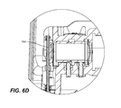
- FIG. 6D is a section of area F of FIG. 6C .
- FIGS. 7-11 are different views of the optics module assembly and components of reader 100 .
- Embodiments of the present invention therefore provide for hands-free operation.
- the scan will automatically take place.
- the user does not need to hold the passport or ID in place, or press any buttons to commence the scan.
- document insertion occurs along insertion path 130 ( FIG. 4 ) by passing a document across an upper surface or shelf 116 of the reader to a glass document scanning area, sometimes referred to as a platen 118 .
- the document insertion process is completed when the document comes to rest against a back-stop and side-stop which provide a consistent placement and alignment guide for the document.
- Prior designs for holding a document implement hard mechanical bodies to ensure a document is coerced flat to the imaging surface. These structures are observed to interfere with an operator's hands or require manipulations by the user. During the reading process, document placement is critical and must not be disrupted during the scanning process. Thus, a user must be able to insert a document and remove his/her hand without relocating or dislodging the document.
- the document should be held substantially flat against the surface 118 as failure to do so will result in poorly focused imagery and yield performance failures.
- the surface 118 also represents a reference plane for an RFID antenna/transmitter relationship between the reader and document (smartchip), placement in near proximity to the antenna is required to ensure successful data transfer.
- reader 100 does not impose discomfort or resistance to their exertions, as will be described below. Some examples of the document characteristics accommodated by reader 100 are described below.
- the hands-free design of reader 100 also accounts for varying body types of users. These traits include: hand thickness, hand length, or height (angle of insertion). It is also common for some users to wear jewelry, such as large rings.
- the nominal distance between the top of the platen and the lower surface of a light shield 112 is approximately one inch but may vary from about 0.8 to 1.2 inches in the central portion of the platen, which should accommodate the vast majority of commonly worn jewelry, while still sufficiently shielding from ambient light.
- the hands-free design does not impinge on the operator's ability to wear jewelry. The design allows the operator to complete the document reading processing using a single hand.
- the document reader 100 is an image capture device using, in a preferred embodiment, at least one light source during the reading process.
- at least one light source may employ multiply light sources of the same of varying type (e.g. infrared or invisible light).
- multiply light sources of the same e.g. infrared or invisible light.
- shield 112 that blocks such external light.
- the preferred embodiment of document reader 100 shown in the figures employs the use of brushes 110 (or other soft membrane substrates such as elastomers) in order to coerce a document flat to the document surface or platen 118 .
- brushes 110 or other soft membrane substrates such as elastomers
- three brushes 110 A, 110 B, and 110 C are incorporated into an upper housing of fixed document positioning device 150 , which serves a dual purpose as an ambient light shield.
- Document positioning device 150 is fixed, which is to say it does not need to be moved by a user to hold a document into place, as, for example is necessary in flatbed scanners where a hinged cover must be rotated into place to hold a document flat against the scanner platen so that it can be properly imaged.
- Central brush 110 B is considerably shorter than side brushes 110 A and 110 C.
- Central brush 110 B is approximately one inch or less, and is preferably 0.7 inches in length whereas side brushes 110 A and 110 C are approximately two to three inches in length, and preferably about 2.8 inches in length.
- Central brush 110 A is as at the apex of cutout 112 C ( FIG. 4 ) of light shield 112 .
- Cutout 112 C and in general the shape of light shield 112 , allows a user to enter his/her hand into the fixed positioning device 150 in an area over the platen 118 in order to slide the material to be read into the proper position.
- the comparatively shorter length of central brush 110 B also provides less resistance to insertion at the central portion of document/platen.
- the length, orientation, and height of the brushes have been optimized to provide the following:
- Side brushes 110 A and 110 C are oriented off-axis (slanted) in order to minimize pinching force that occurs as a bristle sweeps through its at-rest (straight) position.
- Brush height of about 0.74-0.78 (preferably 0.75) inches in the preferred embodiment provides sufficient stroke length to accommodate up to four multi-bound passports. Note that this may vary depending on the type of passport and may be less in certain embodiments designed to accommodate a lesser number of passports.
- the brush height is the same for both the center and side angled brushes.
- Central brush 110 B is oriented at an angle substantially perpendicular to the surface of platen 118
- side brushes 110 A and 110 C are preferably oriented at an angle other than perpendicular to the platen and the document page of interest.
- the side brushes 110 A and 110 C are oriented at about 24 to 26 degrees from vertical.
- the cant of the brushes may be oriented towards or away form the outside edges of the document and platen.
- the side brushes can therefore deflect to a greater degree than if the bristles were oriented perpendicularly to the platen.
- the brushes are spaced approximately 3.8 inches apart from each other. This provides: a) Displacement area for engaged brush; b) Unimpeded location for hand/finger insertion; and c) Document retention along the left and right document edges to combat document curl, and center brush location to combat document bowing.
- reader 100 incorporates a clear window as part of the platen 118 , which is preferably made of glass but may be made of any transparent material.
- a document is slid onto the window in a sweeping motion along document insertion path 130 .
- the body of reader 100 is polymeric and the junction or seam between the body and the window is a potential location where documents may get snagged as they are slid onto or off of the window.
- an upper shelf 116 of the body of reader 100 incorporates a document insertion deflection structure 140 .
- Deflection structure 140 is preferably an arcuate or rounded structure with a gradual transition from the leading and trailing edges to the highest portion.
- the upper shelf features a beveled or rounded edge at the seam so that when identification cards (that fit entirely on the platen) are removed they do not snag on the seam.
- Reader 100 is operable to read electronic or “smart” passports in accordance with ISO14443 and comprises an RFID antenna/transmitter, as described in the ISO standard, hereby incorporated by reference in the entirety.
- FIG. 6A is a section of reader 100
- FIG. 6B is a section of area E shown in FIG. 6A
- Infrared transmitter 162 is used to illuminate material to be read, which is reflected from the material and captured by image capture sensor 164
- FIG. 6C is another section of reader 100
- FIG. 6D is a section of area F of FIG. 6C .
- Initial document detection sequences take advantage of the flexibility and high degree of information content by sampling data from the digital image capture sensor 164 .
- image capture sensor 164 for identifying the presence of a document not only initiates the capture process but information gathered with regard to document shape, position and orientation, is also passed to the processor to optimize system performance.
- Imaging based documentation schemas One disadvantage with imaging based documentation schemas is their susceptibility to false events induced by extraneous image related events, such as light shadows induced by a passerby or environmental lighting changes. To distinguish between whether a document is present and these extraneous events reader 100 uses a unique process of lighting variation detection followed by image based analysis for document structure characteristics.
- Lighting variation detection is accomplished by monitoring a parameter within the imaging device which surveys the average brightness as witnessed by the sensor.
- reader 100 preferably employs the use of infrared lighting. Use of infrared lighting additionally limits the nuisance to the operator in having white light emitting towards them while the system is waiting for document scanning.
- Document structure analysis is performed whereby normal document traits, such as orthogonal edges, bright field content, and orthogonally oriented content composition are recognized.
- infrared receiver 160 which in a preferred embodiment comprises one or more photodiodes.
- Receiver 160 is arranged such that exposure to the infrared lighting will be detected by the photodiode, and in one preferred embodiment saturates the photodiode junction.
- the photodiode is modulated to supply a binary signal to a detection algorithm via microprocessor control. As an object is passed by the photodiode, the transmission of infrared energy is obstructed thereby prohibiting reception and/or saturation of the photodiode.
- reader 100 employs a unique arrangement by creating an assembly that orients the diode in a manner to favor position specific document detection in a light emission field that exposes a broad document surface. This unique orientation mechanism allows simultaneous usage of infrared lighting to illuminate to imaging target and for document detection purposes.
- the photodiode is aligned such that it is biased by the emitter illumination source in a position that intersects the platen about 0.75 to 1.0 inches, (preferably 0.84 inches) from the rear document stop and about 0.75 to 1.0 inches (preferably 0.82 inches) in height above the platen at an angle of about 30-40 (preferably 35) degrees.
- Reader 100 employs the use of injection molded bodies that incorporate integrated alignment mechanisms. It also includes part marriage component design that engages body to body reference as to not require manufacturing assembly attentiveness. Spring loaded floating component techniques ensure the direct mating of the camera sensor to ensure orthogonal placement with regard to optical lens alignment. Mounting consideration of the optical lens enables a post assembly focus adjustment unlike the prior art. Further, the camera alignment for lateral position and skew is facilitated by the floating spring design in conjunction with camera circuit board features to also allow unique post assembly alignment during the manufacturing process. Optics module assembly 200 is illustrated in FIGS. 7-11 .
- any optical lens it is required to position the lens between the object of attention and the image that is formed at a target location. In the present case, this position is between the document and the digital camera sensor. If the lens is not positioned for optimal optical conditions, the system will not achieve its intended image resolution prescription.
- reader lens 206 incorporates a simple barrel design. Grooves or slots are incorporated in the barrel design for the mounting of a C-style compression ring 208 .
- This ring is used in conjunction with an orthogonally arranged wedge driving screw (focus screw 210 ( FIG. 9 )) to transfer directional force of the screw in a directional force 204 along the lens axis.
- focus screw 210 FIG. 9
- the lens When mounted in its housing, the lens is engaged with a curved spring disk 202 which acts to impose an opposing force along the lens axis to the prior mentioned compression ring arrangement.
- the focus screw is adjusted, the lens position is altered in a direction orthogonal to the focus screw on axis with the camera sensor. This motion and orientation defines the optical axis and provides a means for positioning the lens for optimal focus.
- lens design compression ring, focus screw, lens body mount, and curved spring disk 202 utilizes inexpensive commonly available components to achieve extremely precise lens focus action.
- lens mount devices such as threaded sleeves or gear driven mechanisms to achieve lens positioning, which have significantly higher fabrication costs, and are therefore less desirable.
- the focus screw 210 is further equipped with a dual nut retention feature 210 B.
- a single nut is required to provide a thread for the screw action whereas the second nut provides extended screw alignment to ensure precise positioning with regard to the compression ring where the screw is housed in the injection molded housing. This technique is a detail that ensures success in achieving precision using economical components.
- the focus screw 210 is paired with an accompanying retention screw 212 to hold the lens in place in its final optical position.
- Embodiments of reader 100 incorporate injection molded body design that employ orthogonal reference planes for the lens and camera sensor. The challenge in achieving this relationship balances the limited availability of material in an interlocking design where structural support of adjoining members accommodates weaker substructures.
- the principle feature that establishes the orthogonal relationship of the lens and sensor are the protrusions 222 ( FIG. 10 ) that extend downward from the upper optical lens mount body ( FIG. 10 ).
- the protrusions 222 By establishing the upper body as the base of optic alignment, no alignment attentiveness is required during manufacture assembly between the upper and lower assembly cavities ( FIG. 10 ).
- Protrusions 222 are inserted between the limited gap allowed between the lens and camera sensor device in order to comply with optical design requirements; optical design requires tight placement between the lens and the digital image sensor device.
- injection molded components require a tapering in their structure, establishing a solution using thin wall design is limited by the tapering of these structural walls. Thin walls are extremely susceptible to deformation during the molding process where unformed molting plastic is cured to define a rigid body part.
- the thin walled protrusions 222 are engaged in the lower assembly cavity.
- a method was devised to use the lower cavity to reform the protrusions into proper position by the marriage of the upper and lower cavities. This engagement establishes an alignment of the two bodies while simultaneously supporting the thinner weak protrusion construction by the larger thick walled lower structure.
- the lens barrel design includes a chamfer 224 in order to provide adequate material to support the protrusion engagement interface 226
- Reader 100 achieves this with an arrangement of spring loaded retention screws (described below) to both hold the camera in its final position while simultaneously allowing positional adjustment.
- Positioning the sensor along the lens sensor plane occurs through an arrangement of three adjustment screws: two screws 242 for vertical and skew adjustment, one screw 236 for horizontal adjustment.
- the springs use a similar arrangement using precision compression springs to induce opposing forces to the adjustment screw. This force not only ensures engagement with the screw but imposes sufficient force to hold the camera in its final location throughout the life of the product.
- This arrangement of readily available inexpensive components continues to support the economic advantages in this assembly process while yielding specification tolerance control not normally achieved with low cost injection mold design.
- the action of the vertical and skew adjustment screws 242 is achieved by an arrangement of two screws along the bottom of the camera sensor circuit board 246 .
- the opposing force for these adjusting screws is applied by precision compression springs 232 on the adjacent side of the circuit board.
- Skew correction is achieved by adjusting the screws 242 in opposing directions.
- the upward force on one screw in conjunction with the downward force on the second screw induces a rotational orientation change.
- Vertical position correction is achieved by adjusting these screws in the same direction.
- the horizontal position action is created by an arrangement of an adjustment screw 236 in a similarly arranged configuration that captures a precision compression spring which imposes force on the capturing nut.
- the nut 234 is arranged whereby adjustment of the screw induces an upward/downward motion on the nut.
- the nut due to its arrangement with the camera circuit board, which employs a wedge shape design mating with the nut, induces a horizontal translation of the circuit board by the vertical translation of the nut.
- An opposing spring 244 is designed to ensure suitable force to oppose the direction of the nut/wedge translation.
Abstract
Description
-
- 1) Passport size—World-wide production of passports yields many different styles and types of documents. Type variations alter the manner of document insertion.
Reader 100 accommodates such variations which include: rigid plastic card type document stock, flimsy thin-paper style document stock, and size variants from 4.9-6.0 inch document widths and approximately 4 inches in height. The maximum opening width is 6.0 inches and the maximum opening height is 0.61 inches. - 2) ID size—Identity documents come is many shapes and sizes. The most common ID (such as a driver's license in the U.S.) is a rigid card stock with 3⅜ inches width and 2⅛ inches in height. Such an ID can also be read by the
reader 100. - 3) Passport construction—Some passports possess binding designs whereby there insistence on remaining closed acts against the user's exertions to insert the document. The passport's natural tendency is to not remain flat in the proper reading position. A successful design requires holding a document in place while a user is no longer engaged with the document
- 4) Worn documents—The characteristics and rigidity of a worn document can vary depending on document construction material. Of particular note is the soft bound passport style that tends to curl or warp across the document surface. Successful hands free design must make concessions to coerce these deformations into proper reading position.
- 5) Multi-bound documents—It is not uncommon for a certain percentage of travelers to maintain and
use 2 or 3 outdated passports. This behavior is necessary for travelers where expired passports contain non-expired visas. There is a tendency among such travelers to either staple or use rubber bands to bind several documents together. Asking them to separate the documents during the border clearance stage would introduce delays in the work flow model. Thus, accommodating booklet thicknesses 2-3 times the normal passport thickness is desired and is a feature of the embodiments of the present invention.
- 1) Passport size—World-wide production of passports yields many different styles and types of documents. Type variations alter the manner of document insertion.
Claims (7)
Priority Applications (1)
| Application Number | Priority Date | Filing Date | Title |
|---|---|---|---|
| US13/866,817 US9007664B2 (en) | 2007-05-10 | 2013-04-19 | Identification reader |
Applications Claiming Priority (3)
| Application Number | Priority Date | Filing Date | Title |
|---|---|---|---|
| US92882507P | 2007-05-10 | 2007-05-10 | |
| US12/118,009 US8493630B2 (en) | 2007-05-10 | 2008-05-09 | Identification reader |
| US13/866,817 US9007664B2 (en) | 2007-05-10 | 2013-04-19 | Identification reader |
Related Parent Applications (1)
| Application Number | Title | Priority Date | Filing Date |
|---|---|---|---|
| US12/118,009 Division US8493630B2 (en) | 2007-05-10 | 2008-05-09 | Identification reader |
Publications (2)
| Publication Number | Publication Date |
|---|---|
| US20130235435A1 US20130235435A1 (en) | 2013-09-12 |
| US9007664B2 true US9007664B2 (en) | 2015-04-14 |
Family
ID=40095610
Family Applications (2)
| Application Number | Title | Priority Date | Filing Date |
|---|---|---|---|
| US12/118,009 Active 2032-04-24 US8493630B2 (en) | 2007-05-10 | 2008-05-09 | Identification reader |
| US13/866,817 Active US9007664B2 (en) | 2007-05-10 | 2013-04-19 | Identification reader |
Family Applications Before (1)
| Application Number | Title | Priority Date | Filing Date |
|---|---|---|---|
| US12/118,009 Active 2032-04-24 US8493630B2 (en) | 2007-05-10 | 2008-05-09 | Identification reader |
Country Status (1)
| Country | Link |
|---|---|
| US (2) | US8493630B2 (en) |
Families Citing this family (53)
| Publication number | Priority date | Publication date | Assignee | Title |
|---|---|---|---|---|
| GB0522968D0 (en) | 2005-11-11 | 2005-12-21 | Popovich Milan M | Holographic illumination device |
| GB0718706D0 (en) | 2007-09-25 | 2007-11-07 | Creative Physics Ltd | Method and apparatus for reducing laser speckle |
| US11557163B2 (en) | 2006-08-16 | 2023-01-17 | Isonas, Inc. | System and method for integrating and adapting security control systems |
| US9153083B2 (en) | 2010-07-09 | 2015-10-06 | Isonas, Inc. | System and method for integrating and adapting security control systems |
| US9589400B2 (en) | 2006-08-16 | 2017-03-07 | Isonas, Inc. | Security control and access system |
| US7775429B2 (en) | 2006-08-16 | 2010-08-17 | Isonas Security Systems | Method and system for controlling access to an enclosed area |
| JP5106298B2 (en) * | 2008-07-30 | 2012-12-26 | キヤノン株式会社 | Image reading device |
| JP4471401B1 (en) * | 2008-12-05 | 2010-06-02 | パナソニック株式会社 | Form reader and form detection method |
| US9335604B2 (en) | 2013-12-11 | 2016-05-10 | Milan Momcilo Popovich | Holographic waveguide display |
| US11726332B2 (en) | 2009-04-27 | 2023-08-15 | Digilens Inc. | Diffractive projection apparatus |
| US9341846B2 (en) | 2012-04-25 | 2016-05-17 | Rockwell Collins Inc. | Holographic wide angle display |
| US11204540B2 (en) | 2009-10-09 | 2021-12-21 | Digilens Inc. | Diffractive waveguide providing a retinal image |
| US9274349B2 (en) | 2011-04-07 | 2016-03-01 | Digilens Inc. | Laser despeckler based on angular diversity |
| US8827162B2 (en) * | 2011-04-29 | 2014-09-09 | Ncr Corporation | Travel kiosk |
| WO2016020630A2 (en) | 2014-08-08 | 2016-02-11 | Milan Momcilo Popovich | Waveguide laser illuminator incorporating a despeckler |
| US10670876B2 (en) | 2011-08-24 | 2020-06-02 | Digilens Inc. | Waveguide laser illuminator incorporating a despeckler |
| EP2748670B1 (en) | 2011-08-24 | 2015-11-18 | Rockwell Collins, Inc. | Wearable data display |
| US8794515B2 (en) | 2011-11-07 | 2014-08-05 | Jeremy Krell | Alcohol delivery management system |
| US20150010265A1 (en) | 2012-01-06 | 2015-01-08 | Milan, Momcilo POPOVICH | Contact image sensor using switchable bragg gratings |
| US9456744B2 (en) | 2012-05-11 | 2016-10-04 | Digilens, Inc. | Apparatus for eye tracking |
| US9933684B2 (en) * | 2012-11-16 | 2018-04-03 | Rockwell Collins, Inc. | Transparent waveguide display providing upper and lower fields of view having a specific light output aperture configuration |
| WO2014188149A1 (en) | 2013-05-20 | 2014-11-27 | Milan Momcilo Popovich | Holographic waveguide eye tracker |
| US9727772B2 (en) | 2013-07-31 | 2017-08-08 | Digilens, Inc. | Method and apparatus for contact image sensing |
| US10359736B2 (en) | 2014-08-08 | 2019-07-23 | Digilens Inc. | Method for holographic mastering and replication |
| WO2016042283A1 (en) | 2014-09-19 | 2016-03-24 | Milan Momcilo Popovich | Method and apparatus for generating input images for holographic waveguide displays |
| US10423222B2 (en) | 2014-09-26 | 2019-09-24 | Digilens Inc. | Holographic waveguide optical tracker |
| CN107873086B (en) | 2015-01-12 | 2020-03-20 | 迪吉伦斯公司 | Environmentally isolated waveguide display |
| EP3245551B1 (en) | 2015-01-12 | 2019-09-18 | DigiLens Inc. | Waveguide light field displays |
| WO2016116733A1 (en) | 2015-01-20 | 2016-07-28 | Milan Momcilo Popovich | Holographic waveguide lidar |
| US9632226B2 (en) | 2015-02-12 | 2017-04-25 | Digilens Inc. | Waveguide grating device |
| WO2016146963A1 (en) | 2015-03-16 | 2016-09-22 | Popovich, Milan, Momcilo | Waveguide device incorporating a light pipe |
| WO2016156776A1 (en) | 2015-03-31 | 2016-10-06 | Milan Momcilo Popovich | Method and apparatus for contact image sensing |
| WO2017060665A1 (en) | 2015-10-05 | 2017-04-13 | Milan Momcilo Popovich | Waveguide display |
| EP3398007A1 (en) | 2016-02-04 | 2018-11-07 | DigiLens, Inc. | Holographic waveguide optical tracker |
| JP6895451B2 (en) | 2016-03-24 | 2021-06-30 | ディジレンズ インコーポレイテッド | Methods and Devices for Providing Polarized Selective Holography Waveguide Devices |
| JP6734933B2 (en) | 2016-04-11 | 2020-08-05 | ディジレンズ インコーポレイテッド | Holographic Waveguide Device for Structured Light Projection |
| WO2018102834A2 (en) | 2016-12-02 | 2018-06-07 | Digilens, Inc. | Waveguide device with uniform output illumination |
| US10545346B2 (en) | 2017-01-05 | 2020-01-28 | Digilens Inc. | Wearable heads up displays |
| EP3698214A4 (en) | 2017-10-16 | 2021-10-27 | Digilens Inc. | Systems and methods for multiplying the image resolution of a pixelated display |
| US10914950B2 (en) | 2018-01-08 | 2021-02-09 | Digilens Inc. | Waveguide architectures and related methods of manufacturing |
| KR20200108030A (en) | 2018-01-08 | 2020-09-16 | 디지렌즈 인코포레이티드. | System and method for high throughput recording of holographic gratings in waveguide cells |
| US10690851B2 (en) | 2018-03-16 | 2020-06-23 | Digilens Inc. | Holographic waveguides incorporating birefringence control and methods for their fabrication |
| CN208337689U (en) * | 2018-04-10 | 2019-01-04 | 深圳市商汤科技有限公司 | A kind of image capture device |
| EP3811277B1 (en) | 2018-06-21 | 2022-04-13 | Custom S.p.A. | Apparatus for inspecting documents |
| US11402801B2 (en) | 2018-07-25 | 2022-08-02 | Digilens Inc. | Systems and methods for fabricating a multilayer optical structure |
| EP3832997A4 (en) * | 2018-07-27 | 2022-03-02 | Pfu Limited | Image reading device |
| CN109446867B (en) * | 2018-12-26 | 2024-02-06 | 天地融科技股份有限公司 | Passport reader |
| JP2022520472A (en) | 2019-02-15 | 2022-03-30 | ディジレンズ インコーポレイテッド | Methods and equipment for providing holographic waveguide displays using integrated grids |
| KR20210134763A (en) | 2019-03-12 | 2021-11-10 | 디지렌즈 인코포레이티드. | Holographic waveguide backlights and related manufacturing methods |
| KR20220016990A (en) | 2019-06-07 | 2022-02-10 | 디지렌즈 인코포레이티드. | Waveguides incorporating transmission and reflection gratings and related manufacturing methods |
| JP2022543571A (en) | 2019-07-29 | 2022-10-13 | ディジレンズ インコーポレイテッド | Method and Apparatus for Multiplying Image Resolution and Field of View for Pixelated Displays |
| EP4022370A4 (en) | 2019-08-29 | 2023-08-30 | Digilens Inc. | Evacuating bragg gratings and methods of manufacturing |
| US11182572B2 (en) * | 2019-12-20 | 2021-11-23 | Zebra Technologies Corporation | System and method of selective auxiliary data capture |
Citations (12)
| Publication number | Priority date | Publication date | Assignee | Title |
|---|---|---|---|---|
| US3661452A (en) | 1968-05-24 | 1972-05-09 | Xerox Corp | Xerographic reproduction machine |
| US4403851A (en) | 1979-03-09 | 1983-09-13 | Ricoh Company, Ltd. | Electrostatic copying machine comprising improved arrangement of operating units |
| US5173953A (en) * | 1984-09-07 | 1992-12-22 | Canon Kabushiki Kaisha | Image file system capable of inserting images into a sequence of stored images |
| US5237431A (en) * | 1990-06-19 | 1993-08-17 | Fuji Xerox Co., Ltd. | Image reading apparatus for producing high quality images based on tone correction |
| US5804805A (en) * | 1986-08-08 | 1998-09-08 | Norand Technology Corporation | Hand-held optical indicia reader having a controlled oscillating system for optimal indicia reading |
| US5915691A (en) | 1994-10-17 | 1999-06-29 | Sharp Kabushiki Kaisha | Document feeder and cover for an image forming apparatus |
| US5969321A (en) * | 1986-08-08 | 1999-10-19 | Norand Corporation | Hand-held optically readable information set reader with operation over a range of distances |
| US6678977B1 (en) | 2003-01-21 | 2004-01-20 | Alan Sherman | Document holder |
| US20050241092A1 (en) | 2004-03-26 | 2005-11-03 | Sharp Kabushiki Kaisha | Rotatable brush manufacturing method, rotatable brush, charging apparatus, image forming apparatus, and cleaning apparatus for a rotatable brush |
| US20070181664A1 (en) | 2006-01-31 | 2007-08-09 | Cssn Inc | System and method for creating a badge for a conference or exhibition visitor from a scanned id document |
| US20080037076A1 (en) | 2006-03-24 | 2008-02-14 | Takashi Ohama | Document reading apparatus |
| US7495809B2 (en) * | 2002-12-13 | 2009-02-24 | Avision Inc. | Scanning device capable of quickly starting scanning |
-
2008
- 2008-05-09 US US12/118,009 patent/US8493630B2/en active Active
-
2013
- 2013-04-19 US US13/866,817 patent/US9007664B2/en active Active
Patent Citations (12)
| Publication number | Priority date | Publication date | Assignee | Title |
|---|---|---|---|---|
| US3661452A (en) | 1968-05-24 | 1972-05-09 | Xerox Corp | Xerographic reproduction machine |
| US4403851A (en) | 1979-03-09 | 1983-09-13 | Ricoh Company, Ltd. | Electrostatic copying machine comprising improved arrangement of operating units |
| US5173953A (en) * | 1984-09-07 | 1992-12-22 | Canon Kabushiki Kaisha | Image file system capable of inserting images into a sequence of stored images |
| US5804805A (en) * | 1986-08-08 | 1998-09-08 | Norand Technology Corporation | Hand-held optical indicia reader having a controlled oscillating system for optimal indicia reading |
| US5969321A (en) * | 1986-08-08 | 1999-10-19 | Norand Corporation | Hand-held optically readable information set reader with operation over a range of distances |
| US5237431A (en) * | 1990-06-19 | 1993-08-17 | Fuji Xerox Co., Ltd. | Image reading apparatus for producing high quality images based on tone correction |
| US5915691A (en) | 1994-10-17 | 1999-06-29 | Sharp Kabushiki Kaisha | Document feeder and cover for an image forming apparatus |
| US7495809B2 (en) * | 2002-12-13 | 2009-02-24 | Avision Inc. | Scanning device capable of quickly starting scanning |
| US6678977B1 (en) | 2003-01-21 | 2004-01-20 | Alan Sherman | Document holder |
| US20050241092A1 (en) | 2004-03-26 | 2005-11-03 | Sharp Kabushiki Kaisha | Rotatable brush manufacturing method, rotatable brush, charging apparatus, image forming apparatus, and cleaning apparatus for a rotatable brush |
| US20070181664A1 (en) | 2006-01-31 | 2007-08-09 | Cssn Inc | System and method for creating a badge for a conference or exhibition visitor from a scanned id document |
| US20080037076A1 (en) | 2006-03-24 | 2008-02-14 | Takashi Ohama | Document reading apparatus |
Non-Patent Citations (2)
| Title |
|---|
| U.S. Notice of Allowance dated Mar. 21, 2013 issued in U.S. Appl. No. 12/118,009. |
| U.S. Office Action dated Sep. 25, 2012 issued in U.S. Appl. No. 12/118,009. |
Also Published As
| Publication number | Publication date |
|---|---|
| US20080304111A1 (en) | 2008-12-11 |
| US20130235435A1 (en) | 2013-09-12 |
| US8493630B2 (en) | 2013-07-23 |
Similar Documents
| Publication | Publication Date | Title |
|---|---|---|
| US9007664B2 (en) | Identification reader | |
| EP2945095B1 (en) | Indicia-reader housing with an integrated optical structure | |
| US5786586A (en) | Hand-held optical reader having a detachable lens-guide assembly | |
| US10474859B2 (en) | Barcode reader and docking station for charging the barcode reader | |
| TWI504230B (en) | Image reading device | |
| EP2912600B1 (en) | Compact imaging module with adjustable aiming pattern and arrangement for and method of spatially adjusting the aiming pattern | |
| US8167210B2 (en) | System for increasing imaging quality | |
| US20190166278A1 (en) | Information reading device | |
| US9830002B2 (en) | Barcode reader and docking station for charging the barcode reader | |
| CA2193041A1 (en) | Mouse adapted to scan biometric data | |
| EP2996064B1 (en) | Stationary-type information-code reading apparatus | |
| GB2400714A (en) | Combined optical fingerprint recogniser and navigation control | |
| WO2010138013A4 (en) | Handheld portable device for verification of travel and personal documents, reading of biometric data and identification of persons holding these documents | |
| CN101030250A (en) | Terminal and processing method thereof | |
| JP2003506798A (en) | Method and apparatus for reducing trapezoidal distortion and sharpening images in optical imaging systems | |
| US10321027B2 (en) | Imaging apparatus | |
| US20090059616A1 (en) | Illumination light assembly with self-retaining lightpipe for minimizing specular reflection in electro-optical reader | |
| US20150371070A1 (en) | Efficient optical illumination system and method for an imaging reader | |
| US11003882B2 (en) | Apparatus and method for reducing the effect of aim light aberrations in a barcode reader | |
| US9876372B2 (en) | Barcode reader and docking station for charging the barcode reader | |
| US20220067318A1 (en) | Card reader | |
| US20040028262A1 (en) | Optical system of fingerprint image capture apparatus | |
| KR200352669Y1 (en) | Identification card counterfeit discernment device | |
| US20140152791A1 (en) | Mobile Device Biometric Sensor Apparatus | |
| US7050158B2 (en) | Compact image pickup module |
Legal Events
| Date | Code | Title | Description |
|---|---|---|---|
| AS | Assignment |
Owner name: L-1 IDENTITY SOLUTIONS, INC., CONNECTICUT Free format text: ASSIGNMENT OF ASSIGNORS INTEREST;ASSIGNORS:QUEENAN, JAMES R.;SANROMA, JOHN P.;LAZZOUNI, MOHAMED;REEL/FRAME:032117/0497 Effective date: 20080509 |
|
| AS | Assignment |
Owner name: MORPHOTRUST USA, INC., MASSACHUSETTS Free format text: MERGER;ASSIGNOR:L-1 IDENTITY SOLUTIONS, INC.;REEL/FRAME:033552/0421 Effective date: 20121228 |
|
| AS | Assignment |
Owner name: MORPHOTRUST USA, LLC, MASSACHUSETTS Free format text: CHANGE OF NAME;ASSIGNOR:MORPHOTRUST USA, INC.;REEL/FRAME:033809/0742 Effective date: 20131220 |
|
| STCF | Information on status: patent grant |
Free format text: PATENTED CASE |
|
| FEPP | Fee payment procedure |
Free format text: MAINTENANCE FEE REMINDER MAILED (ORIGINAL EVENT CODE: REM.); ENTITY STATUS OF PATENT OWNER: LARGE ENTITY |
|
| FEPP | Fee payment procedure |
Free format text: SURCHARGE FOR LATE PAYMENT, LARGE ENTITY (ORIGINAL EVENT CODE: M1554); ENTITY STATUS OF PATENT OWNER: LARGE ENTITY |
|
| MAFP | Maintenance fee payment |
Free format text: PAYMENT OF MAINTENANCE FEE, 4TH YEAR, LARGE ENTITY (ORIGINAL EVENT CODE: M1551); ENTITY STATUS OF PATENT OWNER: LARGE ENTITY Year of fee payment: 4 |
|
| MAFP | Maintenance fee payment |
Free format text: PAYMENT OF MAINTENANCE FEE, 8TH YEAR, LARGE ENTITY (ORIGINAL EVENT CODE: M1552); ENTITY STATUS OF PATENT OWNER: LARGE ENTITY Year of fee payment: 8 |
|
| AS | Assignment |
Owner name: IDEMIA IDENTITY & SECURITY USA LLC, VIRGINIA Free format text: CHANGE OF NAME;ASSIGNOR:MORPHOTRUST USA LLC;REEL/FRAME:066928/0134 Effective date: 20171228 |