FIELD OF THE INVENTION
The present invention relates to a tape dispenser, and more particularly, to a tape dispenser with a simple structure and lower manufacturing cost.
BACKGROUND OF THE INVENTION
A conventional tape dispenser is disclosed in U.S. Pat. No. 6,311,923 and Taiwan Publication No. 439788 shown and generally includes a base, a frame and multiple suction members wherein the base has a recess for receiving a shaft therein so that the tape is mounted to the shaft. A blade is connected to the base. The base is a hollow base and a reception space is defined therein which opens to the top of the base so as to accommodate stationery accessories. A first connection portion is formed on the top of the base and has holes defined therethrough. The frame has a second connection portion which is connected to the first connection portion of the base. Each suction member has an engaging portion on the top thereof so as to be engaged with the holes in the base to position the suction members to the base to suck the frame. The frame is a hollow part which may be moved when the user pulls the tape. In order to improve the problem, weight such as sands or concrete is filled in the frame. The base, the frame and the shaft are made by plastic so that at least three sets of molds are required. The plastic shrinks during the molding processes, so that the there are tolerances between the connection faces between the parts and this can causes defectives to the products, especially for the parts with curved connection faces. The frame has two paths for accommodating the shaft and the paths are designed not to be straight to prevent the shaft from slip away, so that the molds have higher cost.
The present invention intends to provide a tape dispenser which has simple structure which is easily manufactured at lower cost.
SUMMARY OF THE INVENTION
The present invention relates to a tape dispenser and comprises a hollow body and a blade unit. The body has a frame, a blade seat and an opening. A reception portion is formed between the body and the frame so as to accommodate the tape. The opening communicates with inside of the body and the blade unit is located in the blade seat. The blade unit has a blade for cutting the tape.
The present invention will become more obvious from the following description when taken in connection with the accompanying drawings which show, for purposes of illustration only, a preferred embodiment in accordance with the present invention.
BRIEF DESCRIPTION OF THE DRAWINGS
FIG. 1 is an exploded view to show the tape dispenser of the present invention;
FIG. 2 is a top view of the tape dispenser of the present invention;
FIG. 3 is a cross sectional view, taken along line A-A in FIG. 2;
FIG. 4 is an exploded view to show the blade unit of the tape dispenser of the present invention;
FIG. 5 is a perspective view to show the blade unit of the tape dispenser of the present invention;
FIG. 6 is a perspective view to show the tape dispenser of the present invention;
FIG. 7 is a top view of the tape dispenser of the present invention;
FIG. 8 is a cross sectional view, taken along line B-B in FIG. 7;
FIG. 9 is a cross sectional view, taken along line C-C in FIG. 7;
FIG. 10 is a perspective view to show the second embodiment of the tape dispenser of the present invention;
FIG. 11 is a side view to show the blade of the second embodiment of the tape dispenser of the present invention;
FIG. 12 is an exploded view to show the third embodiment of the tape dispenser of the present invention;
FIG. 13 is a perspective view to show the fourth embodiment of the tape dispenser of the present invention;
FIG. 14 is an exploded view to show the fifth embodiment of the tape dispenser of the present invention;
FIG. 15 is a side view to show the blade of the fifth embodiment of the tape dispenser of the present invention;
FIG. 16 is a perspective view to show the sixth embodiment of the tape dispenser of the present invention;
FIG. 17 is a side view to show the blade of the sixth embodiment of the tape dispenser of the present invention;
FIG. 18 is a perspective view to show the seventh embodiment of the tape dispenser of the present invention;
FIG. 19 is an exploded view to show the eighth embodiment of the tape dispenser of the present invention;
FIG. 20 is a perspective view to show the ninth embodiment of the tape dispenser of the present invention;
FIG. 21 is a perspective view to show the tenth embodiment of the tape dispenser of the present invention;
FIG. 22 is a perspective view to show the eleventh embodiment of the tape dispenser of the present invention;
FIG. 23 is a perspective view to show the twelfth embodiment of the tape dispenser of the present invention;
FIG. 24 is an exploded view to show the thirteenth embodiment of the tape dispenser of the present invention;
FIG. 25 is a perspective view to show the thirteenth embodiment of the tape dispenser of the present invention;
FIG. 26 is a perspective view to show the fourteenth embodiment of the tape dispenser of the present invention;
FIG. 27 is a top view of the fourteenth embodiment of the tape dispenser of the present invention;
FIG. 28 is a front view of the fourteenth embodiment of the tape dispenser of the present invention;
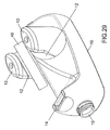
FIG. 29 is a perspective view to show the fifteenth embodiment of the tape dispenser of the present invention;
FIG. 30 is an exploded view to show the sixteenth embodiment of the tape dispenser of the present invention;
FIG. 31 is an exploded view to show the seventeenth embodiment of the tape dispenser of the present invention;
FIG. 32 is a perspective view to show the eighteenth embodiment of the tape dispenser of the present invention, and
FIG. 33 is a perspective view to show the nineteenth embodiment of the tape dispenser of the present invention.
DETAILED DESCRIPTION OF THE PREFERRED EMBODIMENT
Referring to FIG. 1, the tape dispenser of the present invention comprises a hollow body 10, a blade unit 20 and a seal member 30.
The body 10 is made by plastic ceramic or glass and has a frame 11 extending from one side thereof. A reception portion 12 is defined between the body 10 and the frame 11, and a tape 40 is put in the reception portion 12 which has two recesses 121 and two vertical portions 122. The two recesses 121 and the two vertical portions 122 are located alternatively to each other. The two vertical portions 122 are located at the front end and the rear end of the body 10. The frame 11 has a restriction portion 13 on the rear end thereof. A recessed blade seat 14 is defined in the front end of the body 10 and is located in opposite to the reception portion 12 along the axial direction of the body 10. The body 10 has an opening 15 which communicates with inside of the body 10, weight such as sands and concrete is located in the opening 15. The blade unit 20 is located in the blade seat 14 and has a blade 21 to cut the tape 40. A seal member 30 seals the opening 15 to prevent leakage of the weight from the opening 15.
As shown in FIGS. 2 and 3, each recess 121 has a curved face so that when the tap 40 is located in the reception portion 12, it is smoothly rotated and located corresponding to the blade unit 20. The restriction portion 13 is located at the rear end of the frame 11 and has a first protrusion 131 and a second protrusion 132 respectively extending from the top end and the bottom end of the restriction portion 13. The first protrusion 131 is higher than the second protrusion 132 so that the tape 40 is well positioned. A stop 16 is formed on the rear end of the body 10 to allow the tape dispenser to stand upright.
As shown in FIGS. 4 and 5, the blade unit 20 has a blade 21 and a blade carrier 22. The blade 21 has a flange 211 and is shaped as an inverted N. The blade carrier 22 has two connected plastic parts and each part has an edge 221 with a recessed area 222 defined therein. The two parts are connected to each other to clamp the blade 21. The flange 211 is engaged with the recessed areas 222, and the edge 221 restricts the flange 211 so that the blade 21 is connected to the blade carrier 22. The blade carrier 22 is engaged with the blade seat 14.
As shown in FIGS. 6 to 9, the blade carrier 22 is engaged with the blade seat 14, the seal member 30 seals the opening 15. The tape 40 is mounted to the reception portion 12 and located corresponding to the blade unit 20.
As shown in FIGS. 10 and 11, the restriction portion 13 faces upward, downward or rearward, and has only the first protrusion 131. The rear end of the contact end 16 has the handle 161 extending therefrom. The blade 21 is a U-shaped blade and has an elastic pressing portion 213 which is engaged with the blade seat 14.
As shown in FIG. 12, in one embodiment, the frame 11 is a single part and the body 10 has a first connection portion 17 to which the frame 11 is securely connected. The opening 15 has a threaded portion defined in the outside thereof and a cover is threadedly connected to the threaded portion.
In one embodiment, as shown in FIG. 13, the restriction portion 13 has multiple bosses.
As shown in FIGS. 14 and 15, in one embodiment, the frame 11 has at least recessed accessories stand 18 defined in the rear end thereof and at least one restriction member 50 is located in the accessories stand 18. The at least one restriction member 50 can be a pen, scissors, a box cutter and other stationery. The at least one restriction member 50 plays a role as the restriction portion 13. The accessory stand 18 accommodates the tape 40. The opening 15 is located at the bottom of the body 10 and the blade 21 is a U-shaped blade and has a pressing portion 212 which is engaged with the blade seat 14.
As shown in FIGS. 16 and 17, in one embodiment, the recess 121 is a V-shaped recess and the tape 40 is located at the middle portion of the reception portion 12. A width scale 133 is installed to the body 10 and located at the end face of the frame 11 to show width of the tape 40. The blade 21 is an L-shaped blade. The blade unit 20 has a pressing member 23 which is connected to the blade 21, and then connection is engaged with the blade seat 14.
As shown in FIG. 18, in one embodiment, the recesses 121 are stepped recesses so as to accommodate the tapes 40 of different widths and the tape 40 is located corresponding to the blade unit 20.
As shown in FIG. 19, in one embodiment, a collar 60 is mounted to the reception portion 12 and has a stop 61, the tape 40 is mounted to the collar 60 and restricted by the stop 61. The tape dispenser of the present invention can be used with the tapes of different inner diameters by the collar 60. The collar 60 is rotatable relative to the reception portion 12 and the tape 40 is co-rotated with the collar 60 when being pulled.
As shown in FIG. 20, in one embodiment, a bent portion 19 is located between the body 10 and the blade seat 14 so as to adjust length of the body 10 and the distance between the reception portion 12 and the blade seat 14.
As shown in FIG. 21, in one embodiment, a bottom of the body 10 is located at the bent portion 19 so as to adjust length of the body 10 as needed. When the tape dispenser drops on the floor, the bent portion 19 buffers the impact. The bent portion 19 also provides an expandable space for the sands in the body 10. Alternatively, the reception portion 12 of the body 10 may have a bent portion 19 so that the reception portion 12 is extendable.
As shown in FIG. 22, in one embodiment, the body 10 has an accessory stand 18 extending from one side thereof.
As shown in FIG. 23, in one embodiment, the blade seat 14 is a single part which is removably connected to the body 10.
As shown in FIGS. 24 and 25, in one embodiment, there are two reception portions 12 so as to accommodate the tapes 40 of different inner diameters.
As shown in FIGS. 26 and 27, in one embodiment, the body 10 has the frame 11 and the blade seat 14 on two sides thereof, the frame 11 accommodates the tape 40. The blade seat 14 has an inclined portion and the blade unit 20 or the blade 21 is engaged with the blade seat 14. The blade 21 has an inclined portion relative to the tape 40.
As shown in FIGS. 28 and 29, in one embodiment, there are two frames 11 located on two sides of the body 10 and extend inclinedly relative to the body 10.
As shown in FIG. 30, in one embodiment, the body 10 has multiple slots 191 and the frame 11 is a linear frame and is bent to the frame 80 as shown which has multiple first engaging portions 81, reception portions 82 and restriction portion 83. The first engaging portions 81 are engaged with the slots 191, and the reception portions 82 accommodate the tape 40 which is restricted by the restriction portions 83.
As shown in FIG. 31, in one embodiment, an elastic bushing 62 is located between the collar 60 and the reception portion 12, and the collar 60 is mounted to the reception portion 12 by the bushing 62.
As shown in FIG. 32, in one embodiment, the blade seat 14 has a first extension 141 and a second extension 142 so as to be engaged with the blade 21.
As shown in FIG. 33, in one embodiment, the body 10 has two blade seats 14 located at two ends thereof.
The body 10 is a hollow part and the frame 11 on one side of the body 10 is a single part so as to reduce the manufacturing cost. The body 10 has a thin crust which allows small tolerance when being molded, and patterns, logos, characters can be made on the surface of the body 10. The hollow body 10 has the opening 15 through which the sands, concrete or fluid can be easily filled in the body 10. The frame 11 is located on one side of the body 10 and the tape 40 is connected to the framell so that the replacement of the tape 40 is easy. The parting line of the body 10 is located on the vertical portion 122 so that the top mold and the bottom mold is connected at the vertical portion 122, so that the bottom of the body 10 is required to be smaller than the vertical portion 122, the body 10 is easily removed from the molds.
While we have shown and described the embodiment in accordance with the present invention, it should be clear to those skilled in the art that further embodiments may be made without departing from the scope of the present invention.