US9018854B2 - Lighting system with reduced physioneural compression and associate methods - Google Patents
Lighting system with reduced physioneural compression and associate methods Download PDFInfo
- Publication number
- US9018854B2 US9018854B2 US13/830,390 US201313830390A US9018854B2 US 9018854 B2 US9018854 B2 US 9018854B2 US 201313830390 A US201313830390 A US 201313830390A US 9018854 B2 US9018854 B2 US 9018854B2
- Authority
- US
- United States
- Prior art keywords
- light source
- light
- period
- controller
- emit
- Prior art date
- Legal status (The legal status is an assumption and is not a legal conclusion. Google has not performed a legal analysis and makes no representation as to the accuracy of the status listed.)
- Active, expires
Links
Images


Classifications
-
- H05B37/0281—
-
- A—HUMAN NECESSITIES
- A61—MEDICAL OR VETERINARY SCIENCE; HYGIENE
- A61M—DEVICES FOR INTRODUCING MEDIA INTO, OR ONTO, THE BODY; DEVICES FOR TRANSDUCING BODY MEDIA OR FOR TAKING MEDIA FROM THE BODY; DEVICES FOR PRODUCING OR ENDING SLEEP OR STUPOR
- A61M21/00—Other devices or methods to cause a change in the state of consciousness; Devices for producing or ending sleep by mechanical, optical, or acoustical means, e.g. for hypnosis
-
- A—HUMAN NECESSITIES
- A61—MEDICAL OR VETERINARY SCIENCE; HYGIENE
- A61N—ELECTROTHERAPY; MAGNETOTHERAPY; RADIATION THERAPY; ULTRASOUND THERAPY
- A61N5/00—Radiation therapy
- A61N5/06—Radiation therapy using light
- A61N5/0613—Apparatus adapted for a specific treatment
- A61N5/0618—Psychological treatment
-
- H05B33/0857—
-
- H—ELECTRICITY
- H05—ELECTRIC TECHNIQUES NOT OTHERWISE PROVIDED FOR
- H05B—ELECTRIC HEATING; ELECTRIC LIGHT SOURCES NOT OTHERWISE PROVIDED FOR; CIRCUIT ARRANGEMENTS FOR ELECTRIC LIGHT SOURCES, IN GENERAL
- H05B45/00—Circuit arrangements for operating light-emitting diodes [LED]
- H05B45/20—Controlling the colour of the light
-
- H—ELECTRICITY
- H05—ELECTRIC TECHNIQUES NOT OTHERWISE PROVIDED FOR
- H05B—ELECTRIC HEATING; ELECTRIC LIGHT SOURCES NOT OTHERWISE PROVIDED FOR; CIRCUIT ARRANGEMENTS FOR ELECTRIC LIGHT SOURCES, IN GENERAL
- H05B47/00—Circuit arrangements for operating light sources in general, i.e. where the type of light source is not relevant
- H05B47/10—Controlling the light source
- H05B47/16—Controlling the light source by timing means
-
- A—HUMAN NECESSITIES
- A61—MEDICAL OR VETERINARY SCIENCE; HYGIENE
- A61M—DEVICES FOR INTRODUCING MEDIA INTO, OR ONTO, THE BODY; DEVICES FOR TRANSDUCING BODY MEDIA OR FOR TAKING MEDIA FROM THE BODY; DEVICES FOR PRODUCING OR ENDING SLEEP OR STUPOR
- A61M21/00—Other devices or methods to cause a change in the state of consciousness; Devices for producing or ending sleep by mechanical, optical, or acoustical means, e.g. for hypnosis
- A61M2021/0005—Other devices or methods to cause a change in the state of consciousness; Devices for producing or ending sleep by mechanical, optical, or acoustical means, e.g. for hypnosis by the use of a particular sense, or stimulus
- A61M2021/0044—Other devices or methods to cause a change in the state of consciousness; Devices for producing or ending sleep by mechanical, optical, or acoustical means, e.g. for hypnosis by the use of a particular sense, or stimulus by the sight sense
-
- A—HUMAN NECESSITIES
- A61—MEDICAL OR VETERINARY SCIENCE; HYGIENE
- A61N—ELECTROTHERAPY; MAGNETOTHERAPY; RADIATION THERAPY; ULTRASOUND THERAPY
- A61N5/00—Radiation therapy
- A61N5/06—Radiation therapy using light
- A61N2005/0658—Radiation therapy using light characterised by the wavelength of light used
- A61N2005/0662—Visible light
-
- A—HUMAN NECESSITIES
- A61—MEDICAL OR VETERINARY SCIENCE; HYGIENE
- A61N—ELECTROTHERAPY; MAGNETOTHERAPY; RADIATION THERAPY; ULTRASOUND THERAPY
- A61N5/00—Radiation therapy
- A61N5/06—Radiation therapy using light
- A61N5/0613—Apparatus adapted for a specific treatment
- A61N5/0622—Optical stimulation for exciting neural tissue
Definitions
- the present invention relates to systems and methods for providing light with reduced physioneural compression.
- the reduced perceived brightness is due to a number of factors. First, the human eye has varying levels of sensitivity depending on the wavelength(s) of light that are perceived. However, another reason for reduced perceived brightness is a biological phenomenon referred to as physioneural compression.
- the eye of an observer comprises thousands of photoreceptor cells, including rod cells and cone cells. Furthermore, there are three types of cone cells, namely long, medium, and short. Each type of cone cells is more responsive to different ranges of wavelengths of light. Long cone cells have a peak responsiveness around 564-580 nanometers, medium cone cells around 534-545 nanometers, and short cone cells around 420-440 nanometers. Physioneural compression occurs when light is incident upon the cone cells and includes two or more wavelengths of light that generate responses in two or more types of cone cells.
- physioneural cells which are in communication with the cone cells, are forced to integrate the visual information into a signal to be transmitted to the visual cortex of the brain, which then further interprets the visual information and causes the observer to have a coherent understanding of the visual information.
- physioneural cells interpret information from more than one type of cone cell at a time, it reduces the perceived brightness of the sum of the visual information received.
- the physioneural cells transmit that visual information to the visual cortex with a brightness of less than one unit. This is how present lighting devices operate. Accordingly, there is a need for a lighting device that emits light in such a way as to avoid physioneural compression, thereby increasing the perceived brightness of the light.
- inventions of the present invention are related to a system for generating light with reduced physioneural compression.
- the system may include a first light source operable to emit light within a first wavelength range corresponding to a first color and a second light source operable to emit light within a second wavelength range corresponding to a second color.
- the system may further include a controller functionally coupled to each of the first light source and the second light source.
- the first color may be a color opponent of the second color.
- the controller may be configured to alternately operate one of the first light source and the second light source.
- the controller may be configured to alternately operate each of the first and second light sources with a duty cycle that is less than a response time of a visual cortex of an observer, but greater than a response time of physioneural cells of the observer.
- Physioneural cells may be any physiological element that is associated with or in any way facilitates the perception, transmission, or conversion of visual information between photodetector cells and substances and the visual cortex of the brain.
- the emission sequence of the light sources may be altered so as to alter the perceived brightness of the light.
- Another embodiment of the present invention is related to a system for generating light with reduced physioneural compression including a first light source configured to emit light that generates a response primarily in long cone cells, a second light source configured to emit light that generates a response primarily in medium cone cells, and a third light source configured to emit light that generates a response primarily in short cone cells.
- the system may further include a controller functionally coupled to each of the first light source, the second light source, and the third light source.
- the controller may be configured to alternately operate a combination of at least two of the first light source, the second light source, and the third light source with a duty cycle that is less than a response time of a visual cortex of an observer, but greater than a response time of physioneural cells of the observer.
- Another embodiment of the present inventions is directed to a method of emitting light having reduced physioneural compression using a lighting system comprising a first light source configured to emit light that generates a response primarily in long cone cells, a second light source configured to emit light that generates a response primarily in medium cone cells, a third light source configured to emit light that generates a response primarily in short cone cells, and a controller functionally coupled to each of the first light source, the second light source, and the third light source.
- the method may include the step of first operating one of the first light source, the second light source, and the third light source for a first period.
- the method may continue with the step of operating one of the first light source, the second light source, and the third light source that is a color opponent of the light source operated during the first period for a second period.
- the time elapsed during the sum of the first period and the second period is less than the response time of the visual cortex. Furthermore, the time elapsed during each of the first period and the second period is greater than the response time of physioneural cells.
- FIG. 1 illustrates the normalized responsivity spectral of human cone cells.
- FIG. 2 is a perspective view of a lamp according to an embodiment of the invention.
- FIG. 3 illustrates perceived brightness of traditional lighting systems versus the perceived brightness of the invention.
- FIG. 4 is an exploded perspective view of the lamp of FIG. 2 .
- FIG. 5 illustrates an operational period range for an embodiment of the invention.
- FIG. 6 illustrates an embodiment of the invention comprising a display device.
- FIG. 7 is a flowchart illustrating a method of emitting light having reduced physioneural compression according to an embodiment of the invention.
- FIG. 8 is a flowchart illustrating a method of emitting light according to the embodiment of FIG. 7 further including a latency period.
- FIG. 9 is a flowchart illustrating a method of emitting light having reduced physioneural compression according to another embodiment of the invention.
- FIG. 10 is a flowchart illustrating a method of emitting light according to the embodiment of FIG. 9 further including a latency period.
- An embodiment of the invention provides a lighting system the emits light that is configured to reduce the reduction of perceived brightness of light emitted by the lighting system by physioneural compression of the physioneural cells of an observer of the light.
- the lighting system reduces the physioneural compression by alternately emitting light having a wavelength range that corresponds to the range of wavelengths a photoreceptor cells responds to.
- the lighting system may be configured to alternately emit light having wavelength ranges that correspond to responsive wavelength ranges of cone cells, such as long cone cells, medium cone cells, and short cone cells.
- the lighting system may be configured to emit light having wavelength ranges that correspond to responsive wavelength ranges of other photoreceptor cells, such as rod cells, as well as other physiological elements that are involved with the perception of light, including melanopsin. Moreover, some individuals have been identified as having a fourth type of cone cell, and hence having tetrachromatic vision.
- the lighting system may be configured to emit light within a wavelength range to which any of the aforementioned physiological elements may be responsive to, as well as any future discovered physiological elements.
- the lighting system may alternate emitting light within the wavelength ranges wherein the light-emitting elements have a duty of cycle of less than a response time of the visual cortex of the observer, but greater than a response time of the physioneural cells.
- S cone cells or small cone cells
- M cone cells or medium cone cells
- L cone cells or long cone cells
- physioneural compression occurs when the physioneural cells (PCs) of the retina of an eye of an observer of a light perceives light that two or more type of cone cells are responsive to and absorb.
- a PC When a PC receives visual information from the two or more types of cone cells, the PC simultaneously interprets the visual information from the cone cells to determine the perceived color while also compressing the brightness of light perceived individually by each of the two types of cone cells.
- the compression of brightness causes the PC to transmit visual information to the visual cortex of the brain with a perceived color and a perceived brightness, the perceived brightness being less than the sum of the brightnesses perceived by each of the two types of cone cells individually.
- a perceived brightness of a lighting system according to the present invention may be approximated by the equation:
- plot 320 3 ⁇ ( ( 1 3 ) .6 ⁇ L 0.6 ) which is represented by plot 320 .
- the perceived brightness of plot 320 represents how a lighting system according to the prevent invention may achieve the same perceived brightness of a traditional lighting system represented in plot 310 with significantly lower luminance, which results in reduced power consumption by the light emitting element of the lighting system. Additionally, such an increase in perceived brightness may allow a lighting system to include fewer light emitting elements, reducing the material cost in fabricating such a lighting system. Moreover, in systems where the efficiency of the light emitting element is reduced by an increase in temperature, a lighting system according to the present invention may generally produce less heat than a traditional lighting system, further increasing the electrical efficiency of the system. Furthermore, reducing the temperature of the light emitting element of the lighting system may increase the longevity of the light emitting element.
- a lighting system may include one or more light sources that are configured to emit generally monochromatic light that is configured to be absorbed primarily by a single type of cone cell and generally not be absorbed, or be absorbed only at a very low rate, by the other types of cone cells.
- the lighting system may be configured to emit an instantaneous light that includes light within a wavelength range corresponding to an absorption range associated with a single type of cone cell.
- the lighting system may further be configured to emit a sequence of instantaneous lights, wherein each instantaneous light in the sequence is within a wavelength range corresponding to an absorption range associated with a single type of cone cell, but the type of cone cell associated with the light varies among the instantaneous lights in the sequence.
- the duration of the instantaneous light may be such that it may be discriminately perceived by the PCs, which is to say that the duration is greater than a response time of the PCs.
- the duration of the instantaneous light may be such that it is indiscriminately perceived by the visual cortex, resulting in the visual cortex blending the color of successive instantaneous lights of the sequence. This is to say that the duration is less than a response time of the visual cortex.
- the lighting system may include a lamp 200 .
- the lamp 200 may be configured to generally comply with the geometry of a light bulb standard.
- the lamp 200 may include a base 210 , a heat sink 220 , and an optic 230 .
- the lamp 200 may include one or more light sources 240 and associated circuitry configured to produce light having reduced physioneural compression.
- the base 210 may be any type of bulb fitting known in the art, including, but not limited to, Edison, bayonet, bi-post, bi-pin, and wedge fittings. Additionally, the base 210 may be configured to conform to the various sizes and configurations of the aforementioned fittings.
- the base 210 may be formed of an electrically conductive material such as aluminum. In alternative embodiments, the base 210 may be formed of other electrically conductive materials such as silver, copper, gold, conductive alloys, and the like. Internal electrical leads (not shown) may be attached to the base 210 to serve as contacts for a light socket (not shown).
- the heat sink 220 may be configured to increase the heat dissipation capacity of the lamp 200 . Accordingly, the heat sink 220 may be positioned in thermal communication with any heat-generating element of the lamp 200 , such as the light sources 240 and associated circuitry. Furthermore, the heat sink 220 may be configured to be shaped and include features that increase its heat-dissipating capacity. In some embodiments, the heat sink 220 may include a plurality of fins 222 serving to increase the surface area of the heat sink. Moreover, the heat sink 220 may be formed of any thermally conductive material such as aluminum, copper, steel, thermally-conductive polymers, and the like.
- the optic 230 may be configured to define an optical chamber such that light emitted by the light sources 240 will enter the optical chamber.
- the optic 230 may be positioned such that light emitted by the light sources 240 traverses the optical chamber and is transmitted through the optic 230 into the environment surrounding the lamp 200 .
- the optic 230 may be formed into any shape or configuration.
- the optic 230 may be shaped to conform to a standardized shape for a light bulb.
- the optic 230 may be configured to be optically transparent or translucent.
- the optic 230 may be configured to operate as an optic diffusing element by incorporating diffusing technology, such as described in U.S. Pat. No.
- the optic 230 may be formed of a light diffusive plastic or polymer, may include a light diffusive coating, or may have diffusive particles attached to or embedded therein.
- the light sources 240 may be any device configured to emit light.
- the light sources 240 may include one or more light emitting elements.
- the light emitting elements may be any device capable of emitting light, including light emitting semiconductors, incandescent bulbs, halogen lamps, gas-discharge lamps, and fluorescent lamps.
- the light emitting elements may be light emitting semiconductors, or, more specifically, light emitting diodes (LEDs).
- the lamp 200 may also include a housing 250 , a printed circuit board (PCB) 260 , spring wire connectors 270 , screws 280 , and a holder 290 .
- PCB printed circuit board
- the PCB 260 may include dedicated circuitry to power, drive, and control one or more of the light sources 240 .
- the PCB 260 may include a driver circuit and a power circuit.
- the circuitry on the PCB 260 may serve as a means for powering and driving the light sources 240 .
- the driver circuit may be configured to include a controller that is functionally coupled to each of the light sources 240 .
- the controller may be functionally coupled to a first light source 240 ′ and a second light source 240 ′′.
- the controller may be configured to operate each of the first light source 240 ′ and the second light source 240 ′′ to have a duty cycle during which the light source 240 emits light.
- the controller may be configured to operate each of the first light source 240 ′ and the second light source 240 ′′ having a duty cycle that reduces physioneural compression.
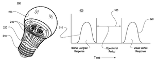
- a graph 500 illustrating an operational period of a lighting system according to an embodiment of the invention is depicted.
- a first plot 510 of the graph 500 is an approximate distribution of PC response times for humans. PC response time may be generally considered to be less than about 2 milliseconds.
- a second plot 520 of the graph 500 is an approximate distribution of visual cortex response times for humans. Visual cortex response time may be generally considered to be at least about 20 milliseconds.
- the operational period range may be from about 2 milliseconds to about 20 milliseconds. In some embodiments, the operational period may be about 20 milliseconds, about 16.67 milliseconds, about 10 millisecond, about 8.33 milliseconds, about 6.67 milliseconds, about 5.56 milliseconds, about 5 milliseconds, about 4.17 milliseconds, about 3.33 milliseconds, or about 2.22 milliseconds.
- a light source that emits a first light for a length of time that falls within the operational period range 530 will be discretely perceived by PCs and transmitted to the visual cortex.
- the first light may be a light having a wavelength range that corresponds to a wavelength range that a photoreceptor cell of a human, such as, for example, a cone cell, will respond to.
- a light source that emits a subsequent second light for a length of time that similarly falls within the operational period range 530 will also be discretely perceived by PCs.
- the second light may be a light having a wavelength range that corresponds to a wavelength range that a photoreceptor cell of a human, such as a cone cell, will respond to.
- the particular type of photoreceptor cell that responds to the second light may be different than the type of photoreceptor cell that responds to the first light, as described hereinabove.
- the visual cortex will perceive the lights in a combined fashion, perceiving the lights as a combined light.
- the characteristics of the combined light may be such that the wavelengths of each of the first light and the second light, each corresponding to a color, may be combined to form a functional equivalent of a metamer, the metamer having an apparent color that is approximately a blend, combination, or average of the colors of each of the first and second lights.
- the brightness of the combined light will not be compressed by PCs, as only a single type of photoreceptor cell will be active at a given time. Accordingly, the perceived brightness of the combined light may be approximated by plot 320 of FIG. 3 , representing an increase in perceived brightness over a lighting system where the first light and the second light are emitted concurrently, as approximated by plot 310 .
- the controller of the driver circuit of the PCB 260 may be configured to operate the light sources 240 to have a duty cycle that is within the operational period range 530 as represented in FIG. 5 . More specifically, the controller may be configured to operate the first light source 240 ′ with a duty cycle that is within the operational period range 530 . Moreover, the first light source 240 ′ may be configured to emit light having a wavelength range that corresponds to a wavelength range that a photoreceptor cell may respond to. For example, the first light source 240 ′ may emit a light having a wavelength range corresponding to a generally green light. Accordingly, medium cone cells of an observer may respond to the light emitted by the first light source 240 ′. Furthermore, the second light source 240 ′′ may emit a light having a wavelength range corresponding to a generally blue light source. Accordingly, small cone cells of an observer may respond to the light emitted by the second light source 240 ′′.
- each of the first light source 240 ′ and the second light source 240 ′′ may emit light having a wavelength range corresponding to any color of the visible spectrum.
- the light sources 240 may be configured to emit monochromatic light.
- the light sources 240 may be configured to emit monochromatic light corresponding to wavelength ranges that a photoreceptor cell may respond to.
- the light sources 240 may be configured to emit polychromatic light.
- the light sources 240 may be configured to emit polychromatic light including a constituent light having a wavelength range corresponding to wavelength ranges that a photoreceptor cell may respond to.
- the controller may be functionally coupled to light sources 240 configured to emit polychromatic light such that the controller may selectively operate the light sources 240 to emit light having a wavelength range corresponding to a wavelength range that a photoreceptor cell may respond to.
- the lamp 200 may include any number of light sources 240 , and the depiction of the lamp 200 including two light sources 240 ′, 240 ′′ is exemplary only and does not limit the scope of the invention.
- the lamp 200 may include a third light source (not shown), wherein the first light source 240 ′ is configured to emit monochromatic light having a wavelength range, such as a wavelength range corresponding to generally red light, corresponding to a wavelength range to which a first photoreceptor cell, such as a long-type cone cell, may be responsive to.
- the second light source 240 ′′ may be configured to emit monochromatic light having a wavelength range, such as a wavelength range corresponding to generally green light, corresponding to a wavelength range to which a second photoreceptor cell, such as a medium-type cone cell, may be responsive to.
- the third light source may be configured to emit monochromatic light having a wavelength range, such as a wavelength range corresponding to a generally blue light, corresponding to a wavelength range to which a third photoreceptor cell, such as a short-type cone cell, may be responsive to.
- the controller may be functionally coupled to each of the first light source 240 ′, the second light source 240 ′′, and the third light source so as to alternately operate each of the light sources 240 with a duty cycle within the operational period range 530 .
- the controller may be configured to selectively operate the light sources 240 to alter, manipulate, or otherwise change the characteristic of light emitted by each of the light sources 240 , and hence by the lamp 200 .
- the controller may alter the average luminous intensity of light emitted by the light sources 240 so as to alter the perceived brightness of light emitted by the lamp 200 .
- the controller may employ pulse width modulation (PWM) to generally reduce the luminous intensity of light emitted by the light sources 240 to reduce the luminous intensity from a maximum luminous intensity, thereby reducing the perceived brightness of the light emitted by the lamp 200 .
- PWM pulse width modulation
- the lamp may vary the duty cycle of the various light sources 240 such that a light source 240 of a certain color may be greater than the duty cycle of another light source 240 of a different color, thereby affecting the perceived color of the light emitted by the lamp 200 .
- the light sources 240 may be configured to emit a generally white light when operated according to a first proportion of duty cycles for each of the light sources 240 , and may include a red light source and a blue light source.
- the white light may have associated with it a color temperature.
- the controller may be configured to generally reduce the color temperature of the white light by increasing the duty cycle of the red light source relative to the duty cycle of the other light sources 240 .
- the controller may be configured to increase the color temperature of the white light by increasing the duty cycle of the blue light source relative to the duty cycle of the other light sources 240 .
- the first proportion of duty cycles may generate a white light having a color temperature of about 6000 Kelvin.
- the first proportion of duty cycles may generate a white light having a color temperature of about 2000 Kelvin, about 2500 Kelvin, about 2700 Kelvin, about 2800 Kelvin, about 2900 Kelvin, about 3000 Kelvin, about 3100 Kelvin, about 3200 Kelvin, about 3300 Kelvin, about 3350 Kelvin, about 3500 Kelvin, about 4000 Kelvin, about 4500 Kelvin, about 5000 Kelvin, or about 5500 Kelvin.
- the PCB 260 may be configured to be positioned at least partially within and carried by each of the housing 250 and the heat sink 220 .
- the housing 250 may be configured to be positioned at least partially within and carried by each of the base 210 and the heat sink 220 .
- the heat sink 220 may be configured to facilitate the positioning of the light sources 240 thereupon.
- the holder 290 may be configured to cooperate with the heat sink 220 to secure the light sources 240 , preventing movement of the light sources 240 relative to the other elements of the lamp 200 .
- Each of the heat sink 220 and the holder 290 may be configured to cooperate with the screws 280 to further facilitate the securing of the light sources 240 .
- any securing device including fasteners, welding, adhesives, and the likes, may be used in securing the light sources 240 , and each of the heat sink 220 and the holder 290 may be configured to cooperate therewith.
- the spring wire connectors 270 may be configured to place the light sources 240 in electrical communication with the PCB 260 and its constituent elements.
- the spring wire connectors 270 may be configured to facilitate electrical connection between the circuitry of the PCB 260 and the light sources 240 .
- the method of emitting light to which certain types of photoreceptor cells respond to may be applied to lighting devices other than lamps, luminaires, or other conventional lighting devices.
- a device that is configured to emit light having varying colors may be configured to emit light having reduced PC compression.
- Such devices may include, without limitation, displays, such as computerized device displays, display adaptors, projectors, and any other device that is capable of emitting light. More specifically, devices that rely on emitting light to convey information across a visible medium are included within the scope of the invention.
- the invention may be employed by a device that relies on backlighting, edge lighting, or any other supplemental light source to increase the brightness of the device, so long as the device is capable of emitting light having a color that one type of photoreceptor cell is responsive to.
- the visual display 610 may be any type of display device for conveying information in a visual mode known in the art, including, but not limited to, liquid crystal displays, light-emitting diode displays, organic light-emitting diode displays, cathode ray tube displays, electroluminescent displays, surface-conduction electron-emitter displays, interferometric modular displays, quantum dot displays, carbon nanotube displays, laser displays, digital micromirror device displays, plasma displays, and any other type of display known in the art.
- the visual display 610 may be a liquid crystal display comprising a plurality of pixels, each pixel being capable of emitting light within a wavelength range corresponding to a wavelength range a photoreceptor cell is responsive to. Additionally, each pixel may be capable of emitting light and terminate emitting light within the operational range demonstrate by element 530 in FIG. 5 .
- the display device 600 may further include a display device adaptor 620 configured to control the operation of the visual display 610 .
- the display device adaptor 620 is depicted as being separate and apart from the visual display 610 and electrically connected thereto. It is appreciated that in some embodiments the visual display 610 and the display device adaptor 620 may be integrated into a single structural element.
- the display device adaptor 620 may be in communication with and able to selectively operate each of the pixels of the visual display 610 .
- the display device adaptor 620 may determine which parts of the received visual information may be subject to physioneural compression, such as colors that are color opponents.
- the display adaptor may then operate the related plurality of pixels of the visual display 610 to emit a sequence of two or more lights having a wavelength associated with a responsive wavelength range of two or more photoreceptor cells, as described hereinabove and hereinbelow.
- the visual information depicted by the light emitted by the visual display 610 will accurately represent the information received by the display device adaptor 620 while not having a reduced perceived brightness due to physioneural compression.
- the method 700 illustrates a method of operating a lighting device to emit light to have a perceived brightness as shown by plot 320 in FIG. 3 .
- the method begins at Block 710 .
- the lighting device may emit a first light for a first period.
- the first light may be operated for a first period of time to have a duty cycle corresponding to the operational period range as described by element 530 in FIG. 5 . That is to say, the first light may emit light for a period of time longer than the response time of physioneural cells, but shorter than the response time of a visual cortex.
- the first light may emit a monochromatic light having a wavelength range within a range of wavelengths corresponding to a wavelength range a photoreceptor cell may respond to.
- the method may continue at Block 730 , where the lighting device may emit a second light for a second period.
- the second period may be a length of time corresponding to the operational period range.
- the second light may emit a monochromatic light having a wavelength range within a range of wavelengths corresponding to a wavelength range a photoreceptor cell may respond to.
- the second light may cause a response in a type of photoreceptor cell that is different from the type of photoreceptor cell that responds to the first light.
- the lighting device may determine whether to continue to emit light. This determination may be performed by the circuitry, which may include a controller, as described for the lamp 200 hereinabove. The determination may be made based upon the continued reception of electrical power to the lighting device by an external power source. In other embodiments, the determination may be made based upon a communication received by the lighting device. In such embodiments, the lighting device may include communication circuitry necessary to accomplish such communication, such as that described in U.S. patent application Ser. No. 13/463,020 titled “Wireless Pairing System and Associated Methods” filed May 3, 2012, the content of which is incorporated herein in its entirety by reference. If it is determined that the lighting device will continue emitting light, then the method may return to Block 720 . If it is determined the lighting device will not continue emitting light, the method may end at Block 750 .
- a lighting system may be configured to include a latency period between the sequential emissions of light from light sources.
- the lighting system may be a lighting device as described hereinabove.
- the latency period may be characterized as a period during which none of the light sources of the lighting system are operated to emit light.
- An object of including such a latency period is to permit an PC of an observer of light emitted by the lighting system to cease transmitting to the visual cortex light information related to the light previously emitted by the lighting system.
- the lighting device may operate a light source to emit a subsequent light.
- the discharge time of PCs may be generally considered to be about 50 nanoseconds.
- the second light may emit a monochromatic light having a wavelength range within a range of wavelengths corresponding to a wavelength range a photoreceptor cell may respond to.
- the second light may cause a response in a type of photoreceptor cell that is different from the type of photoreceptor cell that responds to the first light.
- a lighting system may be a lighting device including three light sources. Each of the light sources may be configured to emit light within a wavelength range corresponding to a wavelength range to which a photoreceptor cell may be responsive to.
- the first light source may be configured to emit light having a wavelength range corresponding to a generally red color, corresponding to a wavelength range that long-type cone cells are responsive to
- the second light source may emit light having a wavelength range corresponding to a generally green color, corresponding to a wavelength range that medium-type cone cells are responsive to
- the third light source may emit lighting having a wavelength range corresponding to a generally blue color, corresponding to a wavelength range that short-type cone cells are responsive to.
- the method 900 may start at Block 910 .
- the lighting device may operate the first light source to emit a first light for a first period.
- the first period may be within the operational period range as described hereinabove.
- the method may then continue at Block 930 , where the lighting device may operate the second light source to emit a second light for a second period.
- the second period may similarly be within the operational period as described hereinabove.
- the method may then continue at Block 940 , where the lighting device may operate the third light source to emit a third light for a third period. Again, the third period may be within the operational period as described hereinabove.
- each of the first period, the second period, and third period may be approximately equal, or they may be different, while still being within the operational period range.
- the lighting device may selectively vary the first, second, and third periods to alter the color of light perceived by the visual cortex, wherein the longer the period is, the perceived color appears to be more closely related to the color of light associated with the period. For example, if the first period is relatively longer than either of the second period and the third period, the combined light, as described hereinabove, will appear to be redder in color. Accordingly, the color of the combined light may be controlled according to the principles of additive colors, as known in the art.
- the method may continue at Block 950 , where the lighting device may determine whether to continue to emit light. This determination may be performed by the circuitry, which may include a controller, as described for the lamp 200 hereinabove. If it is determined that the lighting device will continue emitting light, then the method may continue by returning to Block 920 . If, however, it is determined the lighting device will not continue emitting light, then the method may end at Block 960 .
- a lighting system may be configured to include a latency period between the subsequent emissions of light from light sources.
- the lighting system of the present embodiment may be similar to that of the embodiment presented in FIG. 9 , wherein the lighting system may be a lighting device including three light sources.
- Each of the light sources may be configured to emit light within a wavelength range corresponding to a wavelength range to which a photoreceptor cell may be responsive to.
- the first light source may be configured to emit light having a wavelength range corresponding to a generally red color, corresponding to a wavelength range that long-type cone cells are responsive to
- the second light source may emit light having a wavelength range corresponding to a generally green color, corresponding to a wavelength range that medium-type cone cells are responsive to
- the third light source may emit lighting having a wavelength range corresponding to a generally blue color, corresponding to a wavelength range that short-type cone cells are responsive to.
- the lighting system of the present embodiment may be configured to include a latency period between operation of each of the lighting devices, as described hereinabove, specifically in describing the embodiment presented in FIG. 8 .
- the method 1000 may start at Block 1010 .
- the lighting device may operate the first light source to emit a first light for a first period.
- the first period may be within the operational period range as described hereinabove.
- the method 1000 may then continue at Block 1030 , where the lighting device may then enter a latency period during which the lighting device does not operate any light source of the lighting device, causing the lighting device to emit no light.
- the latency period may be characterized the same as the latency period presented in FIG. 8 .
- the method 1000 may then continue at Block 1040 , where the lighting device may operate the second light source to emit a second light for a second period.
- the method 1000 may continue at Block 1050 , where the lighting device enters another latency period.
- the method 1000 may continue yet further at Block 1060 , where the lighting device may operate the third light source to emit a third light for a third period.
- Each of the first, second, and third light periods may be of varying lengths, as described hereinabove.
- the method 1000 may continue at Block 1070 , where the lighting device may determine whether to continue to emit light. This determination may be performed by the circuitry, which may include a controller, as described for the lamp 200 hereinabove. If it is determined that the lighting device will continue emitting light, then the method 1000 may continue at Block 1080 , where the lighting device may enter another latency period. The method 1000 may then return to Block 1020 . If, however, it is determined at Block 1070 the lighting device will not continue emitting light, the method may end at Block 1090 .
Abstract
Description
B=L0.6,
which is represented by
which is represented by
Claims (18)
Priority Applications (9)
| Application Number | Priority Date | Filing Date | Title |
|---|---|---|---|
| US13/830,390 US9018854B2 (en) | 2013-03-14 | 2013-03-14 | Lighting system with reduced physioneural compression and associate methods |
| CN201480027860.2A CN105228697B (en) | 2013-03-14 | 2014-03-12 | Reduce the illuminator and correlation technique of physiology nerve compression |
| EP14731408.2A EP2968971B1 (en) | 2013-03-14 | 2014-03-12 | Lighting system with reduced physioneural compression and associated methods |
| BR112015023442A BR112015023442A2 (en) | 2013-03-14 | 2014-03-12 | lighting system with reduced physical and neural compression and associated methods |
| JP2016501543A JP6320507B2 (en) | 2013-03-14 | 2014-03-12 | Illumination system and associated method with reduced physiological nerve compression |
| PCT/US2014/024459 WO2014159618A1 (en) | 2013-03-14 | 2014-03-12 | Lighting system with reduced physioneural compression and associated methods |
| KR1020157029401A KR101720725B1 (en) | 2013-03-14 | 2014-03-12 | Lighting system with reduced physioneural compression and associated methods |
| CA2906451A CA2906451C (en) | 2013-03-14 | 2014-03-12 | Lighting system with reduced physioneural compression and associated methods |
| HK16101085.6A HK1215208A1 (en) | 2013-03-14 | 2016-01-29 | Lighting system with reduced physioneural compression and associated methods |
Applications Claiming Priority (1)
| Application Number | Priority Date | Filing Date | Title |
|---|---|---|---|
| US13/830,390 US9018854B2 (en) | 2013-03-14 | 2013-03-14 | Lighting system with reduced physioneural compression and associate methods |
Publications (2)
| Publication Number | Publication Date |
|---|---|
| US20140265937A1 US20140265937A1 (en) | 2014-09-18 |
| US9018854B2 true US9018854B2 (en) | 2015-04-28 |
Family
ID=50977042
Family Applications (1)
| Application Number | Title | Priority Date | Filing Date |
|---|---|---|---|
| US13/830,390 Active 2033-05-08 US9018854B2 (en) | 2013-03-14 | 2013-03-14 | Lighting system with reduced physioneural compression and associate methods |
Country Status (9)
| Country | Link |
|---|---|
| US (1) | US9018854B2 (en) |
| EP (1) | EP2968971B1 (en) |
| JP (1) | JP6320507B2 (en) |
| KR (1) | KR101720725B1 (en) |
| CN (1) | CN105228697B (en) |
| BR (1) | BR112015023442A2 (en) |
| CA (1) | CA2906451C (en) |
| HK (1) | HK1215208A1 (en) |
| WO (1) | WO2014159618A1 (en) |
Citations (88)
| Publication number | Priority date | Publication date | Assignee | Title |
|---|---|---|---|---|
| US5523878A (en) | 1994-06-30 | 1996-06-04 | Texas Instruments Incorporated | Self-assembled monolayer coating for micro-mechanical devices |
| US5680230A (en) | 1993-09-09 | 1997-10-21 | Canon Kabushiki Kaisha | Image processing method and apparatus thereof |
| US5704701A (en) | 1992-03-05 | 1998-01-06 | Rank Brimar Limited | Spatial light modulator system |
| US5997150A (en) | 1995-10-25 | 1999-12-07 | Texas Instruments Incorporated | Multiple emitter illuminator engine |
| US6140646A (en) | 1998-12-17 | 2000-10-31 | Sarnoff Corporation | Direct view infrared MEMS structure |
| US6341876B1 (en) | 1997-02-19 | 2002-01-29 | Digital Projection Limited | Illumination system |
| US6356700B1 (en) | 1998-06-08 | 2002-03-12 | Karlheinz Strobl | Efficient light engine systems, components and methods of manufacture |
| US6594090B2 (en) | 2001-08-27 | 2003-07-15 | Eastman Kodak Company | Laser projection display system |
| US20040052076A1 (en) | 1997-08-26 | 2004-03-18 | Mueller George G. | Controlled lighting methods and apparatus |
| US6767111B1 (en) | 2003-02-26 | 2004-07-27 | Kuo-Yen Lai | Projection light source from light emitting diodes |
| US6817735B2 (en) | 2001-05-24 | 2004-11-16 | Matsushita Electric Industrial Co., Ltd. | Illumination light source |
| US6870523B1 (en) | 2000-06-07 | 2005-03-22 | Genoa Color Technologies | Device, system and method for electronic true color display |
| US6871982B2 (en) | 2003-01-24 | 2005-03-29 | Digital Optics International Corporation | High-density illumination system |
| US6974713B2 (en) | 2000-08-11 | 2005-12-13 | Reflectivity, Inc. | Micromirrors with mechanisms for enhancing coupling of the micromirrors with electrostatic fields |
| US20060002110A1 (en) | 2004-03-15 | 2006-01-05 | Color Kinetics Incorporated | Methods and systems for providing lighting systems |
| US20060002108A1 (en) | 2004-06-30 | 2006-01-05 | Ouderkirk Andrew J | Phosphor based illumination system having a short pass reflector and method of making same |
| US7072096B2 (en) | 2001-12-14 | 2006-07-04 | Digital Optics International, Corporation | Uniform illumination system |
| US7075707B1 (en) | 1998-11-25 | 2006-07-11 | Research Foundation Of The University Of Central Florida, Incorporated | Substrate design for optimized performance of up-conversion phosphors utilizing proper thermal management |
| US20060164005A1 (en) | 2005-01-25 | 2006-07-27 | Chuan-Sheng Sun | Illumination apparatus having adjustable color temperature and method for adjusting the color temperature |
| US7083304B2 (en) | 2003-08-01 | 2006-08-01 | Illumination Management Solutions, Inc. | Apparatus and method of using light sources of differing wavelengths in an unitized beam |
| US7125142B2 (en) * | 2003-05-06 | 2006-10-24 | Harry Lee Wainwright | Flame simulating device |
| US20060285193A1 (en) | 2005-06-03 | 2006-12-21 | Fuji Photo Film Co., Ltd. | Optical modulation element array |
| US20070013871A1 (en) | 2005-07-15 | 2007-01-18 | Marshall Stephen W | Light-emitting diode (LED) illumination in display systems using spatial light modulators (SLM) |
| US7178941B2 (en) | 2003-05-05 | 2007-02-20 | Color Kinetics Incorporated | Lighting methods and systems |
| US20070159492A1 (en) | 2006-01-11 | 2007-07-12 | Wintek Corporation | Image processing method and pixel arrangement used in the same |
| US7246923B2 (en) | 2004-02-11 | 2007-07-24 | 3M Innovative Properties Company | Reshaping light source modules and illumination systems using the same |
| US7255469B2 (en) | 2004-06-30 | 2007-08-14 | 3M Innovative Properties Company | Phosphor based illumination system having a light guide and an interference reflector |
| US7261453B2 (en) | 2005-01-25 | 2007-08-28 | Morejon Israel J | LED polarizing optics for color illumination system and method of using same |
| US7289090B2 (en) | 2003-12-10 | 2007-10-30 | Texas Instruments Incorporated | Pulsed LED scan-ring array for boosting display system lumens |
| US7300177B2 (en) | 2004-02-11 | 2007-11-27 | 3M Innovative Properties | Illumination system having a plurality of light source modules disposed in an array with a non-radially symmetrical aperture |
| US7303291B2 (en) | 2004-03-31 | 2007-12-04 | Sanyo Electric Co., Ltd. | Illumination apparatus and video projection display system |
| US7325956B2 (en) | 2005-01-25 | 2008-02-05 | Jabil Circuit, Inc. | Light-emitting diode (LED) illumination system for a digital micro-mirror device (DMD) and method of providing same |
| US7342658B2 (en) | 2005-12-28 | 2008-03-11 | Eastman Kodak Company | Programmable spectral imaging system |
| US7349095B2 (en) | 2005-05-19 | 2008-03-25 | Casio Computer Co., Ltd. | Light source apparatus and projection apparatus |
| US20080143973A1 (en) | 2006-10-12 | 2008-06-19 | Jing Miau Wu | Light source device of laser LED and projector having the same device |
| US20080198572A1 (en) | 2007-02-21 | 2008-08-21 | Medendorp Nicholas W | LED lighting systems including luminescent layers on remote reflectors |
| US20080232084A1 (en) | 2007-03-19 | 2008-09-25 | Nec Lighting, Ltd | White light source device |
| US7429983B2 (en) | 2005-11-01 | 2008-09-30 | Cheetah Omni, Llc | Packet-based digital display system |
| US7436996B2 (en) | 2001-06-07 | 2008-10-14 | Genoa Color Technologies Ltd | Device, system and method of data conversion for wide gamut displays |
| US7434946B2 (en) | 2005-06-17 | 2008-10-14 | Texas Instruments Incorporated | Illumination system with integrated heat dissipation device for use in display systems employing spatial light modulators |
| US7438443B2 (en) | 2003-09-19 | 2008-10-21 | Ricoh Company, Limited | Lighting device, image-reading device, color-document reading apparatus, image-forming apparatus, projection apparatus |
| WO2008146220A2 (en) | 2007-05-25 | 2008-12-04 | Koninklijke Philips Electronics N.V. | A lighting system for creating a biological effect |
| US7476016B2 (en) | 2005-06-28 | 2009-01-13 | Seiko Instruments Inc. | Illuminating device and display device including the same |
| WO2009023968A1 (en) | 2007-08-20 | 2009-02-26 | UNIVERSITé LAVAL | Artificial light apparatus and its use for influencing a condition in a subject |
| US20090059585A1 (en) | 2007-08-29 | 2009-03-05 | Young Optics Inc. | Illumination system |
| US7530708B2 (en) | 2004-10-04 | 2009-05-12 | Lg Electronics Inc. | Surface emitting light source and projection display device using the same |
| US20090128781A1 (en) | 2006-06-13 | 2009-05-21 | Kenneth Li | LED multiplexer and recycler and micro-projector incorporating the Same |
| US7540616B2 (en) | 2005-12-23 | 2009-06-02 | 3M Innovative Properties Company | Polarized, multicolor LED-based illumination source |
| US7556406B2 (en) | 2003-03-31 | 2009-07-07 | Lumination Llc | Led light with active cooling |
| US7598686B2 (en) | 1997-12-17 | 2009-10-06 | Philips Solid-State Lighting Solutions, Inc. | Organic light emitting diode methods and apparatus |
| US7598961B2 (en) | 2003-10-21 | 2009-10-06 | Samsung Electronics Co., Ltd. | method and apparatus for converting from a source color space to a target color space |
| WO2009121539A1 (en) | 2008-03-31 | 2009-10-08 | Tridonicatco Schweiz Ag | System and method for controlling leds |
| US7626755B2 (en) | 2007-01-31 | 2009-12-01 | Panasonic Corporation | Wavelength converter and two-dimensional image display device |
| US20100006762A1 (en) | 2007-03-27 | 2010-01-14 | Kabushiki Kaisha Toshiba | Scintillator panel and radiation detector |
| US7677736B2 (en) | 2004-02-27 | 2010-03-16 | Panasonic Corporation | Illumination light source and two-dimensional image display using same |
| US7684007B2 (en) | 2004-08-23 | 2010-03-23 | The Boeing Company | Adaptive and interactive scene illumination |
| US7703943B2 (en) | 2007-05-07 | 2010-04-27 | Intematix Corporation | Color tunable light source |
| US7705810B2 (en) | 2003-05-07 | 2010-04-27 | Samsung Electronics Co., Ltd. | Four-color data processing system |
| US7709811B2 (en) | 2007-07-03 | 2010-05-04 | Conner Arlie R | Light emitting diode illumination system |
| CN101702421A (en) | 2009-10-23 | 2010-05-05 | 中外合资江苏稳润光电有限公司 | Manufacturing method of white light LED |
| US7719766B2 (en) | 2007-06-20 | 2010-05-18 | Texas Instruments Incorporated | Illumination source and method therefor |
| US7728846B2 (en) | 2003-10-21 | 2010-06-01 | Samsung Electronics Co., Ltd. | Method and apparatus for converting from source color space to RGBW target color space |
| US7766490B2 (en) | 2006-12-13 | 2010-08-03 | Philips Lumileds Lighting Company, Llc | Multi-color primary light generation in a projection system using LEDs |
| US20100202129A1 (en) | 2009-01-21 | 2010-08-12 | Abu-Ageel Nayef M | Illumination system utilizing wavelength conversion materials and light recycling |
| US20100231863A1 (en) | 2007-10-08 | 2010-09-16 | Koninklijke Philips Electronics N.V. | Lighting device, array of lighting devices and optical projection device |
| US20100244700A1 (en) | 2007-12-24 | 2010-09-30 | Patrick Chong | System for Representing Colors Including an Integrating Light Capsule |
| WO2010122446A1 (en) | 2009-04-16 | 2010-10-28 | Koninklijke Philips Electronics N.V. | Illumination device and method for reducing sleep inertia or controlling alertness |
| US7828453B2 (en) | 2009-03-10 | 2010-11-09 | Nepes Led Corporation | Light emitting device and lamp-cover structure containing luminescent material |
| US7834867B2 (en) | 2006-04-11 | 2010-11-16 | Microvision, Inc. | Integrated photonics module and devices using integrated photonics modules |
| US7832878B2 (en) | 2006-03-06 | 2010-11-16 | Innovations In Optics, Inc. | Light emitting diode projection system |
| US20100315320A1 (en) | 2007-12-07 | 2010-12-16 | Sony Corporation | Light source device and display device |
| US20100320928A1 (en) | 2008-02-13 | 2010-12-23 | Canon Components, Inc. | White light emitting apparatus and line illuminator using the same in image reading apparatus |
| US20100321641A1 (en) | 2008-02-08 | 2010-12-23 | Koninklijke Philips Electronics N.V. | Light module device |
| US8016443B2 (en) | 2008-05-02 | 2011-09-13 | Light Prescriptions Innovators, Llc | Remote-phosphor LED downlight |
| US8049763B2 (en) | 2007-08-13 | 2011-11-01 | Samsung Electronics Co., Ltd. | RGB to RGBW color decomposition method and system |
| US8047660B2 (en) | 2005-09-13 | 2011-11-01 | Texas Instruments Incorporated | Projection system and method including spatial light modulator and compact diffractive optics |
| WO2011141842A1 (en) | 2010-05-14 | 2011-11-17 | Koninklijke Philips Electronics N.V. | System for providing light therapy to a subject using two or more wavelength bands of electromagnetic radiation |
| US20110310446A1 (en) | 2010-06-21 | 2011-12-22 | Ricoh Company, Limited | Image forming apparatus, color adjustment method, and computer program product |
| US8083378B2 (en) * | 2007-09-18 | 2011-12-27 | Seiko Epson Corporation | Single color LED clusters for image generation |
| US8083364B2 (en) | 2008-12-29 | 2011-12-27 | Osram Sylvania Inc. | Remote phosphor LED illumination system |
| US8096668B2 (en) | 2008-01-16 | 2012-01-17 | Abu-Ageel Nayef M | Illumination systems utilizing wavelength conversion materials |
| US8212836B2 (en) | 2008-02-15 | 2012-07-03 | Panasonic Corporation | Color management module, color management apparatus, integrated circuit, display unit, and method of color management |
| US8297783B2 (en) | 2008-09-10 | 2012-10-30 | Samsung Electronics Co., Ltd. | Light emitting device and system providing white light with various color temperatures |
| US20120286700A1 (en) | 2011-05-15 | 2012-11-15 | Lighting Science Group Corporation | High efficacy lighting signal converter and associated methods |
| US8331099B2 (en) | 2006-06-16 | 2012-12-11 | Robert Bosch Gmbh | Method for fixing an electrical or an electronic component, particularly a printed-circuit board, in a housing and fixing element therefor |
| US8337029B2 (en) | 2008-01-17 | 2012-12-25 | Intematix Corporation | Light emitting device with phosphor wavelength conversion |
| US8581520B1 (en) * | 2012-05-14 | 2013-11-12 | Usai, Llc | Lighting system having a dimming color simulating an incandescent light |
| US8742695B2 (en) * | 2012-05-14 | 2014-06-03 | Usai, Llc | Lighting control system and method |
Family Cites Families (5)
| Publication number | Priority date | Publication date | Assignee | Title |
|---|---|---|---|---|
| JP3785768B2 (en) * | 1997-11-27 | 2006-06-14 | セイコーエプソン株式会社 | Image forming system and projection display device |
| JPH11195373A (en) * | 1998-01-06 | 1999-07-21 | Matsushita Electric Ind Co Ltd | Light source and display device |
| US7319293B2 (en) | 2004-04-30 | 2008-01-15 | Lighting Science Group Corporation | Light bulb having wide angle light dispersion using crystalline material |
| CN101480104B (en) * | 2006-06-23 | 2011-03-09 | 皇家飞利浦电子股份有限公司 | Method and device for driving an array of light sources |
| RU2569707C2 (en) * | 2010-01-21 | 2015-11-27 | Конинклейке Филипс Электроникс Н.В. | Control device, portable device and illuminating system for phototherapeutic purposes |
-
2013
- 2013-03-14 US US13/830,390 patent/US9018854B2/en active Active
-
2014
- 2014-03-12 CN CN201480027860.2A patent/CN105228697B/en not_active Expired - Fee Related
- 2014-03-12 CA CA2906451A patent/CA2906451C/en active Active
- 2014-03-12 WO PCT/US2014/024459 patent/WO2014159618A1/en active Application Filing
- 2014-03-12 JP JP2016501543A patent/JP6320507B2/en not_active Expired - Fee Related
- 2014-03-12 BR BR112015023442A patent/BR112015023442A2/en not_active IP Right Cessation
- 2014-03-12 EP EP14731408.2A patent/EP2968971B1/en not_active Not-in-force
- 2014-03-12 KR KR1020157029401A patent/KR101720725B1/en active IP Right Grant
-
2016
- 2016-01-29 HK HK16101085.6A patent/HK1215208A1/en not_active IP Right Cessation
Patent Citations (94)
| Publication number | Priority date | Publication date | Assignee | Title |
|---|---|---|---|---|
| US5704701A (en) | 1992-03-05 | 1998-01-06 | Rank Brimar Limited | Spatial light modulator system |
| US5680230A (en) | 1993-09-09 | 1997-10-21 | Canon Kabushiki Kaisha | Image processing method and apparatus thereof |
| US5523878A (en) | 1994-06-30 | 1996-06-04 | Texas Instruments Incorporated | Self-assembled monolayer coating for micro-mechanical devices |
| US5997150A (en) | 1995-10-25 | 1999-12-07 | Texas Instruments Incorporated | Multiple emitter illuminator engine |
| US6341876B1 (en) | 1997-02-19 | 2002-01-29 | Digital Projection Limited | Illumination system |
| US20040052076A1 (en) | 1997-08-26 | 2004-03-18 | Mueller George G. | Controlled lighting methods and apparatus |
| US7845823B2 (en) | 1997-08-26 | 2010-12-07 | Philips Solid-State Lighting Solutions, Inc. | Controlled lighting methods and apparatus |
| US7598686B2 (en) | 1997-12-17 | 2009-10-06 | Philips Solid-State Lighting Solutions, Inc. | Organic light emitting diode methods and apparatus |
| US6356700B1 (en) | 1998-06-08 | 2002-03-12 | Karlheinz Strobl | Efficient light engine systems, components and methods of manufacture |
| US7075707B1 (en) | 1998-11-25 | 2006-07-11 | Research Foundation Of The University Of Central Florida, Incorporated | Substrate design for optimized performance of up-conversion phosphors utilizing proper thermal management |
| US6140646A (en) | 1998-12-17 | 2000-10-31 | Sarnoff Corporation | Direct view infrared MEMS structure |
| US6870523B1 (en) | 2000-06-07 | 2005-03-22 | Genoa Color Technologies | Device, system and method for electronic true color display |
| US6974713B2 (en) | 2000-08-11 | 2005-12-13 | Reflectivity, Inc. | Micromirrors with mechanisms for enhancing coupling of the micromirrors with electrostatic fields |
| US6817735B2 (en) | 2001-05-24 | 2004-11-16 | Matsushita Electric Industrial Co., Ltd. | Illumination light source |
| US7436996B2 (en) | 2001-06-07 | 2008-10-14 | Genoa Color Technologies Ltd | Device, system and method of data conversion for wide gamut displays |
| US6594090B2 (en) | 2001-08-27 | 2003-07-15 | Eastman Kodak Company | Laser projection display system |
| US7072096B2 (en) | 2001-12-14 | 2006-07-04 | Digital Optics International, Corporation | Uniform illumination system |
| US7400439B2 (en) | 2001-12-14 | 2008-07-15 | Digital Optics International Corporation | Uniform illumination system |
| US6871982B2 (en) | 2003-01-24 | 2005-03-29 | Digital Optics International Corporation | High-density illumination system |
| US7520642B2 (en) | 2003-01-24 | 2009-04-21 | Digital Optics International Corporation | High-density illumination system |
| US6767111B1 (en) | 2003-02-26 | 2004-07-27 | Kuo-Yen Lai | Projection light source from light emitting diodes |
| US7556406B2 (en) | 2003-03-31 | 2009-07-07 | Lumination Llc | Led light with active cooling |
| US7178941B2 (en) | 2003-05-05 | 2007-02-20 | Color Kinetics Incorporated | Lighting methods and systems |
| US7125142B2 (en) * | 2003-05-06 | 2006-10-24 | Harry Lee Wainwright | Flame simulating device |
| US7705810B2 (en) | 2003-05-07 | 2010-04-27 | Samsung Electronics Co., Ltd. | Four-color data processing system |
| US7083304B2 (en) | 2003-08-01 | 2006-08-01 | Illumination Management Solutions, Inc. | Apparatus and method of using light sources of differing wavelengths in an unitized beam |
| US7438443B2 (en) | 2003-09-19 | 2008-10-21 | Ricoh Company, Limited | Lighting device, image-reading device, color-document reading apparatus, image-forming apparatus, projection apparatus |
| US7728846B2 (en) | 2003-10-21 | 2010-06-01 | Samsung Electronics Co., Ltd. | Method and apparatus for converting from source color space to RGBW target color space |
| US7598961B2 (en) | 2003-10-21 | 2009-10-06 | Samsung Electronics Co., Ltd. | method and apparatus for converting from a source color space to a target color space |
| US7289090B2 (en) | 2003-12-10 | 2007-10-30 | Texas Instruments Incorporated | Pulsed LED scan-ring array for boosting display system lumens |
| US7300177B2 (en) | 2004-02-11 | 2007-11-27 | 3M Innovative Properties | Illumination system having a plurality of light source modules disposed in an array with a non-radially symmetrical aperture |
| US7246923B2 (en) | 2004-02-11 | 2007-07-24 | 3M Innovative Properties Company | Reshaping light source modules and illumination systems using the same |
| US7677736B2 (en) | 2004-02-27 | 2010-03-16 | Panasonic Corporation | Illumination light source and two-dimensional image display using same |
| US20060002110A1 (en) | 2004-03-15 | 2006-01-05 | Color Kinetics Incorporated | Methods and systems for providing lighting systems |
| US7303291B2 (en) | 2004-03-31 | 2007-12-04 | Sanyo Electric Co., Ltd. | Illumination apparatus and video projection display system |
| US20060002108A1 (en) | 2004-06-30 | 2006-01-05 | Ouderkirk Andrew J | Phosphor based illumination system having a short pass reflector and method of making same |
| US7255469B2 (en) | 2004-06-30 | 2007-08-14 | 3M Innovative Properties Company | Phosphor based illumination system having a light guide and an interference reflector |
| US7684007B2 (en) | 2004-08-23 | 2010-03-23 | The Boeing Company | Adaptive and interactive scene illumination |
| US7530708B2 (en) | 2004-10-04 | 2009-05-12 | Lg Electronics Inc. | Surface emitting light source and projection display device using the same |
| US7261453B2 (en) | 2005-01-25 | 2007-08-28 | Morejon Israel J | LED polarizing optics for color illumination system and method of using same |
| US20060164005A1 (en) | 2005-01-25 | 2006-07-27 | Chuan-Sheng Sun | Illumination apparatus having adjustable color temperature and method for adjusting the color temperature |
| US7325956B2 (en) | 2005-01-25 | 2008-02-05 | Jabil Circuit, Inc. | Light-emitting diode (LED) illumination system for a digital micro-mirror device (DMD) and method of providing same |
| US7349095B2 (en) | 2005-05-19 | 2008-03-25 | Casio Computer Co., Ltd. | Light source apparatus and projection apparatus |
| US20060285193A1 (en) | 2005-06-03 | 2006-12-21 | Fuji Photo Film Co., Ltd. | Optical modulation element array |
| US7434946B2 (en) | 2005-06-17 | 2008-10-14 | Texas Instruments Incorporated | Illumination system with integrated heat dissipation device for use in display systems employing spatial light modulators |
| US7476016B2 (en) | 2005-06-28 | 2009-01-13 | Seiko Instruments Inc. | Illuminating device and display device including the same |
| US20070013871A1 (en) | 2005-07-15 | 2007-01-18 | Marshall Stephen W | Light-emitting diode (LED) illumination in display systems using spatial light modulators (SLM) |
| US8047660B2 (en) | 2005-09-13 | 2011-11-01 | Texas Instruments Incorporated | Projection system and method including spatial light modulator and compact diffractive optics |
| US7429983B2 (en) | 2005-11-01 | 2008-09-30 | Cheetah Omni, Llc | Packet-based digital display system |
| US7540616B2 (en) | 2005-12-23 | 2009-06-02 | 3M Innovative Properties Company | Polarized, multicolor LED-based illumination source |
| US7342658B2 (en) | 2005-12-28 | 2008-03-11 | Eastman Kodak Company | Programmable spectral imaging system |
| US20070159492A1 (en) | 2006-01-11 | 2007-07-12 | Wintek Corporation | Image processing method and pixel arrangement used in the same |
| US7832878B2 (en) | 2006-03-06 | 2010-11-16 | Innovations In Optics, Inc. | Light emitting diode projection system |
| US7834867B2 (en) | 2006-04-11 | 2010-11-16 | Microvision, Inc. | Integrated photonics module and devices using integrated photonics modules |
| US20090128781A1 (en) | 2006-06-13 | 2009-05-21 | Kenneth Li | LED multiplexer and recycler and micro-projector incorporating the Same |
| US8331099B2 (en) | 2006-06-16 | 2012-12-11 | Robert Bosch Gmbh | Method for fixing an electrical or an electronic component, particularly a printed-circuit board, in a housing and fixing element therefor |
| US20080143973A1 (en) | 2006-10-12 | 2008-06-19 | Jing Miau Wu | Light source device of laser LED and projector having the same device |
| US7766490B2 (en) | 2006-12-13 | 2010-08-03 | Philips Lumileds Lighting Company, Llc | Multi-color primary light generation in a projection system using LEDs |
| US7626755B2 (en) | 2007-01-31 | 2009-12-01 | Panasonic Corporation | Wavelength converter and two-dimensional image display device |
| US20080198572A1 (en) | 2007-02-21 | 2008-08-21 | Medendorp Nicholas W | LED lighting systems including luminescent layers on remote reflectors |
| US20080232084A1 (en) | 2007-03-19 | 2008-09-25 | Nec Lighting, Ltd | White light source device |
| US20100006762A1 (en) | 2007-03-27 | 2010-01-14 | Kabushiki Kaisha Toshiba | Scintillator panel and radiation detector |
| US7703943B2 (en) | 2007-05-07 | 2010-04-27 | Intematix Corporation | Color tunable light source |
| US8378574B2 (en) * | 2007-05-25 | 2013-02-19 | Koninklijke Philips Electronics N.V. | Lighting system for creating a biological effect |
| WO2008146220A2 (en) | 2007-05-25 | 2008-12-04 | Koninklijke Philips Electronics N.V. | A lighting system for creating a biological effect |
| US7719766B2 (en) | 2007-06-20 | 2010-05-18 | Texas Instruments Incorporated | Illumination source and method therefor |
| US7709811B2 (en) | 2007-07-03 | 2010-05-04 | Conner Arlie R | Light emitting diode illumination system |
| US8049763B2 (en) | 2007-08-13 | 2011-11-01 | Samsung Electronics Co., Ltd. | RGB to RGBW color decomposition method and system |
| WO2009023968A1 (en) | 2007-08-20 | 2009-02-26 | UNIVERSITé LAVAL | Artificial light apparatus and its use for influencing a condition in a subject |
| US20090059585A1 (en) | 2007-08-29 | 2009-03-05 | Young Optics Inc. | Illumination system |
| US8083378B2 (en) * | 2007-09-18 | 2011-12-27 | Seiko Epson Corporation | Single color LED clusters for image generation |
| US8556457B2 (en) * | 2007-09-18 | 2013-10-15 | Seiko Epson Corporation | Single color LED clusters for image generation |
| US20100231863A1 (en) | 2007-10-08 | 2010-09-16 | Koninklijke Philips Electronics N.V. | Lighting device, array of lighting devices and optical projection device |
| US20100315320A1 (en) | 2007-12-07 | 2010-12-16 | Sony Corporation | Light source device and display device |
| US20100244700A1 (en) | 2007-12-24 | 2010-09-30 | Patrick Chong | System for Representing Colors Including an Integrating Light Capsule |
| US8096668B2 (en) | 2008-01-16 | 2012-01-17 | Abu-Ageel Nayef M | Illumination systems utilizing wavelength conversion materials |
| US8337029B2 (en) | 2008-01-17 | 2012-12-25 | Intematix Corporation | Light emitting device with phosphor wavelength conversion |
| US20100321641A1 (en) | 2008-02-08 | 2010-12-23 | Koninklijke Philips Electronics N.V. | Light module device |
| US20100320928A1 (en) | 2008-02-13 | 2010-12-23 | Canon Components, Inc. | White light emitting apparatus and line illuminator using the same in image reading apparatus |
| US8212836B2 (en) | 2008-02-15 | 2012-07-03 | Panasonic Corporation | Color management module, color management apparatus, integrated circuit, display unit, and method of color management |
| WO2009121539A1 (en) | 2008-03-31 | 2009-10-08 | Tridonicatco Schweiz Ag | System and method for controlling leds |
| US8016443B2 (en) | 2008-05-02 | 2011-09-13 | Light Prescriptions Innovators, Llc | Remote-phosphor LED downlight |
| US8297783B2 (en) | 2008-09-10 | 2012-10-30 | Samsung Electronics Co., Ltd. | Light emitting device and system providing white light with various color temperatures |
| US8083364B2 (en) | 2008-12-29 | 2011-12-27 | Osram Sylvania Inc. | Remote phosphor LED illumination system |
| US20100202129A1 (en) | 2009-01-21 | 2010-08-12 | Abu-Ageel Nayef M | Illumination system utilizing wavelength conversion materials and light recycling |
| US7828453B2 (en) | 2009-03-10 | 2010-11-09 | Nepes Led Corporation | Light emitting device and lamp-cover structure containing luminescent material |
| WO2010122446A1 (en) | 2009-04-16 | 2010-10-28 | Koninklijke Philips Electronics N.V. | Illumination device and method for reducing sleep inertia or controlling alertness |
| CN101702421A (en) | 2009-10-23 | 2010-05-05 | 中外合资江苏稳润光电有限公司 | Manufacturing method of white light LED |
| WO2011141842A1 (en) | 2010-05-14 | 2011-11-17 | Koninklijke Philips Electronics N.V. | System for providing light therapy to a subject using two or more wavelength bands of electromagnetic radiation |
| US20110310446A1 (en) | 2010-06-21 | 2011-12-22 | Ricoh Company, Limited | Image forming apparatus, color adjustment method, and computer program product |
| US20120286700A1 (en) | 2011-05-15 | 2012-11-15 | Lighting Science Group Corporation | High efficacy lighting signal converter and associated methods |
| WO2012158665A2 (en) | 2011-05-15 | 2012-11-22 | Lighting Science | High efficacy lighting signal converter and associated methods |
| US8581520B1 (en) * | 2012-05-14 | 2013-11-12 | Usai, Llc | Lighting system having a dimming color simulating an incandescent light |
| US8742695B2 (en) * | 2012-05-14 | 2014-06-03 | Usai, Llc | Lighting control system and method |
Non-Patent Citations (2)
| Title |
|---|
| International Search Report prepared by the International Searching Authority for related International Application No. PCT/US2014/024459, filed Mar. 12, 2014 (4 pages). |
| Written Opinion of the International Searching Authority prepared by the International Preliminary Examining Authority for related International Application No. PCT/US2014/024459, filed Mar. 12, 2014 (5 pages). |
Also Published As
| Publication number | Publication date |
|---|---|
| EP2968971B1 (en) | 2018-06-13 |
| KR20150130531A (en) | 2015-11-23 |
| KR101720725B1 (en) | 2017-03-28 |
| JP6320507B2 (en) | 2018-05-09 |
| CN105228697A (en) | 2016-01-06 |
| EP2968971A1 (en) | 2016-01-20 |
| CN105228697B (en) | 2017-08-15 |
| HK1215208A1 (en) | 2016-08-19 |
| WO2014159618A1 (en) | 2014-10-02 |
| US20140265937A1 (en) | 2014-09-18 |
| CA2906451A1 (en) | 2014-10-02 |
| BR112015023442A2 (en) | 2017-11-21 |
| CA2906451C (en) | 2016-06-21 |
| JP2016518676A (en) | 2016-06-23 |
Similar Documents
| Publication | Publication Date | Title |
|---|---|---|
| US20230330383A1 (en) | Circadian-friendly led light sources | |
| KR102219769B1 (en) | Circadian-friendly led light source | |
| US9030103B2 (en) | Solid state light emitting devices including adjustable scotopic / photopic ratio | |
| US8212466B2 (en) | Solid state lighting devices including light mixtures | |
| JP5160620B2 (en) | An efficient solid-state light source that emits light in a limited area of color space | |
| US20150162505A1 (en) | Inverse visible spectrum light and broad spectrum light source for enhanced vision | |
| US20140306620A1 (en) | Tunable led lamp for producing biologically-adjusted light and associated methods | |
| TWI471061B (en) | Lamps | |
| TW200836586A (en) | Method and driver for determining drive values for driving a lighting device | |
| CN104137650A (en) | Led lighting unit with color and dimming control | |
| US9515056B2 (en) | Solid state lighting device including narrow spectrum emitter | |
| US9018854B2 (en) | Lighting system with reduced physioneural compression and associate methods | |
| US11291089B2 (en) | LED control method for perceived mixing | |
| CN211694437U (en) | Light emitting module and desk lamp | |
| TWM446271U (en) | Lighting lamp |
Legal Events
| Date | Code | Title | Description |
|---|---|---|---|
| AS | Assignment |
Owner name: LIGHTING SCIENCE GROUP CORPORATION, FLORIDA Free format text: ASSIGNMENT OF ASSIGNORS INTEREST;ASSIGNORS:MAXIK, FREDRIC S.;BARTINE, DAVID E.;SOLER, ROBERT R.;AND OTHERS;REEL/FRAME:030686/0764 Effective date: 20130624 |
|
| AS | Assignment |
Owner name: FCC, LLC D/B/A FIRST CAPITAL, AS AGENT, GEORGIA Free format text: SECURITY INTEREST;ASSIGNORS:LIGHTING SCIENCE GROUP CORPORATION;BIOLOGICAL ILLUMINATION, LLC;REEL/FRAME:032765/0910 Effective date: 20140425 |
|
| AS | Assignment |
Owner name: MEDLEY CAPTIAL CORPORATION, AS AGENT, NEW YORK Free format text: SECURITY INTEREST;ASSIGNORS:LIGHTING SCIENCE GROUP CORPORATION;BIOLOGICAL ILLUMINATION, LLC;REEL/FRAME:033072/0395 Effective date: 20140219 |
|
| AS | Assignment |
Owner name: BIOLOGICAL ILLUMINATION, LLC, FLORIDA Free format text: ASSIGNMENT OF ASSIGNORS INTEREST;ASSIGNOR:LIGHTING SCIENCE GROUP CORPORATION;REEL/FRAME:034986/0479 Effective date: 20150219 |
|
| STCF | Information on status: patent grant |
Free format text: PATENTED CASE |
|
| AS | Assignment |
Owner name: ACF FINCO I LP, NEW YORK Free format text: ASSIGNMENT AND ASSUMPTION OF SECURITY INTERESTS IN PATENTS;ASSIGNOR:FCC, LLC D/B/A FIRST CAPITAL;REEL/FRAME:035774/0632 Effective date: 20150518 |
|
| AS | Assignment |
Owner name: ACF FINCO I LP, AS AGENT, NEW YORK Free format text: SECURITY INTEREST;ASSIGNORS:LIGHTING SCIENCE GROUP CORPORATION;BIOLOGICAL ILLUMINATION, LLC;REEL/FRAME:040555/0884 Effective date: 20161031 |
|
| AS | Assignment |
Owner name: LIGHTING SCIENCE GROUP CORPORATION, A DELAWARE COR Free format text: RELEASE BY SECURED PARTY;ASSIGNOR:ACF FINCO I LP, A DELAWARE LIMITED PARTNERSHIP;REEL/FRAME:042340/0309 Effective date: 20170425 Owner name: BIOLOGICAL ILLUMINATION, LLC, A DELAWARE LIMITED L Free format text: RELEASE BY SECURED PARTY;ASSIGNOR:ACF FINCO I LP, A DELAWARE LIMITED PARTNERSHIP;REEL/FRAME:042340/0309 Effective date: 20170425 Owner name: LIGHTING SCIENCE GROUP CORPORATION, A DELAWARE COR Free format text: RELEASE BY SECURED PARTY;ASSIGNOR:ACF FINCO I LP, A DELAWARE LIMITED PARTNERSHIP;REEL/FRAME:042340/0471 Effective date: 20170425 Owner name: BIOLOGICAL ILLUMINATION, LLC, A DELAWARE LIMITED L Free format text: RELEASE BY SECURED PARTY;ASSIGNOR:ACF FINCO I LP, A DELAWARE LIMITED PARTNERSHIP;REEL/FRAME:042340/0471 Effective date: 20170425 |
|
| AS | Assignment |
Owner name: LIGHTING SCIENCE GROUP CORPORATION, A DELAWARE COR Free format text: RELEASE BY SECURED PARTY;ASSIGNOR:MEDLEY CAPITAL CORPORATION;REEL/FRAME:048018/0515 Effective date: 20180809 Owner name: BIOLOGICAL ILLUMINATION, LLC, A DELAWARE LIMITED L Free format text: RELEASE BY SECURED PARTY;ASSIGNOR:MEDLEY CAPITAL CORPORATION;REEL/FRAME:048018/0515 Effective date: 20180809 |
|
| MAFP | Maintenance fee payment |
Free format text: PAYMENT OF MAINTENANCE FEE, 4TH YR, SMALL ENTITY (ORIGINAL EVENT CODE: M2551); ENTITY STATUS OF PATENT OWNER: SMALL ENTITY Year of fee payment: 4 |
|
| MAFP | Maintenance fee payment |
Free format text: PAYMENT OF MAINTENANCE FEE, 8TH YR, SMALL ENTITY (ORIGINAL EVENT CODE: M2552); ENTITY STATUS OF PATENT OWNER: SMALL ENTITY Year of fee payment: 8 |