US9027770B2 - Bottle - Google Patents
Bottle Download PDFInfo
- Publication number
- US9027770B2 US9027770B2 US11/990,462 US99046206A US9027770B2 US 9027770 B2 US9027770 B2 US 9027770B2 US 99046206 A US99046206 A US 99046206A US 9027770 B2 US9027770 B2 US 9027770B2
- Authority
- US
- United States
- Prior art keywords
- wall portion
- bottle
- rising wall
- rising
- base portion
- Prior art date
- Legal status (The legal status is an assumption and is not a legal conclusion. Google has not performed a legal analysis and makes no representation as to the accuracy of the status listed.)
- Expired - Fee Related, expires
Links
Images


Classifications
-
- B—PERFORMING OPERATIONS; TRANSPORTING
- B65—CONVEYING; PACKING; STORING; HANDLING THIN OR FILAMENTARY MATERIAL
- B65D—CONTAINERS FOR STORAGE OR TRANSPORT OF ARTICLES OR MATERIALS, e.g. BAGS, BARRELS, BOTTLES, BOXES, CANS, CARTONS, CRATES, DRUMS, JARS, TANKS, HOPPERS, FORWARDING CONTAINERS; ACCESSORIES, CLOSURES, OR FITTINGS THEREFOR; PACKAGING ELEMENTS; PACKAGES
- B65D1/00—Containers having bodies formed in one piece, e.g. by casting metallic material, by moulding plastics, by blowing vitreous material, by throwing ceramic material, by moulding pulped fibrous material, by deep-drawing operations performed on sheet material
- B65D1/02—Bottles or similar containers with necks or like restricted apertures, designed for pouring contents
- B65D1/0223—Bottles or similar containers with necks or like restricted apertures, designed for pouring contents characterised by shape
- B65D1/0261—Bottom construction
- B65D1/0276—Bottom construction having a continuous contact surface, e.g. Champagne-type bottom
-
- B—PERFORMING OPERATIONS; TRANSPORTING
- B65—CONVEYING; PACKING; STORING; HANDLING THIN OR FILAMENTARY MATERIAL
- B65D—CONTAINERS FOR STORAGE OR TRANSPORT OF ARTICLES OR MATERIALS, e.g. BAGS, BARRELS, BOTTLES, BOXES, CANS, CARTONS, CRATES, DRUMS, JARS, TANKS, HOPPERS, FORWARDING CONTAINERS; ACCESSORIES, CLOSURES, OR FITTINGS THEREFOR; PACKAGING ELEMENTS; PACKAGES
- B65D1/00—Containers having bodies formed in one piece, e.g. by casting metallic material, by moulding plastics, by blowing vitreous material, by throwing ceramic material, by moulding pulped fibrous material, by deep-drawing operations performed on sheet material
- B65D1/40—Details of walls
-
- B—PERFORMING OPERATIONS; TRANSPORTING
- B65—CONVEYING; PACKING; STORING; HANDLING THIN OR FILAMENTARY MATERIAL
- B65D—CONTAINERS FOR STORAGE OR TRANSPORT OF ARTICLES OR MATERIALS, e.g. BAGS, BARRELS, BOTTLES, BOXES, CANS, CARTONS, CRATES, DRUMS, JARS, TANKS, HOPPERS, FORWARDING CONTAINERS; ACCESSORIES, CLOSURES, OR FITTINGS THEREFOR; PACKAGING ELEMENTS; PACKAGES
- B65D2501/00—Containers having bodies formed in one piece
- B65D2501/0009—Bottles or similar containers with necks or like restricted apertures designed for pouring contents
- B65D2501/0018—Ribs
- B65D2501/0036—Hollow circonferential ribs
Definitions
- the present invention relates to a bottle into which, for example, a high-temperature liquid is filled.
- this type of bottle is made from a synthetic resin such as polyethylene terephthalate and produced, for example, by blow molding.
- a synthetic resin such as polyethylene terephthalate
- the energy necessary for re-melting on recycling have been reduced to cope with environmental problems or materials have been used in a smaller quantity to save material costs.
- the bottle in itself has been made lighter in weight.
- a bottle made lighter in weight decreases the rigidity. Therefore, for example, the bottom thereof is softened by heat resulting from a high-temperature liquid filled into the bottle.
- a base portion installed on the outer circumference brim at the bottom of the bottle is deformed so as to swell toward the outside of the bottle, which may inhibit stability when the bottle is set upright, that is, uprightness.
- the internal pressure of the bottle is increased, thereby the base portion at the bottom of the bottle is deformed so as to swell outwardly, which may inhibit the uprightness of the bottle, as described above.
- Patent Document 1 a plurality of hollow ribs protruding outside the bottle to extend in a radial direction are formed so as to be spaced at a predetermined interval in a circumferential direction at an annular recess located between the base portion of a bottle and a central recess installed at the center of the bottom of the bottle. Thereby, the compressive strength of the bottom of the bottle is increased.
- hollow ribs are formed to make the configuration of the annular recess complicated, there is a case where the inside of a bottle before a content is filled is insufficiently cleaned or a cleaning liquid is not easily and assuredly discharged from the inside of the bottle. As a result, there may be a decrease in the handling property of the bottle.
- the present invention has been made in view of the above situation, an object of which is to provide a bottle having a sufficient compressive strength at the bottom thereof without decreasing the handling property even when the bottle is made lighter in weight.
- the bottle of the present invention is provided with a base portion installed at the outer circumference brim of the bottom of the bottle, a central recess installed inside the base portion and recessed toward the inside of the bottle, an annular wall portion installed between the base portion and the central recess and inclined so as to elevate gradually from the base portion to the central recess and a plurality of ribs installed side by side at the annular wall portion in the circumferential direction of the bottom and protruding toward the inside of the bottle.
- the rib is provided with a rising wall portion which rises toward the inside of the bottle and an inclined wall portion which is inclined from the upper brim of the rising wall portion to the lower brim of the rising wall portion of an adjacent rib, in which the rising wall portion is inclined more steeply than the inclined wall portion.
- a plurality of ribs having an inclined wall portion and a rising wall portion, which is steeper than the inclined wall portion, are formed at an annular wall portion on the bottom of the bottle, an increased internal pressure of the bottle will disperse a load acting on a joint between the ridge of each rib, that is, an inclined wall portion of each rib and the rising wall portion from the joint to the inclined wall portion. Further, even when a force is exerted which allows the inclined wall portion to move outside the bottle, with an edge portion opposite to the joint of the inclined wall portion being used as a supporting point, the rising wall portion acts against the force, thereby the inclined wall portion is not deformed so as to move outside the bottle.
- the rib has an inclined wall portion
- the annular wall portion is not complicated in configuration. Therefore, the inside of the bottle can be sufficiently cleaned before a liquid or the like is filled therein. Still further, since a cleaning liquid can easily flow along the inclined wall portion, the cleaning liquid can be easily discharged from the bottle to prevent a decrease in the handling property of the bottle.
- the upper brim of the rising wall portion may be inclined to a radial direction of the bottom.
- the inclined wall portion is deformed so as to cover a rising wall portion. Then, the rising wall portion stops the force, thereby preventing a rib from being expanded in a circumferential direction and deformed so as to be crushed. Therefore, it is possible to further improve the compressive strength of the bottle.
- the rising wall portion is preferably inclined to the base portion in a range from 45 degrees to 90 degrees.
- the present invention is able to make a bottle lighter in weight without decreasing the handling property and also impart a sufficient compressive strength to the bottom of the bottle.
- FIG. 1 is a schematic diagram illustrating Embodiment 1 of the bottle of the present invention.
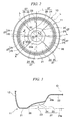
- FIG. 2 is a view for illustrating Embodiment 1 of the bottle of the present invention and shows a plan view when the bottom of the bottle given in FIG. 1 is viewed below.
- FIG. 3 is a view for illustrating Embodiment 1 of the bottle of the present invention and a cross sectional view of the bottle cut along the line X-X given in FIG. 2 .
- FIG. 4 is a view for illustrating Embodiment 1 of the bottle of the present invention and a cross sectional view of the bottle cut along the line Y-Y given in FIG. 2 .
- FIG. 5 is a view for illustrating Embodiment 2 of the bottle of the present invention and a plan view illustrating the bottom of the bottle.
- FIG. 6 is a view for illustrating an embodiment of the bottle of the present invention.
- the bottle 10 of the present embodiment is provided with a heel portion 12 , a body portion 13 , a shoulder portion 14 and a mouth portion 15 .
- the bottle 10 is made with a synthetic resin such as polyethylene terephthalate and produced by, for example, blow molding.
- the heel portion 12 is provided with a bottom 11 .
- the body portion 13 is installed to be continued to the upper edge portion of the heel portion 12 .
- the shoulder portion 14 is installed to be continued to the upper edge portion of the body portion 13 and gradually reduced in diameter along the upward direction.
- the mouth portion 15 is installed to be continued to the upper edge portion of the shoulder portion 14 and extended upwardly.
- the bottom 11 , heel portion 12 , body portion 13 , shoulder portion 14 and mouth portion 15 are formed in an integrated manner along a predetermined axial line.
- the axial line is given as a central axis line O.
- a cross section perpendicular to the central axis line O of the bottle 10 is substantially in a circular shape.
- a male thread portion 15 a is made at the mouth portion 15 , and a cap (not illustrated) is screwed on at the male thread portion 15 a.
- a plurality of panel portions 13 a are installed at the body portion 13 so as to be spaced at an equal interval along the circumferential direction of the body portion 13 .
- Each of the panel portions 13 a is formed so as to be recessed internally in a radial direction of the body portion 13 .
- a column portion 13 b extending toward the central axis line O is formed between the adjacent panel portions 13 a .
- the panel portion 13 a and the column portion 13 b are arranged alternately along the circumferential direction of the body portion 13 .
- the panel portion 13 a is formed along a full length excluding the upper edge portion 13 c and the lower edge portion 13 d in the direction of the central axis line O of the body portion 13 .
- the panel portion 13 a and the column portion 13 b are formed with six pieces each.
- An annular recess groove 16 is formed at a joint between the heel portion 12 and the body portion 13 all along the circumference in the circumferential direction of the body portion 13
- an annular recess groove 17 is formed at a joint between the body portion 13 and the shoulder portion 14 all along the circumference in the circumferential direction of the body portion 13 .
- the bottom 11 is provided with a base portion 21 , a central recess 22 , an annular wall portion 23 , and a plurality of ribs 27 .
- the base portion 21 is installed on the outer circumference brim of the bottom 11 , and touches the ground when the bottle 10 is set upright, with the mouth portion 15 kept above the base portion 21 .
- the central recess 22 is installed on the inside of the base portion 21 and recessed toward the inside of the bottle 10 .
- the annular wall portion 23 is installed between the base portion 21 and the central recess 22 and inclined so as to elevate gradually from the base portion 21 to the central recess 22 .
- a plurality of ribs 27 are installed side by side in the circumferential direction of the bottom 11 and protruding toward the inside of the bottle 10 .
- Each of the ribs 27 is provided with a rising wall portion 25 and an inclined wall portion 24 .
- the rising wall portion 25 rises steeply toward the inside of the bottle 10 .
- the inclined wall portion 24 rises gently toward the inside of the bottle 10 .
- the rising wall portion 25 is steeper than the inclined wall portion 24 . It is noted that the number of ribs 27 is preferably from 4 to 16.
- the inclined wall portion 24 is formed in a circular arc shape at which the length along the circumferential direction of the bottom 11 is made longer as it moves closer to the base portion 21 , in other words, a fan shape.
- the rising wall portion 25 is formed in a triangular shape so as to be tapered as it comes closer to the base portion 21 , when the bottom 11 is also viewed in the direction of the central axis line O outside of the bottle 10 .
- the inclined wall portions 24 are all formed in the same shape and the rising wall portions 25 are also all formed in the same shape.
- the inclined wall portion 24 and the rising wall portion 25 are alternately arranged in the circumferential direction of the bottom 11 . Further, the circumferential face 22 a of the central recess 22 is formed in a ratchet shape.
- the inclined wall portion 24 is inclined from the base portion 21 to the central recess 22 and also curved so as to be recessed toward the inside of the bottle 10 .
- the inclined wall portion 24 is formed in a flat-face shape and inclined from the lower brim of the rising wall portion 25 of an adjacent rib 27 toward the upper brim 25 a of the rising wall portion 25 to give the rib 27 in combination with itself.
- edge portion of the inclined wall portion 24 located inside the bottom 11 in a radial direction and the edge portion of the rising wall portion 25 located inside in the radial direction are made steeper along the central recess 22 , smoothly continuing to the circumferential face 22 a of the central recess 22 .
- the upper brim 25 a of the rising wall portion 26 is extended in a direction coincident with a radial direction of the bottom 11 of the bottle 10 .
- the upper brim 26 a of the rising wall portion 25 is extended in a direction coincident with a direction that a line L is extended which connects a point at which the rising wall portion 25 is in contact with the base portion 21 with the center of the bottle 10 (central axis line O).
- an angle ⁇ 1 made by the outer surface 25 b of the rising wall portion 25 and the outer surface 21 a of the base portion 21 is set to be in a range of 45 degrees to 90 degrees and preferably in a range of 60 degrees to 75 degrees.
- an angle ⁇ 2 made by the outer surface 24 a of the inclined wall portion 24 and the outer surface 21 a of the base portion 21 is set to be in a range of 5 degrees to 45 degrees and preferably in a range of 15 degrees to 30 degrees.
- a step portion 26 is formed inside the base portion 21 so as to be recessed toward the inside of the bottle 10 .
- the edge portion of the inclined wall portion 24 located outside the bottom 11 in the radial direction and the edge portion of the rising wall portion 25 located outside in the radial direction continue to the base portion 21 via the step portion 26 .
- the inner surface of the bottom 11 is formed along the outer surface of the bottom 11 , and the thickness of the bottom 11 is equal throughout.
- a plurality of ribs 27 provided with an inclined wall portion 24 and a rising wall portion 25 steeper than the inclined wall portion 24 are formed at the annular wall portion 23 . Therefore, an increased internal pressure of the bottle 10 will disperse a load acting on a joint between the ridge of each rib 27 , that is, an inclined wall portion 24 of each rib 27 and the rising wall portion 25 from the joint to the inclined wall portion 24 .
- the annular wall portion 23 is not complicated in configuration. Therefore, the inside of the bottle can be sufficiently cleaned before a liquid or the like is filled into the bottle 10 . Still further, since a cleaning liquid can easily flow along the inclined wall portion 24 , the cleaning liquid can be easily discharged from the bottle 10 to prevent a decrease in the handling property of the bottle 10 .
- each of the ribs 27 which is provided with the inclined wall portion 24 and the rising wall portion 25 , continues to the base portion 21 via the step portion 26 . Therefore, when the bottle 10 is produced by blow molding, a poor configuration of the bottle 10 can be prevented even when a mold is worn.
- the rib 27 is expanded in the circumferential direction of the bottle 10 and crushed more easily. Further, where the angle ⁇ 1 is larger than 90 degrees, the bottle 10 is inferior in molding property.
- Embodiment 2 of the present invention an explanation will be given for Embodiment 2 of the present invention. It is noted that the same parts as those of Embodiment 1 are given the same symbols and numerals and explanations thereof are omitted, with only different parts being explained here.
- a rising wall portion 31 constituting the rib 27 together with the inclined wall portion 24 is formed at the annular wall portion 23 .
- the upper brim 31 a of the rising wall portion 31 is extended in a direction which is inclined in a radial direction to the bottom 11 of the bottle 30 .
- the upper brim 31 a of the rising wall portion 31 is extended in a direction inclined to a line L which connects a point at which the rising wall portion 31 is in contact with the base portion 21 with the center (central axis line O) of the bottle 30 .
- the rising wall portion 31 of each rib 27 is extended so as to be spaced from the line L gradually in a counterclockwise direction as it moves from the base portion 21 to the central recess 22 .
- an angle ⁇ 3 made by a direction at which the upper brim 31 a of the rising wall portion 31 is extended and the line L is set to be, for example, 30 degrees or less and preferably 15 degrees or less.
- the angle ⁇ 3 may be changed, whenever necessary, depending on the number of the ribs 27 or the like. In the present embodiment, the angle ⁇ 3 is set to be approximately 8 degrees.
- the upper brim 31 a of the rising wall portion 31 is extended in a direction inclined to the line L. Therefore, even when a force is exerted which allows the inclined wall portion 24 to move outside the bottle 30 , with an edge portion opposite to the joint of the inclined wall portion 24 being used as a supporting point due to an increase in internal pressure of the bottle 30 , the inclined wall portion 24 is deformed so as to cover the rising wall portion 31 and the rising wall portion 31 stops the force, thereby preventing the rib 27 from being expanded in a circumferential direction and deformed so as to be crushed. Therefore, it is possible to further improve the compressive strength of the bottle 30 .
- the transverse cross section is substantially circular, for example. It is, however, acceptable that the bottle is such that, the transverse cross section of which is substantially rectangular.
- the step portion 26 is formed at the bottom 11 . It is also acceptable that the step portion 26 is not formed but the edge portion of the inclined wall portion 24 located outside the bottom 11 in a radial direction and the edge portion of the rising wall portion 25 (or 31 ) located in the radial direction are directly connected to the base portion 21 .
- a joint between the inclined wall portion 24 of each rib 27 and the rising wall portion 25 is formed so as to give a ridge, while a joint between the inclined wall portion 24 with an adjacent rib 27 and the rising wall portion 25 is formed so as to form a valley.
- a flat-face portion is formed between the inclined wall portion 24 and the rising wall portion 25 and the inclined wall portion 24 is connected with the rising wall portion 25 via the flat-face portion.
- the inclined wall portion 24 is inclined from the base portion 21 to the central recess 22 and also curved so as to be recessed to the inside of the bottle 10 .
- the inclined wall portion 24 may be curved so as to protrude outside the bottle 10 or inclined in a flat face shape.
- the inclined wall portion 24 is formed in a flat-face shape and inclined from the lower brim of the rising wall portion 25 of an adjacent rib 27 toward the upper brim 25 a of the rising wall portion 25 to give the rib 27 in combination with itself.
- the inclined wall portion 24 may be curved so as to be recessed to the inside of the bottle 10 or may be curved so as to protrude outside the bottle 10 .
- the inclined wall portion 24 and the rising wall portion 25 may be changed in position toward the circumferential direction of the bottle so that they can be exchanged with each other.
- Example 1 The bottle 10 of Embodiment 1 was adopted as Example 1, and the bottle 30 of Embodiment 2 was adopted as Example 2.
- Example 1 the bottle 10 of Embodiment 1 is adopted which is not provided with the inclined wall portion 24 or the rising wall portion 25 .
- Example 2 the bottle 30 of Embodiment 2 is adopted which is not provided with the inclined wall portion 24 or the rising wall portion 31 .
- each of the comparative examples was 0.147 MPa in compressive strength, whereas Example 1 was 0.333 MPa and Example 2 was 0.363 MPa. In other words, it was confirmed that Example 1 and Example 2 were improved in compressive strength two times or more than the comparative examples.
- the present invention relates to a bottle, which is provided with a base portion installed on the outer circumference brim of the bottom, a central recess installed inside the base portion and recessed toward the inside of the bottle, an annular wall portion installed between the base portion and the central recess and inclined so as to gradually elevate from the base portion to the central recess, and a plurality of ribs installed side by side at the annular wall portion in the circumferential direction of the bottom and protruding toward the inside of the bottle, in which the ribs are provided with a rising wall portion rising toward the inside of the bottle and an inclined wall portion inclined from the upper brim of the rising wall portion toward the lower brim of the rising wall portion of an adjacent rib, and the rising wall portion is inclined more steeply than the inclined wall portion.
Abstract
Description
- PATENT DOCUMENT 1: Japanese Unexamined Patent Application, First Publication No. 2002-308245
-
- 10, 30: BOTTLE
- 11: BOTTOM
- 21: BASE PORTION
- 22: CENTRAL RECESS
- 23: ANNULAR WALL PORTION
- 24: INCLINED WALL PORTION
- 25, 31: RISING WALL PORTION
- 27: RIB
- O: CENTRAL AXIS LINE
Claims (6)
Applications Claiming Priority (3)
| Application Number | Priority Date | Filing Date | Title |
|---|---|---|---|
| JP2005-241140 | 2005-08-23 | ||
| JP2005241140A JP4642601B2 (en) | 2005-08-23 | 2005-08-23 | Bottle |
| PCT/JP2006/314557 WO2007023630A1 (en) | 2005-08-23 | 2006-07-24 | Bottle |
Publications (2)
| Publication Number | Publication Date |
|---|---|
| US20090020497A1 US20090020497A1 (en) | 2009-01-22 |
| US9027770B2 true US9027770B2 (en) | 2015-05-12 |
Family
ID=37771381
Family Applications (1)
| Application Number | Title | Priority Date | Filing Date |
|---|---|---|---|
| US11/990,462 Expired - Fee Related US9027770B2 (en) | 2005-08-23 | 2006-07-24 | Bottle |
Country Status (9)
| Country | Link |
|---|---|
| US (1) | US9027770B2 (en) |
| EP (1) | EP1918213B1 (en) |
| JP (1) | JP4642601B2 (en) |
| KR (1) | KR101225539B1 (en) |
| CN (1) | CN100546880C (en) |
| AU (1) | AU2006282584B2 (en) |
| CA (1) | CA2619947C (en) |
| TW (1) | TWI301817B (en) |
| WO (1) | WO2007023630A1 (en) |
Cited By (2)
| Publication number | Priority date | Publication date | Assignee | Title |
|---|---|---|---|---|
| US20150041426A1 (en) * | 2012-02-29 | 2015-02-12 | Yoshino Kogyosho Co., Ltd. | Bottle |
| US20210039825A1 (en) * | 2018-04-26 | 2021-02-11 | Graham Packaging Company, L.P. | Pressurized refill container resistant to standing ring cracking |
Families Citing this family (19)
| Publication number | Priority date | Publication date | Assignee | Title |
|---|---|---|---|---|
| FR2961181B1 (en) * | 2010-06-11 | 2012-07-27 | Sidel Participations | CONTAINER COMPRISING A VOUTE BOTTOM IN SQUARE SQUARE |
| FR2961180B1 (en) * | 2010-06-11 | 2013-06-07 | Sidel Participations | CONTAINER COMPRISING A VOUTE RIB BOTTOM |
| CA2817555C (en) | 2010-11-12 | 2019-05-28 | Niagara Bottling, Llc | Preform extended finish for processing light weight bottles |
| US10647465B2 (en) | 2010-11-12 | 2020-05-12 | Niagara Bottling, Llc | Perform extended finish for processing light weight ecologically beneficial bottles |
| US10118724B2 (en) | 2010-11-12 | 2018-11-06 | Niagara Bottling, Llc | Preform extended finish for processing light weight ecologically beneficial bottles |
| US10829260B2 (en) | 2010-11-12 | 2020-11-10 | Niagara Bottling, Llc | Preform extended finish for processing light weight ecologically beneficial bottles |
| JP5953023B2 (en) * | 2011-09-29 | 2016-07-13 | 大和製罐株式会社 | Resin container and method for manufacturing resin container |
| EP3536623B1 (en) | 2011-12-05 | 2024-04-17 | Niagara Bottling, LLC | Plastic container with varying depth ribs |
| US11845581B2 (en) | 2011-12-05 | 2023-12-19 | Niagara Bottling, Llc | Swirl bell bottle with wavy ribs |
| US10023346B2 (en) | 2012-12-27 | 2018-07-17 | Niagara Bottling, Llc | Swirl bell bottle with wavy ribs |
| AU2013370421B2 (en) | 2012-12-27 | 2017-09-28 | Niagara Bottling, Llc | Plastic container with strapped base |
| USD699115S1 (en) | 2013-05-07 | 2014-02-11 | Niagara Bottling, Llc | Plastic container |
| USD696126S1 (en) | 2013-05-07 | 2013-12-24 | Niagara Bottling, Llc | Plastic container |
| USD699116S1 (en) | 2013-05-07 | 2014-02-11 | Niagara Bottling, Llc | Plastic container |
| US20170041743A1 (en) * | 2015-08-03 | 2017-02-09 | Punch Technologies, Inc. | Methods and Systems for Reporting and Providing Improved, Close-Proximity Assistance |
| USD858294S1 (en) | 2016-09-29 | 2019-09-03 | Ocean Spray Cranberries, Inc. | Bottle |
| JP7068910B2 (en) | 2018-04-24 | 2022-05-17 | 株式会社吉野工業所 | Bottle |
| US11597556B2 (en) | 2018-07-30 | 2023-03-07 | Niagara Bottling, Llc | Container preform with tamper evidence finish portion |
| USD1002384S1 (en) * | 2021-06-18 | 2023-10-24 | Pepsico, Inc. | Bottle |
Citations (16)
| Publication number | Priority date | Publication date | Assignee | Title |
|---|---|---|---|---|
| US3468443A (en) * | 1967-10-06 | 1969-09-23 | Apl Corp | Base of plastic container for storing fluids under pressure |
| JPS57174321U (en) | 1981-04-28 | 1982-11-04 | ||
| JPS5846713U (en) | 1981-09-22 | 1983-03-29 | 東洋製罐株式会社 | pressure resistant plastic bottle |
| US4497855A (en) * | 1980-02-20 | 1985-02-05 | Monsanto Company | Collapse resistant polyester container for hot fill applications |
| US4620639A (en) * | 1978-11-07 | 1986-11-04 | Yoshino Kogyosho Co., Ltd. | Synthetic resin thin-walled bottle |
| JPS6228335A (en) | 1985-07-16 | 1987-02-06 | 山村硝子株式会社 | Bottom structure of vessel made of plastic |
| US4840289A (en) * | 1988-04-29 | 1989-06-20 | Sonoco Products Company | Spin-bonded all plastic can and method of forming same |
| US4993566A (en) * | 1989-12-19 | 1991-02-19 | Hoover Universal, Inc. | Spiral container base structure for hot fill pet container |
| JPH04294735A (en) | 1991-03-22 | 1992-10-19 | Nissei Asb Mach Co Ltd | Bottom wall structure of synthetic resin container |
| US5503283A (en) * | 1994-11-14 | 1996-04-02 | Graham Packaging Corporation | Blow-molded container base structure |
| JPH08267549A (en) | 1995-03-28 | 1996-10-15 | Toyo Seikan Kaisha Ltd | Heat and pressure-resistant self-supporting container and production thereof |
| US5763030A (en) * | 1993-11-29 | 1998-06-09 | Nissei Asb Machine Co., Ltd. | Biaxially stretch blow-molded article and bottom mold therefor |
| US6041961A (en) * | 1998-05-14 | 2000-03-28 | F'real! Foods, Llc | Cup with anti-rotation mechanism |
| JP2002166916A (en) | 2000-11-29 | 2002-06-11 | Yoshino Kogyosho Co Ltd | Biaxial drawing blow-molded light-weighted bottle container made of synthetic resin and manufacturing method thereof |
| JP2002308245A (en) | 2001-04-10 | 2002-10-23 | Mitsubishi Plastics Ind Ltd | Plastic bottle |
| FR2856380A1 (en) | 2003-06-19 | 2004-12-24 | Sidel Sa | CONTAINER OF THERMOPLASTIC MATERIAL AND WITH CHAMPAGNE BACKGROUND |
Family Cites Families (2)
| Publication number | Priority date | Publication date | Assignee | Title |
|---|---|---|---|---|
| JPS5646713U (en) * | 1979-09-14 | 1981-04-25 | ||
| JP2005241140A (en) * | 2004-02-26 | 2005-09-08 | Sanyo Electric Co Ltd | Damper device |
-
2005
- 2005-08-23 JP JP2005241140A patent/JP4642601B2/en active Active
-
2006
- 2006-07-24 CN CNB2006800302984A patent/CN100546880C/en not_active Expired - Fee Related
- 2006-07-24 AU AU2006282584A patent/AU2006282584B2/en not_active Ceased
- 2006-07-24 WO PCT/JP2006/314557 patent/WO2007023630A1/en active Application Filing
- 2006-07-24 KR KR1020087005940A patent/KR101225539B1/en active IP Right Grant
- 2006-07-24 US US11/990,462 patent/US9027770B2/en not_active Expired - Fee Related
- 2006-07-24 EP EP06781479A patent/EP1918213B1/en not_active Expired - Fee Related
- 2006-07-24 CA CA2619947A patent/CA2619947C/en active Active
- 2006-08-21 TW TW095130691A patent/TWI301817B/en active
Patent Citations (19)
| Publication number | Priority date | Publication date | Assignee | Title |
|---|---|---|---|---|
| US3468443A (en) * | 1967-10-06 | 1969-09-23 | Apl Corp | Base of plastic container for storing fluids under pressure |
| US4620639A (en) * | 1978-11-07 | 1986-11-04 | Yoshino Kogyosho Co., Ltd. | Synthetic resin thin-walled bottle |
| US4497855A (en) * | 1980-02-20 | 1985-02-05 | Monsanto Company | Collapse resistant polyester container for hot fill applications |
| JPS57174321U (en) | 1981-04-28 | 1982-11-04 | ||
| JPS5846713U (en) | 1981-09-22 | 1983-03-29 | 東洋製罐株式会社 | pressure resistant plastic bottle |
| JPS6228335A (en) | 1985-07-16 | 1987-02-06 | 山村硝子株式会社 | Bottom structure of vessel made of plastic |
| US4840289A (en) * | 1988-04-29 | 1989-06-20 | Sonoco Products Company | Spin-bonded all plastic can and method of forming same |
| US4993566A (en) * | 1989-12-19 | 1991-02-19 | Hoover Universal, Inc. | Spiral container base structure for hot fill pet container |
| JPH04294735A (en) | 1991-03-22 | 1992-10-19 | Nissei Asb Mach Co Ltd | Bottom wall structure of synthetic resin container |
| US5763030A (en) * | 1993-11-29 | 1998-06-09 | Nissei Asb Machine Co., Ltd. | Biaxially stretch blow-molded article and bottom mold therefor |
| US5503283A (en) * | 1994-11-14 | 1996-04-02 | Graham Packaging Corporation | Blow-molded container base structure |
| JPH08267549A (en) | 1995-03-28 | 1996-10-15 | Toyo Seikan Kaisha Ltd | Heat and pressure-resistant self-supporting container and production thereof |
| US5906286A (en) | 1995-03-28 | 1999-05-25 | Toyo Seikan Kaisha, Ltd. | Heat-resistant pressure-resistant and self standing container and method of producing thereof |
| US6041961A (en) * | 1998-05-14 | 2000-03-28 | F'real! Foods, Llc | Cup with anti-rotation mechanism |
| JP2002166916A (en) | 2000-11-29 | 2002-06-11 | Yoshino Kogyosho Co Ltd | Biaxial drawing blow-molded light-weighted bottle container made of synthetic resin and manufacturing method thereof |
| US20040022976A1 (en) | 2000-11-29 | 2004-02-05 | Toyoji Kato | Biaxially stretch-blow molded lightweight synthetic resin bottle container and method for production thereof |
| JP2002308245A (en) | 2001-04-10 | 2002-10-23 | Mitsubishi Plastics Ind Ltd | Plastic bottle |
| FR2856380A1 (en) | 2003-06-19 | 2004-12-24 | Sidel Sa | CONTAINER OF THERMOPLASTIC MATERIAL AND WITH CHAMPAGNE BACKGROUND |
| US20070000858A1 (en) | 2003-06-19 | 2007-01-04 | Michel Boukobza | Container made from thermoplastic material with a domed base |
Non-Patent Citations (1)
| Title |
|---|
| Oct. 5, 2009 Search Report issued in EP 06 78 1479. |
Cited By (4)
| Publication number | Priority date | Publication date | Assignee | Title |
|---|---|---|---|---|
| US20150041426A1 (en) * | 2012-02-29 | 2015-02-12 | Yoshino Kogyosho Co., Ltd. | Bottle |
| US10017312B2 (en) * | 2012-02-29 | 2018-07-10 | Yoshino Kogyosho Co., Ltd. | Bottle |
| US10081476B2 (en) | 2012-02-29 | 2018-09-25 | Yoshino Kogyosho Co., Ltd. | Bottle |
| US20210039825A1 (en) * | 2018-04-26 | 2021-02-11 | Graham Packaging Company, L.P. | Pressurized refill container resistant to standing ring cracking |
Also Published As
| Publication number | Publication date |
|---|---|
| EP1918213B1 (en) | 2011-12-21 |
| KR101225539B1 (en) | 2013-01-23 |
| EP1918213A4 (en) | 2009-11-04 |
| JP4642601B2 (en) | 2011-03-02 |
| CN100546880C (en) | 2009-10-07 |
| CN101242995A (en) | 2008-08-13 |
| CA2619947A1 (en) | 2007-03-01 |
| WO2007023630A1 (en) | 2007-03-01 |
| TWI301817B (en) | 2008-10-11 |
| AU2006282584A1 (en) | 2007-03-01 |
| AU2006282584B2 (en) | 2011-09-29 |
| US20090020497A1 (en) | 2009-01-22 |
| EP1918213A1 (en) | 2008-05-07 |
| KR20080047552A (en) | 2008-05-29 |
| CA2619947C (en) | 2014-06-03 |
| JP2007055638A (en) | 2007-03-08 |
| TW200728150A (en) | 2007-08-01 |
Similar Documents
| Publication | Publication Date | Title |
|---|---|---|
| US9027770B2 (en) | Bottle | |
| US20240034507A1 (en) | Lightweight plastic container and preform | |
| US10214313B2 (en) | Bottle | |
| US7198165B2 (en) | Molded plastic hot-fill container and method of manufacture | |
| CN105905387B (en) | Container with the small-flowered shape bottom with transverse concave groove | |
| US9650207B2 (en) | Cylindrical bottle with bottom | |
| US7416088B2 (en) | Container made from thermoplastic material with a domed base | |
| US11634247B2 (en) | Bottle | |
| EP3638593B1 (en) | Container having a bottom base provided with notches | |
| TWI270506B (en) | Synthetic resin bottle container | |
| US8109397B2 (en) | Plastic container with curved base section | |
| CN103492274A (en) | Bottle | |
| US7083059B1 (en) | Thermoplastic container with petaloid base | |
| AU2011272394B2 (en) | Synthetic resin container | |
| JP6647759B2 (en) | Blow molded bottle made of synthetic resin | |
| US11130608B2 (en) | Square bottle | |
| JP2013154908A (en) | Bottle | |
| JP6335736B2 (en) | Bottle | |
| JP2023147379A (en) | Synthetic resin round bottle |
Legal Events
| Date | Code | Title | Description |
|---|---|---|---|
| AS | Assignment |
Owner name: YOSHINO KOGYOSYO CO., LTD., JAPAN Free format text: ASSIGNMENT OF ASSIGNORS INTEREST;ASSIGNORS:TANAKA, TOSHIMASA;IMAI, HIROAKI;IIZUKA, TAKAO;REEL/FRAME:020565/0691 Effective date: 20080212 |
|
| AS | Assignment |
Owner name: YOSHINO KOGYOSHO CO., LTD., JAPAN Free format text: ASSIGNMENT OF ASSIGNORS INTEREST;ASSIGNORS:TANAKA, TOSHIMASA;IMAI, HIROAKI;IIZUKA, TAKAO;REEL/FRAME:021786/0474 Effective date: 20081016 |
|
| STCF | Information on status: patent grant |
Free format text: PATENTED CASE |
|
| FEPP | Fee payment procedure |
Free format text: PAYOR NUMBER ASSIGNED (ORIGINAL EVENT CODE: ASPN); ENTITY STATUS OF PATENT OWNER: LARGE ENTITY |
|
| MAFP | Maintenance fee payment |
Free format text: PAYMENT OF MAINTENANCE FEE, 4TH YEAR, LARGE ENTITY (ORIGINAL EVENT CODE: M1551); ENTITY STATUS OF PATENT OWNER: LARGE ENTITY Year of fee payment: 4 |
|
| FEPP | Fee payment procedure |
Free format text: MAINTENANCE FEE REMINDER MAILED (ORIGINAL EVENT CODE: REM.); ENTITY STATUS OF PATENT OWNER: LARGE ENTITY |
|
| LAPS | Lapse for failure to pay maintenance fees |
Free format text: PATENT EXPIRED FOR FAILURE TO PAY MAINTENANCE FEES (ORIGINAL EVENT CODE: EXP.); ENTITY STATUS OF PATENT OWNER: LARGE ENTITY |
|
| STCH | Information on status: patent discontinuation |
Free format text: PATENT EXPIRED DUE TO NONPAYMENT OF MAINTENANCE FEES UNDER 37 CFR 1.362 |
|
| FP | Lapsed due to failure to pay maintenance fee |
Effective date: 20230512 |