US9031797B2 - Multiphase flow measurement - Google Patents
Multiphase flow measurement Download PDFInfo
- Publication number
- US9031797B2 US9031797B2 US12/672,531 US67253108A US9031797B2 US 9031797 B2 US9031797 B2 US 9031797B2 US 67253108 A US67253108 A US 67253108A US 9031797 B2 US9031797 B2 US 9031797B2
- Authority
- US
- United States
- Prior art keywords
- pipe
- liquid
- gas
- flow
- ultrasonic
- Prior art date
- Legal status (The legal status is an assumption and is not a legal conclusion. Google has not performed a legal analysis and makes no representation as to the accuracy of the status listed.)
- Active, expires
Links
Images


Classifications
-
- G—PHYSICS
- G01—MEASURING; TESTING
- G01F—MEASURING VOLUME, VOLUME FLOW, MASS FLOW OR LIQUID LEVEL; METERING BY VOLUME
- G01F1/00—Measuring the volume flow or mass flow of fluid or fluent solid material wherein the fluid passes through a meter in a continuous flow
- G01F1/74—Devices for measuring flow of a fluid or flow of a fluent solid material in suspension in another fluid
-
- G—PHYSICS
- G01—MEASURING; TESTING
- G01F—MEASURING VOLUME, VOLUME FLOW, MASS FLOW OR LIQUID LEVEL; METERING BY VOLUME
- G01F1/00—Measuring the volume flow or mass flow of fluid or fluent solid material wherein the fluid passes through a meter in a continuous flow
- G01F1/66—Measuring the volume flow or mass flow of fluid or fluent solid material wherein the fluid passes through a meter in a continuous flow by measuring frequency, phase shift or propagation time of electromagnetic or other waves, e.g. using ultrasonic flowmeters
- G01F1/663—Measuring the volume flow or mass flow of fluid or fluent solid material wherein the fluid passes through a meter in a continuous flow by measuring frequency, phase shift or propagation time of electromagnetic or other waves, e.g. using ultrasonic flowmeters by measuring Doppler frequency shift
-
- G—PHYSICS
- G01—MEASURING; TESTING
- G01F—MEASURING VOLUME, VOLUME FLOW, MASS FLOW OR LIQUID LEVEL; METERING BY VOLUME
- G01F1/00—Measuring the volume flow or mass flow of fluid or fluent solid material wherein the fluid passes through a meter in a continuous flow
- G01F1/66—Measuring the volume flow or mass flow of fluid or fluent solid material wherein the fluid passes through a meter in a continuous flow by measuring frequency, phase shift or propagation time of electromagnetic or other waves, e.g. using ultrasonic flowmeters
- G01F1/667—Arrangements of transducers for ultrasonic flowmeters; Circuits for operating ultrasonic flowmeters
-
- G—PHYSICS
- G01—MEASURING; TESTING
- G01F—MEASURING VOLUME, VOLUME FLOW, MASS FLOW OR LIQUID LEVEL; METERING BY VOLUME
- G01F1/00—Measuring the volume flow or mass flow of fluid or fluent solid material wherein the fluid passes through a meter in a continuous flow
- G01F1/704—Measuring the volume flow or mass flow of fluid or fluent solid material wherein the fluid passes through a meter in a continuous flow using marked regions or existing inhomogeneities within the fluid stream, e.g. statistically occurring variations in a fluid parameter
- G01F1/708—Measuring the time taken to traverse a fixed distance
- G01F1/7082—Measuring the time taken to traverse a fixed distance using acoustic detecting arrangements
-
- G—PHYSICS
- G01—MEASURING; TESTING
- G01F—MEASURING VOLUME, VOLUME FLOW, MASS FLOW OR LIQUID LEVEL; METERING BY VOLUME
- G01F3/00—Measuring the volume flow of fluids or fluent solid material wherein the fluid passes through the meter in successive and more or less isolated quantities, the meter being driven by the flow
- G01F3/30—Wet gas-meters
Definitions
- This disclosure relates in general to multiphase flow measurement for oil-gas wells and, but not by way of limitation, to high gas volume flow fraction/holdup and/or velocity/flow-rate measurements.
- GVF gas volume fraction
- WLR water/liquid hydrocarbon ratio
- the separation approach provides for splitting the flow into an almost liquid flow in one channel/conduit and an almost gas flow in a separate channel/conduit and then separately metering the separated flows using single-phase flow meters.
- the mixing approach attempts to minimize the slip between the different phases by mixing the phases into a homogeneous mixture so that the velocity and holdup measurements can be simplified.
- the existing methods are largely capable of providing good accuracy for metering gas flows with high GVF, however, the liquid rate metering accuracy is relatively poor.
- the disadvantage of such methods also include increased cost associated with the separation and mixing devices and extra pressure drop in the pipeline and/or disruption to the flow in the pipeline resulting from the introduction of the separation and/or mixing devices into the pipeline. Additionally, at high GVF, the mixing method may not provide for accurately measuring the holdup and WLR because the liquid holdup is very low under such conditions.
- Embodiments of the present invention provide for measuring flow properties of multiphase mixtures within a pipe carrying hydrocarbons produced from oil-gas wells.
- Embodiments of the present invention may provide for a combination of a clamp-on ultrasonic gas flow meter to measure flow characteristics of a gas phase in a pipeline and a pulsed Doppler sensor(s) and/or a radio-frequency (RF)/microwave electromagnetic (EM) sensor(s) to measure flow characteristics of a liquid phase.
- the combination of sensors may provide for multiphase flow measurements under certain flow conditions, such as for example when the gas-liquid is flowing in a substantially horizontal pipeline, when the flow is stratified or is caused to be stratified and/or the like. Stratification of the flow may be caused naturally by gravity separation or artificially by slowing down the flow through the use of pipe diameter expansion or contraction and/or the like.
- the present disclosure provides a method for measuring flow properties of a multiphase mixture of gas-liquid hydrocarbons and water flowing in a pipe of stratified flow.
- flow properties of a gas phase are measured in the pipe.
- Flow properties of a liquid phase are measured in the pipeline using a pulsed Doppler probe.
- a gas or liquid holdup is determined.
- a gas flow rate within the pipe is calculated using the gas holdup and the flow properties of the gas phase.
- a liquid flow rate within the pipe is calculated using the liquid holdup and the flow properties of the liquid phase.
- the present disclosure provides system for measuring flow properties of a multiphase mixture of gas-liquid hydrocarbons and water flowing in a pipe of stratified flow.
- the system includes an ultrasonic gas flow meter, a pulsed ultrasonic Doppler probe and a processor.
- the ultrasonic gas flow meter is configured to operatively engage the pipe and configured to measure flow properties of a gas phase in the pipe.
- the pulsed Doppler probe is configured to operatively engage with the pipe and configured to measure flow properties of a liquid phase in the pipe.
- the processor configured to determine a gas or liquid holdup, calculate gas flow rate within the pipe using the gas holdup and the flow properties of the gas phase, and calculate liquid flow rate within the pipe using the liquid holdup and the flow properties of the liquid phase.
- FIGS. 1A-1E depict block diagrams of embodiments of a multiphase flow measurement system
- FIGS. 2A-2E depict orthographic diagrams of embodiments of a pipe configuration detailing components of the multiphase flow measurement system
- FIGS. 3A-3E depict cross-sectional plan views of embodiments of the pipe configuration where the cross-section is in a plane generally parallel to a gas-liquid interface;
- FIGS. 4A-4E depict cross-sectional plan views of embodiments of the pipe configuration where the cross-section is in a plane generally perpendicular to flow within a pipeline;
- FIG. 5 depicts a block diagram of an embodiment of an ultrasonic pulsed Doppler probe engaged with a pipeline with multiphase flow
- FIG. 6 depicts a block diagram of an embodiment of an ultrasonic pulsed Doppler probe with beam focusing capabilities
- FIG. 7 illustrates a flowchart of an embodiment of a process for measuring multiphase flow of hydrocarbons within a pipeline.
- the transit-time ultrasonic transducers may be positioned close to or above a center line of the pipeline or at a location on the pipeline corresponding to where the gas phase may be flowing in the pipeline to measure the gas phase in the pipeline.
- An ultrasonic pulsed Doppler probe(s) and/or electromagnetic (EM) transmitter and receivers may be disposed around a bottom section of a pipeline or at locations where stratified flow may cause the liquid phase to flow in the pipeline.
- the EM transmitter and receivers are RF/microwave-based to determine water-to-liquid ratio (WLR) and water salinity (as described in U.S. Pat. No. 6,831,470, the entire disclosure of which is hereby incorporated by reference for all purposes).
- the ultrasonic pulsed Doppler probes are arranged in a Doppler array around the circumference of the pipeline to measure the gas-liquid flow. Additionally, the Doppler array can be used to estimate the WLR measurement in some embodiments. Other embodiments use EM transmission as a WLR meter.
- the flow regime in the horizontal flow is a stratified one if the liquid superficial velocity is less than 0.1 m/s and the gas superficial velocity is less than 25 m/s.
- the flow regime may take on an annular-mist flow. Applicants have found that even in the annular flows, however, most of the liquid forms a stratified layer towards the bottom part of the pipe bore while the rest of the liquid in the flow either forms a thin and slow-moving liquid film on the pipe wall, or is carried as droplets in the gas phase.
- liquid holdup is typically 15 times of liquid cut for GVF>0.95 and the liquid flow rate ⁇ 3 m 3 /hr. This means that if the liquid flow rate is 1% of the total flow rate, then the liquid holdup is 15%. Therefore, the gravity separation helps to create a liquid-rich region towards the lower part of a horizontal pipe, and a gas-rich region above it. Knowing the phase distribution in such flows, embodiments of the present invention provide various velocity and holdup measurements that may be optimized for the different phase regions. For instance, in certain aspects that liquid holdup measurement may be performed around the lower part of a horizontal pipe bore, whereas gas velocity may be measured at around the middle and upper part of the horizontal pipe. As such, one of the embodiments of the present invention provides for a multiphase flow meter that may, in certain aspects, be used to measure horizontal gas-liquid stratified flows, including high-gas and low-liquid wet-gas stratified flows.
- Embodiments of the present invention provide for metering of gas/water/oil flows from oil-gas producing wells.
- the GVF of the flow may be larger than 95% and the liquid flow rate may be less than 5 m 3 /hr.
- the flow regime for such flows in a horizontal pipeline is mainly stratified or slightly annular, i.e., most of the liquid phase forms a stratified flow layer towards the bottom of the pipe, whereas gas travels above the liquid phase. Utilizing such a natural separation of the phases, some embodiments of the present invention may provide for measuring the flow rates of the phases in the separate liquid and gas zones.
- embodiments of the present invention provide for a multi-sensor configuration for multiphase flow metering, which in some aspects may be optimized for metering horizontal stratified multiphase flows, including wet-gas flows under high-gas and low-liquid conditions.
- Gas velocity may be measured by using a gas flowmeter, e.g. an ultrasonic transit-time gas flowmeter, which may be installed around the appropriate height of the pipe bore to ensure measurement of the gas-only/gas-rich zone.
- An additional cross-pipe ultrasonic transmission measurement, along a direction that is perpendicular to the flow direction, may provide information on the liquid droplet holdup in the gas phase. Such information may be used to improve the accuracy of both gas and liquid flow rate measurements.
- the liquid flow velocity and liquid holdup may be measured by an array of ultrasonic Doppler sensors mounted around the circumference of the pipe.
- the WLR in the liquid-phase may be measured by at least one pair of EM wave transmitter and receiver, whose transmission path is mostly covered by the liquid-rich region towards the bottom of the pipe.
- the flowmeter may be built around a section of straight pipeline and may use non-intrusive sensors, and, therefore, provide no disturbance to the flow.
- an ultrasonic clamp-on transit-time gas flowmeter and a range-gated ultrasonic Doppler probe may be used for the measurement of gas and liquid flow velocities of stratified gas-liquid flow in a horizontal or near horizontal production pipeline.
- a pair of transit-time ultrasonic gas flow transducers may be installed to provide ultrasonic beam(s) across the pipe horizontally sideways.
- the ultrasonic Doppler probe may be installed at the pipe underside to measure the flow velocity and thickness (hence volume fraction or holdup) of the dominant liquid layer.
- the liquid-layer thickness may be estimated from a time delay measurement where the range-gated Doppler energy is at a maximum.
- the gas and liquid flow rates may then be determined from the above gas-liquid velocities and liquid fraction measurements, without intruding into the production flows within the pipeline.
- transit-time (gas) and Doppler (liquid) flow velocity and holdup measurements may also be used to derive the prevalent flow-regime information (from flow-regime maps), hence facilitating the use of a more flow-regime specific correlation of gas-liquid velocity slip for an alternative determination of gas-liquid flow rates.
- FIG. 1A a block diagram of an embodiment of a multiphase flow measurement system 100 - 1 is shown.
- the multiphase flow measurement system 100 measures stratified gas-liquid flow.
- this embodiment is variously described in at least FIGS. 1A , 2 A, 3 A, and 4 A.
- This embodiment includes an ultrasonic gas flowmeter 118 , an ultrasonic pulsed Doppler probe 120 , a processor 110 , and an interface port 114 .
- This embodiment is configured to operate where the GVF is below 75% or 80% and/or the flow rate corresponds to a low producing well such that the phases stratify in a horizontal pipeline (e.g., below about 2000-5000 bbl/day in a 3 inch pipeline).
- the ultrasonic gas flowmeter 118 measures a velocity of the gas phase. At least two transit-time ultrasonic transducers 116 send an ultrasonic signal between each other and the upstream and downstream flow transit times can be measured. The flow velocity of the gas phase affects the transit time, such that a measurement of the transit times can be used to derive the gas flow velocity.
- the transit-time ultrasonic transducers 116 can be configured to clamp-onto the pipeline or could be embedded into an orifice of the pipe wall. The pair of transit-time ultrasonic transducers 116 are clamped around the periphery of a horizontal production flow pipe to align the ultrasonic beam(s) across the pipe diameter horizontally sideways.
- the transit-time ultrasonic transducers 116 are positioned at different points along the pipeline such that they are angled with the flow direction of the gas phase. Each of the transit-time ultrasonic transducers 116 can both send and receive signals. Transit-time testing could involve one transit-time ultrasonic transducer 116 - 1 sending a first signal that is received by the other transit-time ultrasonic transducer 116 - 2 before a second signal is sent in the opposite direction.
- the ultrasonic pulsed Doppler probe 120 is range-gated in this embodiment.
- the Doppler probe 120 could operate at 1 MHz, for example, to measure flow velocity of the dominant liquid layer.
- This embodiment clamps the ultrasonic pulsed Doppler probe 120 on the pipe underside to measure the flow velocity of the dominant liquid layer flowing at the pipe bottom.
- the liquid level or height of the liquid-gas interface can also be determined by the ultrasonic pulsed Doppler probe 120 .
- the internal cross-sectional area of the pipe can be measured from an ultrasonic pipe-wall thickness gauge, or estimated with readings from the ultrasonic pulsed Doppler probe 120 .
- the internal cross-sectional area is used with the flow velocity and holdup measurements to determine the volume of liquid, hydrocarbon and/or gas passing through the pipeline per unit time.
- a processor 110 is configured with a state machine and/or software to automatically determine certain parameters from the gathered information. Additionally, the various probes and transducers are driven and read with the processor 110 . Gas, liquid and hydrocarbon flow velocity and volume fraction/holdup can be determined by the processor 110 . Any input or output of the multiphase flow measurement system 100 passes through an interface port 114 . Some embodiments could include a display that shows the determined results and measurements, but this embodiment just relays that information out the interface port 114 to a data logging device.
- FIG. 1B a block diagram of another embodiment of the multiphase flow measurement system 100 - 2 is shown.
- this embodiment is variously described in at least FIGS. 1B , 2 B, 3 B, and 4 B.
- This embodiment uses multiple ultrasonic pulsed Doppler probes 120 arranged into a Doppler array 122 to allow more accurate readings than when a single probe 120 is used.
- the spatial distribution of the probes 120 in the Doppler array 122 in some aspects of the present invention may be dense around the lower part of the horizontal pipe to provide better liquid-gas interface detection resolution.
- FIG. 1C a block diagram of yet another embodiment of the multiphase flow measurement system 100 - 3 is shown.
- this embodiment is variously described in at least FIGS. 1C , 2 C, 3 C, and 4 C.
- this embodiment also includes a gas wetness meter 108 that measures the wetness of the gas phase using ultrasonic gas wetness transducers 106 positioned on opposites of the pipeline near the top portion of the pipeline to be adjacent to the gas phase.
- the ultrasonic gas wetness transducers can be impedance matched to the gas expected in the pipeline.
- the gas wetness meter 108 measures wet-gas flow, in accordance with one embodiment of the present invention to correct for gas mist in the gas flow rate determination.
- gas velocity may be measured by an ultrasonic transit time method using the ultrasonic gas flowmeter 118 . For the configuration shown in FIGS.
- t AB is the ultrasonic transit time from point A to B (down stream)
- t BA is the upstream transit time
- X is the separation of the transducers along the flow direction
- L is the length of the ultrasonic propagation path
- V is the flow velocity. Note that in equation (1) the two transit time measurements are combined in such a way that the velocity of sound has no influence on the measurement of V.
- calculations of transit-times may be used to determine the mixture sound velocity c (note that c>>V), c ⁇ 2 L /( t AB +t BA ) (1B) This measured c may be combined with the measurement of the upstream/downstream transmission attenuation to derive gas-phase wetness.
- the ultrasound path is entirely through the gas phase.
- the liquid holdup is normally well below 50%, the ultrasound path can be in the horizontal plane intersecting the centre of the pipe.
- the droplet concentration may be measured by an ultrasonic energy propagating perpendicular to the flow direction. The transit time and attenuation of this energy can be used to estimate the holdup of the liquid mist.
- the attenuation of the ultrasonic energy is a linear function of droplet concentration provided that the concentration is low (typically less than 5% of pipe cross-section) and that the ultrasonic wavelength is chosen to be long compared with the droplet size.
- FIG. 1D a block diagram of still another embodiment of a multiphase flow measurement system 100 - 4 is shown.
- This embodiment includes an ultrasonic gas flowmeter 118 to measure gas velocity, a Doppler array 122 to measure liquid holdup and velocity of the liquid phase and a WLR meter 130 .
- This embodiment of the WLR meter 130 uses an electromagnetic (EM) wave transmitter 128 that sends a signal to a number of EM wave receivers 128 .
- EM electromagnetic
- the EM wave transmitter 128 is typically at the bottom of the pipeline, and the EM wave receivers 124 are placed around the circumference of the pipeline in places likely to be adjacent to the fluid layer.
- the WLR and water conductivity/salinity affects the transmitted EM wave phase-shift and/or amplitude-attenuation measurements such that WLR and water salinity can be determined.
- EM wave transmitters 128 could use multiple EM wave transmitters 128 working with a single EM wave receiver 124 .
- the EM wave transmitters 128 could transmit sequentially or at different frequencies simultaneously to achieve diversity in this embodiment.
- Prior embodiments estimated WLR using one or more ultrasonic pulsed Doppler probes 120 .
- This embodiment uses microwave EM devices 124 , 128 to determine WLR, although nuclear methods based on dual-energy Gamma-ray measurements may be used to replace the ultrasonic and microwave EM holdup measurements of other embodiments. Still other embodiments could use any combination of microwave EM, Gamma-ray and/or ultrasonic to determine WLR.
- FIG. 1E a block diagram of an embodiment of the multiphase flow measurement system 100 - 5 is shown.
- this embodiment is variously described in at least FIGS. 1E , 2 E, 3 E, and 4 E.
- This embodiment uses ultrasonic film measurement probes or transducers 132 near the gas phase to measure liquid or other film on the interior of the pipeline.
- the ultrasonic film measurement probes 132 are high frequency.
- the Doppler array 122 spaces its ultrasonic probes 120 more tightly around the lower part of the horizontal pipe to provide better liquid-gas interface detection resolution, whereas the film measurement probes 132 are sparse around the upper half for film thickness measurement.
- FIG. 2A an orthographic diagram of an embodiment of a pipe configuration 200 - 1 is shown that details components of the multiphase flow measurement system 100 - 1 .
- the pipeline 204 is made from a plastic liner 208 arranged in a cylindrical form. Within the pipeline are a liquid phase 240 and a gas phase 250 separated by a liquid-gas interface 230 . To show blocks on the obscured back side of the pipeline 204 , dashed lines are used for those blocks. For example, the first transmit-time ultrasonic transducer 116 - 1 is on the back side of the pipeline and the second transmit-time ultrasonic transducer 116 - 2 is on the front side.
- the transmit-time ultrasonic transducers 116 are placed at different places along the length of the pipeline 204 such that the signals are angled toward the axis of flow within the pipeline 204 .
- This embodiment uses a single ultrasonic pulsed Doppler probe 120 located at a bottom of the pipeline 204 .
- FIG. 2B an orthographic diagram of another embodiment of a pipe configuration 200 - 2 is shown that details components of the multiphase flow measurement system 100 - 2 .
- This embodiment has multiple ultrasonic pulsed Doppler probes 120 arranged circumferentially on a front of the pipeline 204 . Additional ultrasonic pulsed Doppler probes 120 allow for more accurate readings. Further, the height of the liquid-gas interface can be determined with generally better accuracy when there is a Doppler array 122 arranged about a circumference of the pipeline 204 .
- FIG. 2C an orthographic diagram of yet another embodiment of a pipe configuration 200 - 3 is shown that details components of the multiphase flow measurement system 100 - 3 .
- This embodiment is similar to the embodiment of FIG. 2B , but also includes the gas wetness meter 108 .
- Two ultrasonic gas wetness transducers 106 are arranged in the top hemisphere of the pipeline 204 in a position likely to be in contact with the gas layer 250 to form the gas wetness meter 108 .
- the two wetness transducers 106 are generally directly opposite each other along the same circumference.
- FIG. 2D an orthographic diagram of still another embodiment of a pipe configuration 200 - 4 is shown that details components of the multiphase flow measurement system 100 - 4 .
- This embodiment uses RF/microwave EM signals in a WLR (and water salinity) meter 130 .
- WLR and water salinity
- EM wave receivers 124 that receive an RF/microwave signal from the EM wave transmitter 128 positioned at the bottom of the pipeline.
- the various EM wave elements 124 , 128 are generally located along a same circumference of the pipeline 204 .
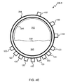
- an orthographic diagram of an embodiment of a pipe configuration 200 - 5 is shown that details components of the multiphase flow measurement system 100 - 5 .
- this embodiment has a Doppler array 122 and ultrasonic film, measurement transducers 132 .
- the Doppler array 122 may include seven ultrasonic pulsed Doppler probes 120 , as depicted in FIG. 2E , distributed along a circumference of the lower hemisphere of the pipeline 204 . In other embodiments, other amounts of Doppler probes may be used.
- the ultrasonic film measurement transducers 132 are distributed along a circumference of the upper hemisphere of the pipeline 204 .
- Other embodiments could distribute the probes 120 and transducers 132 somewhat randomly in their respective hemispheres and not necessarily along a same circumference with the others.
- FIG. 3A a cross-sectional plan view of an embodiment of the pipe configuration 200 - 1 is shown where the cross-section is in a plane generally parallel to the gas-liquid interface 230 around the middle or in the upper hemisphere of the pipeline 204 .
- the transit-time ultrasonic transducers 116 point toward each other and are embedded into the plastic liner 208 in this embodiment, but could be clamp on in other embodiments.
- the other elements of the multiphase flow measurement system 100 - 1 do not appear in this cross-section and are not depicted.
- FIG. 3B a cross-sectional plan view of another embodiment of the pipe configuration 200 - 2 is shown where the cross-section is in the plane generally parallel to the gas-liquid interface 230 .
- this embodiment shows one of the ultrasonic pulsed Doppler probes 120 that is part of a Doppler array 122 .
- FIG. 3C a cross-sectional plan view of yet another embodiment of the pipe configuration 200 - 3 is shown where the cross-section is in the plane generally parallel to the gas-liquid interface 230 .
- this embodiment shows ultrasonic gas wetness transducers 106 arranged in the plastic liner 208 , but other embodiments could use a clamp-on configuration.
- FIG. 3D a cross-sectional plan view of still another embodiment of the pipe configuration 200 - 4 is shown where the cross-section is in the plane generally parallel to the gas-liquid interface 230 .
- FIGS. 3D and 4D show the arrangement of the WLR meter 103 and its EM wave receiving/transmitting elements 124 , 128 . Only a single EM wave receiver 124 is shown in the cross-section of FIG. 3D , but it is to be understood that there are many EM wave receivers 124 distributed in a manner such that they are likely to be adjacent to the liquid phase 240 .
- an EM wave transmitter 128 and multiple EM wave receivers 124 are used for measuring water holdup and water salinity in the stratified liquid layer using RF/microwave methods, in accordance with one embodiment of the present invention.
- an EM wave transmitter 128 is mounted at the underside of the pipe (with a suitable dielectric-material window), emitting a frequency in the range of a few hundred MHz to a few GHz, for example.
- Several EM wave receivers 124 are mounted around the pipe circumference (also with suitable dielectric-material windows) at angular positions, for example, 30, 60 and 90 degrees from the EM wave transmitter 128 .
- An appropriate EM wave receiver 124 is selected according to its position with respect to the position of the gas-liquid interface 230 . Normally the EM wave receiver 124 whose position is above the gas-liquid interface 230 and who has the maximum percentage of its sensing path covered by liquid may provide the most sensitive measurement (e.g., the fourth EM wave receiver 124 - 4 in FIG. 4D ). The selection of the suitable EM wave receiver 124 - 4 can be helped by the gas-liquid interface measurement information produced by the ultrasonic Doppler array 122 measurements.
- the RF/microwave measurement is sensitive to the fraction of its transmission path that is covered by water. It is much less sensitive to the difference between oil and gas. As such, RF/microwave attenuation and the like are proportional to water holdup for a fixed water conductivity (salinity). Water holdup measured by the RF/microwave may be combined with the total liquid holdup measured by the method using the ultrasonic pulsed Doppler probe(s) 120 to derive the WLR. In case there is a slip between the oil and water (as in a stratified ease), the slip value, either estimated from a slip model or directly measured by the method using the ultrasonic pulsed Doppler probe(s) 120 , may be used in determining the WLR.
- RF/microwave measurement also gives an on-line determination of the water conductivity and hence water salinity of the prevalent water phase under a multiphase flow condition, such as described in U.S. Pat. No. 6,831,470, which is hereby incorporated in its entirety for all purposes.
- the flow rate of gas is given by Equation (2) above, in which the gas velocity V is measured by ultrasonic transit-time method and the holdup by various ultrasonic (Doppler and/or cross-pipe transmission) methods.
- the accuracy quoted for dry gas velocity measurement is high (i.e., within a few percent for a commercial meter), in the multiphase case, especially when significant slip between gas and liquid droplets exist, the accuracy might deteriorate.
- the gas holdup measurement error is confined to, say ⁇ 5% (such relative accuracy may be achievable for gas holdup larger than 70%, as in typical wet-gas flows), then a gas flow rate error of ⁇ 10% can be achieved.
- the liquid flow rate is determined from a combination of velocity and holdup both measured by ultrasonic Doppler methods, such as described in British Patent GB2363455 B.
- the velocity measurement accuracy achievable may be ⁇ 10%.
- the relative holdup measurement error on the other hand, may be difficult to minimize especially at low liquid holdups. Therefore one would expect an increasing liquid rate error as the liquid flow rate decreases and the GVF increases. Transducer design for the inline application and advanced signal processing can reduce the level of error.
- the contribution to the WLR error may come from the water holdup measurement error, the liquid holdup measurement error and also from the difference between the water holdup and the WLR because of a slip between the water and oil phases.
- the slip in velocity is likely to happen if the oil is separated from water in a stratified distribution. In this case, ignoring such a slip will lead to inaccurate estimation of the WLR and hence inaccurate oil and water flow rates.
- the Doppler array 122 with multiple probes 120 may be used to measure the velocity of the separated oil and that of the separated water in a stratified distribution, and hence the slip.
- the processor 110 can automatically recognize when such a slip is likely and change the models to more accurately estimate the WLR.
- FIG. 3E a cross-sectional plan view of an embodiment of the pipe configuration 200 - 5 is shown where the cross-section is in the plane generally parallel to the gas-liquid interface 230 .
- This embodiment has Doppler array 122 that extends from the front to the back of the pipeline. Additionally, there is an ultrasonic film measurement transducer 132 shown that is one of several to measure the liquid film 245 in the gas phase 250 .
- FIG. 4A a cross-sectional plan view of an embodiment of the pipe configuration 200 - 1 is shown where the cross-section is in a plane generally perpendicular to flow within the pipe 204 . Only some of the multiphase flow measurement system 100 - 1 is shown in this view. Specifically, the ultrasonic pulsed Doppler probe 120 is shown at the bottom of the pipeline 204 to measure the flow of the liquid phase 240 and the height of the gas-liquid interface 230 .
- FIG. 4B a cross-sectional plan view of another embodiment of the pipe configuration 200 - 2 is shown where the cross-section is in a plane generally perpendicular to flow within the pipe 204 .
- This view shows the Doppler array 122 of the multiphase flow measurement system 100 - 2 .
- Five ultrasonic pulsed Doppler probes 120 are used in this embodiment.
- the fifth ultrasonic pulsed Doppler probe 120 - 5 is above the gas-liquid interface 230 and the fourth ultrasonic pulsed Doppler probe 120 - 4 is below.
- the processor can determine that the gas-liquid interface 230 is between the two. Further, other probes below the gas-liquid interface 230 can estimate the height using reflections from the pulses.
- FIG. 4C a cross-sectional plan view of still another embodiment of the pipe configuration 200 - 3 is shown where the cross-section is in a plane generally perpendicular to flow within the pipe 204 . Portions of the multiphase flow measurement system 100 - 3 are depicted in this view. Specifically, a Doppler array 122 along with the gas wetness meter 108 . The passing of ultrasonic signals back and forth between the ultrasonic gas wetness transducers 106 is shown with a dashed line.
- FIG. 4D a cross-sectional plan view of yet another embodiment of the pipe configuration 200 - 4 is shown where the cross-section is in a plane generally perpendicular to flow within the pipe 204 . Portions of the multiphase flow measurement system 100 - 4 are depicted in this view.
- the four EM wave receivers 124 are shown distributed at different angles around a circumference of the lower hemisphere of the pipeline 204 .
- the EM wave transmitter 128 is located at the bottom of the pipeline 204 .
- FIG. 4E a cross-sectional plan view of an embodiment of the pipe configuration 200 - 5 is shown where the cross-section is in a plane generally perpendicular to flow within the pipe 204 .
- This view shows the Doppler array 122 of the multiphase flow measurement system 100 - 5 along with the ultrasonic film measurement transducers 132 .
- the three ultrasonic film measurement transducers 132 each take a reading of the film. By knowing the location of the gas-liquid interface 230 and fluid dynamics models, the amount of liquid in the film can be estimated by the processor 110 .
- the three high frequency (hence high spatial and velocity resolutions) Doppler transducers 132 may be mounted on the upper part of the pipe 204 to measure the velocity and the thickness of the liquid film in an annular flow. Such information may then combined with the measurement of the liquid layer 240 near the lower part of the pipe 204 , and with the flow rate of the entrained liquid droplets derived by the gas velocity flowmeter 118 and the gas wetness meter 108 to produce the overall liquid flow rate.
- the measurement around the stratified liquid layer 240 can be done using a frequency lower than that used for film thickness measurement.
- the spatial resolution is proportional to the frequency f and the attenuation proportional to frequency f 2 .
- the maximum velocity measurement range is inversely proportional to f.
- a frequency of 1 to 3 MHz may be used in some embodiments depending upon the pipe size and for a slow moving thin film on the pipe wall, a frequency of 4 to 8 MHz may be used.
- a 5 MHz frequency has a 0.3 mm thickness resolution in water.
- FIG. 5 a block diagram of an embodiment of the ultrasonic pulsed Doppler probe 120 engaged with the pipe 204 with multiphase flow is shown.
- a plastic block 515 is used to increase the accuracy of the ultrasonic pulsed Doppler probe 120 .
- the plastic block 515 absorbs energy from a transducer crystal 504 and is impedance matched to the plastic liner 208 .
- the function of the plastic block 515 is to attenuate energy traveling in the plastic liner wall 208 , and thus producing a more predictable beam pattern in the flow.
- Other embodiments could use materials other than plastic for the block 515 .
- liquid velocity and holdup measurements may be made by a Doppler array 122 of range-gated ultrasonic Doppler transducers 120 , which may be mounted around outside a pipe liner so that they are non-invasive to the flow. In such a configuration, the pipe circumference may be scanned by the Doppler array 122 .
- the liquid holdup may be determined from the Doppler energy distribution around the circumference.
- the velocity of the liquid phase 240 may be measured from the Doppler frequency shift.
- FIG. 6 a block diagram of an embodiment of an ultrasonic pulsed Doppler probe is shown that has beam focusing capabilities.
- the steel pipe-wall widens the ultrasonic beam and thus causes the reduction of the spatial resolution of the scan.
- the steel pipe may be replaced by a plastic liner 208 in a section of the pipeline, which allows use of a focusing mechanism to improve the resolution.
- a focusing delay-line can be made with a first material 604 that has a higher sound velocity than that of the plastic liner.
- the second material 608 has the same sound velocity as the pipe liner 208 .
- the refracted beam in the liner 208 will have a smaller divergence angle.
- various focusing can take place in this embodiment.
- Other embodiment may use multi-element transducer arrays and phased electrical excitation to achieve focusing.
- FIG. 7 a flowchart of an embodiment of a process 700 for measuring multiphase flow of hydrocarbons within a pipe 204 is shown.
- the depicted portion of the process begins in block 704 where the liquid and gas phases 240 , 250 are stratified.
- a horizontal section of pipe 204 may be used to stratify the multiphase mixture flow.
- the length of the horizontal section may be determined to provide for the stratified flow and in other aspects a system, such as an expansion section having an internal diameter greater than the pipe or the like may be used to reduce the flow rate of the multiphase mixture and provide for producing stratified flow in the horizontal section of pipe 204 .
- the flowing multiphase mixture may be interrogated by ultrasonic sensors, microwave sensors, optical sensors and/or the like to determine whether the multiphase mixture is flowing in a stratified flow regime.
- Doppler interrogation may be used to determine if and/or where in the pipe a liquid-gas boundary exists.
- the ultrasonic gas flowmeter 118 can measure the velocity of the gas phase 250 .
- One or more of the transit-time ultrasonic transducers 116 may be submerged or otherwise fouled with liquid when operational in the field. If that is the case, the processor 110 notes the error condition and may take corrective action, but the gas phase 250 reading may not be able to be gathered.
- the ultrasonic pulsed Doppler probe(s) 120 can measure the flow velocity of the liquid phase 240 in block 708 . Additionally, the ultrasonic pulsed Doppler probe(s) 120 can measure the height of the gas-liquid interface 230 in block 712 using reflections and/or register which probes 120 in a Doppler array 122 appear to not be submerged in the liquid phase.
- block 716 allows determination of the WLR of the stratified liquid phase which is confirmed by measurements performed in the previous blocks.
- the liquid film 245 in the gas phase 250 is optionally measured using ultrasonic film measurement transducers 132 .
- the gas wetness is measured in block 724 to determine if the gas flow measurement is likely to be accurate or if other algorithms should be used by the processor 110 to determine or estimate the gas flow.
- the gas phase flow rate, the liquid phase flow rate and/or the liquid hydrocarbon flow rate are determined in block 728 may be determined by the processor 110 . That information may be relayed to other systems and/or displayed.
- the following information can also be provided by the ultrasonic transit-time and range-gated Doppler systems:
Abstract
Description
(t BA −t AB)/(t BA t AB)=2XV/L 2 (1)
where tAB is the ultrasonic transit time from point A to B (down stream), tBA is the upstream transit time, X is the separation of the transducers along the flow direction, L is the length of the ultrasonic propagation path and V is the flow velocity. Note that in equation (1) the two transit time measurements are combined in such a way that the velocity of sound has no influence on the measurement of V.
c≈2L/(t AB +t BA) (1B)
This measured c may be combined with the measurement of the upstream/downstream transmission attenuation to derive gas-phase wetness.
q GAS =V(1−αLiq)A (2)
where αLiq is the liquid holdup in the pipe and A is the pipe cross-sectional area.
c=1/√(ρβ) (3)
where ρ is the density of the fluid mixture, β the compressibility and c the velocity of sound in the mixture.
-
- The extremely low values of Doppler energy cross-pipe profile is indicative of a single-phase gas flow or a single-phase liquid flow (often with marked velocity readings; there is often always impurities/scatters in oilfield water or oil flows).
- In the case of single-phase gas flow, ultrasonic transit-time
gas flow meter 118 provides a velocity reading. - The sound-velocity measurement from the transit-
time gas meter 118 may also be exploited in some cases for liquid fraction indication (e.g., entrained liquid mist/droplet fraction in the carrying gas). - The instantaneous velocity or energy readings of the pulsed Doppler system at selected pipe depth(s) may be exploited to indicate flow fluctuations related to flow-regime information (e.g. slug length/frequency); and
- Two Doppler probes may be installed axially apart at pipe underside and/or top-side to derive e.g. the slug velocity (which is closely related to gas velocity for slug flows) by cross-correlating their instantaneously sampled Doppler flow velocity or energy data.
Claims (19)
Priority Applications (1)
| Application Number | Priority Date | Filing Date | Title |
|---|---|---|---|
| US12/672,531 US9031797B2 (en) | 2007-09-18 | 2008-09-17 | Multiphase flow measurement |
Applications Claiming Priority (3)
| Application Number | Priority Date | Filing Date | Title |
|---|---|---|---|
| US97336207P | 2007-09-18 | 2007-09-18 | |
| PCT/GB2008/003139 WO2009037435A2 (en) | 2007-09-18 | 2008-09-17 | Multiphase flow measurement |
| US12/672,531 US9031797B2 (en) | 2007-09-18 | 2008-09-17 | Multiphase flow measurement |
Publications (2)
| Publication Number | Publication Date |
|---|---|
| US20110098938A1 US20110098938A1 (en) | 2011-04-28 |
| US9031797B2 true US9031797B2 (en) | 2015-05-12 |
Family
ID=40468485
Family Applications (1)
| Application Number | Title | Priority Date | Filing Date |
|---|---|---|---|
| US12/672,531 Active 2031-02-20 US9031797B2 (en) | 2007-09-18 | 2008-09-17 | Multiphase flow measurement |
Country Status (4)
| Country | Link |
|---|---|
| US (1) | US9031797B2 (en) |
| EP (1) | EP2191243A2 (en) |
| CN (1) | CN101802562B (en) |
| WO (1) | WO2009037435A2 (en) |
Cited By (13)
| Publication number | Priority date | Publication date | Assignee | Title |
|---|---|---|---|---|
| US20140076547A1 (en) * | 2012-09-20 | 2014-03-20 | Weatherford/Lamb, Inc. | Multiphase flowmeter for subsea applications |
| US20150247749A1 (en) * | 2012-07-24 | 2015-09-03 | Lanzhou Haimo Technologies, Co. Ltd. | Wet Gas Flow Measuring Method and Apparatus |
| US20150276446A1 (en) * | 2014-04-01 | 2015-10-01 | Saudi Arabian Oil Company | Flow line mounting arrangement for flow system transducers |
| US20150308869A1 (en) * | 2014-04-01 | 2015-10-29 | Saudi Arabian Oil Company | Flow data acquisition and telemetry processing systems |
| US9424674B2 (en) | 2014-04-01 | 2016-08-23 | Saudi Arabian Oil Company | Tomographic imaging of multiphase flows |
| US9714854B2 (en) | 2014-04-01 | 2017-07-25 | Saudi Arabian Oil Company | Multiphase in situ flow sensing with ultrasonic tomography and vortex shedding |
| US20170343398A1 (en) * | 2015-04-16 | 2017-11-30 | Panasonic Intellectual Property Management Co., Ltd. | Flow rate measurement device |
| US10088347B2 (en) | 2014-04-01 | 2018-10-02 | Saudi Arabian Oil Company | Flow data acquisition and telemetry processing system |
| US10126155B1 (en) * | 2017-08-25 | 2018-11-13 | Saudi Arabian Oil Company | Multi-layer flow and level visualizer |
| US10996091B2 (en) | 2015-07-23 | 2021-05-04 | Khalifa University of Science and Technology | System and method for real-time flow measurement in pipelines using THz imaging |
| US11745121B2 (en) | 2019-09-05 | 2023-09-05 | Khalifa University of Science and Technology | Inline demulsification device |
| US11788983B2 (en) | 2018-08-21 | 2023-10-17 | Schlumberger Technology Corporation | System having non-intrusive fluid sensor |
| US11841255B2 (en) | 2018-07-20 | 2023-12-12 | Schlumberger Technology Corporation | Systems, methods, and apparatus to measure multiphase flows |
Families Citing this family (34)
| Publication number | Priority date | Publication date | Assignee | Title |
|---|---|---|---|---|
| GB2447490B (en) | 2007-03-15 | 2009-05-27 | Schlumberger Holdings | Method and apparatus for investigating a gas-liquid mixture |
| WO2008130633A1 (en) * | 2007-04-18 | 2008-10-30 | Valerio Thomas A | Method and system for sorting and processing recycled materals |
| US20110112773A1 (en) * | 2007-09-18 | 2011-05-12 | Schlumberger Technology Corporation | Measuring properties of stratified or annular liquid flows in a gas-liquid mixture using differential pressure |
| GB2454256B (en) | 2007-11-03 | 2011-01-19 | Schlumberger Holdings | Determination of density and flowrate for metering a fluid flow |
| WO2009071870A1 (en) | 2007-12-05 | 2009-06-11 | Schlumberger Technology B.V. | Ultrasonic clamp-on multiphase flowmeter |
| US8027794B2 (en) | 2008-02-11 | 2011-09-27 | Schlumberger Technology Corporaton | System and method for measuring properties of liquid in multiphase mixtures |
| US7607358B2 (en) | 2008-03-14 | 2009-10-27 | Schlumberger Technology Corporation | Flow rate determination of a gas-liquid fluid mixture |
| US8494788B2 (en) * | 2009-05-27 | 2013-07-23 | Schlumberger Technology Corporation | Gas pressure determination in a gas/liquid flow |
| US8919185B2 (en) * | 2009-12-14 | 2014-12-30 | Schlumberger Technology Corporation | System and method for swirl generation |
| US10288641B2 (en) * | 2010-01-29 | 2019-05-14 | Worcester Polytechnic Institute | System and method of measuring 2- and 3-dimensional velocity vector using cross-correlation velocimetry |
| GB201010882D0 (en) * | 2010-06-29 | 2010-08-11 | Able Instrumments & Controls Ltd | Metering volumetric flow |
| EP2431716A1 (en) * | 2010-06-30 | 2012-03-21 | Services Petroliers Schlumberger | A multiphase flowmeter and a correction method for such a multiphase flowmeter |
| WO2013017969A1 (en) * | 2011-08-04 | 2013-02-07 | Sik- The Swedish Institute For Food And Biotechnology | Fluid visualisation and characterisation system and method; a transducer |
| NO337976B1 (en) * | 2012-04-30 | 2016-07-18 | Roxar Flow Measurement As | Multiphase Meter |
| US9689802B2 (en) | 2012-06-29 | 2017-06-27 | Southwest Research Institute | Systems, methods and apparatus for analysis of multiphase fluid mixture in pipelines |
| CN104155358A (en) * | 2014-07-10 | 2014-11-19 | 天津大学 | Visual multiphase flow testing device with combination of ultrasonic Doppler and electrical sensor |
| CN104316119A (en) * | 2014-07-25 | 2015-01-28 | 浙江苍南仪表厂 | Ultrasonic measuring method and ultrasonic measuring device for double acoustic path gas flow |
| US10309910B2 (en) | 2014-11-10 | 2019-06-04 | General Electric Company | System and method to measure salinity of multi-phase fluids |
| CN105738649B (en) | 2014-12-10 | 2020-02-07 | 通用电气公司 | System and method for calculating flow rate |
| US9689886B2 (en) | 2015-06-08 | 2017-06-27 | General Electric Company | Flow angle probe with a passively rotating vane |
| CN104897737B (en) * | 2015-06-10 | 2018-11-23 | 天津大学 | Eight electrode rotary Electric field conductivity sensor gas holdup measurement methods |
| GB2545164B (en) | 2015-11-24 | 2019-09-25 | Schlumberger Holdings | A stratified flow multiphase flowmeter |
| GB2547407B (en) | 2015-11-24 | 2019-03-27 | Schlumberger Holdings | Flow measurement insert |
| CN105738956B (en) * | 2016-04-01 | 2017-12-01 | 北京天凯华尊科技有限公司 | Microwave flow detector |
| CN106153149B (en) * | 2016-07-19 | 2019-01-15 | 天津大学 | Two-phase flow containing rate ultrasonic echo measurement method |
| CN106443060B (en) * | 2016-12-02 | 2019-05-07 | 天津大学 | The modified two-phase flow speed measurement method of continuous wave ultrasound doppler spectral |
| DE102017006494A1 (en) * | 2017-07-08 | 2019-01-10 | Diehl Metering Gmbh | Method for operating a fluid meter |
| CN107816345A (en) * | 2017-10-09 | 2018-03-20 | 中国石油天然气集团公司 | A kind of apparatus and method of well casing gas tolerance metering |
| EP3710829B1 (en) | 2017-11-14 | 2022-09-14 | Saudi Arabian Oil Company | Measuring a water cut of hydrocarbon fluid in a production pipe |
| CN109856620B (en) * | 2017-11-30 | 2023-10-27 | 浙江大学自贡创新中心 | Novel multi-tube multi-flow-velocity measurement system and measurement method |
| CN108412481B (en) * | 2018-03-05 | 2021-07-09 | 中国石油天然气股份有限公司 | Ultrasonic Doppler multiphase flow phase-split flow logging data interpretation method and device |
| CN109900590B (en) * | 2019-03-29 | 2020-04-28 | 西安交通大学 | Method for measuring liquid holdup of gas-liquid two-phase flow pipeline |
| US11630082B2 (en) * | 2020-05-14 | 2023-04-18 | Honeywell International Inc. | Millimeter-wave and ultrasound sensors |
| CN113504298B (en) * | 2021-07-30 | 2023-09-15 | 天津大学 | Ultrasonic transmission sensor and multi-electrode conductivity sensor gas holding rate combined measurement method |
Citations (72)
| Publication number | Priority date | Publication date | Assignee | Title |
|---|---|---|---|---|
| GB1217579A (en) | 1967-03-31 | 1970-12-31 | Ingbureauvoor Systemen En Octr | Method and apparatus for determining the concentration of dredger spoil in a suspension of dredger spoil and water flowing through a pipe |
| US3938738A (en) | 1974-03-06 | 1976-02-17 | Basf Aktiengesellschaft | Process for drawing in and compressing gases and mixing the same with liquid material |
| US4044943A (en) | 1976-06-21 | 1977-08-30 | Kobe, Inc. | Centrifugal separator and system |
| US4232549A (en) | 1978-12-06 | 1980-11-11 | Eaton Corporation | Two stage flowmeter |
| US4282751A (en) | 1979-08-29 | 1981-08-11 | Eaton Corporation | Fluid flowmeter |
| US4312234A (en) | 1980-05-12 | 1982-01-26 | Alberta Oil Sands Technology And Research Authority | Two-phase flowmeter |
| EP0076882A1 (en) | 1981-10-13 | 1983-04-20 | Alberta Oil Sands Technology And Research Authority | Device and method for determining flow rates in a two-phase stream |
| US4467659A (en) | 1982-08-12 | 1984-08-28 | Joseph Baumoel | Transducer having metal housing and employing mode conversion |
| GB2152213A (en) | 1983-12-30 | 1985-07-31 | Inst Francais Du Petrole | Process and device for measuring the feed of liquid and gaseous phases of a two-phase fluid during flow |
| GB2177803A (en) | 1985-06-28 | 1987-01-28 | Nl Industries Inc | Flowmeter |
| SU1337667A1 (en) | 1985-08-14 | 1987-09-15 | Калушский Филиал Специального Конструкторско-Технологического Бюро Всесоюзного Производственного Объединения "Союзнефтемашремонт" | Liquid flow rate metering device |
| EP0254160A1 (en) | 1986-07-23 | 1988-01-27 | Siemens Aktiengesellschaft | Device for measuring volume flow in a tube |
| US4787252A (en) * | 1987-09-30 | 1988-11-29 | Panametrics, Inc. | Differential correlation analyzer |
| WO1989002066A1 (en) | 1987-08-24 | 1989-03-09 | The Secretary Of State For Trade And Industry In H | Multi-phase flowmeter |
| US4856344A (en) | 1986-02-21 | 1989-08-15 | Schlumberger Technology Corporation | Measuring flow in a pipe |
| US5007293A (en) | 1988-12-16 | 1991-04-16 | Jung Douglas B | Two-phase flow meter |
| GB2238615A (en) | 1989-12-01 | 1991-06-05 | Ws Atkins Engineering Sciences | Swirl flowmeter for multiphase fluid streams |
| US5203211A (en) | 1988-12-16 | 1993-04-20 | Jung Douglas B | Multi-phase flow measurement |
| US5251490A (en) | 1992-02-07 | 1993-10-12 | Kronberg James W | Ultrasonic fluid flow measurement method and apparatus |
| US5287752A (en) | 1991-04-26 | 1994-02-22 | Shell Oil Company | Measurment of gas and liquid flowrates and watercut of multiphase mixtures of oil, water and gas |
| GB2279146A (en) | 1993-06-19 | 1994-12-21 | British Aerospace | Method and assembly for measuring mass flow or velocity flow of a fluid. |
| US5396807A (en) | 1994-06-14 | 1995-03-14 | Texaco Inc. | Means to determine liquid flow rate with gas present |
| US5400657A (en) | 1994-02-18 | 1995-03-28 | Atlantic Richfield Company | Multiphase fluid flow measurement |
| US5463906A (en) | 1994-01-24 | 1995-11-07 | Triton Technology, Inc. | Interchangeable disposable acoustic for use with an ultrasonic flowmeter, particularly during extracorporeal measurement of blood flow |
| WO1995033980A1 (en) | 1994-06-07 | 1995-12-14 | Atlantic Richfield Company | Multiphase fluid flow rate and density measurement |
| US5485743A (en) | 1994-09-23 | 1996-01-23 | Schlumberger Technology Corporation | Microwave device and method for measuring multiphase flows |
| US5501099A (en) | 1994-06-13 | 1996-03-26 | Itt Corporation | Vapor density measurement system |
| GB2300265A (en) | 1995-04-26 | 1996-10-30 | Flotec Uk Ltd | Flowmeter |
| US5591922A (en) | 1994-05-27 | 1997-01-07 | Schlumberger Technology Corporation | Method and apparatus for measuring multiphase flows |
| WO1997024585A1 (en) | 1995-12-28 | 1997-07-10 | Ohio University | Ultrasonic measuring system and method of operation |
| US5654502A (en) | 1995-12-28 | 1997-08-05 | Micro Motion, Inc. | Automatic well test system and method of operating the same |
| US5693891A (en) | 1993-01-09 | 1997-12-02 | Brown; Andrew | Flowmeter for measuring the flow rate of a two phase fluid in a pipe |
| US5793216A (en) | 1994-07-08 | 1998-08-11 | Institut Francais Du Petrole | Multiphase flowmeter |
| GB2325736A (en) | 1997-05-30 | 1998-12-02 | Schlumberger Ltd | Characterising oil well effluents by attentuation of gamma rays of two energy levels |
| US5905208A (en) | 1995-02-03 | 1999-05-18 | Lockheed Martin Idhao Technologies Company | System and method measuring fluid flow in a conduit |
| WO2000003207A1 (en) | 1998-07-10 | 2000-01-20 | Panametrics, Inc. | Guided mode flow measurement system |
| GB2343249A (en) | 1998-10-30 | 2000-05-03 | Schlumberger Ltd | Ultrasonic polyphase flowmeter |
| US6058787A (en) | 1996-06-21 | 2000-05-09 | Hughes Technology Group L.L.C | Mass flow measuring device |
| WO2001023845A1 (en) | 1999-09-27 | 2001-04-05 | Ohio University | Determining gas and liquid flow rates in a multi-phase flow |
| US6284023B1 (en) | 1997-09-15 | 2001-09-04 | Den Norske Stats Oljeselskap A.S. | Separation of acid gas from natural gas |
| GB2363455A (en) | 2000-06-12 | 2001-12-19 | Schlumberger Holdings | Ultrasonic flowmeter |
| US6386018B1 (en) * | 1996-03-11 | 2002-05-14 | Daniel Industries, Inc. | Ultrasonic 2-phase flow apparatus and stratified level detector |
| GB2359435B (en) | 2000-02-16 | 2002-05-22 | Schlumberger Holdings | Microwave doppler flowmeter for multiphase flow |
| GB2376074A (en) | 2001-05-30 | 2002-12-04 | Schlumberger Holdings | Method and apparatus for estimating water conductivity of multiphase mixtures |
| US6550345B1 (en) * | 2000-09-11 | 2003-04-22 | Daniel Industries, Inc. | Technique for measurement of gas and liquid flow velocities, and liquid holdup in a pipe with stratified flow |
| US6622574B2 (en) | 1997-09-24 | 2003-09-23 | Bechtel Bwxt Idaho, Llc | Oil field management system |
| US6655221B1 (en) | 1999-01-11 | 2003-12-02 | Flowsys As | Measuring multiphase flow in a pipe |
| US6719048B1 (en) | 1997-07-03 | 2004-04-13 | Schlumberger Technology Corporation | Separation of oil-well fluid mixtures |
| US6776054B1 (en) | 1999-05-10 | 2004-08-17 | Schlumberger Technology Corporation | Flow meter for multi-phase mixtures |
| WO2004106861A2 (en) | 2003-05-28 | 2004-12-09 | Imperial College Innovations Ltd | Multiphase flowmeter |
| GB2406386A (en) | 2003-09-29 | 2005-03-30 | Schlumberger Holdings | Isokinetic sampling |
| WO2005040732A1 (en) | 2003-10-27 | 2005-05-06 | Elster-Instromet Ultrasonics B.V. | Wet gas measurement apparatus and method |
| US20050229716A1 (en) | 2002-09-19 | 2005-10-20 | University Of Sussex | Detection and measurement of two-phase flow |
| GB2420299A (en) | 2004-11-20 | 2006-05-24 | Schlumberger Holdings | Flow separator and flow separation method |
| US20060145709A1 (en) * | 2004-12-23 | 2006-07-06 | Yohan Bentolila | Method of determining the composition of a multiphase fluid |
| US20070006744A1 (en) * | 2005-07-07 | 2007-01-11 | Gysling Daniel L | Wet gas metering using a differential pressure based flow meter with a sonar based flow meter |
| US20070157737A1 (en) | 2005-05-27 | 2007-07-12 | Gysling Daniel L | Apparatus and method for measuring a parameter of a multiphase flow |
| WO2007105961A1 (en) | 2006-03-16 | 2007-09-20 | Sensorteknikk As | A method and device for recording characteristic state, amount and composition of a flowing medium |
| WO2007129897A1 (en) | 2006-05-05 | 2007-11-15 | Multi Phase Meters As | A method and apparatus for tomographic multiphase flow measurements |
| US20070294039A1 (en) * | 2006-05-16 | 2007-12-20 | Cidra Corporation | Apparatus and method for determining a parameter in a wet gas flow |
| US7327146B2 (en) | 2004-11-24 | 2008-02-05 | Schlumberger Technology Corporation | Probe for measuring the electromagnetic properties of a down-hole material |
| WO2008029025A1 (en) | 2006-09-08 | 2008-03-13 | Geoservices Equipements | Method and device for measuring a multiple-phase fluid flowing through a pipe |
| WO2008084182A1 (en) | 2007-01-09 | 2008-07-17 | Schlumberger Technology B.V. | Sensor system for pipe and flow condition monitoring of a pipeline configured for flowing hydrocarbon mixtures |
| GB2447490A (en) | 2007-03-15 | 2008-09-17 | Schlumberger Holdings | A method and apparatus for investigating a multi-phase fluid flow |
| US20080319685A1 (en) * | 2005-09-23 | 2008-12-25 | Schlumberger Technology Corporation | Systems and Methods For Measuring Multiphase Flow in a Hydrocarbon Transporting Pipeline |
| WO2009037434A1 (en) | 2007-09-18 | 2009-03-26 | Schlumberger Technology B.V. | Measuring properties of stratified or annular liquid flows in a gas-liquid mixture using differential pressure |
| GB2454256A (en) | 2007-11-03 | 2009-05-06 | Schlumberger Holdings | Determination of density and flow rate using differential pressure measurements |
| WO2009112834A1 (en) | 2008-03-14 | 2009-09-17 | Schlumberger Holdings Limited | Flow rate determination of a gas-liquid fluid mixture |
| US7617055B2 (en) * | 2006-08-28 | 2009-11-10 | Invensys Systems, Inc. | Wet gas measurement |
| US20100224009A1 (en) * | 2006-08-29 | 2010-09-09 | Richard Steven | Flow Metering |
| US20100299088A1 (en) | 2007-12-05 | 2010-11-25 | Schlomberger Technology Corporation | Ultrasonic clamp-on multiphase flowmeter |
| US8027794B2 (en) | 2008-02-11 | 2011-09-27 | Schlumberger Technology Corporaton | System and method for measuring properties of liquid in multiphase mixtures |
Family Cites Families (1)
| Publication number | Priority date | Publication date | Assignee | Title |
|---|---|---|---|---|
| AU3334800A (en) * | 2000-03-09 | 2001-09-17 | Vladimir Drobkov | Simultaneous determination of multiphase flowrates and concentrations |
-
2008
- 2008-09-17 US US12/672,531 patent/US9031797B2/en active Active
- 2008-09-17 CN CN200880107708.XA patent/CN101802562B/en not_active Expired - Fee Related
- 2008-09-17 EP EP08806295A patent/EP2191243A2/en not_active Withdrawn
- 2008-09-17 WO PCT/GB2008/003139 patent/WO2009037435A2/en active Application Filing
Patent Citations (93)
| Publication number | Priority date | Publication date | Assignee | Title |
|---|---|---|---|---|
| GB1217579A (en) | 1967-03-31 | 1970-12-31 | Ingbureauvoor Systemen En Octr | Method and apparatus for determining the concentration of dredger spoil in a suspension of dredger spoil and water flowing through a pipe |
| US3938738A (en) | 1974-03-06 | 1976-02-17 | Basf Aktiengesellschaft | Process for drawing in and compressing gases and mixing the same with liquid material |
| US4044943A (en) | 1976-06-21 | 1977-08-30 | Kobe, Inc. | Centrifugal separator and system |
| US4232549A (en) | 1978-12-06 | 1980-11-11 | Eaton Corporation | Two stage flowmeter |
| US4282751A (en) | 1979-08-29 | 1981-08-11 | Eaton Corporation | Fluid flowmeter |
| US4312234A (en) | 1980-05-12 | 1982-01-26 | Alberta Oil Sands Technology And Research Authority | Two-phase flowmeter |
| EP0076882A1 (en) | 1981-10-13 | 1983-04-20 | Alberta Oil Sands Technology And Research Authority | Device and method for determining flow rates in a two-phase stream |
| US4467659A (en) | 1982-08-12 | 1984-08-28 | Joseph Baumoel | Transducer having metal housing and employing mode conversion |
| GB2152213A (en) | 1983-12-30 | 1985-07-31 | Inst Francais Du Petrole | Process and device for measuring the feed of liquid and gaseous phases of a two-phase fluid during flow |
| GB2177803A (en) | 1985-06-28 | 1987-01-28 | Nl Industries Inc | Flowmeter |
| SU1337667A1 (en) | 1985-08-14 | 1987-09-15 | Калушский Филиал Специального Конструкторско-Технологического Бюро Всесоюзного Производственного Объединения "Союзнефтемашремонт" | Liquid flow rate metering device |
| US4856344A (en) | 1986-02-21 | 1989-08-15 | Schlumberger Technology Corporation | Measuring flow in a pipe |
| EP0254160A1 (en) | 1986-07-23 | 1988-01-27 | Siemens Aktiengesellschaft | Device for measuring volume flow in a tube |
| US4829831A (en) | 1986-07-23 | 1989-05-16 | Siemens Aktiengesellschaft | Device for measuring flow rate in a pipe |
| WO1989002066A1 (en) | 1987-08-24 | 1989-03-09 | The Secretary Of State For Trade And Industry In H | Multi-phase flowmeter |
| US4787252A (en) * | 1987-09-30 | 1988-11-29 | Panametrics, Inc. | Differential correlation analyzer |
| US5007293A (en) | 1988-12-16 | 1991-04-16 | Jung Douglas B | Two-phase flow meter |
| US5203211A (en) | 1988-12-16 | 1993-04-20 | Jung Douglas B | Multi-phase flow measurement |
| GB2238615A (en) | 1989-12-01 | 1991-06-05 | Ws Atkins Engineering Sciences | Swirl flowmeter for multiphase fluid streams |
| WO1991008444A1 (en) | 1989-12-01 | 1991-06-13 | Ws Atkins Engineering Sciences Limited | Measuring flow characteristics of fluid streams |
| US5287752A (en) | 1991-04-26 | 1994-02-22 | Shell Oil Company | Measurment of gas and liquid flowrates and watercut of multiphase mixtures of oil, water and gas |
| US5251490A (en) | 1992-02-07 | 1993-10-12 | Kronberg James W | Ultrasonic fluid flow measurement method and apparatus |
| US5693891A (en) | 1993-01-09 | 1997-12-02 | Brown; Andrew | Flowmeter for measuring the flow rate of a two phase fluid in a pipe |
| GB2279146A (en) | 1993-06-19 | 1994-12-21 | British Aerospace | Method and assembly for measuring mass flow or velocity flow of a fluid. |
| US5463906A (en) | 1994-01-24 | 1995-11-07 | Triton Technology, Inc. | Interchangeable disposable acoustic for use with an ultrasonic flowmeter, particularly during extracorporeal measurement of blood flow |
| US5400657A (en) | 1994-02-18 | 1995-03-28 | Atlantic Richfield Company | Multiphase fluid flow measurement |
| US5591922A (en) | 1994-05-27 | 1997-01-07 | Schlumberger Technology Corporation | Method and apparatus for measuring multiphase flows |
| WO1995033980A1 (en) | 1994-06-07 | 1995-12-14 | Atlantic Richfield Company | Multiphase fluid flow rate and density measurement |
| US5501099A (en) | 1994-06-13 | 1996-03-26 | Itt Corporation | Vapor density measurement system |
| US5396807A (en) | 1994-06-14 | 1995-03-14 | Texaco Inc. | Means to determine liquid flow rate with gas present |
| US5793216A (en) | 1994-07-08 | 1998-08-11 | Institut Francais Du Petrole | Multiphase flowmeter |
| US5485743A (en) | 1994-09-23 | 1996-01-23 | Schlumberger Technology Corporation | Microwave device and method for measuring multiphase flows |
| US5905208A (en) | 1995-02-03 | 1999-05-18 | Lockheed Martin Idhao Technologies Company | System and method measuring fluid flow in a conduit |
| GB2300265A (en) | 1995-04-26 | 1996-10-30 | Flotec Uk Ltd | Flowmeter |
| US5654502A (en) | 1995-12-28 | 1997-08-05 | Micro Motion, Inc. | Automatic well test system and method of operating the same |
| US5719329A (en) * | 1995-12-28 | 1998-02-17 | Ohio University | Ultrasonic measuring system and method of operation |
| US5719329B1 (en) * | 1995-12-28 | 1999-11-16 | Univ Ohio | Ultrasonic measuring system and method of operation |
| WO1997024585A1 (en) | 1995-12-28 | 1997-07-10 | Ohio University | Ultrasonic measuring system and method of operation |
| US6386018B1 (en) * | 1996-03-11 | 2002-05-14 | Daniel Industries, Inc. | Ultrasonic 2-phase flow apparatus and stratified level detector |
| US6058787A (en) | 1996-06-21 | 2000-05-09 | Hughes Technology Group L.L.C | Mass flow measuring device |
| GB2325736A (en) | 1997-05-30 | 1998-12-02 | Schlumberger Ltd | Characterising oil well effluents by attentuation of gamma rays of two energy levels |
| US6719048B1 (en) | 1997-07-03 | 2004-04-13 | Schlumberger Technology Corporation | Separation of oil-well fluid mixtures |
| US6284023B1 (en) | 1997-09-15 | 2001-09-04 | Den Norske Stats Oljeselskap A.S. | Separation of acid gas from natural gas |
| US6622574B2 (en) | 1997-09-24 | 2003-09-23 | Bechtel Bwxt Idaho, Llc | Oil field management system |
| WO2000003207A1 (en) | 1998-07-10 | 2000-01-20 | Panametrics, Inc. | Guided mode flow measurement system |
| GB2343249A (en) | 1998-10-30 | 2000-05-03 | Schlumberger Ltd | Ultrasonic polyphase flowmeter |
| GB2343249B (en) | 1998-10-30 | 2001-01-17 | Schlumberger Ltd | Flowmeter |
| US6575043B1 (en) | 1998-10-30 | 2003-06-10 | Schlumberger Technology Corporation | Method and apparatus for characterizing flows based on attenuation of in-wall propagating wave modes |
| US6655221B1 (en) | 1999-01-11 | 2003-12-02 | Flowsys As | Measuring multiphase flow in a pipe |
| US6776054B1 (en) | 1999-05-10 | 2004-08-17 | Schlumberger Technology Corporation | Flow meter for multi-phase mixtures |
| WO2001023845A1 (en) | 1999-09-27 | 2001-04-05 | Ohio University | Determining gas and liquid flow rates in a multi-phase flow |
| GB2359435B (en) | 2000-02-16 | 2002-05-22 | Schlumberger Holdings | Microwave doppler flowmeter for multiphase flow |
| GB2363455A (en) | 2000-06-12 | 2001-12-19 | Schlumberger Holdings | Ultrasonic flowmeter |
| GB2363455B (en) | 2000-06-12 | 2002-10-16 | Schlumberger Holdings | Flowmeter |
| US6758100B2 (en) | 2000-06-12 | 2004-07-06 | Schlumberger Technology Corporation | Doppler flowmeter for multiphase flows |
| US20020011120A1 (en) * | 2000-06-12 | 2002-01-31 | Songming Huang | Flowmeter |
| US6550345B1 (en) * | 2000-09-11 | 2003-04-22 | Daniel Industries, Inc. | Technique for measurement of gas and liquid flow velocities, and liquid holdup in a pipe with stratified flow |
| GB2376074A (en) | 2001-05-30 | 2002-12-04 | Schlumberger Holdings | Method and apparatus for estimating water conductivity of multiphase mixtures |
| US6831470B2 (en) | 2001-05-30 | 2004-12-14 | Schlumberger Technology Corporation | Methods and apparatus for estimating on-line water conductivity of multiphase mixtures |
| US20050229716A1 (en) | 2002-09-19 | 2005-10-20 | University Of Sussex | Detection and measurement of two-phase flow |
| WO2004106861A2 (en) | 2003-05-28 | 2004-12-09 | Imperial College Innovations Ltd | Multiphase flowmeter |
| GB2406386A (en) | 2003-09-29 | 2005-03-30 | Schlumberger Holdings | Isokinetic sampling |
| WO2005031311A1 (en) | 2003-09-29 | 2005-04-07 | Schlumberger Holdings Limited | Isokinetic sampling |
| WO2005040732A1 (en) | 2003-10-27 | 2005-05-06 | Elster-Instromet Ultrasonics B.V. | Wet gas measurement apparatus and method |
| GB2420299A (en) | 2004-11-20 | 2006-05-24 | Schlumberger Holdings | Flow separator and flow separation method |
| US7327146B2 (en) | 2004-11-24 | 2008-02-05 | Schlumberger Technology Corporation | Probe for measuring the electromagnetic properties of a down-hole material |
| US20060145709A1 (en) * | 2004-12-23 | 2006-07-06 | Yohan Bentolila | Method of determining the composition of a multiphase fluid |
| US20070157737A1 (en) | 2005-05-27 | 2007-07-12 | Gysling Daniel L | Apparatus and method for measuring a parameter of a multiphase flow |
| US20070006744A1 (en) * | 2005-07-07 | 2007-01-11 | Gysling Daniel L | Wet gas metering using a differential pressure based flow meter with a sonar based flow meter |
| US7908930B2 (en) | 2005-09-23 | 2011-03-22 | Schlumberger Technology Corporation | Systems and methods for measuring multiphase flow in a hydrocarbon transporting pipeline |
| US20080319685A1 (en) * | 2005-09-23 | 2008-12-25 | Schlumberger Technology Corporation | Systems and Methods For Measuring Multiphase Flow in a Hydrocarbon Transporting Pipeline |
| WO2007105961A1 (en) | 2006-03-16 | 2007-09-20 | Sensorteknikk As | A method and device for recording characteristic state, amount and composition of a flowing medium |
| WO2007129897A1 (en) | 2006-05-05 | 2007-11-15 | Multi Phase Meters As | A method and apparatus for tomographic multiphase flow measurements |
| US20070294039A1 (en) * | 2006-05-16 | 2007-12-20 | Cidra Corporation | Apparatus and method for determining a parameter in a wet gas flow |
| US7454981B2 (en) | 2006-05-16 | 2008-11-25 | Expro Meters. Inc. | Apparatus and method for determining a parameter in a wet gas flow |
| US7617055B2 (en) * | 2006-08-28 | 2009-11-10 | Invensys Systems, Inc. | Wet gas measurement |
| US20100224009A1 (en) * | 2006-08-29 | 2010-09-09 | Richard Steven | Flow Metering |
| WO2008029025A1 (en) | 2006-09-08 | 2008-03-13 | Geoservices Equipements | Method and device for measuring a multiple-phase fluid flowing through a pipe |
| WO2008084182A1 (en) | 2007-01-09 | 2008-07-17 | Schlumberger Technology B.V. | Sensor system for pipe and flow condition monitoring of a pipeline configured for flowing hydrocarbon mixtures |
| US7673525B2 (en) | 2007-01-09 | 2010-03-09 | Schlumberger Technology Corporation | Sensor system for pipe and flow condition monitoring of a pipeline configured for flowing hydrocarbon mixtures |
| GB2447490A (en) | 2007-03-15 | 2008-09-17 | Schlumberger Holdings | A method and apparatus for investigating a multi-phase fluid flow |
| US7650799B2 (en) | 2007-03-15 | 2010-01-26 | Schlumberger Technology Corporation | Method and apparatus for investigating a gas-liquid mixture |
| WO2008110805A1 (en) | 2007-03-15 | 2008-09-18 | Schlumberger Technology B.V. | Multiphase flow measurement using a swirl inducer followed by a flow constriction |
| US20110112773A1 (en) | 2007-09-18 | 2011-05-12 | Schlumberger Technology Corporation | Measuring properties of stratified or annular liquid flows in a gas-liquid mixture using differential pressure |
| WO2009037434A1 (en) | 2007-09-18 | 2009-03-26 | Schlumberger Technology B.V. | Measuring properties of stratified or annular liquid flows in a gas-liquid mixture using differential pressure |
| WO2009056841A1 (en) | 2007-11-03 | 2009-05-07 | Schlumberger Technology B.V. | Determination of density for metering a fluid flow |
| US7562587B2 (en) | 2007-11-03 | 2009-07-21 | Schlumberger Technology Corporation | Determination of density for metering a fluid flow |
| US7987733B2 (en) | 2007-11-03 | 2011-08-02 | Schlumberger Technology Corporation | Determination of density for metering a fluid flow |
| GB2454256A (en) | 2007-11-03 | 2009-05-06 | Schlumberger Holdings | Determination of density and flow rate using differential pressure measurements |
| US20100299088A1 (en) | 2007-12-05 | 2010-11-25 | Schlomberger Technology Corporation | Ultrasonic clamp-on multiphase flowmeter |
| US8027794B2 (en) | 2008-02-11 | 2011-09-27 | Schlumberger Technology Corporaton | System and method for measuring properties of liquid in multiphase mixtures |
| US7607358B2 (en) | 2008-03-14 | 2009-10-27 | Schlumberger Technology Corporation | Flow rate determination of a gas-liquid fluid mixture |
| WO2009112834A1 (en) | 2008-03-14 | 2009-09-17 | Schlumberger Holdings Limited | Flow rate determination of a gas-liquid fluid mixture |
Non-Patent Citations (35)
| Title |
|---|
| Asher: "Aerosols", Ultrasonic Sensors for Chemical and Process Plant, Sensors Series, Institute of Physics Publishing, Bristol and Philadelphia, 1997, p. 351, Section A.5.7. |
| Asher: "Attenuation in two-phase fluid systems", Ultrasonic Sensors for Chemical and Process Plant, Sensors Series, Institute of Physics Publishing, Bristol and Philadelphia, 1997, pp. 365-373, Section B.6. |
| Atkinson et al.: "New generation multiphase flowmeters from Schlumberger and Framo Engineering AS", 17th International North Sea Flow Measurement Workshop, Oslo, Norway, Oct. 25-28, 1999. |
| Batchelor: "Steady axisymmetric flow with swirl", An Introduction to Fluid Dynamics, Cambridge University Press, 2000, section 7.5, pp. 543-555. |
| Beckman: "Wetter isn't better", Flow Meter Directory, article reference ARTC02022401 submitted by INEEL Research Communications on Feb. 24, 2002. Internet link: http://www.flowmeterdirectory.com/flowmeter-artc-02022401.html [Information printed on Feb. 20, 2012]. |
| Beckman: "Wetter isn't better", Flow Meter Directory, article reference ARTC02022401 submitted by INEEL Research Communications on Feb. 24, 2002. Internet link: http://www.flowmeterdirectory.com/flowmeter—artc—02022401.html [Information printed on Feb. 20, 2012]. |
| Bondet De La Bernardie et al.: "Low (10-800 MHz) and high (40 GHz) frequency probes applied to petroleum multiphase flow characterization", Measurement Science and Technology, vol. 19, 2008, pp. 1-8. |
| Clark: "Liquid film thickness measurement", Multiphase Science and Technology, vol. 14, No. 1, 2002, pp. 1-74. |
| Constant et al.: "Multiphase metering using ultrasonics as an alternative approach", Documentation of Multiphase Metering Conference, Mar. 12-13, 1997, The Airport Skean Hotel, Aberdeen, Organised by IBC Technical Services Ltd. |
| Emerson Electric Company: "Daniel Senior Sonic(TM) 4-Path Gas Flow Meter", Emerson Process Management, product information. Internet link: http://www2.emersonprocess.com/en-US/brands/daniel/Flow/ultrasonics/Pages/Ultrasonic.aspx. Copyright 2011 Emerson Electric Company. [Information printed on Feb. 20, 2012]. |
| Emerson Electric Company: "Daniel Senior Sonic™ 4-Path Gas Flow Meter", Emerson Process Management, product information. Internet link: http://www2.emersonprocess.com/en-US/brands/daniel/Flow/ultrasonics/Pages/Ultrasonic.aspx. Copyright 2011 Emerson Electric Company. [Information printed on Feb. 20, 2012]. |
| Falcone et al.: "ANUMET-a novel wet gas flowmeter", SPE Annual Technical Conference and Exhibition, Denver, Colorado, Oct. 5-8, 2003, SPE 84504. |
| Falcone et al.: "ANUMET—a novel wet gas flowmeter", SPE Annual Technical Conference and Exhibition, Denver, Colorado, Oct. 5-8, 2003, SPE 84504. |
| Folgerø et al.: "Permittivity measurement of thin liquid layers using open-ended coaxial probes", Measurement Science and Technology, vol. 7, 1996, pp. 1164-1173. |
| Fryer et al.: "The effect of swirl on the liquid distribution in annular two-phase flow" International Journal of Multiphase Flow, vol. 8, 1982, pp. 285-289. |
| General Electric Company: "TransPort PT878GC-Portable Gas Ultrasonic Flowmeter", GE Measurement & Control, product information. Internet link: http://www.ge-mcs.com/en/flow/ultrasonic-clamp-on-gas-/transport-pt878gc.html. Copyright 2012 General Electric Company. [Information printed on Feb. 16, 2012]. |
| General Electric Company: "TransPort PT878GC—Portable Gas Ultrasonic Flowmeter", GE Measurement & Control, product information. Internet link: http://www.ge-mcs.com/en/flow/ultrasonic-clamp-on-gas-/transport-pt878gc.html. Copyright 2012 General Electric Company. [Information printed on Feb. 16, 2012]. |
| Gibson et al.: "Keynote paper-swirling flow through Venturi tubes of convergent angle 10.5° and 21°", Proceedings of FEDSM2006, 2006 ASME Joint U.S.-European Fluids Engineering Summer Meeting, Miami, Florida, Jul. 17-20, 2006, FEDSM2006-98229. |
| Gibson et al.: "Keynote paper—swirling flow through Venturi tubes of convergent angle 10.5° and 21°", Proceedings of FEDSM2006, 2006 ASME Joint U.S.—European Fluids Engineering Summer Meeting, Miami, Florida, Jul. 17-20, 2006, FEDSM2006-98229. |
| Greenwood et al.: "Self-calibrating sensor for measuring density through stainless steel pipeline wall", Journal of Fluids Engineering, vol. 126, 2004, pp. 189-192. |
| Gudmundsson et al.: "Gas-liquid metering using pressure-pulse technology", SPE Annual Technical Conference and Exhibition, Houston, Texas, Oct. 3-6, 1999, SPE 56584. |
| Gunarathne et al.: "Novel techniques for monitoring and enhancing dissolution of mineral deposits in petroleum pipelines", Offshore Europe Conference, Aberdeen, Sep. 5-8, 1995, SPE 30418. |
| Hammer: "Flow permittivity models and their application in multiphase meters", Proceedings of Multiphase Metering, IBC Technical Services, Aberdeen Mar. 12-13, 1997. |
| Hayman et al.: "High-resolution cementation and corrosion imaging by ultrasound", SPWLA 32nd Annual Logging Symposium, Midland, TX, USA, Jul. 16-19, 1991, paper KK. |
| Lynnworth: "Level of liquids and solids", Ultrasonic measurements for process control. Theory, techniques, applications, Academic Press, 1989, chapter 2, section 2.4.3, pp. 58-63. |
| Lynnworth: "Ultrasonic measurements for process control. Theory, techniques, applications", Academic Press, 1989, pp. 23-27, 30, 32-35, 254-255, 312-317. |
| McCrometer: "V-Cone Flow Meter. The versatile solution", product information, McCrometer, Inc., 3255 West Stetson Avenue, Hemet, CA 92545, USA. Internet link: http://www.mccrometer.com/products/product-vcone.asp Copyright 2006-2011 McCrometer, Inc. [Information printed on Feb. 20, 2012]. |
| McCrometer: "V-Cone Flow Meter. The versatile solution", product information, McCrometer, Inc., 3255 West Stetson Avenue, Hemet, CA 92545, USA. Internet link: http://www.mccrometer.com/products/product—vcone.asp Copyright 2006-2011 McCrometer, Inc. [Information printed on Feb. 20, 2012]. |
| Signal Processing: "DOP2000", Velocimeters, product information, Signal Processing SA, 6 chemin du Cret Rouge, 1073 Savigny, Switzerland. Internet link: http://www.signal-processing.com/velocimeters.html [Information printed on Feb. 16, 2012]. |
| Solartron ISA: "Dualstream 1 Topside", Oil and Gas Measurement Solutions, product information, Solartron ISA, Hackworth Industrial Park, Shildon, Country Durham DL4 1LH, United Kingdom. Internet link: http://www.solartronisa.com/downloads/dualstream1-topside.pdf Copyright 2006 Ametek, Inc. [Information printed on Feb. 20, 2012]. |
| Takeda: "Velocity profile measurement by ultrasound Doppler shift method", Int. J. Heat & Fluid Flow, vol. 7, No. 4, 1986, pp. 313-318. |
| Theron et al.: "Stratified flow model and interpretation in horizontal wells", SPE Annual Technical Conference and Exhibition, Denver, Colorado, Oct. 6-9, 1996, SPE 36560. |
| Willemetz et al.: "Instantaneous Doppler frequency measurement and implementation in a multigate flowmeter", EUROSON 87, Helsinki, Finland, Jun. 14-18, 1987. |
| Xie: "Measurement of multiphase flow water fraction and water-cut", American Institute of Physics Conference Proceedings, Jun. 5, 2007, vol. 914, pp. 232-239. Proc. 5th Int. Symp. on Measurement Techniques for Multiphase Flows (5th ISMTMF, Dec. 11-14, 2006, Macau, China. |
| Yuxing et al.: "A new type of wet gas online flow meter based on dual slotted orifice plate", 7th International Symposium on Instrumentation and Control Technology: Sensors and Instruments, Computer Simulation, and Artificial Intelligence, Proceedings of SPIE, vol. 7127, 2008, pp. 1-12. |
Cited By (19)
| Publication number | Priority date | Publication date | Assignee | Title |
|---|---|---|---|---|
| US20150247749A1 (en) * | 2012-07-24 | 2015-09-03 | Lanzhou Haimo Technologies, Co. Ltd. | Wet Gas Flow Measuring Method and Apparatus |
| US10077997B2 (en) * | 2012-07-24 | 2018-09-18 | Haimo Technologies Group Corp. | Wet gas flow measuring method and apparatus |
| US9347310B2 (en) * | 2012-09-20 | 2016-05-24 | Weatherford Technology Holdings, Llc | Multiphase flowmeter for subsea applications |
| US20140076547A1 (en) * | 2012-09-20 | 2014-03-20 | Weatherford/Lamb, Inc. | Multiphase flowmeter for subsea applications |
| US9721336B2 (en) | 2014-04-01 | 2017-08-01 | Saudi Arabian Oil Company | Tomographic imaging of multiphase flows |
| US20150276446A1 (en) * | 2014-04-01 | 2015-10-01 | Saudi Arabian Oil Company | Flow line mounting arrangement for flow system transducers |
| US9424674B2 (en) | 2014-04-01 | 2016-08-23 | Saudi Arabian Oil Company | Tomographic imaging of multiphase flows |
| US9714854B2 (en) | 2014-04-01 | 2017-07-25 | Saudi Arabian Oil Company | Multiphase in situ flow sensing with ultrasonic tomography and vortex shedding |
| US20150308869A1 (en) * | 2014-04-01 | 2015-10-29 | Saudi Arabian Oil Company | Flow data acquisition and telemetry processing systems |
| US10088347B2 (en) | 2014-04-01 | 2018-10-02 | Saudi Arabian Oil Company | Flow data acquisition and telemetry processing system |
| US9989387B2 (en) * | 2014-04-01 | 2018-06-05 | Saudi Arabian Oil Company | Flow data acquisition and telemetry processing systems |
| US9243942B2 (en) * | 2014-04-01 | 2016-01-26 | Saudi Arabian Oil Company | Flow line mounting arrangement for flow system transducers |
| US20170343398A1 (en) * | 2015-04-16 | 2017-11-30 | Panasonic Intellectual Property Management Co., Ltd. | Flow rate measurement device |
| US10113891B2 (en) * | 2015-04-16 | 2018-10-30 | Panasonic Intellectual Property Management Co., Ltd. | Flow rate measurement device |
| US10996091B2 (en) | 2015-07-23 | 2021-05-04 | Khalifa University of Science and Technology | System and method for real-time flow measurement in pipelines using THz imaging |
| US10126155B1 (en) * | 2017-08-25 | 2018-11-13 | Saudi Arabian Oil Company | Multi-layer flow and level visualizer |
| US11841255B2 (en) | 2018-07-20 | 2023-12-12 | Schlumberger Technology Corporation | Systems, methods, and apparatus to measure multiphase flows |
| US11788983B2 (en) | 2018-08-21 | 2023-10-17 | Schlumberger Technology Corporation | System having non-intrusive fluid sensor |
| US11745121B2 (en) | 2019-09-05 | 2023-09-05 | Khalifa University of Science and Technology | Inline demulsification device |
Also Published As
| Publication number | Publication date |
|---|---|
| US20110098938A1 (en) | 2011-04-28 |
| CN101802562A (en) | 2010-08-11 |
| CN101802562B (en) | 2013-06-12 |
| WO2009037435A3 (en) | 2009-06-04 |
| EP2191243A2 (en) | 2010-06-02 |
| WO2009037435A2 (en) | 2009-03-26 |
Similar Documents
| Publication | Publication Date | Title |
|---|---|---|
| US9031797B2 (en) | Multiphase flow measurement | |
| CN101970991B (en) | Flow rate determination of a gas-liquid fluid mixture | |
| US6575043B1 (en) | Method and apparatus for characterizing flows based on attenuation of in-wall propagating wave modes | |
| EP2188599B1 (en) | Measuring properties of stratified or annular liquid flows in a gas-liquid mixture using differential pressure | |
| US8322228B2 (en) | Method of measuring flow properties of a multiphase fluid | |
| US6550345B1 (en) | Technique for measurement of gas and liquid flow velocities, and liquid holdup in a pipe with stratified flow | |
| US7389187B2 (en) | Apparatus and method using an array of ultrasonic sensors for determining the velocity of a fluid within a pipe | |
| US6650280B2 (en) | Measurement system and method | |
| JP5222858B2 (en) | Ultrasonic flow meter system | |
| US6769293B2 (en) | Detection of liquid in gas pipeline | |
| US10724886B2 (en) | Stratified flow multiphase flowmeter | |
| US20080163692A1 (en) | System and method for using one or more thermal sensor probes for flow analysis, flow assurance and pipe condition monitoring of a pipeline for flowing hydrocarbons | |
| NO345684B1 (en) | Ultrasonic flow meter system and method for measuring flow rate | |
| US8978481B2 (en) | Simultaneous ultrasonic cross-correlation and transit time measurements for multiphase flow rate analysis | |
| CN100504311C (en) | Apparatus and method using an array of ultrasonic sensors for determining the velocity of a fluid within a pipe | |
| CN108732379A (en) | Measuring device for the flow velocity for measuring fluid | |
| US20190271576A1 (en) | Multiphase flow rate measurement with elliptical ultrasonic transceiver array | |
| JP2011530072A (en) | Method and apparatus for determining fluid flow rate | |
| Waluś | Mathematical modelling of an ultrasonic flowmeter primary device | |
| US20200209029A1 (en) | Circumferential Resonance Flowmeter | |
| Kumar et al. | Ultrasonic rate measurements in two-phase bubble flow | |
| SA08290690B1 (en) | Multiphase Flow Measurement | |
| CN116086558A (en) | Ultrasonic measuring device and method for inner tube flow in double-layer tube | |
| JP2000234946A (en) | Pulse-doppler-type ultrasonic current meter and ultrasonic flowmeter | |
| Zhang et al. | An ultrasonic flowmeter in production boreholes of oilfields |
Legal Events
| Date | Code | Title | Description |
|---|---|---|---|
| AS | Assignment |
Owner name: SCHLUMBERGER TECHNOLOGY CORPORATION, MASSACHUSETTS Free format text: ASSIGNMENT OF ASSIGNORS INTEREST;ASSIGNORS:HUANG, SONGMING;XIE, CHENG-GANG;ATKINSON, IAN;REEL/FRAME:025636/0376 Effective date: 20100325 |
|
| STCF | Information on status: patent grant |
Free format text: PATENTED CASE |
|
| MAFP | Maintenance fee payment |
Free format text: PAYMENT OF MAINTENANCE FEE, 4TH YEAR, LARGE ENTITY (ORIGINAL EVENT CODE: M1551); ENTITY STATUS OF PATENT OWNER: LARGE ENTITY Year of fee payment: 4 |
|
| MAFP | Maintenance fee payment |
Free format text: PAYMENT OF MAINTENANCE FEE, 8TH YEAR, LARGE ENTITY (ORIGINAL EVENT CODE: M1552); ENTITY STATUS OF PATENT OWNER: LARGE ENTITY Year of fee payment: 8 |