US9038409B2 - Apparatus for treating air by using porous organic-inorganic hybrid materials as an absorbent - Google Patents
Apparatus for treating air by using porous organic-inorganic hybrid materials as an absorbent Download PDFInfo
- Publication number
- US9038409B2 US9038409B2 US12/629,841 US62984109A US9038409B2 US 9038409 B2 US9038409 B2 US 9038409B2 US 62984109 A US62984109 A US 62984109A US 9038409 B2 US9038409 B2 US 9038409B2
- Authority
- US
- United States
- Prior art keywords
- air
- inorganic hybrid
- hybrid materials
- porous organic
- group
- Prior art date
- Legal status (The legal status is an assumption and is not a legal conclusion. Google has not performed a legal analysis and makes no representation as to the accuracy of the status listed.)
- Active, expires
Links
Images


Classifications
-
- F—MECHANICAL ENGINEERING; LIGHTING; HEATING; WEAPONS; BLASTING
- F24—HEATING; RANGES; VENTILATING
- F24F—AIR-CONDITIONING; AIR-HUMIDIFICATION; VENTILATION; USE OF AIR CURRENTS FOR SCREENING
- F24F3/00—Air-conditioning systems in which conditioned primary air is supplied from one or more central stations to distributing units in the rooms or spaces where it may receive secondary treatment; Apparatus specially designed for such systems
- F24F3/12—Air-conditioning systems in which conditioned primary air is supplied from one or more central stations to distributing units in the rooms or spaces where it may receive secondary treatment; Apparatus specially designed for such systems characterised by the treatment of the air otherwise than by heating and cooling
- F24F3/14—Air-conditioning systems in which conditioned primary air is supplied from one or more central stations to distributing units in the rooms or spaces where it may receive secondary treatment; Apparatus specially designed for such systems characterised by the treatment of the air otherwise than by heating and cooling by humidification; by dehumidification
- F24F3/1411—Air-conditioning systems in which conditioned primary air is supplied from one or more central stations to distributing units in the rooms or spaces where it may receive secondary treatment; Apparatus specially designed for such systems characterised by the treatment of the air otherwise than by heating and cooling by humidification; by dehumidification by absorbing or adsorbing water, e.g. using an hygroscopic desiccant
-
- F—MECHANICAL ENGINEERING; LIGHTING; HEATING; WEAPONS; BLASTING
- F24—HEATING; RANGES; VENTILATING
- F24F—AIR-CONDITIONING; AIR-HUMIDIFICATION; VENTILATION; USE OF AIR CURRENTS FOR SCREENING
- F24F2203/00—Devices or apparatus used for air treatment
- F24F2203/10—Rotary wheel
- F24F2203/1032—Desiccant wheel
- F24F2203/1036—Details
-
- F—MECHANICAL ENGINEERING; LIGHTING; HEATING; WEAPONS; BLASTING
- F24—HEATING; RANGES; VENTILATING
- F24F—AIR-CONDITIONING; AIR-HUMIDIFICATION; VENTILATION; USE OF AIR CURRENTS FOR SCREENING
- F24F2203/00—Devices or apparatus used for air treatment
- F24F2203/10—Rotary wheel
- F24F2203/1072—Rotary wheel comprising two rotors
-
- F—MECHANICAL ENGINEERING; LIGHTING; HEATING; WEAPONS; BLASTING
- F28—HEAT EXCHANGE IN GENERAL
- F28D—HEAT-EXCHANGE APPARATUS, NOT PROVIDED FOR IN ANOTHER SUBCLASS, IN WHICH THE HEAT-EXCHANGE MEDIA DO NOT COME INTO DIRECT CONTACT
- F28D19/00—Regenerative heat-exchange apparatus in which the intermediate heat-transfer medium or body is moved successively into contact with each heat-exchange medium
- F28D19/04—Regenerative heat-exchange apparatus in which the intermediate heat-transfer medium or body is moved successively into contact with each heat-exchange medium using rigid bodies, e.g. mounted on a movable carrier
- F28D19/041—Regenerative heat-exchange apparatus in which the intermediate heat-transfer medium or body is moved successively into contact with each heat-exchange medium using rigid bodies, e.g. mounted on a movable carrier with axial flow through the intermediate heat-transfer medium
Definitions
- the present disclosure relates to an apparatus for treating air.
- the desiccant-cooling system treats latent heat load using a desiccant (dehumidifying agent).
- a desiccant dehumidifying agent
- solid dehumidifying agents such as activated carbon, activated alumina, silica gel, zeolite (molecular sieve), and liquid dehumidifying agents such as triethylene glycol, lithium chloride were used as dehumidifying agents.
- the prior dehumidifying agents do not provide a satisfactory dehumidifying efficiency, dehumidifying amount, etc., and need to be improved.
- the present disclosure provides in one embodiment an apparatus for treating air including porous organic-inorganic hybrid materials formed by binding a central metal ion with an organic ligand.
- an apparatus for treating air includes:
- the adsorbent includes porous organic-inorganic hybrid materials formed by binding a central metal ion with an organic ligand.
- the dehumidifying part of the apparatus for treating air includes an adsorption area through which air received from the inlet passage passes, and a regeneration area through which air received from the regeneration passage passes.
- the regenerating unit of the apparatus for treating air includes a regeneration passage for receiving air outside the apparatus for treating air and/or circulating air in the apparatus for treating air, and a heating part connected with the regeneration passage. The moisture adsorbed in the adsorbent of the dehumidifying part is desorbed by providing heated air to the regeneration area of the dehumidifying part where the heating part heats air moving through the regeneration passage.
- the apparatus for treating air may further include a heat exchanger for exchanging heat between the air in the outlet passage and the air in the regeneration passage.
- the apparatus for treating air may further include in the outlet passage a cooling part for cooling the air dehumidified by the dehumidifying part.
- the dehumidifying part includes a cylinder-shaped dehumidifying rotor including: an adsorption area which adsorbs moisture from air having moisture and passing through the adsorption area, and a regeneration area from which moisture is desorbed by heated air passing through the regeneration area, where the adsorption area and the regeneration area alternate with each other continually by rotation of the dehumidifying rotor.
- two parts of two-bed switching type dehumidifying parts, and two switch valves where two parts of two-bed switching type dehumidifying parts may operate for dehumidification and for regeneration alternately, by switch valves converting direction of air flow.
- the porous organic-inorganic hybrid materials may adsorb at least about 0.1 g of moisture per 1 g of the porous organic-inorganic hybrid materials.
- the porous organic-inorganic hybrid materials include at least one metal component selected from the group consisting of Sc, Y, Ti, Zr, Hf, V, Nb, Ta, Cr, Mo, W, Mn, Tc, Re, Fe, Ru, Os, Co, Rh, Ir, Ni, Pd, Pt, Cu, Ag, Au, Zn, Cd, Hg, Mg, Ca, Sr, Ba, Al, Ga, In, Tl, Si, Ge, Sn, Pb, As, Sb and Bi.
- a metal component selected from the group consisting of Sc, Y, Ti, Zr, Hf, V, Nb, Ta, Cr, Mo, W, Mn, Tc, Re, Fe, Ru, Os, Co, Rh, Ir, Ni, Pd, Pt, Cu, Ag, Au, Zn, Cd, Hg, Mg, Ca, Sr, Ba, Al, Ga, In, Tl, Si, Ge, Sn, Pb, As, Sb and Bi.
- the porous organic-inorganic hybrid materials include at least one metal component selected from the group consisting of Ag(I), Cu(II or I) and Ni(II), having antibacterial activity.
- the porous organic-inorganic hybrid materials include copper terephthalate, iron terephthalate, manganese terephthalate, chromium terephthalate, vanadium terephthalate, aluminum terephthalate, titanium terephthalate, zirconium terephthalate, magnesium terephthalate, copper benzenetricarboxylate, iron benzenetricarboxylate, manganese benzenetricarboxylate, chromium benzenetricarboxylate, vanadium benzenetricarboxylate, aluminum benzenetricarboxylate, titanium benzenetricarboxylate, zirconium benzenetricarboxylate, magnesium benzenetricarboxylate, iron naphthalenedicarboxylate, chromium naphthalenedicarboxylate, aluminum naphthalenedicarboxylate, nickel dihydroxyterephthalate, cobalt dihydroxyterephthalate, magnesium
- the organic ligand is a compound having at least one functional group selected from the group consisting of carbonic acid group (—CO 3 H), anion group of carbonic acid (—CO 3 ⁇ ), carboxyl group, anion group of carboxylic acid, amino group (—NH 2 ), imino group
- amide group (—CONH 2 ), sulfonic acid group (—SO 3 H), anion group of sulfonic acid (—SO 3 ⁇ ), methanedithioic acid group (—CS 2 H), anion group of methanedithioic acid (—CS 2 ⁇ ), pyridine group and pyrazine group, or a mixture thereof.
- the porous organic-inorganic hybrid materials have an unsaturated metal site, and a surface-functionalizing compound is bound to the unsaturated metal site.
- the porous organic-inorganic hybrid materials are prepared in a form of powder, thin film, membrane, pellet, ball, foam, slurry, paste, paint, honeycomb, bead, mesh, fiber, corrugated sheet or rotor.
- the dehumidifying part further includes at least one metal catalyst selected from the group consisting of platinum, silver, gold, palladium, ruthenium, rhodium, osmium, iridium, manganese, copper, cobalt, chromium, nickel, iron, zinc and a combination of any two or more thereof.
- at least one metal catalyst selected from the group consisting of platinum, silver, gold, palladium, ruthenium, rhodium, osmium, iridium, manganese, copper, cobalt, chromium, nickel, iron, zinc and a combination of any two or more thereof.
- the apparatus for treating air is capable of eliminating hydrocarbon, NOx, CO or volatile organic compound included in the air received from outside.
- the dehumidifying part further includes at least one dehumidifying agent selected from the group consisting of zeolite, activated alumina, lithium chloride, activated carbon, aluminum silicate, calcium chloride and calcium carbonate.
- a cylinder-shaped dehumidifying rotor including an adsorption area which adsorbs moisture from air having moisture and passing through the adsorption area, and a regeneration area from which moisture is desorbed by heated air passing through the regeneration area causes the adsorption area and the regeneration area alternate with each other continually by rotation of the dehumidifying rotor, and includes porous organic-inorganic hybrid materials formed by binding a central metal ion with an organic ligand as an adsorbent.
- an apparatus for treating air includes: two adsorbing parts including an adsorbent, capable of adsorbing or desorbing a refrigerant alternatively; a condenser capable of condensing the refrigerant desorbed from the adsorbing part; an evaporator capable of providing cooling effect by evaporating the refrigerant; a refrigerant passage linking the adsorbing part, the condenser and the evaporator, where the refrigerant flows in the refrigerant passage; and flow control valves placed in the refrigerant passage, where the condenser and the evaporator are placed between the two adsorbing parts, and the adsorbent includes porous organic-inorganic hybrid materials formed by binding a central metal ion with an organic ligand.
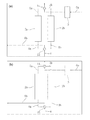
- FIG. 1 is a schematic drawing of an apparatus for treating air according to one illustrative embodiment.
- FIG. 2 is a schematic drawing of a dehumidifying part according to one illustrative embodiment.
- FIG. 3 is a schematic drawing of an apparatus for treating air according to one illustrative embodiment.
- FIG. 4 is a schematic drawing of an apparatus for treating air according to one illustrative embodiment.
- FIG. 5 is a schematic drawing of an apparatus for treating air according to one illustrative embodiment.
- FIG. 6 is a schematic drawing of an apparatus for treating air according to one illustrative embodiment.
- FIG. 7 is a schematic drawing of an apparatus for treating air according to one illustrative embodiment.
- FIG. 8 is a schematic drawing of an apparatus for treating air according to one illustrative embodiment.
- FIG. 9 is a schematic drawing of an apparatus for treating air according to one illustrative embodiment.
- FIG. 10 is a schematic drawing of an apparatus for treating air according to one illustrative embodiment.
- FIG. 11 is a schematic drawing of an apparatus for treating air according to one illustrative embodiment.
- FIG. 12 is a result of a water adsorption experiment according to one illustrative embodiment.
- FIG. 13 is a result of a water desorption experiment according to one illustrative embodiment.
- FIG. 14 is a result of a water desorption experiment according to one illustrative embodiment.
- FIG. 1 is a schematic drawing of an apparatus for treating air according to one illustrative embodiment.
- an apparatus for treating air includes a case ( 1 ) for forming the outside, a dehumidifying part ( 2 ) placed in the case ( 1 ) including an adsorbent, an inlet passage ( 4 ) for providing air having moisture to the dehumidifying part ( 2 ) from outside, and an outlet passage ( 5 ) for discharging dehumidified air by the dehumidifying part ( 2 ).
- a regeneration passage ( 6 ) for receiving air outside the apparatus for treating air and/or circulating air in the apparatus for treating air is placed inside the case ( 1 ) of the apparatus for treating air in order to regenerate the adsorbent of the dehumidifying part ( 2 ) to which moisture was adsorbed, and a heating part ( 3 ) is placed on the regeneration passage ( 6 ).
- the heating part ( 3 ) can mean any heating source providing heat to the air passing through the regeneration passage ( 6 ).
- the heating part ( 3 ) may heat the air passing through the regeneration passage ( 6 ) by directly delivering heat energy, or may heat the air passing through the regeneration passage ( 6 ) by providing air of high temperature heated outside the apparatus for treating air, but not limited to a specific method.
- the heating part ( 3 ) may include any conventional heating device such as the heating coil.
- a ventilation fan (not illustrated) may be placed in the inlet passage ( 4 ), outlet passage ( 5 ) and/or regeneration passage ( 6 ) in order to proceed air in the direction illustrated in FIG. 1 .
- an air filter (not illustrated) may be further placed at the dehumidifying part ( 2 ) and/or heating part ( 3 ) in order to eliminate dirt, dust, etc. included in the air.
- the dehumidifying part ( 2 ) may include a cylinder-shaped dehumidifying rotor, and the dehumidifying rotor is placed to rotate in a certain velocity with respect to the central axis (A).
- the dehumidifying part ( 2 ) including a dehumidifying rotor includes an adsorption area ( 11 ) through which air received from the inlet passage ( 4 ) passes, and a regeneration area ( 12 ) through which air received from the regeneration passage passes.
- the position of the adsorption area ( 11 ) and regeneration area ( 12 ) is relatively determined with respect to the position of the inlet passage ( 4 ) and regeneration passage ( 6 ).
- the area ratio of the adsorption area ( 11 ) and regeneration area ( 12 ) with respect to the total area of the dehumidifying rotor may be suitably determined depending on the dehumidifying amount and regeneration efficiency.
- the apparatus for treating air may include at least two dehumidifying rotors connected in series and/or in parallel, as needed. In case the dehumidifying part ( 2 ) includes two or more dehumidifying rotors, the dehumidifying efficiency per volume of dehumidifying part may increase.
- air received from outside through the inlet passage ( 4 ) is provided to the adsorption area ( 11 ) of the dehumidifying part ( 2 ), and air is dehumidified by the adsorbent within the adsorption area ( 11 ).
- Air dehumidified by passing through the adsorption area ( 11 ) of the dehumidifying part ( 2 ) is discharged outside through the outlet passage ( 5 ).
- the adsorption area ( 11 ) of the dehumidifying part ( 2 ) to which moisture was adsorbed moves to the area bordering the regeneration passage ( 6 ) by the rotation of the dehumidifying part ( 2 ) and becomes the regeneration area ( 12 ).
- the air moving through the regeneration passage ( 6 ) (air outside the apparatus for treating air and/or circulating air in the apparatus for treating air) is heated by the heating part ( 3 ), it passes through the regeneration area ( 12 ) of the dehumidifying part ( 2 ).
- the heated air contacts the adsorbent of the regeneration area ( 12 ) to which moisture was adsorbed, the moisture adsorbed is desorbed.
- moisture adsorbed at the adsorption area ( 11 ) is removed at the regeneration area ( 12 ), and air is dehumidified by the adsorbent regenerated in the regeneration area ( 12 ) at the adsorption area ( 11 ). Accordingly, air is dehumidified continually, and dehumidified air can be provided.
- FIG. 3 is a schematic drawing of the apparatus for treating air further including a heat exchanger ( 7 ) according to one illustrative embodiment.
- the apparatus for treating air illustrated in FIG. 3 is the same as the apparatus for treating air according to FIG. 1 except that it further includes a heat exchanger ( 7 ) for exchanging heat between the air in the outlet passage ( 5 ) and the air in the regeneration passage ( 6 ).
- a heat exchanger ( 7 ) for exchanging heat between the air in the outlet passage ( 5 ) and the air in the regeneration passage ( 6 ).
- the process where moisture is adsorbed to the adsorbent of the dehumidifying part ( 2 ) in the dehumidifying step is an exothermic process generating diluted heat.
- the process where moisture is desorbed from the adsorbent in the regenerating step is an endothermic process requiring reaction heat.
- the heat exchanger ( 7 ) exchanges heat between the air before passing through the heating part ( 3 ) at the regeneration passage ( 6 ) and the air after passing through the adsorption area ( 11 ) of the dehumidifying part ( 2 ).
- heat exchanger ( 7 ) By the heat exchanger ( 7 ), air dehumidified by passing through the adsorption area ( 11 ) can be cooled and air moving through the regeneration passage ( 6 ) (air outside the apparatus for treating air and/or circulating air in the apparatus for treating air) can be preheated (recovering heat) at the same time. In case of additionally using a heat exchanger ( 7 ), the efficiency of the energy spent for operating the apparatus for treating air can be increased.
- the heat exchanger ( 7 ) may include a cylinder-shaped rotating rotor having a honeycomb structure.
- a plurality of passages may be formed along the axial direction of the rotating rotor, and the inner surface of the passage may be treated with a material that easily transfers heat, for example metals such as aluminum.
- the rotating rotor is divided into a heating area and a cooling area, and the heating area and the cooling area may alternate with each other by the rotation of the driving motor connected to the rotating rotor.
- the dehumidifying operation and cooling operation of the apparatus for treating air are explained hereinafter.
- the air (outside, high temperature) received from the inlet passage ( 4 ) is dehumidified by passing through the adsorption area ( 11 ) of the dehumidifying part ( 2 ), and temperature may increase a little by the adsorption heat.
- Dry air is cooled after passing through the heat exchanger ( 7 ) (e.g., cooling area of the rotating rotor), and the dry air is provided indoor through the outlet passage ( 5 ).
- air (indoor, low temperature) received from the regeneration passage ( 6 ) is heated after passing through the heat exchanger ( 7 ) (e.g., heating area of the rotating rotor).
- the heated air After being heated by the heating part ( 3 ), the heated air passes through the regeneration area ( 12 ) of the dehumidifying part ( 2 ). As the heated air contacts the adsorbent of the regeneration area ( 12 ) to which moisture is adsorbed, the adsorbed moisture is desorbed.
- latent heat load is treated by the dehumidifying part ( 2 ) and sensible heat load is treated by the heat exchanger ( 7 ).
- the apparatus has an energy efficiency greater than that of the condensing type cooling apparatus.
- air can be dehumidified and cooled efficiently at the same time.
- FIG. 4 is a schematic drawing of the apparatus for treating air further including a cooling part ( 8 ) according to one illustrative embodiment.
- the apparatus for treating air illustrated in FIG. 4 is the same as the apparatus for treating air according to FIG. 3 except that a cooling part ( 8 ) is further placed in the outlet passage ( 5 ).
- a cooling part ( 8 ) is further placed in the outlet passage ( 5 ).
- the cooling part ( 8 ) may include an conventional cooling coil, a condensing type cooling apparatus, an evaporating type cooling apparatus, a combination of any two or more thereof, but it is not limited to a specific cooling method.
- the temperature of the air dehumidified by the dehumidifying part ( 2 ) and cooled by the heat exchanger ( 7 ) gets lower by passing through the cooling part ( 8 ).
- Latent heat load may be treated by the dehumidifying part ( 2 ) and sensible heat load may be treated by the cooling part ( 8 ).
- the humidity and temperature of the air provided can be controlled independently.
- FIG. 5 is a schematic drawing of the apparatus for treating air according to one illustrative embodiment.
- the apparatus for treating air is the same as the apparatus for treating air according to FIG. 1 except that the regeneration passage ( 6 ) is placed to circulate the heating part ( 3 ), the adsorption area ( 11 ) of the dehumidifying part ( 2 ) and the condenser ( 9 ).
- the regeneration passage ( 6 ) is placed to circulate the heating part ( 3 ), the adsorption area ( 11 ) of the dehumidifying part ( 2 ) and the condenser ( 9 ).
- moisture included in the air that passed through the regeneration area ( 12 ) of the dehumidifying part ( 2 ) is liquefied to water at the condenser ( 9 ), and the liquefied water is discharged outside or to a separate storing part through a drainage ( 13 ).
- Air dehumidified by the condenser ( 9 ) moves to the heating part ( 3 ) again.
- some of the air circulating the regeneration passage ( 6 ) may be discharged outside through a suitable means, and some of the air received to the apparatus for treating air from outside may be included in the circulated air of the regeneration passage ( 6 ).
- the apparatus for treating air may further include a heat exchanger ( 7 ) at the outlet passage ( 5 ) and regeneration passage ( 6 ) and/or a cooling part ( 8 ) at the outlet passage ( 5 ) (not illustrated).
- FIG. 6 is a schematic drawing of the apparatus for treating air according to one illustrative embodiment.
- the apparatus for treating air is the same as the apparatus for treating air according to FIG. 1 except that a regeneration passage ( 6 ) is placed to circulate the heating part ( 3 ), the adsorption area ( 11 ) of the dehumidifying part ( 2 ) and the heat exchanger ( 7 ′).
- a regeneration passage ( 6 ) is placed to circulate the heating part ( 3 ), the adsorption area ( 11 ) of the dehumidifying part ( 2 ) and the heat exchanger ( 7 ′).
- the air of the inlet passage ( 4 ) passes through the heat exchanger ( 7 ′) before being provided to the dehumidifying part ( 2 ).
- the air of the regeneration passage ( 6 ) passes through the regeneration area ( 12 ) of the dehumidifying part ( 2 ), and then passes through the heat exchanger ( 7 ′) before being provided to the heating part ( 3 ) again.
- the heat exchanger ( 7 ′) exchanges heat between the air in the regeneration passage ( 6 ) of which moisture is adsorbed at the dehumidifying part ( 2 ) and the air in the inlet passage ( 4 ) provided from outside.
- the apparatus for treating air may further include a heat exchanger ( 7 ) at the outlet passage ( 5 ) and regeneration passage ( 6 ) and/or further include a cooling part ( 8 ) at the outlet passage ( 5 ) (not illustrated).
- the apparatus for treating air including a dehumidifying part ( 2 ) can be classified into outside-air type unit, inside-circulation type unit or mixed outside-air type unit depending on how air is received from outside.
- the outside-air type can be used when there is dust in the subject area for treating air and it is difficult to recirculate dry air.
- the inside-circulation type can be used for places where it is not necessary to receive air from outside such as a storehouse, or an indoor room where outside unit is not installed.
- the mixed outside-air type is a method used by mixing return air, which can be used when controlling temperature and moisture at high level is required.
- FIG. 7 is a schematic drawing of the apparatus for treating air according to one illustrative embodiment.
- the apparatus for treating air according to the present embodiment has two parts of two-bed switching type dehumidifying parts.
- the two-bed switching type apparatus for treating air includes two parts of dehumidifying parts ( 2 a , 2 b ) and two switch valves ( 14 , 15 ).
- the two parts of dehumidifying parts ( 2 a , 2 b ) may operate for dehumidification and for regeneration alternately by switch valves ( 14 , 15 ) converting direction of air flow.
- switch valve ( 15 ) provides wet air received from the inlet passage ( 4 ) to the dehumidifying part ( 2 b ) through a pathway ( 4 b ), so that dehumidification is performed at the dehumidifying part ( 2 b ) and dehumidified air is discharged through the pathway ( 5 b ) and switch valve ( 14 ).
- air dried for regeneration is received from a pathway ( 6 a ) and heated by the heating part ( 3 ), it is provided to the switch valve ( 14 ) and the switch valve ( 14 ) provides the heated air to the dehumidifying part ( 2 a ) through the pathway ( 5 a ) to perform regeneration at the dehumidifying part ( 2 a ).
- Air having moisture from the dehumidifying part ( 2 a ) is discharged outside through a pathway ( 6 b ) after passing through the pathway ( 4 a ) and switch valve ( 15 ).
- the switch valves ( 14 , 15 ) convert direction of air flow of the wet air and the air to be regenerated.
- wet air received from the inlet passage ( 4 ) is sent to the pathway ( 4 a ) by the switch valve ( 15 ), thus being provided to the dehumidifying part ( 2 a ) where regeneration is completed, and the air for regeneration received from the pathway ( 6 a ) is sent to the pathway ( 5 b ) by the switch valve ( 14 ), thus being provided to the dehumidifying part ( 2 b ) requiring regeneration.
- air dried by the dehumidifying part ( 2 a ) is discharged through the pathway ( 5 a ) and switch valve ( 14 ), and air having moisture from the dehumidifying part ( 2 b ) is discharged outside through the pathways ( 4 b ) and ( 6 b ).
- two parts of dehumidifying parts ( 2 a , 2 b ) can be operated continually for adsorption or desorption by switch valves ( 14 , 15 ) converting direction of airflow.
- FIG. 8 is a schematic drawing of the apparatus for treating air according to one illustrative embodiment.
- the apparatus for treating air according to one embodiment includes two adsorbing parts ( 23 , 24 ) including adsorbent capable of adsorbing or desorbing a refrigerant alternately; a condenser ( 21 ) capable of condensing the refrigerant desorbed at the adsorbing part; an evaporator ( 22 ) capable of providing a cooling effect outside by evaporating the refrigerant; a refrigerant passage connecting the adsorbing part ( 21 ), condenser ( 21 ) and evaporator ( 22 ) and enabling the refrigerant to flow; and four flow control valves (V 1 , V 2 , V 3 , V 4 ) placed on the refrigerant passage, where the evaporator and the condenser are placed respectively between the two adsorbing parts ( 23 , 24 ).
- the valve (V 1 ) is placed between the condenser ( 21 ) and adsorbing part ( 23 ), the valve (V 2 ) is placed between the adsorbing part ( 23 ) and evaporator ( 22 ), the valve (V 3 ) is placed between the evaporator ( 22 ) and adsorbing part ( 24 ), and the valve (V 4 ) is placed between the adsorbing part ( 24 ) and condenser ( 21 ).
- the flow direction in the refrigerant passage is determined depending on whether the valves (V 1 , V 2 , V 3 , V 4 ) are open or closed.
- the flow of the refrigerant in the refrigerant passage may be accomplished by the pressure difference between each constitutional element, and a predetermined pump (not illustrated) may be placed on the refrigerant passage in order to facilitate the flow.
- the apparatus for treating air may include a predetermined controller (not illustrated).
- the controller may control the flow direction of the refrigerant by controlling the operation of the adsorbing parts ( 23 , 24 ), condenser ( 21 ), etc., and the opening and closing of the evaporator ( 22 ), valves (V 1 , V 2 , V 3 , V 4 ).
- a refrigerant capable of discharging heat when being adsorbed to the adsorbing part ( 23 , 24 ) or condensed at the condenser ( 21 ), and capable of absorbing heat when being desorbed from the adsorbing part ( 23 , 24 ) or evaporated at the evaporator ( 21 ) may be used.
- a refrigerant in terms of cost, environment, etc., water can be used, but the refrigerant is not limited thereto, and alcohol (e.g., methanol, ethanol), ammonia, etc. can be used.
- the apparatus for treating air operates with closed refrigerant passage where refrigerant circulate (closed cycle).
- the apparatus for treating air operates in a vacuum or a condition close to a vacuum, thus reducing diffusion resistance of the refrigerant.
- the open and closed mode of the valves (V 1 , V 2 , V 3 , V 4 ) and the operation method of the adsorbing parts ( 23 , 24 ) according to the operation modes [A] ⁇ [D] refer to the following Table 1.
- valves (V 2 ) and (V 3 ) are open and valves (V 1 ) and (V 4 ) are closed.
- Heat is provided from any heating source to the adsorbing part ( 24 ) (e.g., heating fluid (H) such as hot water is provided), and the refrigerant adsorbed to the adsorbing part ( 24 ) is desorbed.
- Heat is eliminated from the adsorbing part ( 23 ) by any cooling means (e.g., cooling fluid (C) such as cooling water is provided), and the refrigerant received is adsorbed at the adsorbing part ( 23 ).
- Heat is eliminated from the condenser ( 21 ) by any cooling means (e.g., cooling fluid (C) such as cooling water is provided), and the refrigerant desorbed from the adsorbing part ( 24 ) is condensed at the condenser ( 21 ).
- cooling fluid (C) such as cooling water
- the refrigerant condensed evaporates at the evaporator ( 22 )
- heat is absorbed, and a cooling effect can be achieved.
- a chilled fluid F e.g., chilled water
- valves (V 1 ) and (V 4 ) are open and valves (V 2 ) and (V 3 ) are closed. Except that heat is eliminated from and the refrigerant is adsorbed to the adsorbing part ( 24 ), and heat is provided to and the refrigerant is desorbed from the adsorbing part ( 23 ), a cooling effect similar to that obtained in operation mode [A] can be obtained by the evaporator ( 22 ).
- operation mode [A] is performed again.
- a cooling effect can be provided continually by evaporation by operation of absorption and desorption alternately at the adsorbing part ( 24 ) and adsorbing part ( 23 ).
- Such adsorption type apparatus for treating air has advantages such that it causes less vibration and noise by having smaller driving parts, it provides a cooling effect without using a Freon type refrigerant which damages the ozone layer, it has high stability when using water as a refrigerant (in terms of toxicity, abrasion, combustability, etc.), it does not have the disadvantage of solution crystallization as the absorbing type, and it has a lower possibility for non-condensed gas (hydrogen, etc.) to be generated (no additional operation is required, and it is advantageous in maintaining a vacuum).
- the adsorbent including porous organic-inorganic hybrid materials of the adsorbing parts ( 23 ) and ( 24 ) can desorb the refrigerant at relatively low temperature, and thus waste heat of low temperature (e.g., about 50 ⁇ 90° C.) can be used as a heating source of the adsorbing part ( 23 , 24 ) for desorption.
- the heating source may be originated from heat discharged from cooling water or apparatus during various manufacturing processes, heat originated from engine or generator of transportation means such as vessel, train or automobile, or the like, but is not limited thereto.
- FIG. 9 is a schematic drawing of the apparatus for treating air according to one illustrative embodiment.
- the apparatus for treating air according to the present embodiment is a two-stage type (four-bed) apparatus for treating air. As illustrated in FIG. 9 , except that the apparatus includes adsorbing parts ( 23 , 24 , 25 and 26 ) and valves (V 1 , V 2 , V 3 , V 4 , V 5 and V 6 ), it is similar to the apparatus for treating air according to FIG. 8 .
- a cooling effect can be provided continually by evaporation by operation of absorption and desorption alternately at the adsorbing parts ( 23 , 24 , 25 and 26 ). Explanation on the constitution that overlaps with that of FIG. 8 is omitted.
- FIG. 10 is a schematic drawing of the apparatus for treating air according to one illustrative embodiment.
- the apparatus for treating air according to the present embodiment is a three-stage type (six-bed) apparatus for treating air. As illustrated in FIG. 9 , except that the apparatus includes adsorbing parts ( 23 , 24 , 25 , 26 , 27 and 28 ) and valves (V 1 , V 2 , V 3 , V 4 , V 5 , V 6 , V 7 and V 8 ), it is similar to the apparatus for treating air according to FIG. 8 . As illustrated, a cooling effect can be provided continually by evaporation by operation of absorption and desorption alternately at the adsorbing parts ( 23 , 24 , 25 , 26 , 27 and 28 ). Explanation on the constitution that overlaps with that of FIG. 8 is omitted.
- a cooling effect can be obtained.
- waste heat of low temperature discarded considerably can be recovered to be used.
- FIG. 11 is a schematic drawing of the apparatus for treating air according to one illustrative embodiment.
- the apparatus for treating air according to the present embodiment is similar to the apparatus for treating air according to FIG. 8 except for further including a refrigerant passage and valve (V 5 ) connecting the adsorbing part ( 23 ) and adsorbing part ( 24 ).
- the cooling capability may be improved by using the pressure difference within adsorbing part ( 23 ) and adsorbing part ( 24 ).
- the adsorption amount and desorption amount increase by heat-exchanging the latent heat of refrigerant vapor by controlling the valve (V 5 ) between adsorbing part ( 23 ) and adsorbing part ( 24 ), and the cooling capability increases as the concentration difference increases during adsorption and desorption at the adsorbing part.
- the valve (V 5 ) is open so that latent heat of the refrigerant vapor can be exchanged between adsorbing part ( 23 ) and adsorbing part ( 24 ), as in operation modes [B] and [E].
- a booster pump or compressor may be further placed between the adsorbing part and condenser ( 21 ).
- refrigerant vapor desorbed from the adsorbing part is compressed at high pressure, thus condensing the refrigerant at normal ambient temperature without eliminating heat from the condenser ( 21 ) using a separate cooling means.
- a water adsorbent can be used as an adsorbent at the dehumidifying parts ( 2 ), ( 2 a ) and ( 2 b ), and adsorbing parts ( 23 ), ( 24 ), ( 25 ), ( 26 ), ( 27 ) and ( 28 ).
- the adsorbent may include porous organic-inorganic polymer compounds (or porous organic-inorganic hybrid materials) formed by binding a central metal ion with an organic ligand.
- the porous organic-inorganic hybrid materials may be crystalline compounds with pores of a molecular size or nano size including both an organic material and an inorganic material within the framework structure.
- porous organic-inorganic hybrid materials is also referred to as porous coordination polymers [Angew. Chem. Intl. Ed., 43, 2334, 2004], or metal-organic frameworks (MOF) [Chem. Soc. Rev., 32, 276, 2003].
- the adsorbent may further include a dehumidifying agent such as silica gel, zeolite, activated alumina, lithium chloride, activated carbon, aluminum silicate, calcium chloride and calcium carbonate, etc., and if necessary, at least one or two of them may be mixed with the porous organic-inorganic hybrid materials and used as an adsorbent.
- a dehumidifying agent such as silica gel, zeolite, activated alumina, lithium chloride, activated carbon, aluminum silicate, calcium chloride and calcium carbonate, etc.
- the porous organic-inorganic hybrid materials have pores of a molecular size or nano size. In one embodiment, the pore size of the porous organic-inorganic hybrid materials may be about 0.3 ⁇ about 10 nm. In one embodiment, the average particle size of porous organic-inorganic hybrid materials is about 100 ⁇ m or less.
- the surface area of the porous organic-inorganic hybrid materials may be at least 300 m 2 /g. In another embodiment, the surface area of the porous organic-inorganic hybrid materials may be at least 500 m 2 /g, at least 700 m 2 /g, at least 1,000 m 2 /g, at least 1,200 m 2 /g, at least 1,500 m 2 /g or at least 1,700 m 2 /g, but is not limited thereto. In some embodiments, the surface area of the porous organic-inorganic hybrid materials may be 10,000 m 2 /g or less.
- the pore volume of the porous organic-inorganic hybrid materials may be at least 0.1 mL/g, or at least 0.4 mL/g. In another embodiment, the pore volume of the porous organic-inorganic hybrid materials may be 10 mL/g or less.
- the porous organic-inorganic hybrid materials may include metal components.
- the porous organic-inorganic hybrid materials may include, for example, at least one metal component selected from the group consisting of Sc, Y, Ti, Zr, Hf, V, Nb, Ta, Cr, Mo, W, Mn, Tc, Re, Fe, Ru, Os, Co, Rh, Ir, Ni, Pd, Pt, Cu, Ag, Au, Zn, Cd, Hg, Mg, Ca, Sr, Ba, Al, Ga, In, Tl, Si, Ge, Sn, Pb, As, Sb and Bi.
- the porous organic-inorganic hybrid materials may include at least one of transition metals of period 4 such as Ti, V, Cr, Mn, Fe, Co, Ni, Cu, Zn and Ga; transition metals of period 5 such as Y, Zr, Nb, Mo, Tc, Ru, Rh, Pd, Ag and Cd; and transition metals of period 6 such as Lu, Hf, Ta, W, Re, Os, Ir, Pt, Au and Hg.
- transition metals of period 4 such as Ti, V, Cr, Mn, Fe, Co, Ni, Cu, Zn and Ga
- transition metals of period 5 such as Y, Zr, Nb, Mo, Tc, Ru, Rh, Pd, Ag and Cd
- transition metals of period 6 such as Lu, Hf, Ta, W, Re, Os, Ir, Pt, Au and Hg.
- transition metals are chromium, vanadium, iron, nickel, cobalt, copper, titanium or manganese, coordination compounds are easily formed.
- the porous organic-inorganic hybrid materials may include typical elements such as magnesium, aluminum, silicon which may form a coordination compound, or lanthanoid series metals such as cerium, yttrium, terbium, europium, lanthanum.
- the porous organic-inorganic hybrid materials may be formed by coordination bonding with divalent to hexavalent metal ions.
- the divalent metal ion may be Ni 2+ , Cu 2+ , Co 2+ , Mg 2+ , Ca 2+ , Fe 2+ , Mn 2+ , Zn 2+ , etc.
- the trivalent metal ion may be Fe 3+ , Cr 3+ , Al 3+ , Mn 3+
- the porous organic-inorganic hybrid materials may be formed by coordination bonding with tetravalent, pentavalent, or hexavalent metal ions of Zr, Ti, Sn, V, W, Mo or Nb.
- metal components having antibacterial activity against various bacterium can be substituted within the porous organic-inorganic hybrid materials.
- metal components having antibacterial activity may include Ag(I), Cu(II or I), Ni(II), but are not limited thereto.
- an organic compound which may act as an organic ligand included in porous organic-inorganic hybrid materials are referred as a linker.
- the organic ligand has an organic compound having a functional group capable of coordination.
- functional groups that can coordinate may include, but not limit to, carbonic acid group (—CO 3 H), anion group of carbonic acid (—CO 3 ⁇ ), carboxyl, anion group of carboxylic acid, amino group (—NH 2 ), imino group
- amide group (—CONH 2 ), sulfonic acid group (—SO 3 H), anion group of sulfonic acid (—SO 3 ⁇ ), methanedithioic acid group (—CS 2 H), anion group of methanedithioic acid (—CS 2 ⁇ ), pyridine group, pyrazine group, etc.
- the organic ligand may include organic compounds having at least two sites for coordination, e.g. polydentate such as bidentate, tridentate, etc.
- the examples of the above organic ligand may be a neutral organic compound such as bipyridine, pyrazine, etc., anionic organic compounds, e.g., anions of carboxylic acid such as terephthalate, naphthalenedicarboxylate, benzenetricarboxylate, benzenetribenzoate, pyridinedicarboxylate, bipyridyldicarboxylate, etc., and cationic materials, if these have a site for coordination.
- any anions e.g., linear carboxylic acid anions such as formate, oxalate, malonate, succinate, glutamate, hexanedioate or heptanedioate and anions having non-aromatic rings such as cyclohexyldicarboxylate can be used, but is not limited thereto.
- the organic ligand can be dihydroxyterephthalate, or derivatives thereof.
- 2,5-dihydroxyterephthalate or derivatives thereof can be included.
- dihydroxyterephthalate having Cl, Br, I, NO 3 , NH 2 , COOH, SO 3 H, etc. in its benzene ring can be used.
- porous organic-inorganic hybrid materials can include copper terephthalate, iron terephthalate, manganese terephthalate, chromium terephthalate, vanadium terephthalate, aluminum terephthalate, titanium terephthalate, zirconium terephthalate, magnesium terephthalate, copper benzenetricarboxylate, iron benzenetricarboxylate, manganese benzenetricarboxylate, chromium benzenetricarboxylate, vanadium benzenetricarboxylate, aluminum benzenetricarboxylate, titanium benzenetricarboxylate, zirconium benzenetricarboxylate, magnesium benzenetricarboxylate, iron naphthalenedicarboxylate, chromium naphthalenedicarboxylate, aluminum naphthalenedicarboxylate, a derivative thereof, a solvate thereof, a hydrate thereof or combinations
- porous organic-inorganic hybrid materials may include nickel dihydroxyterephthalate, cobalt dihydroxyterephthalate, magnesium dihydroxyterephthalate, manganese dihydroxyterephthalate, or iron dihydroxyterephthalate, a derivative thereof, a solvate thereof, a hydrate thereof or combinations thereof.
- crystallized porous organic-inorganic hybrid materials may include two or more ligands from terephthalate, benzenetribenzoate or benzenetricarboxylate, and metal elements.
- M Cu,
- X may be partially substituted with —OH in the formula above.
- porous organic-inorganic hybrid materials having halogen element can be prepared by using metal halides or a hydrate thereof as a metal precursor.
- porous organic-inorganic hybrid materials can be prepared by reacting a metal precursor with an organic compound which may act as an organic ligand.
- porous organic-inorganic hybrid materials can be prepared by a method including heating a reaction mixture including a metal precursor, an organic compound which may act as an organic ligand, and a solvent.
- the method of preparing porous organic-inorganic hybrid materials may include:
- a metal precursor can be a metal itself such as Sc, Y, Ti, Zr, Hf, V, Nb, Ta, Cr, Mo, W, Mn, Tc, Re, Fe, Ru, Os, Co, Rh, Ir, Ni, Pd, Pt, Cu, Ag, Au, Zn, Cd, Hg, Mg, Ca, Sr, Ba, Al, Ga, In, Tl, Si, Ge, Sn, Pb, As, Sb, Bi, etc., or a compound having such metal elements.
- a metal precursor can be transition metals or compounds having transition metals.
- a metal precursor may include typical elements such as magnesium, calcium, aluminum, and silicon with which a coordination compound can be made, or a metal of lanthanoid series such as cerium and lanthanum.
- a compound having metal elements used as a metal precursor can be metal salts such as metal halide, metal nitrate, metal sulfate, metal acetate, metal carbonyl or metal alkoxide, or a hydrate thereof.
- Halogen can be referred to F, Cl, Br, or I.
- metal precursors can be copper chlorides (e.g., CuCl 2 ), iron chlorides (e.g., FeCl 3 ), manganese chlorides (e.g., MnCl 2 ), chromium chlorides (e.g., CrCl 3 ), vanadium chlorides (e.g.
- a metal precursor may include copper nitrate, iron nitrate, manganese nitrate, chromium nitrate, vanadium nitrate, zinc nitrate, or a hydrate thereof, but is not limited thereto.
- an organic compound which may act as an organic ligand includes an organic compound having functional groups that can coordinate.
- functional groups that can coordinate may include, but not limit to, carbonic acid group (—CO 3 ), anion group of carbonic acid (—CO 2 ⁇ ), carboxyl, anion group of carboxylic acid, amino group (—NH 2 ), imino group
- amide group (—CONH 2 ), sulfonic acid group (—SO 3 H), anion group of sulfonic acid (—SO 3 ⁇ ), methanedithioic acid group (—CS 2 H), anion group of methanedithioic acid (—CS 2 ⁇ ), pyridine group, pyrazine group, etc.
- examples of an organic compound which can act as an organic ligand may include an organic compound such as bidentate or tridentate.
- the compound having at least two sites for coordination can derive stable porous organic-inorganic hybrid materials.
- the examples of the organic compound which may act as an organic ligand may be a neutral organic compound such as bipyridine, pyrazine, etc., anionic organic compounds, e.g., anions of carboxylic acid such as terephthalate, naphthalenedicarboxylate, benzenetricarboxylate, benzenetribenzoate, pyridinedicarboxylate, bipyridyldicarboxylate, etc., and cationic materials, if these have a site for coordination.
- any anions e.g., linear carboxylic acid anions such as formate, oxalate, malonate, succinate, glutamate, hexanedioate and heptanedioate and anions having non-aromatic rings such as cyclohexyldicarboxylate can be used.
- an organic compound which may act as an organic ligand in addition to an organic compound having a site for coordination, an organic compound which has a potential site for coordination and thus can be converted into a form capable of forming a coordinate bond under reaction conditions can also be used.
- an organic acid such as terephthalic acid
- terephthalic acid converts into terephthalate after reaction and thus can bond to a metal component.
- examples of the organic compounds include organic acids such as benzenedicarboxylic acid, naphthalenedicarboxylic acid, benzenetricarboxylic acid, naphthalenetricarboxylic acid, benzenetribenzoic acid, pyridinedicarboxylic acid, bipyridyldicarboxylic acid, formic acid, oxalic acid, malonic acid, succinic acid, glutamic acid, hexanedioic acid, heptanedioic acid and cyclohexyldicarboxylic acid; and an anion thereof; pyrazine, bipyridine, dihydroxyterephthalic acid, etc.
- at least one organic compound can be used in combination.
- a solvent which can dissolve both metal precursors and organic compound which may act as an organic ligand can be used.
- examples of the solvent include water, alcohol, ketones, hydrocarbons, N,N-dimethylformamid (DMF), N,N-diethylformamid (DEF), N,N-dimethylacetylamid (DMAc), acetonitrile, dioxane, chlorobenzene, pyridine, N-methylpyrrolidone (NMP), sulfolane, tetrahydrofuran (THF), gamma butyrolactone, alicyclic alcohol such as cyclohexanol, etc., but are not limited thereto.
- At least two solvents can be mixed together.
- the solvent one or a mixture of at least two selected from water; mono or poly alcohols having 1 ⁇ 10 carbon atoms such as methanol, ethanol, propanol, alkylene polyol such as ethylene glycol, glycerol, polyalkylene polyol such as polyethylene glycol; ketones having 2 ⁇ 10 carbon atoms such as acetone, methylethylketone, acethylacetone and hydrocarbons having 4 ⁇ 20 carbon atoms (e.g., a linear or cyclic alkanes having 4 ⁇ 10 carbon atoms such as hexane, heptane, octane and toluene) can be used.
- water, EG, DMF or THF can be used as said solvent.
- the molar ratio of the metal precursor and the organic compound which may act as the organic ligand can be properly adjusted depending on the kind of the metal component and organic compound. In one embodiment, the molar ratio of the metal precursor and the organic compound which may act as the organic ligand is 1:0.1 ⁇ 500, but is not limited to it. In another embodiment, the molar ratio of the metal precursor and the organic compound which may act as the organic ligand can be 1:0.1 ⁇ 100 or 1:0.1 ⁇ 10.
- the heating temperature of the reaction mixture is not substantially limited. In some embodiments, the temperature can be at least room temperature. In another embodiment, the temperature can be at least 20° C., or at least 50° C., at least 60° C., at least 80° C. or at least 100° C. In some embodiment, the heating temperature can be 250° C. or lower.
- the reactor pressure is not substantially limited.
- the reaction may be performed at autogeneous pressure of the reaction materials at reaction temperature within the reactor.
- the reaction may be performed at high pressure by adding inert gas such as nitrogen or helium.
- porous organic-inorganic hybrid materials with crystallinity can be prepared by a method including preparing the reaction solution including a mixture of at least one inorganic metal precursor, at least one organic compound which may act as at least one ligand and a solvent; and forming porous organic-inorganic hybrid materials with crystallinity by reacting the reaction solution, where the reaction is conducted under the pressure of about 3 atm or less.
- Porous organic-inorganic hybrid materials with crystallinity can be synthesized by any conventional method such as the hydrothermal synthesis, solvothermal synthesis, irradiating microwave sono synthesis, etc.
- porous organic-inorganic hybrid materials can be prepared by a solvent dissolving at near room temperature or a hydrothermal synthesis at high temperature using water solvent.
- porous organic-inorganic hybrid materials with crystallinity can be prepared by a solvothermal synthesis using an organic solvent [Microporous Mesoporous Mater., vol. 73, p. 15 (2004)].
- porous organic-inorganic hybrid materials with crystallinity are in general prepared by a method of using water or an appropriate organic solvent, conducting a reaction at a temperature higher than the boiling point of the solvent or reaction solution and autogenous pressure, and performing a crystallization, similarly to the method for preparing inorganic porous materials such as zeolite and mesoporous compounds.
- a metal ion or metal compound and an organic ligand are stirred or microwaves are irradiated on them for a certain time in the presence of a solvent, so that the organic compound coordinates with the metal to form a crystallization nucleus. Then, crystallization is performed by irradiating microwaves to the reaction solution in which crystallization nuclei are formed.
- the reaction in order to remarkably increase the crystallizing rate under the synthesis condition of high concentration and control the crystal growth rate and the automatic adsorption rate of solvent during reaction, it is preferable to carry out synthesis at a low pressure of 3 atm or less. In some embodiments, the reaction may be carried out at 2.5 atm or less, or at 2 atm or less. Without being bound by theory, it is believed that even in case of using a solvent having a boiling point lower than the reaction temperature, the pressure does not increase since the crystal of porous organic-inorganic hybrid materials adsorbs the solvent rapidly.
- porous organic-inorganic hybrid materials with crystallinity are prepared according to a method performed at a low pressure of 3 atm or less, in spite of such a low pressure condition, porous organic-inorganic hybrid materials have high crystallinity and uniform distribution of particle size can be provided regardless of the presence or absence of a crystallization agent (e.g., hydrofluoric acid).
- a crystallization agent e.g., hydrofluoric acid
- the reaction is carried out under the condition where a metal precursor is present in a reaction solution in a high concentration.
- the molar ratio of the solvent to the inorganic metal precursor in the reaction solution is 100 or less.
- the molar ratio of the solvent to the inorganic metal precursor in the reaction solution is 60 or less, 50 or less, or 25 or less.
- the method for preparing porous organic-inorganic hybrid materials with crystallinity may further include purifying an impurity in the porous organic-inorganic hybrid materials obtained in the step 2 by treatment with an inorganic salt, an acid adjuster, a solvent, or a mixture thereof.
- This step may be additionally carried out for increasing the surface area of porous organic-inorganic hybrid materials by removing the chelated organic or inorganic impurities from the pores by using a solvent, inorganic salt, acid adjuster or a mixture thereof, in order to remove metal salts and their counter ions or organic ligands present in the pores of porous organic-inorganic hybrid materials with crystallinity.
- examples of the inorganic salt include a monovalent or divalent cation selected from the group consisting of ammonium (NH 4 + ), alkali metals and alkaline earth metals, and a monovalent or divalent anion selected from the group consisting of carbonate anion (CO 3 2 ⁇ ), nitrate ion and sulfate ion.
- examples of the inorganic salt include salts having Ca 2+ or Mg 2+ as a divalent cation.
- examples of the inorganic salt include salts having F ⁇ , I ⁇ or Br ⁇ as a monovalent anion.
- examples of the inorganic salt include salts having a monovalent cation and divalent anion.
- examples of the inorganic salt include NH 4 F, KF, KI, or KBr.
- an acid adjuster can reduce the time for the purification of porous organic-inorganic hybrid materials with crystallinity, and thus can make the process economical.
- a basic compound can be used as a pH adjuster.
- ammonia or potassium hydroxide can be used.
- the porous organic-inorganic hybrid materials have an unsaturated metal site, and a surface-functionalizing compound binds to the unsaturated metal site.
- the surface of the porous organic-inorganic hybrid materials may be modified or functionalized by the binding of a surface-functionalizing compound having various functional groups to the unsaturated metal site of the porous organic-inorganic hybrid material.
- unsaturated metal site refers to an accessible coordination site at the metal after removal of water or solvent from the porous organic-inorganic hybrid material. It also refers to a site where a compound having a functional group can form a covalent bond or coordinate bond.
- Such surface-functionalization can be carried out according to the disclosure of Korean Patent Publication No. 10-0864313, 10-0816538, etc., incorporated herein by reference.
- a surface-functionalizing compound which can be bonded to unsaturated metal sites may be at least one selected from organic substances, inorganic substances, ionic liquids, or organic-inorganic hybrid substances.
- the organic substance may be at least one selected from among the compounds represented by Formulas 1 to 3 below: H 2 N-M-R1 [Formula 1] HS-M-R2 [Formula 2] (OH) 2 OP-M-R3 [Formula 3] where M is an alkylene or aralkylene group of C 1 ⁇ C 20 including or not including unsaturated hydrocarbons, and each of R1, R2 and R3 is independently an organic alkylene or aralkylene group, unsubstituted or substituted with at least one selected from among halogen elements, a vinyl group (—C ⁇ CH 2 ), an amino group (—NH 2 ), an imino group (—NHR 14 ), a mercapto group (—SH), a hydroxyl group (—OH), a carboxylic acid group (—COOH), a sulfonic acid group (—SO 3 H), an alkoxy group (—OR) and a phosphoric group (—PO(OH) 2 ).
- M is
- polyoxometallate of [AlO 4 Al1 2 (OH) 24 (H 2 O) 12 ] 7+ or [PW 12 O 40 ] 4 ⁇ may be used.
- the polyoxometallate may include a structure of Keggin anion [(XM 12 O 40 ) n ⁇ , where n is an integer of 1 ⁇ 10; X is P, Si, H, Ga, Ge, V, Cr, Me or Fe; and M is at least one selected from among W, Mo, and Co], a structure of Lindqvist anion [(M 6 O 19 ) n ⁇ , where n is an integer of 1 ⁇ 10; and M is W, Mo, Ta, V or W], a structure of Anderson-Evans anion [(M x (OH) 6 M 6 O 18 ) n ⁇ , where n is an integer of 1 ⁇ 10; M x is Cr, Ni, Fe, or Mn; and M is Mo, or W] or [(M 4 (XM 12 O 40 )
- the ionic liquids may be at least one salt selected from ammonium, phosphonium, sulphonium, pyrrolidinium, imidazolium, thiazolium, pyridium or triazolium.
- the organic-inorganic hybrid substances may be organic metal compounds.
- compounds including organic silicone may be used as organic silane compounds.
- Specific examples of the organic silane compounds may include silylating agents, silane coupling agents, silane polymers, and mixtures thereof.
- organic silane compounds can be easily bonded to the coordinatively unsaturated metal sites of the porous organic-inorganic hybrid materials and are stable after bonding.
- an organic silane compound having an alkoxy group at one side thereof and having an alkyl group, an alkenyl group and an alkynyl group having a functional group selected from an amino group and a mercapto group at the other side, can form stable bonds with the porous organic-inorganic hybrid materials and has high catalytic activity.
- the organic metal compounds as the organic-inorganic hybrid substance can be at least one selected from compounds represented by Formulas 4 to 11 below: Si(OR 1 ) 4-x R x (1 ⁇ x ⁇ 3) [Formula 4] Si(OR 3 ) 4-(y+z) R 2 y Z z (1 ⁇ y+z ⁇ 3) [Formula 5] Si(OR 4 ) 4-a R 5 a Si(1 ⁇ a ⁇ 3) [Formula 6] Z 1 b (OR 6 ) 3-b Si-A-Si(OR 7 ) 3-C Z 2 C (0 ⁇ b ⁇ 2, 0 ⁇ c ⁇ 2) [Formula 7] R 8 e M 1 (OR 9 ) 4-e (1 ⁇ e ⁇ 3) [Formula 8] R 10 g M 2 Z 3 f (OR 11 ) 4-(f+g) (1 ⁇ f+g ⁇ 3) [Formula 9] M 3 (OR 12 ) h (1 ⁇ h ⁇ 2) [Formula 10] M 4 (OR 13 )
- the mixtures of two or more substances may be used, or the method sequentially using other substances after the use of one of the substance may be used.
- the porous organic-inorganic hybrid materials or mesoporous organic-inorganic material is first reacted with organic substances or organic metal compounds, and in the second step subsequently reacted with ionic liquids or inorganic polyoxometallates, thereby preparing a surface-functionalized porous organic-inorganic hybrid materials or mesoporous organic-inorganic material.
- This method is advantageous in that the dissolution of metals, which are active materials, can be prevented when functional groups are secondarily supported with the metals.
- the porous organic-inorganic hybrid materials may be provided in a form of powder, thin film, membrane, pellet, ball, foam, slurry, paste, paint, honeycomb, bead, mesh, fiber, corrugated sheet, etc.
- the porous organic-inorganic hybrid materials in a form of thin film or membrane can be prepared by the method of immersing a substrate to a reaction solution and heating the substrate.
- the amount of organic or inorganic binder in shaped bodies may be 50% by weight or less based on the total weight of the shaped bodies.
- examples of inorganic binders may include, but are not limited to, silica, alumina, boehmite, zeolite, mesoporous material, carbon, graphite, layer-structured compound, metal alkoxide, metal halide, etc.
- examples of organic binders may include, but are not limited to, alcohol, cellulose, polyvinylalcohol, polyacrylate, etc.
- the ceramic paper is single-side corrugated in a form of the corrugated paper and then a cylindrical honeycomb is prepared by rolling the single-side corrugated paper to become a cylindrical shape.
- the ceramic paper, single-side corrugated paper or cylindrical honeycomb as a substrate, is immersed in a reaction solution, and heated to prepare a dehumidifying part including porous organic-inorganic hybrid materials.
- the porous organic-inorganic hybrid materials described above has a great difference in its adsorptions at low and high temperatures, and accordingly is useful as an adsorbent.
- the porous organic-inorganic hybrid materials have the characteristics of being easily desorbed at low temperatures (for example, 100° C. or below), and having a large adsorption amount of water per unit weight of the porous organic-inorganic hybrid materials and/or having a high absorption rate.
- porous organic-inorganic hybrid materials may desorb 10% or more of the adsorbed water within 5 minutes at the water desorption temperature of 100° C. or below. In another embodiment, the porous organic-inorganic hybrid materials may desorb 20% or more, 40% or more, 60% or more, or 75% or more of the adsorbed water within 5 minutes at the water desorption temperature of 100° C. or below.
- porous organic-inorganic hybrid materials can adsorb 0.1 g to 3 g of an adsorbate per 1 g of porous organic-inorganic hybrid materials.
- the porous organic-inorganic hybrid materials can adsorb 0.1 g to 2 g of an adsorbate per 1 g of porous organic-inorganic hybrid materials at 100° C. or below, or 0.1 g or more, 0.2 g or more, 0.4 g or more or 0.5 g or more of an adsorbate per 1 g of porous organic-inorganic hybrid materials at 10° C. to 100° C.
- the porous organic-inorganic hybrid materials can adsorb 1 g or less, 0.9 g or less, 0.8 g or less 0.7 g or less of an adsorbate per 1 g of porous organic-inorganic hybrid materials at 10° C. to 100° C.
- the porous organic-inorganic hybrid materials has a large surface area and pores of a molecule size or nano size, and thus can be used as an adsorbent, air storage material, sensor, membrane, functional thin film, catalyst, catalyst carrier, etc.
- the porous organic-inorganic hybrid materials can encapsulate guest molecules smaller than their pore size or can separate the molecules according to the sizes of the molecules by using their pores.
- the adsorbent including the porous organic-inorganic hybrid materials can adsorb not only water, but also hydrogen, oxygen, nitrogen, hydrocarbon such as methane, paraffin or olefin, carbon monoxide, carbon dioxide, compound causing foul odor such as ammonia, compound having nitrogen such as trimethylamine, compound having sulfur such as methylsulfide or methylmercaptan, volatile organic compound (VOC) such as formaldehyde, acetaldehyde, etc.
- VOC volatile organic compound
- gases such as hydrocarbon, NOx, CO, VOC, etc. included in the air received from outside can be effectively adsorbed•removed, and especially, the air from which NOx, etc. are removed can be provided to any desired place.
- the dehumidifying part ( 2 ) may further include a catalyst component that can decompose various VOCs, but it is not limited to a specific catalyst.
- a catalyst component capable of decomposing VOCs together, the efficiency in removing gases can be increased by decomposing pollutant included in the air introduced from outside.
- said catalyst can be a metal catalyst including platinum, silver, gold, palladium, ruthenium, rhodium, osmium, iridium, manganese, copper, cobalt, chromium, nickel, iron, zinc, or a combination of one or more thereof.
- Said metal catalyst can be provided in various forms combined with a carrier such as aluminum, silica, zeolite, zirconia, ceria-zirconia, porous organic-inorganic hybrid materials mentioned above.
- a metal catalyst bonded with a carrier can be obtained by preparing catalyst powder by supporting metal salt including palladium ion and ion of transition metal such as copper, manganese, nickel, chromium, cobalt, etc. in a porous carrier, oxide carrier, etc.
- a catalyst slurry can be prepared by combining said catalyst powder and an adsorbent such as porous organic-inorganic hybrid materials with binder such as bentonite, silica colloid, methyl cellulose, etc., and a honeycomb type monolith catalyst can be prepared by wet-coating said catalyst slurry on a honeycomb carrier surface.
- This metal catalyst can be prepared as disclosed in Korean Patent Laid-Open No. 10-2001-0037883 incorporated herein by reference.
- a metal catalyst may be a metal-supported organic-inorganic mesoporous material catalyst including a lipophilic group in its skeleton of mesoporous material, and an active metal that is well dispersed in pores of a porous material.
- the organic-inorganic mesoporous materials supporting a metal component can be prepared by, but are not limited to, a method including: preparing a mixture by stirring the noble metal compounds including an ion of metal such as platinum, silver, gold, palladium, ruthenium, rhodium, osmium, iridium, etc.
- Such metal catalyst can be prepared as disclosed in Korean Patent Registration Publication No. 10-0816485 incorporated herein by reference.
- a metal catalyst may be a catalyst in which at least one metal component are supported on alumina, hydrophobic zeolite, etc.
- metal components may include noble metals such as platinum, palladium, etc. or transition metals such as copper, cobalt, chromium, zinc, iron, silver, nickel, etc.
- hydrophobic zeolite may include, but are not limited to, MFI (HZSM-5), FAU (HY), Mordenite (HMOR), Beta (H-Beta), etc.
- a metal catalyst may be a provided in a form of pellet, honeycomb, etc. Korean Patent Registration Publication No. 10-0578106 incorporated herein by reference may be referred to such metal catalyst.
- a dehumidifying part in case of using an adsorbent including the porous organic-inorganic hybrid materials in an apparatus for treating air, since a dehumidifying part is in a state of low humidity, microorganism can be reduced when passing through the dehumidifying part, the propagation of mold or bacteria can be inhibited, and airborne bacteria or mold can be reduced in indoor atmosphere.
- the metal component having an antibacterial activity against various bacteria is substituted in the porous organic-inorganic hybrid materials, bacteria, etc. included in the air received from outside is removed due to an antibacterial function so that fresh air can be provided to a desired place.
- An apparatus for treating air including the porous organic-inorganic hybrid materials can be used not only in ordinary houses, but also in various industries such as a chemical industry, food industry, electric•electronic industry, precision machinery industry, textile industry, printing industry, military industry, etc. that require a dehumidification and/or conditioning, cooling or treating air.
- the reaction mixture was cooled to room temperature, centrifuged, washed (with distilled water) and dried to obtain porous organic-inorganic hybrid materials (Fe-BTC) with a surface area of 2,200 m 2 /g.
- a water adsorption test was performed by a gravimetric method. At a relative humidity of 60%, the water adsorption amount per weight of the adsorbent was 0.8 g/g. As such, it can be shown that the porous organic-inorganic hybrid materials easily adsorb and desorb water even at a low temperature of 100° C. or below, it can achieve a very excellent efficiency in humidifiers, dehumidifiers, etc.
- Porous organic-inorganic hybrid materials were prepared by using aluminum nitrate hydrate, instead of iron nitrate of Example 3.
- the surface area of Al-BTC prepared having the same structure was 1,720 m 2 .
- the XRD pattern of the chromium terephthalate crystal obtained from the present example was consistent with the values published in a reference [Science 23, 2040, 2005].
- the adsorption amount was 1,200 ml/g and the surface area was 3,800 m 2 /g at a relative pressure of 0.5, thus obtaining a high surface area.
- the particle size was ⁇ 500 nm.
- Porous organic-inorganic hybrid materials were prepared in the same manner as in Example 7 except that the organic-inorganic hybrid materials was prepared by heating by using microwaves instead of electric heating as a heat source.
- microwave heating after mounting the Teflon reactor including the mixed solution prepared in Example 7 on a microwaves reactor (CEM company, model Mars-5) and then raising the temperature to 180° C. by irradiating microwaves (2.54 GHz), crystallization was performed while maintaining the reaction material at 180° C. for 30 minutes. Then, the reaction materials were cooled to room temperature, centrifuged, washed (with distilled water) and dried to obtain porous organic-inorganic hybrid materials (Fe-BTC).
- Porous organic-inorganic hybrid materials were prepared in the same manner as in Example 7 except that VCl 3 was used instead of FeCl 3 as in Example 7.
- the X-ray diffraction pattern shows that the material having the same structure as in Example 7 was obtained.
- the electron microscope photograph shows that the porous organic-inorganic hybrid materials having uniform particle size of 100 nm was obtained.
- the reaction mixture was irradiated with supersonic waves at room temperature, and a pre-treatment was performed for 5 minutes to make a reaction mixture uniform and easily form nuclei.
- the temperature was raised to 140° C. for 2 minutes by irradiating microwaves of 2.54 GHz. Thereafter, after reacting it while maintaining the reaction mixture at 140° C.
- Porous organic-inorganic hybrid materials were prepared in the same manner as in Example 8 except that Fe was used instead of FeCl 3 as in Example 8.
- the X-ray diffraction pattern shows that the material having the same structure as in Example 8 was obtained, and the surface area of the obtained porous organic-inorganic hybrid materials was 1,300 m 2 /g.
- Ni-DHT porous organic-inorganic hybrid materials
- APS was coordinated in Cr-BDC from that the adsorption peak was detected at 2,800 ⁇ 3,000 cm ⁇ 1 and 3,200 ⁇ 3,400 cm ⁇ 1 , which corresponds to an amino group (—NH 2 ) and ethyl group (—CH 2 CH 2 —) of APS by Infrared Spectroscopy.
- Fe-BTC powder obtained from said Example 3 100 g of Fe-BTC powder obtained from said Example 3 is mixed with 600 g of water to make slurry solution. Then, the slurry solution was wet-coated on a pre-treated cordierite honeycomb (Corning Korea company, 200 cell, 15 ⁇ 15 ⁇ 5 cm) (honeycomb pre-treatment condition: it is treated with 1M-HNO 3 at 70° C. for 5 hours, washed with distilled water, and dried in the air at 600° C. for 5 hours). Then, the honeycomb on which the Fe-BDC adsorbent is coated is dried in an oven at 70° C. to support the Fe-BTC adsorbent in a honeycomb monolith support. The amount of Fe-BTC adsorbent supported therein is 30% by weight compared with the honeycomb support.
- the obtained Fe-BTC slurry was put in a cylinder type extruder, and the inside of the extruder was maintained in a vacuum state and extruded article was made at a slurry rotating speed of 50 rpm and a molding speed of 300 mm/min.
- the obtained extruded article was dried at 80° C. for 12 hours, and then was heated by a calcining furnace at 120° C. for 2 hours.
- BET surface area of the final extrusion-molded article was 1750 m 2 /g.
- the reaction material was cooled to room temperature, washed with distilled water and dried to obtain porous organic-inorganic hybrid materials (iron benzenetricarboxylate; Fe-BTC).
- Fe-BTC iron benzenetricarboxylate
- the internal pressure at 120° C. was 1 bar. Without being bound by theory, it appears that such low-pressure synthesis process results from that Fe-BTC crystal foamed rapidly adsorbs a solvent at the reaction temperature.
- porous organic-inorganic hybrid materials were formed with very uniform particle size as nanoparticles of ⁇ 200 nm by adjusting nucleate growth rate. It has been confirmed that the X-ray diffraction pattern is same as that of Fe-BTC of a reference [Chemical Communication 2820, 2007], but as a result of ICP and EA analysis, it has been confirmed that the obtained porous organic-inorganic hybrid materials Fe-BTC were a material that can be represented by a formula Fe 3 O(H 2 O) 2 OH[C 6 H 3 —(CO 2 ) 3 ] 2 .nH 2 O (0 ⁇ n ⁇ 50) where fluorine was not included.
- Porous organic-inorganic hybrid materials with improved surface area was prepared by removing impurities within the pores of hybrid materials after adding the prepared porous organic-inorganic hybrid materials 1 g to NH 4 F 50 mL and stirred at 70° C.
- the X-ray diffraction pattern showed that its crystallinity was maintained without being damaged after treating with ammonium fluoride.
- the surface area of the porous organic-inorganic hybrid materials after treating with ammonium fluoride was measured to be 1,950 m 2 /g.
- Porous organic-inorganic hybrid materials were prepared by the same method as Example 22, except that the mixture was prepared by further adding HF.
- the mixed reaction material was stirred in 500 rpm for 20 minutes at room temperature to make the reaction material uniform. While maintaining the Teflon reactor including said pre-treated reaction material at 120° C. for 12 hours, crystallization was performed. Then, the reaction material was cooled to room temperature, washed with distilled water and dried to obtain porous organic-inorganic hybrid materials (Fe-BTC).
- the obtained porous organic-inorganic hybrid materials Fe-BTC were a material that can be represented by a formula Fe 3 O(H 2 O) 2 F 0.85 (OH) 0.15 [C 6 H 3 —(CO 2 ) 3 ] 2 .nH 2 O (0 ⁇ y ⁇ 1, 0 ⁇ n ⁇ 50).
- a water adsorption test was performed by the gravimetric method.
- the water adsorption amount per weight of the adsorbent was measured to be 0.8 g/g.
- the porous organic-inorganic hybrid materials can easily adsorb and desorb water even at a low temperature of 100° C. or below, it can achieve a very excellent efficiency in humidifiers, dehumidifiers, etc.
- Porous organic-inorganic hybrid materials were prepared in the same method as Example 22 except that iron chloride (FeCl 3 .6H 2 O) was used as metal salt instead of iron nitrate. It has been confirmed that the X-ray diffraction pattern was the same structure as that of Fe-BTC of a reference [Chemical Communication 2820, 2007].
- porous organic-inorganic hybrid materials Fe-BTC were a material that can be represented by a formula Fe 3 O(H 2 O) 2 Cl 0.80 (OH) 0.20 [C 6 H 3 —(CO 2 ) 3 ] 2 .nH 2 O (0 ⁇ y ⁇ 1, 0 ⁇ n ⁇ 50) where fluorine was not included.
- Porous organic-inorganic hybrid materials were prepared in the same method as Example 22 except that the reaction temperature is 100° C. It has been confirmed that the X-ray diffraction pattern was the same structure as that of Fe-BTC of a reference [Chemical Communication 2820, 2007], but as a result of ICP and EA analysis, it has been confirmed that the obtained porous organic-inorganic hybrid materials Fe-BTC were a material that can be represented by a formula Fe 3 O(H 2 O) 2 OH[C 6 H 3 —(CO 2 ) 3 ] 2 .nH 2 O (0 ⁇ n ⁇ 50) where fluorine was not included.
- Porous organic-inorganic hybrid materials were prepared in the same method as Example 22 except that aluminum nitrate hydrate was used instead of iron nitrate.
- the surface area was 1,930 m 2 /g.
- an extruded article was prepared at a cylinder rotating rate 50 rpm and at a molding rate 300 mm/min.
- the prepared extruded article was dried at 80° C. for 12 hours, and then heated at 120° C. for 2 hours by using a oven.
- the BET surface area of the final extrusion-molded article was 1,750 m 2 /g.
- honeycomb type cordierite Corning Korea company, 200 cell, 15 ⁇ 15 ⁇ 5 cm
- honeycomb slurry for wet-coating for 5 minutes
- honeycomb type cordierite Corning Korea company, 200 cell, 15 ⁇ 15 ⁇ 5 cm
- it was taken out and then compressed air was blown not to clog a honeycomb hole.
- it was dried at 100° C. for 3 hours.
- the dried honeycomb monolith catalyst was calcined at 500° C. for 6 hours to complete a wet-coating.
- the coating amount of catalyst powder per honeycomb carrier volume was 42.7 g/L
- the Pd content of the obtained monolith catalyst was 0.67 g/L per catalyst volume
- the Cu content was 4.42 g/L per catalyst volume.
- the catalyst was mounted on an apparatus for measuring catalyst combustion activity for methylethylketone (MEK), which is a VOC material.
- MEK methylethylketone
- the size of catalyst used was ⁇ 4 cm ⁇ 5 cm
- the temperature of column attached to GC (Gas chromatography) was 50° C.
- the temperature of FID (Flame Ionization Detector) was 200° C.
- the experiment was conducted under a dry state, the inlet concentration of VOC was 500 ppm, and a gas hourly space velocity (GHSV) was adjusted to 30,000 h ⁇ 1 .
- GHSV gas hourly space velocity
- the water adsorption amount was 0.35 g/g. That is, although the desorption temperature of the adsorbent of Example 2 was 70° C., the adsorbent of the present disclosure showed a water adsorption amount that is at least 2.2 times larger.
- the water adsorption amount per weight of the adsorbent was measured to be 0.28 g/g in Example 8, 0.31 g/g in Example 9, and 0.19 g/g in Example 12 within the first 5 minutes.
- the water adsorption rate initial water adsorption rate
- the porous organic-inorganic hybrid materials as a low-temperature water adsorbent, it can be shown that the adsorbent can easily desorb water at a temperature of 100° C. or below, and using such property, it can achieve a very excellent efficiency in humidifiers, dehumidifiers, etc.
Abstract
Description
- an inlet passage for receiving air from outside;
- a dehumidifying part including an adsorbent for removing moisture from the air received through the inlet passage;
- a regenerating unit for regenerating the adsorbent of the dehumidifying part; and
- an outlet passage for discharging the dehumidified air to outside.
M3X(H2O)2O[C6Z4-yZ′y(CO2)2]3(M=Cu, Fe, Mn, Cr, V, Al, Ti, Zr or Mg; X=Cl, Br, I, F or OH; Z or Z′=H, NH2, Br, I, NO2 or OH; 0≦y≦4);
M3O(H2O)2X[C6Z3-yZ′y—(CO2)3]2(M=Cu, Fe, Mn, Cr, V, Al, Ti, Zr or Mg; X=Cl, Br, I, F or OH; Z or Z′=H, NH2, Br, I, NO2 or OH; 0≦y≦3);
M3O(H2O)2X1-y(OH)y[C6H3—(CO2)3]2(0≦y≦1; M=Cu, Fe, Mn, Cr, V, Al, Ti, Zr or Mg; X=Cl, Br, I or F); or
M3X1-y(OH)y(H2O)2O[C6H4(CO2)2]3(0≦y≦1; M=Cu, Fe, Mn, Cr, V, Al, Ti, Zr or Mg; X=Cl, Br, I or F).
M6O4(OH)4[C6Z4-yZ′y(CO2)2]12(M=Ti, Sn or Zr; Z or Z′=H, NH2, Br, I, NO2 or OH; 0≦y≦4); or
M2(dhtp)(H2O)2(M=Ni, Co, Mg, Mn and Fe; dhtp=2,5-dihydroxyterephthalic acid).
amide group (—CONH2), sulfonic acid group (—SO3H), anion group of sulfonic acid (—SO3 −), methanedithioic acid group (—CS2H), anion group of methanedithioic acid (—CS2 −), pyridine group and pyrazine group, or a mixture thereof.
| TABLE 1 | ||||
| Operation Mode | [A] | [B] | [C] | [D] |
| Valve | V1 | X | X | O | X |
| V2 | O | X | X | X | |
| V3 | O | X | X | X | |
| V4 | X | X | | X | |
| Adsorbing | |||||
| 23 | Cooling | Heating | | Cooling | |
| part | |||||
| 24 | Heating | Cooling | Cooling | Heating | |
| O: Open | |||||
| X: Closed | |||||
amide group (—CONH2), sulfonic acid group (—SO3H), anion group of sulfonic acid (—SO3 −), methanedithioic acid group (—CS2H), anion group of methanedithioic acid (—CS2 −), pyridine group, pyrazine group, etc.
- preparing a reaction mixture including a metal precursor, an organic compound which may act as an organic ligand, and a solvent; and
- heating the reaction mixture.
amide group (—CONH2), sulfonic acid group (—SO3H), anion group of sulfonic acid (—SO3 −), methanedithioic acid group (—CS2H), anion group of methanedithioic acid (—CS2 −), pyridine group, pyrazine group, etc.
H2N-M-R1 [Formula 1]
HS-M-R2 [Formula 2]
(OH)2OP-M-R3 [Formula 3]
where M is an alkylene or aralkylene group of C1˜C20 including or not including unsaturated hydrocarbons, and each of R1, R2 and R3 is independently an organic alkylene or aralkylene group, unsubstituted or substituted with at least one selected from among halogen elements, a vinyl group (—C═CH2), an amino group (—NH2), an imino group (—NHR14), a mercapto group (—SH), a hydroxyl group (—OH), a carboxylic acid group (—COOH), a sulfonic acid group (—SO3H), an alkoxy group (—OR) and a phosphoric group (—PO(OH)2).
Si(OR1)4-xRx(1≦x≦3) [Formula 4]
Si(OR3)4-(y+z)R2 yZz(1≦y+z≦3) [Formula 5]
Si(OR4)4-aR5 aSi(1≦a≦3) [Formula 6]
Z1 b(OR6)3-bSi-A-Si(OR7)3-CZ2 C(0≦b≦2, 0≦c≦2) [Formula 7]
R8 eM1(OR9)4-e(1≦e≦3) [Formula 8]
R10 gM2Z3 f(OR11)4-(f+g)(1≦f+g≦3) [Formula 9]
M3(OR12)h(1≦h≦2) [Formula 10]
M4(OR13)iZ4 j(1≦i+j≦2) [Formula 11]
where A is an alkylene or aralkylene group of C1˜C20 including or not including unsaturated hydrocarbons, each of Z1, Z2, Z3 and Z4 is independently selected from halogen elements, each of M1 and M2 is independently at least one element selected from transition metals, Lanthanides and Actinides, each of M3 and M4 is independently at least one element selected from alkali metals and alkaline earth metals, each R and R1 to R13 is independently an alkyl group, alkenyl group or alkynyl group of C1˜C20, unsubstituted or substituted with at least one selected from halogen elements, a vinyl group (—C═CH2), an amino group (—NH2), an imino group (—NHR14), a mercapto group (—SH), a hydroxyl group (—OH), and a carboxylic acid group (—COOH), or is selected from a vinyl group (—C═CH), an amino group (—NH2), an imino group (—NHR14), a mercapto group (—SH), a hydroxyl group (—OH) and a carboxylic acid group (COOH), and R14 is an alkyl group, an alkenyl group or an alkynyl group of C1˜C10, unsubstituted or substituted with halogen, an amino group, a mercapto group or a hydroxyl group.
Claims (14)
M3X(H2O)2O[C6Z4-yZ′y(CO2)2]3(M=Cu, Fe, Mn, Cr, V, Al, Ti, Zr or Mg; X=Cl, Br, I, F or OH; Z or Z′=H, NH2, Br, I, NO2 or OH; 0≦y≦4); or
M3O(H2O)2X[C6Z3-yZ′y—(CO2)3]2(M=Cu, Fe, Mn, Cr, V, Al, Ti, Zr or Mg; X=Cl, Br, I, F or OH; Z or Z′=H, NH2, Br, I, NO2 or OH; 0≦y≦3); or
M3O (H2O)2X1-y(OH)y[C6H3—(CO2)3]2(0≦y≦1; M=Cu, Fe, Mn, Cr, V, Al, Ti, Zr or Mg; X=Cl, Br, I or F); or
M3X1-y(OH)y(H2O)2O[C6H4(CO2)2]3(0≦y≦1; M=Cu, Fe, Mn, Cr, V, Al, Ti, Zr or Mg; X=Cl, Br, I or F); or
M6O4(OH)4[C6Z4-yZ′y(CO2)2]12(M=Ti, Sn or Zr; Z or Z′=H, NH2, Br, I, No2 or OH; 0≦y≦4); or
M2(dhtp)(H2O)2(M=Ni, Co, Mg, Mn and Fe; dhtp=2,5-dihydroxyterephthalic acid).
Applications Claiming Priority (4)
| Application Number | Priority Date | Filing Date | Title |
|---|---|---|---|
| KR10-2009-0088902 | 2009-09-21 | ||
| KR20090088902 | 2009-09-21 | ||
| KR1020090111937A KR101105640B1 (en) | 2009-09-21 | 2009-11-19 | Apparatus for treating air |
| KR10-2009-0111937 | 2009-11-19 |
Publications (2)
| Publication Number | Publication Date |
|---|---|
| US20110067426A1 US20110067426A1 (en) | 2011-03-24 |
| US9038409B2 true US9038409B2 (en) | 2015-05-26 |
Family
ID=43755434
Family Applications (1)
| Application Number | Title | Priority Date | Filing Date |
|---|---|---|---|
| US12/629,841 Active 2033-01-20 US9038409B2 (en) | 2009-09-21 | 2009-12-02 | Apparatus for treating air by using porous organic-inorganic hybrid materials as an absorbent |
Country Status (1)
| Country | Link |
|---|---|
| US (1) | US9038409B2 (en) |
Cited By (1)
| Publication number | Priority date | Publication date | Assignee | Title |
|---|---|---|---|---|
| WO2021163290A1 (en) * | 2020-02-14 | 2021-08-19 | The University Of Akron | Freshwater harvesting assembly utilizing water-sorption material within hierarchical component |
Families Citing this family (22)
| Publication number | Priority date | Publication date | Assignee | Title |
|---|---|---|---|---|
| US8091613B2 (en) * | 2008-02-22 | 2012-01-10 | Dow Global Technologies Llc | Thermal energy storage materials |
| US20110308261A1 (en) * | 2008-12-19 | 2011-12-22 | Invensor Gmbh | Pressure-reducing element for splitting the recooling volume flow in sorption machines |
| NO20101765A1 (en) * | 2010-12-16 | 2012-06-18 | Covent As | Coated metal foil and application of same in an energy recycler |
| CN102335592B (en) * | 2011-09-05 | 2013-05-08 | 华南理工大学 | Metal organic skeleton-graphite oxide nano composite adsorption material and preparing method thereof |
| JP5452565B2 (en) * | 2011-10-27 | 2014-03-26 | 三菱電機株式会社 | Dehumidifier |
| WO2013076742A1 (en) * | 2011-11-25 | 2013-05-30 | Council Of Scientific & Industrial Research | A process for the synthesis of magnetically recoverable, high surface area carbon-fe3o4 nano composite using metal organic framework (mof) |
| US10994258B2 (en) | 2012-04-26 | 2021-05-04 | Lawrence Livermore National Security, Llc | Adsorption cooling system using metal organic frameworks |
| US11052375B2 (en) | 2012-04-26 | 2021-07-06 | Lawrence Livermore National Security, Llc | Adsorption cooling system using carbon aerogel |
| US10830504B2 (en) * | 2012-04-26 | 2020-11-10 | Lawrence Livermore National Security, Llc | Adsorption cooling system using metal organic frameworks |
| US11000823B2 (en) * | 2012-04-26 | 2021-05-11 | Lawrence Livermore National Security, Llc | Adsorption cooling system using carbon aerogel |
| US20130305922A1 (en) * | 2012-05-18 | 2013-11-21 | The Regents Of The University Of Michigan | Gas dehumidification by microporous coordination polymers |
| CN104378981B (en) * | 2012-06-11 | 2017-09-22 | 圣安德鲁斯大学董事会 | MOF synthesis |
| US10041692B2 (en) | 2013-02-26 | 2018-08-07 | Carrier Corporation | Regeneration air mixing for a membrane based hygroscopic material dehumidification system |
| KR102092940B1 (en) * | 2013-04-15 | 2020-03-24 | 삼성전자주식회사 | Carbon dioxide gas adsorbents and production methods thereof, carbon dioxide capture modules comprising the same, and methods for separating carbon dioxide using the same |
| GB201313850D0 (en) * | 2013-08-02 | 2013-09-18 | Johnson Matthey Plc | Getter composition |
| AR097785A1 (en) * | 2013-09-27 | 2016-04-13 | Basf Corp | PROCESSES FOR THE FILLING OF CONTAINERS IN GAS SYSTEMS ADSORBED |
| JP6059187B2 (en) * | 2014-09-02 | 2017-01-11 | トヨタ自動車株式会社 | Water vapor absorption / release material and LCST behavior measurement method |
| CN204563889U (en) * | 2015-03-13 | 2015-08-19 | 郭应辉 | Adsorption separation device |
| CN105214661A (en) * | 2015-11-13 | 2016-01-06 | 无锡桥阳机械制造有限公司 | A kind of catalyst preventing and treating haze |
| JP7276148B2 (en) * | 2017-12-19 | 2023-05-18 | 日本ゼオン株式会社 | fibrous carbon nanostructure |
| IL274932B2 (en) * | 2018-08-16 | 2023-12-01 | Commw Scient Ind Res Org | Metal organic framework based water capture apparatus |
| JP2022520451A (en) * | 2019-02-15 | 2022-03-30 | オハイオ・ステート・イノヴェーション・ファウンデーション | Solar drive membrane type open cycle adsorption air conditioner |
Citations (54)
| Publication number | Priority date | Publication date | Assignee | Title |
|---|---|---|---|---|
| US1912784A (en) * | 1931-03-31 | 1933-06-06 | Silica Gel Corp | Rotary adsorber unit |
| US2352655A (en) * | 1940-07-26 | 1944-07-04 | Niagara Blower Co | Bubble tower |
| US2964298A (en) * | 1958-03-25 | 1960-12-13 | Mcintosh | Air conditioning system |
| US3021692A (en) * | 1961-03-20 | 1962-02-20 | Gen Motors Corp | Air conditioning |
| US3446031A (en) * | 1967-10-12 | 1969-05-27 | Inst Gas Technology | Air conditioning device using adsorption of moisture |
| US3470708A (en) * | 1967-10-12 | 1969-10-07 | Inst Gas Technology | Solid-adsorbent air-conditioning device |
| US4060913A (en) * | 1976-08-02 | 1977-12-06 | Takasago Thermal Engineering Co., Ltd | Assembly for dehydrating air to be supplied to blast furnace |
| JPS5580703A (en) * | 1978-12-12 | 1980-06-18 | Toshiba Corp | Feed air dehumidifier for ozonizer |
| JPS5697522A (en) * | 1980-01-07 | 1981-08-06 | Toho Gas Kk | Room cooler with dehumidifyer |
| US4952283A (en) * | 1988-02-05 | 1990-08-28 | Besik Ferdinand K | Apparatus for ventilation, recovery of heat, dehumidification and cooling of air |
| US4966228A (en) * | 1989-02-16 | 1990-10-30 | Sedum Corporation | Regenerative gas-to-gas heat exchanger |
| US4979965A (en) * | 1988-08-01 | 1990-12-25 | Ahlstromforetagen Svenska Ab | Method of dehumidifying gases |
| US4982575A (en) * | 1988-02-05 | 1991-01-08 | Besik Ferdinand K | Apparatus and a method for ultra high energy efficient dehumidification and cooling of air |
| US5020335A (en) * | 1986-07-09 | 1991-06-04 | Walter F. Albers | Method and apparatus for simultaneous heat and mass transfer |
| US5353606A (en) * | 1991-10-15 | 1994-10-11 | Yoho Robert W | Desiccant multi-fuel hot air/water air conditioning unit |
| US5660048A (en) * | 1996-02-16 | 1997-08-26 | Laroche Industries, Inc. | Air conditioning system for cooling warm moisture-laden air |
| US5727394A (en) * | 1996-02-12 | 1998-03-17 | Laroche Industries, Inc. | Air conditioning system having improved indirect evaporative cooler |
| US5758511A (en) * | 1991-10-15 | 1998-06-02 | Yoho; Robert W. | Desiccant multi-duel hot air/water air conditioning system |
| US5765395A (en) * | 1994-02-04 | 1998-06-16 | Jordan Holding Company | Process and apparatus for recovering vapor |
| US6018953A (en) * | 1996-02-12 | 2000-02-01 | Novelaire Technologies, L.L.C. | Air conditioning system having indirect evaporative cooler |
| WO2000053978A1 (en) * | 1999-03-08 | 2000-09-14 | Ebara Corporation | Dehumidifier |
| KR20010037883A (en) | 1999-10-20 | 2001-05-15 | 김충섭 | A process for preparing honeycomb type monolithic catalyst |
| US20010035280A1 (en) * | 2000-03-14 | 2001-11-01 | Hiroshi Okano | Heat exchanger, method of heat exchange and vehicle drive device having heat exchanger |
| US20020116934A1 (en) * | 2001-02-28 | 2002-08-29 | Dinnage Paul A. | Desiccant refrigerant dehumidifier |
| US20020129614A1 (en) * | 2000-04-18 | 2002-09-19 | Dinnage Paul A. | Method for heat and humidity exchange between two air streams and apparatus therefor |
| US6565999B1 (en) * | 2000-06-06 | 2003-05-20 | Airxchange, Inc. | Desiccant-free heat and moisture exchange wheel |
| US20030121271A1 (en) * | 2001-02-28 | 2003-07-03 | Munters Corporation | Desiccant refrigerant dehumidifier systems |
| US20030224504A1 (en) * | 2002-05-31 | 2003-12-04 | Jean-Sebastien Blais | Ventilation system for an enclosure in which people live and a method thereof |
| US6709496B2 (en) * | 2001-11-13 | 2004-03-23 | Messko Albert Hauser Gmbh & Co. Kg | Air demoisturizer for oil-insulated transformers, chokes and tap changers |
| US6773688B2 (en) | 2001-11-29 | 2004-08-10 | Exxonmobil Chemical Patents Inc. | Process for manufacture of molecular sieves |
| US20040265199A1 (en) * | 2003-06-30 | 2004-12-30 | Honeywell International Inc. | Direct contact liquid air contaminant control system |
| US6892795B1 (en) * | 2000-10-04 | 2005-05-17 | Airxchange, Inc. | Embossed regenerator matrix for heat exchanger |
| US6959875B2 (en) * | 2001-11-26 | 2005-11-01 | Daikin Industries, Ltd. | Humidity controller |
| US20050252229A1 (en) * | 2002-02-06 | 2005-11-17 | Jose Moratalla | Air conditioning system |
| KR100578106B1 (en) | 2004-02-24 | 2006-05-10 | 한국과학기술원 | Adsorption/catalyst-oxidation VOC removing system for low-concentration VOC disposal |
| US7080505B2 (en) * | 2001-03-06 | 2006-07-25 | Engelhard Corporation | Vehicular atmosphere cleansing method |
| US20060245994A1 (en) * | 2003-06-20 | 2006-11-02 | Mitsubishi Chemical Corporation | Zeolite, process for producing the same, adsorbent comprising the zeolite, heat utilization system, adsorption heat pump, cold/heat storage system, and air-conditioning apparatus for humidity regulation |
| US20070051243A1 (en) * | 2005-08-05 | 2007-03-08 | Boutall Charles A | High efficiency heating and drying using shielded radiant heater |
| KR100733347B1 (en) | 2006-03-29 | 2007-06-28 | 한국화학연구원 | A removal method of specific hazardous materials by using porous organic inorganic hybrid materials |
| WO2007091828A1 (en) | 2006-02-07 | 2007-08-16 | Korea Research Institute Of Chemical Technology | A preparation method of porous hybrid inorganic-organic materials |
| WO2007102676A1 (en) | 2006-03-07 | 2007-09-13 | Korea Research Institute Of Chemical Technology | A new preparation method of porous coordination polymer compounds composed of zinc ion and carboxylates |
| WO2007105871A1 (en) | 2006-03-10 | 2007-09-20 | Korea Research Institute Of Chemical Technology | Adsorbent for water adsorption and desorption |
| KR100792038B1 (en) | 2006-09-20 | 2008-01-04 | 한국화학연구원 | Synthesis method of porous coordination polymer, porous coordination polymer and uses thereof |
| KR100803945B1 (en) | 2006-12-13 | 2008-02-18 | 한국화학연구원 | Organic-inorganic porous adsorbent as a water adsorbent and a method for preparing the same |
| KR100816485B1 (en) | 2006-11-09 | 2008-03-24 | 한국화학연구원 | Precious metal doped organic-inorganic mesoporous materials for specific hazardous materials |
| KR100816538B1 (en) | 2006-09-20 | 2008-03-25 | 한국화학연구원 | Preparation of surface functionalized porous organic-inorganic hybrid materials or mesoporous materials with coordinatively unsaturated metal sites |
| WO2008066293A1 (en) | 2006-11-27 | 2008-06-05 | Korea Research Institute Of Chemical Technology | A method for preparing porous organic-inorganic hybrid materials, porous organic-inorganic hybrid materials obtained by the method and catalytic uses of the materials |
| WO2008072896A1 (en) | 2006-12-13 | 2008-06-19 | Korea Research Institute Of Chemical Technology | A porous organic-inorganic hybrid materials and an absorbent comprising the same |
| KR100864313B1 (en) | 2007-05-21 | 2008-10-20 | 한국화학연구원 | Preparation of surface functionalized porous organic-inorganic hybrid materials or mesoporous materials with coordinatively unsaturated metal sites and its catalytic applications |
| US7704305B2 (en) * | 2005-01-21 | 2010-04-27 | Japan Exlan Company Limited | Heat exchange module of a sorptive type and a method for the manufacture thereof |
| US20100107673A1 (en) * | 2007-03-30 | 2010-05-06 | Toyota Jidosha Kabushiki Kaisha | Dehumidification/humidification device for vehicle |
| US20100154455A1 (en) * | 2007-02-01 | 2010-06-24 | Seok-Mann Yoon | Dehumidifying Cooling Device for District Heating |
| US8628608B2 (en) * | 2007-09-12 | 2014-01-14 | Munters Corporation | Apparatus and method for in-situ high temperature regeneration of a rotor sorption concentrator |
| US8747531B2 (en) * | 2011-02-11 | 2014-06-10 | Munters Corporation | Apparatus and method for removing water vapor from a production plant discharge |
-
2009
- 2009-12-02 US US12/629,841 patent/US9038409B2/en active Active
Patent Citations (64)
| Publication number | Priority date | Publication date | Assignee | Title |
|---|---|---|---|---|
| US1912784A (en) * | 1931-03-31 | 1933-06-06 | Silica Gel Corp | Rotary adsorber unit |
| US2352655A (en) * | 1940-07-26 | 1944-07-04 | Niagara Blower Co | Bubble tower |
| US2964298A (en) * | 1958-03-25 | 1960-12-13 | Mcintosh | Air conditioning system |
| US3021692A (en) * | 1961-03-20 | 1962-02-20 | Gen Motors Corp | Air conditioning |
| US3446031A (en) * | 1967-10-12 | 1969-05-27 | Inst Gas Technology | Air conditioning device using adsorption of moisture |
| US3470708A (en) * | 1967-10-12 | 1969-10-07 | Inst Gas Technology | Solid-adsorbent air-conditioning device |
| US4060913A (en) * | 1976-08-02 | 1977-12-06 | Takasago Thermal Engineering Co., Ltd | Assembly for dehydrating air to be supplied to blast furnace |
| JPS5580703A (en) * | 1978-12-12 | 1980-06-18 | Toshiba Corp | Feed air dehumidifier for ozonizer |
| JPS5697522A (en) * | 1980-01-07 | 1981-08-06 | Toho Gas Kk | Room cooler with dehumidifyer |
| US5020335A (en) * | 1986-07-09 | 1991-06-04 | Walter F. Albers | Method and apparatus for simultaneous heat and mass transfer |
| US4952283A (en) * | 1988-02-05 | 1990-08-28 | Besik Ferdinand K | Apparatus for ventilation, recovery of heat, dehumidification and cooling of air |
| US4982575A (en) * | 1988-02-05 | 1991-01-08 | Besik Ferdinand K | Apparatus and a method for ultra high energy efficient dehumidification and cooling of air |
| US4979965A (en) * | 1988-08-01 | 1990-12-25 | Ahlstromforetagen Svenska Ab | Method of dehumidifying gases |
| US4966228A (en) * | 1989-02-16 | 1990-10-30 | Sedum Corporation | Regenerative gas-to-gas heat exchanger |
| US5353606A (en) * | 1991-10-15 | 1994-10-11 | Yoho Robert W | Desiccant multi-fuel hot air/water air conditioning unit |
| US5758511A (en) * | 1991-10-15 | 1998-06-02 | Yoho; Robert W. | Desiccant multi-duel hot air/water air conditioning system |
| US5765395A (en) * | 1994-02-04 | 1998-06-16 | Jordan Holding Company | Process and apparatus for recovering vapor |
| US5727394A (en) * | 1996-02-12 | 1998-03-17 | Laroche Industries, Inc. | Air conditioning system having improved indirect evaporative cooler |
| US6018953A (en) * | 1996-02-12 | 2000-02-01 | Novelaire Technologies, L.L.C. | Air conditioning system having indirect evaporative cooler |
| US6050100A (en) * | 1996-02-12 | 2000-04-18 | Novel Air Technologies, L.L.C. | Air conditioning system having improved indirect evaporative cooler |
| US5660048A (en) * | 1996-02-16 | 1997-08-26 | Laroche Industries, Inc. | Air conditioning system for cooling warm moisture-laden air |
| WO2000053978A1 (en) * | 1999-03-08 | 2000-09-14 | Ebara Corporation | Dehumidifier |
| KR20010037883A (en) | 1999-10-20 | 2001-05-15 | 김충섭 | A process for preparing honeycomb type monolithic catalyst |
| US20010035280A1 (en) * | 2000-03-14 | 2001-11-01 | Hiroshi Okano | Heat exchanger, method of heat exchange and vehicle drive device having heat exchanger |
| US6675871B2 (en) * | 2000-03-14 | 2004-01-13 | Seibu Giken Co., Ltd. | Heat exchanger, method of heat exchange and vehicle drive device having heat exchanger |
| US20020129614A1 (en) * | 2000-04-18 | 2002-09-19 | Dinnage Paul A. | Method for heat and humidity exchange between two air streams and apparatus therefor |
| US6565999B1 (en) * | 2000-06-06 | 2003-05-20 | Airxchange, Inc. | Desiccant-free heat and moisture exchange wheel |
| US6892795B1 (en) * | 2000-10-04 | 2005-05-17 | Airxchange, Inc. | Embossed regenerator matrix for heat exchanger |
| US20040060315A1 (en) * | 2001-02-28 | 2004-04-01 | Munters Corporation | Desiccant refrigerant dehumidifier systems |
| US20050050906A1 (en) * | 2001-02-28 | 2005-03-10 | Munters Corporation | Desiccant refrigerant dehumidifier systems |
| US7047751B2 (en) * | 2001-02-28 | 2006-05-23 | Munters Corporation | Desiccant refrigerant dehumidifier systems |
| US6711907B2 (en) * | 2001-02-28 | 2004-03-30 | Munters Corporation | Desiccant refrigerant dehumidifier systems |
| US20030121271A1 (en) * | 2001-02-28 | 2003-07-03 | Munters Corporation | Desiccant refrigerant dehumidifier systems |
| US20020116934A1 (en) * | 2001-02-28 | 2002-08-29 | Dinnage Paul A. | Desiccant refrigerant dehumidifier |
| US7080505B2 (en) * | 2001-03-06 | 2006-07-25 | Engelhard Corporation | Vehicular atmosphere cleansing method |
| US6709496B2 (en) * | 2001-11-13 | 2004-03-23 | Messko Albert Hauser Gmbh & Co. Kg | Air demoisturizer for oil-insulated transformers, chokes and tap changers |
| US6959875B2 (en) * | 2001-11-26 | 2005-11-01 | Daikin Industries, Ltd. | Humidity controller |
| US6773688B2 (en) | 2001-11-29 | 2004-08-10 | Exxonmobil Chemical Patents Inc. | Process for manufacture of molecular sieves |
| US20050252229A1 (en) * | 2002-02-06 | 2005-11-17 | Jose Moratalla | Air conditioning system |
| US20030224504A1 (en) * | 2002-05-31 | 2003-12-04 | Jean-Sebastien Blais | Ventilation system for an enclosure in which people live and a method thereof |
| US7527777B2 (en) * | 2003-06-20 | 2009-05-05 | Mitsubishi Chemical Corporation | Zeolite, process for producing the same, adsorbent comprising the zeolite, heat utilization system, adsorption heat pump, cold/heat storage system, and air-conditioning apparatus for humidity regulation |
| US20060245994A1 (en) * | 2003-06-20 | 2006-11-02 | Mitsubishi Chemical Corporation | Zeolite, process for producing the same, adsorbent comprising the zeolite, heat utilization system, adsorption heat pump, cold/heat storage system, and air-conditioning apparatus for humidity regulation |
| US7252703B2 (en) * | 2003-06-30 | 2007-08-07 | Honeywell International, Inc. | Direct contact liquid air contaminant control system |
| US20040265199A1 (en) * | 2003-06-30 | 2004-12-30 | Honeywell International Inc. | Direct contact liquid air contaminant control system |
| KR100578106B1 (en) | 2004-02-24 | 2006-05-10 | 한국과학기술원 | Adsorption/catalyst-oxidation VOC removing system for low-concentration VOC disposal |
| US7704305B2 (en) * | 2005-01-21 | 2010-04-27 | Japan Exlan Company Limited | Heat exchange module of a sorptive type and a method for the manufacture thereof |
| US20070051243A1 (en) * | 2005-08-05 | 2007-03-08 | Boutall Charles A | High efficiency heating and drying using shielded radiant heater |
| WO2007091828A1 (en) | 2006-02-07 | 2007-08-16 | Korea Research Institute Of Chemical Technology | A preparation method of porous hybrid inorganic-organic materials |
| WO2007102676A1 (en) | 2006-03-07 | 2007-09-13 | Korea Research Institute Of Chemical Technology | A new preparation method of porous coordination polymer compounds composed of zinc ion and carboxylates |
| US20090130411A1 (en) * | 2006-03-10 | 2009-05-21 | Korea Research Institute Of Chemical Technology | Adsorbent for Water Adsorption and Desorption |
| WO2007105871A1 (en) | 2006-03-10 | 2007-09-20 | Korea Research Institute Of Chemical Technology | Adsorbent for water adsorption and desorption |
| KR100733347B1 (en) | 2006-03-29 | 2007-06-28 | 한국화학연구원 | A removal method of specific hazardous materials by using porous organic inorganic hybrid materials |
| KR100792038B1 (en) | 2006-09-20 | 2008-01-04 | 한국화학연구원 | Synthesis method of porous coordination polymer, porous coordination polymer and uses thereof |
| KR100816538B1 (en) | 2006-09-20 | 2008-03-25 | 한국화학연구원 | Preparation of surface functionalized porous organic-inorganic hybrid materials or mesoporous materials with coordinatively unsaturated metal sites |
| KR100816485B1 (en) | 2006-11-09 | 2008-03-24 | 한국화학연구원 | Precious metal doped organic-inorganic mesoporous materials for specific hazardous materials |
| WO2008066293A1 (en) | 2006-11-27 | 2008-06-05 | Korea Research Institute Of Chemical Technology | A method for preparing porous organic-inorganic hybrid materials, porous organic-inorganic hybrid materials obtained by the method and catalytic uses of the materials |
| WO2008072896A1 (en) | 2006-12-13 | 2008-06-19 | Korea Research Institute Of Chemical Technology | A porous organic-inorganic hybrid materials and an absorbent comprising the same |
| KR100803945B1 (en) | 2006-12-13 | 2008-02-18 | 한국화학연구원 | Organic-inorganic porous adsorbent as a water adsorbent and a method for preparing the same |
| US20100154455A1 (en) * | 2007-02-01 | 2010-06-24 | Seok-Mann Yoon | Dehumidifying Cooling Device for District Heating |
| US20100107673A1 (en) * | 2007-03-30 | 2010-05-06 | Toyota Jidosha Kabushiki Kaisha | Dehumidification/humidification device for vehicle |
| WO2008143385A1 (en) | 2007-05-21 | 2008-11-27 | Korea Reserach Institute Of Chemical Technology | Preparation of surface functionalized porous organic-inorganic hybrid materials or mesoporous materials with coordinatively unsaturated metal sites and catalytic applications thereof |
| KR100864313B1 (en) | 2007-05-21 | 2008-10-20 | 한국화학연구원 | Preparation of surface functionalized porous organic-inorganic hybrid materials or mesoporous materials with coordinatively unsaturated metal sites and its catalytic applications |
| US8628608B2 (en) * | 2007-09-12 | 2014-01-14 | Munters Corporation | Apparatus and method for in-situ high temperature regeneration of a rotor sorption concentrator |
| US8747531B2 (en) * | 2011-02-11 | 2014-06-10 | Munters Corporation | Apparatus and method for removing water vapor from a production plant discharge |
Non-Patent Citations (8)
Cited By (1)
| Publication number | Priority date | Publication date | Assignee | Title |
|---|---|---|---|---|
| WO2021163290A1 (en) * | 2020-02-14 | 2021-08-19 | The University Of Akron | Freshwater harvesting assembly utilizing water-sorption material within hierarchical component |
Also Published As
| Publication number | Publication date |
|---|---|
| US20110067426A1 (en) | 2011-03-24 |
Similar Documents
| Publication | Publication Date | Title |
|---|---|---|
| US9038409B2 (en) | Apparatus for treating air by using porous organic-inorganic hybrid materials as an absorbent | |
| US8252950B2 (en) | Porous organic-inorganic hybrid materials with crystallinity and method for preparing thereof | |
| US8168813B2 (en) | Porous organic-inorganic hybrid materials and adsorbent comprising the same | |
| KR101253985B1 (en) | Porous organic-inorganic hybrid materials, method for preparing thereof, adsorbant comprising them and application thereof | |
| KR101721556B1 (en) | Adsorbents comprising organic-inorganic hybrid nanoporous materials for sorption of water or alcohol and use thereof | |
| KR100982641B1 (en) | Adsorbent including crystalline porous organic-inorganic hybrid materials | |
| KR100806586B1 (en) | Absorbent for water adsorption and desorption | |
| JP6045683B2 (en) | EMM-19: Novel zeolite imidazolate framework material, method for producing the same, and use thereof | |
| KR20120021899A (en) | Porous organic-inorganic hybrid materials, method for preparing thereof, adsorbant comprising them and application thereof | |
| EP4023656A1 (en) | Novel aluminum-based metal-organic framework having three dimensional porous structure and comprising at least two types of ligands, preparation method therefor, and use thereof | |
| KR20190136809A (en) | Novel metal-organic framework having porous structure comprising Zirconium cluster secondary building units and multitopic organic linkers | |
| Åhlén et al. | Gas sorption properties and kinetics of porous bismuth-based metal-organic frameworks and the selective CO2 and SF6 sorption on a new bismuth trimesate-based structure UU-200 | |
| KR101105640B1 (en) | Apparatus for treating air | |
| Ma et al. | Integration of lanthanide-imidazole containing polymer with metal-organic frameworks for efficient cycloaddition of CO2 with epoxides | |
| JP2007051112A (en) | Porous coordination polymer and application of the same | |
| JP2005095883A (en) | Adsorbent for adsorptive heat pump or desiccant air conditioner | |
| JP5551119B2 (en) | Porous organic / inorganic hybrid and adsorbent containing the same | |
| KR20090011999A (en) | Absorbent comprising porous organic-inorganic hybrid materials | |
| KR102211656B1 (en) | Adsorbents comprising organic-inorganic hybrid nanoporous materials obtained from divalent metal ions and pyridine-based carboxylic acid ligands and use thereof | |
| KR20170093289A (en) | Adsorbents comprising organic-inorganic hybrid nanoporous materials obtained from divalent metal ions and pyridine-based carboxylic acid ligands and use thereof | |
| AbdulHalim | Metal Organic Frameworks: Explorations and Design Strategies for MOF Synthesis | |
| CN103889551B (en) | Adsorption heat pump water vapor adsorption material, its manufacture method and use the adsorption heat pump of this water vapor adsorption material |
Legal Events
| Date | Code | Title | Description |
|---|---|---|---|
| AS | Assignment |
Owner name: KOREA RESEARCH INSTITUTE OF CHEMICAL TECHNOLOGY, K Free format text: ASSIGNMENT OF ASSIGNORS INTEREST;ASSIGNORS:HWANG, YOUNG KYU;CHANG, JONG-SAN;HWANG, DONG WON;AND OTHERS;REEL/FRAME:023670/0254 Effective date: 20091208 |
|
| FEPP | Fee payment procedure |
Free format text: PAYOR NUMBER ASSIGNED (ORIGINAL EVENT CODE: ASPN); ENTITY STATUS OF PATENT OWNER: SMALL ENTITY |
|
| STCF | Information on status: patent grant |
Free format text: PATENTED CASE |
|
| MAFP | Maintenance fee payment |
Free format text: PAYMENT OF MAINTENANCE FEE, 4TH YR, SMALL ENTITY (ORIGINAL EVENT CODE: M2551); ENTITY STATUS OF PATENT OWNER: SMALL ENTITY Year of fee payment: 4 |
|
| MAFP | Maintenance fee payment |
Free format text: PAYMENT OF MAINTENANCE FEE, 8TH YR, SMALL ENTITY (ORIGINAL EVENT CODE: M2552); ENTITY STATUS OF PATENT OWNER: SMALL ENTITY Year of fee payment: 8 |