US9081883B2 - Dynamic decision sequencing method and apparatus for optimizing a diagnostic test plan - Google Patents
Dynamic decision sequencing method and apparatus for optimizing a diagnostic test plan Download PDFInfo
- Publication number
- US9081883B2 US9081883B2 US13/785,729 US201313785729A US9081883B2 US 9081883 B2 US9081883 B2 US 9081883B2 US 201313785729 A US201313785729 A US 201313785729A US 9081883 B2 US9081883 B2 US 9081883B2
- Authority
- US
- United States
- Prior art keywords
- diagnostic test
- diagnostic
- disease
- disorder
- patient
- Prior art date
- Legal status (The legal status is an assumption and is not a legal conclusion. Google has not performed a legal analysis and makes no representation as to the accuracy of the status listed.)
- Active
Links
- 238000002405 diagnostic procedure Methods 0.000 title claims abstract description 269
- 238000012163 sequencing technique Methods 0.000 title description 3
- 238000000034 method Methods 0.000 claims abstract description 198
- 238000012360 testing method Methods 0.000 claims abstract description 165
- 208000024891 symptom Diseases 0.000 claims abstract description 59
- 238000002360 preparation method Methods 0.000 claims abstract description 41
- 208000037265 diseases, disorders, signs and symptoms Diseases 0.000 claims description 247
- 201000010099 disease Diseases 0.000 claims description 124
- 208000035475 disorder Diseases 0.000 claims description 123
- 230000002452 interceptive effect Effects 0.000 claims description 38
- 238000010998 test method Methods 0.000 claims description 32
- 238000004458 analytical method Methods 0.000 claims description 28
- 238000004891 communication Methods 0.000 claims description 18
- 238000003745 diagnosis Methods 0.000 claims description 7
- 230000000052 comparative effect Effects 0.000 claims description 3
- 238000011058 failure modes and effects analysis Methods 0.000 abstract description 24
- 210000002216 heart Anatomy 0.000 description 17
- 238000010586 diagram Methods 0.000 description 16
- 230000006870 function Effects 0.000 description 15
- 238000012423 maintenance Methods 0.000 description 13
- 230000008569 process Effects 0.000 description 11
- 238000005457 optimization Methods 0.000 description 9
- 230000036772 blood pressure Effects 0.000 description 7
- 210000004556 brain Anatomy 0.000 description 6
- 238000004590 computer program Methods 0.000 description 6
- 210000003734 kidney Anatomy 0.000 description 6
- 230000004048 modification Effects 0.000 description 6
- 238000012986 modification Methods 0.000 description 6
- 210000000056 organ Anatomy 0.000 description 6
- 238000012545 processing Methods 0.000 description 5
- 238000001356 surgical procedure Methods 0.000 description 5
- 230000009471 action Effects 0.000 description 4
- 238000004519 manufacturing process Methods 0.000 description 4
- 230000008901 benefit Effects 0.000 description 3
- 230000036760 body temperature Effects 0.000 description 3
- 238000010276 construction Methods 0.000 description 3
- 230000000694 effects Effects 0.000 description 3
- 239000010705 motor oil Substances 0.000 description 3
- 230000008439 repair process Effects 0.000 description 3
- 238000004804 winding Methods 0.000 description 3
- 206010020772 Hypertension Diseases 0.000 description 2
- 239000012080 ambient air Substances 0.000 description 2
- 230000005540 biological transmission Effects 0.000 description 2
- 239000008280 blood Substances 0.000 description 2
- 210000004369 blood Anatomy 0.000 description 2
- 210000004204 blood vessel Anatomy 0.000 description 2
- 230000008859 change Effects 0.000 description 2
- HVYWMOMLDIMFJA-DPAQBDIFSA-N cholesterol Chemical compound C1C=C2C[C@@H](O)CC[C@]2(C)[C@@H]2[C@@H]1[C@@H]1CC[C@H]([C@H](C)CCCC(C)C)[C@@]1(C)CC2 HVYWMOMLDIMFJA-DPAQBDIFSA-N 0.000 description 2
- 230000006835 compression Effects 0.000 description 2
- 238000007906 compression Methods 0.000 description 2
- 239000002826 coolant Substances 0.000 description 2
- 230000001419 dependent effect Effects 0.000 description 2
- 239000003814 drug Substances 0.000 description 2
- 229940079593 drug Drugs 0.000 description 2
- 238000005562 fading Methods 0.000 description 2
- 239000012530 fluid Substances 0.000 description 2
- 239000000446 fuel Substances 0.000 description 2
- 239000007789 gas Substances 0.000 description 2
- 230000014509 gene expression Effects 0.000 description 2
- 230000036541 health Effects 0.000 description 2
- 230000033001 locomotion Effects 0.000 description 2
- 210000004072 lung Anatomy 0.000 description 2
- 238000012806 monitoring device Methods 0.000 description 2
- 230000003287 optical effect Effects 0.000 description 2
- 230000004044 response Effects 0.000 description 2
- 238000003860 storage Methods 0.000 description 2
- 230000000153 supplemental effect Effects 0.000 description 2
- 230000000007 visual effect Effects 0.000 description 2
- 206010020751 Hypersensitivity Diseases 0.000 description 1
- 239000000853 adhesive Substances 0.000 description 1
- 230000001070 adhesive effect Effects 0.000 description 1
- 230000007815 allergy Effects 0.000 description 1
- 238000002266 amputation Methods 0.000 description 1
- QVGXLLKOCUKJST-UHFFFAOYSA-N atomic oxygen Chemical compound [O] QVGXLLKOCUKJST-UHFFFAOYSA-N 0.000 description 1
- 238000004820 blood count Methods 0.000 description 1
- 230000015556 catabolic process Effects 0.000 description 1
- 210000001072 colon Anatomy 0.000 description 1
- 230000008878 coupling Effects 0.000 description 1
- 238000010168 coupling process Methods 0.000 description 1
- 238000005859 coupling reaction Methods 0.000 description 1
- 238000013461 design Methods 0.000 description 1
- 238000001514 detection method Methods 0.000 description 1
- 238000011161 development Methods 0.000 description 1
- 238000005516 engineering process Methods 0.000 description 1
- 230000005484 gravity Effects 0.000 description 1
- 238000002649 immunization Methods 0.000 description 1
- 230000003053 immunization Effects 0.000 description 1
- 239000007943 implant Substances 0.000 description 1
- 230000000977 initiatory effect Effects 0.000 description 1
- 210000004185 liver Anatomy 0.000 description 1
- 238000002595 magnetic resonance imaging Methods 0.000 description 1
- 235000012054 meals Nutrition 0.000 description 1
- 238000010339 medical test Methods 0.000 description 1
- 238000002483 medication Methods 0.000 description 1
- 238000012544 monitoring process Methods 0.000 description 1
- 230000001537 neural effect Effects 0.000 description 1
- 210000002569 neuron Anatomy 0.000 description 1
- 239000001301 oxygen Substances 0.000 description 1
- 229910052760 oxygen Inorganic materials 0.000 description 1
- 238000006213 oxygenation reaction Methods 0.000 description 1
- 229940124583 pain medication Drugs 0.000 description 1
- 230000002093 peripheral effect Effects 0.000 description 1
- 208000019899 phobic disease Diseases 0.000 description 1
- 230000011514 reflex Effects 0.000 description 1
- 230000036387 respiratory rate Effects 0.000 description 1
- 210000002345 respiratory system Anatomy 0.000 description 1
- 229920006395 saturated elastomer Polymers 0.000 description 1
- 230000003068 static effect Effects 0.000 description 1
- 210000002784 stomach Anatomy 0.000 description 1
- 230000009897 systematic effect Effects 0.000 description 1
- 239000003826 tablet Substances 0.000 description 1
- 210000000115 thoracic cavity Anatomy 0.000 description 1
- 238000012546 transfer Methods 0.000 description 1
- 230000009466 transformation Effects 0.000 description 1
- 238000000844 transformation Methods 0.000 description 1
Images


Classifications
-
- G06F19/345—
-
- G—PHYSICS
- G16—INFORMATION AND COMMUNICATION TECHNOLOGY [ICT] SPECIALLY ADAPTED FOR SPECIFIC APPLICATION FIELDS
- G16H—HEALTHCARE INFORMATICS, i.e. INFORMATION AND COMMUNICATION TECHNOLOGY [ICT] SPECIALLY ADAPTED FOR THE HANDLING OR PROCESSING OF MEDICAL OR HEALTHCARE DATA
- G16H50/00—ICT specially adapted for medical diagnosis, medical simulation or medical data mining; ICT specially adapted for detecting, monitoring or modelling epidemics or pandemics
- G16H50/20—ICT specially adapted for medical diagnosis, medical simulation or medical data mining; ICT specially adapted for detecting, monitoring or modelling epidemics or pandemics for computer-aided diagnosis, e.g. based on medical expert systems
-
- G06N7/005—
-
- G—PHYSICS
- G06—COMPUTING; CALCULATING OR COUNTING
- G06N—COMPUTING ARRANGEMENTS BASED ON SPECIFIC COMPUTATIONAL MODELS
- G06N7/00—Computing arrangements based on specific mathematical models
- G06N7/01—Probabilistic graphical models, e.g. probabilistic networks
Definitions
- the present invention relates generally to diagnostic equipment. More particularly, the present invention relates to the generation of optimized diagnostic test plans, such as medical diagnostic tests and diagnostic systems of various industries.
- Diagnostic systems are used by technicians and professionals in virtually all industries to perform basic and advanced system testing functions. For example, in the power tool, appliance, automotive, trucking, heavy equipment and aircraft industries, diagnostic test systems provide for vehicle onboard computer fault or trouble code display, interactive diagnostics, multiscope and multimeter functions, and electronic service manuals. In the medical industry, diagnostic systems provide for monitoring body functions and diagnosis of medical conditions, as well as system diagnostics to detect anomalies in the medical equipment.
- diagnostic systems play an increasingly important role in manufacturing processes, as well as in maintenance and repair throughout the lifetime of the equipment or product.
- Some diagnostic systems are based on personal computer technology and feature user-friendly, menu-driven diagnostic applications. These systems assist technicians and professionals at all levels in performing system diagnostics on a real-time basis.
- a typical diagnostic system includes a display on which instructions for diagnostic procedures are displayed.
- the system also includes a system interface that allows the operator to view real-time operational feedback and diagnostic information.
- the operator may view, for example, vehicle engine speed in revolutions per minute, or battery voltage during start cranking; revolution per minute (RPM) for power tool such as a band saw or a patient's heartbeat rate or blood pressure.
- RPM revolution per minute
- a relatively inexperienced operator may perform advanced diagnostic procedures and diagnose complex operational or medical problems.
- the diagnostic procedures for diagnostic systems of this sort are typically developed by experienced technical experts or professionals.
- the technical expert or professional provides the technical experience and knowledge required to develop complex diagnostic procedures.
- the efficacy of the diagnostic procedures, in particular the sequence in which the diagnostic procedures are performed is highly dependent on the expertise of the technical expert or professional authoring the procedures.
- diagnostic systems have a disadvantage in that the sequence of execution of diagnostic procedures is highly dependent upon the expertise of the technical experts and professionals who author the diagnostic procedures.
- the technical experts and professionals often do not have access to complete information regarding historical outcomes of diagnostic testing that has been performed, and in particular, statistical information regarding the historical outcomes of diagnostic testing.
- diagnostic testing can consume unnecessary time and cost, because it is based on incomplete information. Accordingly, it is desirable to provide a method and apparatus for generating an optimized diagnostic test plan that can be executed on diagnostic systems of various industries.
- an apparatus and method are provided that in some embodiments provide for generating an optimized diagnostic test plan that can be executed on a diagnostic system.
- a computer-implemented method of dynamically producing a diagnostic test procedure sequence to diagnose a disease or disorder of a patient includes selecting a first plurality of diagnostic test procedures related to a symptom exhibited by the patient, arranging an order of the first plurality of diagnostic test procedures based on a probabilistic disease or disorder analysis and time required to perform each of the first plurality of diagnostic test procedures, formatting a step of a first diagnostic test procedure from among the first plurality of diagnostic test procedures for display on a display device, displaying the formatted step on the display device, arranging an order of a second plurality of diagnostic test procedures, which includes one diagnostic test procedure of the first plurality of diagnostic test procedures, during execution of the first plurality of diagnostic test procedures, and based on intermediate diagnostic test information obtained from execution of the first diagnostic test procedure, and displaying a step of a second diagnostic test procedure from among the second plurality of diagnostic test procedures on the display device, wherein each of the above steps is performed by a computer
- a diagnostic tool for dynamically producing a diagnostic test sequence to diagnose a disease or disorder of a patient.
- the diagnostic tool includes a sequence optimizing module, including a processor and configured to arrange an order of a first plurality of diagnostic test procedures based on a probabilistic disease or disorder analysis and time required to perform each of the first plurality of diagnostic test procedures, a display device; and a display module configured to format a step of a first diagnostic test procedure from among the first plurality of diagnostic test procedures for display on the display device; wherein the sequence optimizing module is further configured to arrange an order of a second plurality of diagnostic test procedures, which includes one diagnostic test procedure of the first plurality of diagnostic test procedures, during execution of the first plurality of diagnostic test procedures, and based on intermediate diagnostic test information obtained from execution of the first plurality of diagnostic test procedures; and wherein the display module is further configured to format a step of a second diagnostic test procedure from among the second plurality of diagnostic test procedures for display on the display device.
- a computer-implemented method of producing a diagnostic test sequence to diagnose a disease or disorder of a patient executed by a diagnostic tool includes arranging an order of a first plurality of diagnostic test procedures related to the disease or disorder identified for the patient, wherein arranging is based on a statistical probability information and time required to perform each of the first plurality of diagnostic test procedures, formatting a step of a first diagnostic test procedure from among the first plurality of diagnostic test procedures for display on a display device, displaying the formatted step on the display device, arranging an order of a second plurality of diagnostic test procedures, which includes one diagnostic test procedure of the first plurality of diagnostic test procedures, during execution of the first plurality of diagnostic test procedures, and based on intermediate diagnostic test information obtained from execution of the first plurality of diagnostic test procedures, and displaying a step of a second diagnostic test procedure from among the second plurality of diagnostic test procedures on the display device, wherein each of the above steps is performed by a computer.
- FIG. 1 illustrates an exemplary vehicle diagnostic test setup of a type suitable for carrying out the functions of an embodiment of the invention.
- FIG. 2 is a schematic diagram illustrating a dynamic diagnostic plan generator according to a preferred embodiment of the invention.
- FIG. 3 illustrates a representative test preparation step display image that can be prepared by the dynamic diagnostic test generator for display on a display device.
- FIG. 4 illustrates a representative test step display image that can be prepared by the dynamic diagnostic test generator for display on a display device.
- FIG. 5 illustrates a representative instruction display image that can be prepared by the dynamic diagnostic plan generator for display on a display device.
- FIG. 6 illustrates a representative diagnostic procedure display image that can be prepared by the dynamic diagnostic plan generator for a display on a display device.
- FIG. 7 illustrates an information display image that can be prepared by the dynamic diagnostic plan generator for display on a display device.
- FIG. 8 illustrates a results display image that can be prepared by the dynamic diagnostic plan generator for display on a display device.
- FIG. 9 illustrates a wiring schematic display image that can be prepared by the dynamic diagnostic plan generator for display on a display device.
- FIG. 10 illustrates an author display image that can be prepared by the dynamic diagnostic plan generator for display on a display device.
- FIG. 11 illustrates a representative failure mode or disease or disorder test creation screen that can be prepared by the dynamic diagnostic plan generator for display on a display device.
- FIG. 12 is a flowchart illustrating steps that may be followed in accordance with one embodiment of the method or process of dynamically generating a diagnostic plan.
- FIG. 13 is a patient test configuration in accordance with an embodiment of the present disclosure.
- FIG. 14 illustrates a representative test preparation step display image that can be prepared by the dynamic diagnostic test generator for display on a display device according to an embodiment of the present disclosure.
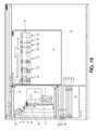
- FIG. 15 illustrates a representative test step display image that can be prepared by the dynamic diagnostic test generator for display on a display device according to an embodiment of the present disclosure.
- FIG. 16 is a flowchart illustrating a method or process for dynamically generating a diagnostic plan for a patient according to an embodiment of the present disclosure.
- a diagnostic test sequence can navigate a vehicle technician through a step-by-step test sequence based on a vehicle onboard computer trouble code or codes, or a vehicle operational symptom or symptoms.
- test step instructions and information can be displayed to the vehicle technician on a display screen panel.
- test step instructions and information can be displayed to the power tool technician on the display screen panel.
- the power tool can include, drills, saws, impact drivers, compressors, grinder, sander, joiner, cutter, wrench, hammer, blower, rotary tools, pneumatic tools, measuring tools, fluid electronic timers, routers, oscillating tools, cleaner and the like.
- the diagnostic test sequence can similarly navigate a medical technician or a doctor through a step-by-step test sequence based on a patient's symptoms.
- test step instructions and information can be displayed to the medical technician, such as a medical doctor on a display screen panel of a computing device, such as an IPadTM from AppleTM.
- a dynamic diagnostic plan generator can include a diagnostic test sequence optimizer that can arrange, or order, a sequence of diagnostic tests related to one or more symptoms to diagnose a failure mode of a vehicle, a power tool or a disease or disorder of a patient based at least in part on a failure mode or disease or disorder analysis.
- the sequence can be modified during test execution based on intermediate test results.
- the initial and iterative test sequence optimization, combined with the features below, can be referred to as “dynamic decision sequencing.”
- the diagnostic plan generator can also include a vehicle, a power tool or patient state tracker that can track the state of the vehicle/power tool/patient during and between diagnostic test procedures, and a test preparation step formatter that can format a test preparation step for display on a display device based at least in part on the vehicle/power tool/patient state.
- the diagnostic plan generator can further include a test procedure formatter that can format a sequence of test steps for display on a display device to provide instructions to a vehicle, power tool or medical technician for diagnosing the failure mode or disease or disorder.
- the diagnostic plan generator can also include an interactive diagnostic schematic generator that can illustrate a diagnostic test procedure, such as a wiring or anatomical diagram, for display on a display device.
- the dynamic diagnostic plan generator can include an information object producer that can create a data structure including information related to the diagnostic test procedures.
- the diagnostic plan generator can include a failure mode or disease or disorder identifier sender that can send a failure mode or disease or disorder identifier over a communication network to a central database, a historical data receiver that can receive historical data regarding the outcomes of previous diagnostic testing, and a failure mode or disease or disorder analyzer updater that can update the failure mode or disease or disorder analysis based on the historical, data.
- the diagnostic plan generator can include a failure mode or disease or disorder test authoring system that can be used by an expert vehicle, power tool or medical technician to create new failure mode or disease or disorder tests.
- FIG. 1 illustrates a vehicle test configuration that is compatible with the present inventive method and apparatus.
- a dynamic diagnostic plan generator 10 can include a personal computer 512 with a display 514 .
- the dynamic diagnostic plan generator 10 can be coupled to a vehicle 516 , including, for example, a vehicle onboard computer 518 .
- the dynamic diagnostic plan generator 10 can be coupled to the vehicle onboard computer 518 by way of a vehicle interface box 520 , as shown in FIG. 1 .
- the vehicle test configuration can further include electrical links 522 , 524 , such as wires, cables, data buses, a communication network or a wireless network.
- the dynamic diagnostic plan generator 10 can display diagnostic test procedure instructions to a vehicle or power tool technician to aid in performing vehicle or power tool diagnostics.
- the dynamic diagnostic plan generator 10 can also receive feedback from the vehicle 516 or the power tool (not shown).
- FIG. 2 illustrates a dynamic diagnostic plan generator 10 for use with, for example, a PC-based vehicle, power tool or patient diagnostic system to provide instructions for expert diagnostic procedures to allow a vehicle, power tool or a medical technician to identify the cause of a trouble code or fault or vehicle operational problem or a symptom at the component level.
- a related diagnostic method for use with a vehicle diagnostic system of this type is disclosed in U.S. Pat. No. 5,631,831, entitled “Diagnosis Method for Vehicle Systems,” to Bird, et al. dated May 20, 1997, the disclosure of which is hereby incorporated by reference in its entirety.
- the dynamic diagnostic plan generator 10 can include a processor 12 , a memory 14 , an input/output device 16 , a diagnostic test sequence optimizer 18 , a vehicle, power tool or patient state tracker 20 , a test preparation step formatter 22 , a test procedure formatter 24 , an interactive diagnostic schematic generator 26 , an information object producer 28 , a failure mode or disease or disorder identifier sender 30 , a historical data receiver 32 , a display device 34 , and a failure mode or disease or disorder test author 36 , all of which can be interconnected by a data link 38 .
- the processor 12 , the memory 14 , the input/output device 16 and the display device 34 can be part of a general computer, such as a personal computer (PC), a notebook, tablet, a UNIX workstation, a server, a mainframe computer, a personal digital assistant (PDA), wearable mounted device, or some combination of these.
- the processor 12 , the memory 14 and the input/output device 16 can be part of a specialized computing device, such as a vehicle diagnostic scan tool or a medical device such as a magnetic resonance imaging (MRI).
- the remaining components can include programming code, such as source code, object code or executable code, stored on a computer-readable medium that can be loaded into the memory 14 and processed by the processor 12 in order to perform the desired functions of the dynamic diagnostic plan generator 10 .
- the dynamic diagnostic plan generator 10 can be coupled to a communication network, which can include any viable combination of devices and systems capable of linking computer-based systems, such as the Internet; an intranet or extranet; a local area network (LAN); a wide area network (WAN); near-field communication (NFC), a direct cable connection; a private network; a public network; an Ethernet-based system; a token ring; a value-added network; a telephony-based system, including, for example, T1 or E1 devices; an Asynchronous Transfer Mode (ATM) network; a wired system; a wireless system; an optical system; a combination of any number of distributed processing networks or systems or the like.
- a communication network can include any viable combination of devices and systems capable of linking computer-based systems, such as the Internet; an intranet or extranet; a local area network (LAN); a wide area network (WAN); near-field communication (NFC), a direct cable connection; a private network; a public network; an Ethernet-based system; a token
- An embodiment of the dynamic diagnostic plan generator 10 can be coupled to the communication network by way of the local data link, which in various embodiments can incorporate any combination of devices—as well as any associated software or firmware—configured to couple processor-based systems, such as modems, network interface cards, serial buses, parallel buses, LAN or WAN interfaces, wireless or optical interfaces and the like, along with any associated transmission protocols, as may be desired or required by the design.
- processor-based systems such as modems, network interface cards, serial buses, parallel buses, LAN or WAN interfaces, wireless or optical interfaces and the like, along with any associated transmission protocols, as may be desired or required by the design.
- an embodiment of the dynamic diagnostic plan generator 10 can communicate information to the user and request user input by way of an interactive, menu-driven, visual display-based user interface, or graphical user interface (GUI).
- GUI graphical user interface
- the user interface can be executed, for example, on a personal computer (PC) with a mouse and keyboard, with which the user may interactively input information using direct manipulation of the GUI.
- Direct manipulation can include the use of a pointing device, such as a mouse or a stylus, to select from a variety of selectable fields, including selectable menus, drop-down menus, tabs, buttons, bullets, checkboxes, text boxes, and the like.
- various embodiments of the invention may incorporate any number of additional functional user interface schemes in place of this interface scheme, with or without the use of a mouse or buttons or keys, including for example, a trackball, a touch screen or a voice-activated system.
- the diagnostic test sequence optimizer 18 can select and arrange in order a group of diagnostic test procedures that are related to a symptom of a patient, a power tool, a vehicle operational problem or an onboard computer trouble code.
- An example of a diagnostic test sequence optimizer 18 that is compatible with the dynamic diagnostic plan generator 10 is disclosed in a copending U.S. patent application, entitled “Diagnostic Test Sequence Optimization Method and Apparatus,” filed concurrently herewith by Fountain, et al., the disclosure of which is hereby incorporated by reference in its entirety.
- the diagnostic test procedure sequence can be based, for example, on a diagnostic Failure Mode and Effects Analysis (FMEA) or on an author priority setting.
- FMEA or equivalently, a Failure Mode and Effects Criticality Analysis (FMECA)
- FMEA is a widely used tool in manufacturing industries, for example, the aerospace industry, the automotive industry, the heavy equipment industry and the digital electronics industry.
- FMEA has also been used in the health and power tool industries.
- a typical FMEA can include a list of failure modes or disease or disorder, causes and effects associated with each of the failure modes or diseases or disorders, a severity of each failure mode or disease or disorder, a risk or probability of the occurrence of each failure mode or disease or disorder, and additional information that can be useful in designing and manufacturing the associated product or component.
- FMEA can also be used to predict the likelihood of a disease or disorder of a patient's organs, such as a heart, due to the symptoms being assessed including increase blood pressure or cholesterol levels.
- the FMEA can include estimated probability information based on engineering analysis or statistical probability estimates based on empirical data from actual failures.
- each diagnostic test procedure can be an individual failure mode or disease or disorder test based on the failure modes or disease or disorder identified in the FMEA, and the FMEA information can be used to determine which of the diagnostic test procedures is most likely to identify the cause of the symptom.
- the diagnostic test procedure sequence can be based on multiple symptoms.
- the diagnostic test sequence optimizer 18 can evaluate two or more simultaneously occurring or intermittent symptoms in order to identify a possible common cause.
- the diagnostic test sequence optimizer 18 can dynamically reorder the test procedure sequence during test execution based on an interrelation of two or more symptoms.
- the diagnostic test sequence optimizer 18 may identify a common voltage source for two sensors that simultaneously have symptoms, and reorder the test sequence to verify the functionality of the common voltage source before performing failure mode or disease or disorder tests on the individual sensors, such as a heart or brain sensor.
- the test sequence can also be based on the comparative failure rates of the individual sensors and the common voltage source.
- the diagnostic test sequence optimizer 18 can dynamically reorder the test sequence to conduct a body scan of the heart, blood vessels and kidney before performing the individual tests on these components.
- the diagnostic test sequence optimizer 18 can dynamically reorder the test sequence during test execution based on intermediate results, for example, based on the results of a particular failure mode or disease or disorder test or a combination of failure mode or disease or disorder tests. For example, even though a particular failure mode or disease or disorder test does not result in a final diagnosis, the failure mode or disease or disorder test, alone or in combination with one or more other failure mode or disease or disorder tests, can validate the correct functionality of a component.
- the diagnostic test sequence optimizer 18 can dynamically reorder the test sequence, for example, to omit further failure mode or disease or disorder tests corresponding the validated component, or to move remaining failure mode or disease or disorder tests corresponding the validated component to a later position of lesser priority in the test sequence.
- the diagnostic test sequence optimizer 18 can dynamically reorder the test sequence during diagnostic test execution based on new information derived from a particular failure mode or disease or disorder test, although the failure mode or disease or disorder test does not result in a final diagnosis. For example, the discovery of an additional symptom during a particular failure mode or disease or disorder test can result in the diagnostic test sequence optimizer 18 modifying the test sequence based on the interrelation of the newly discovered symptom and the previously known symptom or symptoms. Thus, the diagnostic test sequence optimizer 18 can perform iterative, dynamic, run-time reevaluations during diagnostic test execution to continually modify or recreate the test sequence.
- Some existing diagnostic test systems include sequences of diagnostic test procedures that can performed on a patient, a vehicle or other product, such as power tool to determine a cause of a symptom. However, in some existing systems the sequence of the diagnostic tests is determined based solely on the priority assigned by an expert diagnostic author.
- An embodiment of the present invention can have the advantage that the diagnostic test procedure sequence can be optimized using statistical probability information based on historical outcomes of actual diagnostic testing in order to more accurately determine the efficacy of each of the diagnostic procedures.
- the diagnostic test procedure sequence can be customized to minimize or optimize the time required to resolve the problem, the cost required to resolve the problem, additional factors that can affect the problem resolution, a combination of these factors, or the like.
- the diagnostic test sequence optimizer 18 can perform an analysis of the comparative utility of each of the individual diagnostic procedures based on various factors that can affect problem resolution.
- the failure mode or disease or disorder analysis factors can include, but are not limited to, any of the following:
- the diagnostic test sequence optimizer 18 can assign a weight, or weighting, to each of the factors used in the failure mode or disease or disorder analysis. For example, a heavier weighting can be given to the time required to perform an individual diagnostic procedure versus the cost of performing the procedure and replacing an associated component. Conversely, the cost can be weighted heavier than the time required. Similarly, a greater weight can be assigned to the difficulty of performing the diagnostic procedure, for example, in relation to the expertise level of the vehicle, the power tool or medical technician. Greater weight may be on the availability of another medical technician such as a surgeon or a radiologist or an anesthesiologist.
- a greater weighting may be placed on the availability of a replacement component, including where the patient is in line for an organ transplant or whether a limb that fits the patient is available.
- a diagnostic procedure related to a component that is not available may be given a particularly low weighting.
- a heavier weighting can be assigned to a diagnostic procedure associated with a recommended maintenance procedure that is coming due, for example, based on the vehicle mileage or age of the power tool, and has not been performed on the subject vehicle or the power tool.
- the recommended maintenance procedure may be a mammogram for women over 40 years old.
- a heavy weighting can be placed on a diagnostic procedure related to a technical service bulletin, such as a recommended technical service bulletin issued by the vehicle or the power tool manufacturer. Further, a heavy weighting can be placed on a diagnostic procedure related to a bulletin, such as a recommended technical service bulletin issued by the vehicle or the power tool manufacturer or guidelines by National Institutes of Health.
- the weights can be partially determined based on user preferences.
- a user preference setting can be set by a diagnostic procedure author, by a service or medical center, by a vehicle, the power tool or medical technician, or by a combination thereof, and subsequently factored into the individual weightings of the factors.
- a service or medical center or a vehicle, the power tool or medical technician may prefer to minimize either time or cost, depending on the vehicle or the power tool type, urgency of medical attention needed, customer feedback or the like.
- a user input can be used by the diagnostic test sequence optimizer 18 in determining the weightings of certain critical factors in accordance with user preferences.
- the diagnostic test sequence optimizer 18 can receive a history of the vehicle or the power tool, for example, a maintenance or repair record kept with the vehicle or the power tool, at a service center, or by the manufacturer.
- the vehicle or power tool history can include information such as the mileage on the subject vehicle or age of the power tool, the specific configuration of the vehicle, a modification such as a technical service bulletin that has been performed on the vehicle or power tool, a vehicle or power tool maintenance record, a service center maintenance record associated with the specific vehicle or power tool or type of vehicle or power tool, or a manufacturer warranty record associated with the specific vehicle or power tool or type of vehicle or power tool or component having problems.
- the diagnostic test sequence optimizer 18 can receive a medical history of the patient, for example, a medical record at the medical center.
- the medical history can include information such as the age of the patient, previously diagnosed diseases, immunizations, current and past prescribed drugs, weight, height, family medical history or predispositions and the like.
- the diagnostic test sequence optimizer 18 can use the results of the failure mode or disease or disorder analysis, the vehicle or power tool history or patient medical history, user settings received by way of user input, a diagnostic FMEA or other input factors to order the diagnostic test procedures in a sequence.
- the sequence can be optimized in accordance with, for example, a priority input by a diagnostic test procedure author, a user preference input and any combination of the failure mode or disease or disorder analysis factors.
- the diagnostic test sequence optimizer 18 is highly and dynamically configurable to allow customization of the sequence optimization process.
- the vehicle or power tool state tracker 20 can track the state of the vehicle or power tool during and between individual diagnostic test procedures.
- the vehicle or power tool state tracker 20 can help to eliminate duplication of efforts during a diagnostic test sequence by keeping track of the current vehicle or power tool test configuration and providing test preparation steps to reconfigure the vehicle or power tool between individual diagnostic procedures without redundant steps.
- the vehicle or power tool state tracker 20 can track the current state of the vehicle or power tool by maintaining a current list of preconditions, or vehicle or power tool test configuration information.
- the patient state tracker 20 can track the state of the patient during and between individual diagnostic test procedures.
- the patient state tracker can help to eliminate duplication of efforts during a diagnostic test sequence by keeping track of the current testing and equipment being used, and providing test preparation steps to reconfigure the room or equipment being used or the patient (e.g. administering pain medication) between individual diagnostic procedures without redundant steps.
- the patient state tracker can track the current state of the patient by maintaining a current list of preconditions, or patient test information.
- the vehicle/power tool/patient state tracker 20 can determine a set of preconditions, or vehicle/power tool/patient test configuration requirements, necessary for an individual diagnostic test procedure. Preconditions and corresponding test preparation steps can be created, or authored, for example, by an expert diagnostics technician. Preconditions can also be formatted to be reusable in various diagnostic test procedures, which can save time during the authoring phase of diagnostic test procedures.
- the vehicle/power tool/patient state tracker 20 typically can determine the preconditions required for a subsequent diagnostic test procedure before the completion of a current diagnostic test procedure in order to prevent or minimize redundant efforts at the completion of the current diagnostic procedure and at the initiation of the subsequent diagnostic procedure.
- the vehicle/power tool/patient state tracker 20 can read the current state of the vehicle/power tool/patient, for example, from a memory register.
- the vehicle/power tool/patient state can be stored in a processor register, while in other embodiments the vehicle/power tool/patient state can be stored in a main memory register or in a memory register of a storage device associated with the dynamic diagnostic plan generator 10 .
- the vehicle/power tool/patient state tracker 20 can verify a current setting of the vehicle/power tool/patient state with regard to a specific precondition, or a group of current settings corresponding to a number of preconditions. If a precondition is required for the subsequent test procedure and the corresponding vehicle/power tool/patient state setting is currently not valid, the test preparation step formatter 22 can format a test preparation step for display on the display device 34 to instruct the vehicle, power tool or medical technician to set up the required precondition or vehicle/power tool/patient test configuration. As an example, FIG. 3 illustrates a representative test preparation step display screen 40 that can be prepared by the test preparation step formatter 22 . Similarly, FIG. 14 illustrates a representative medical test preparation step display screen 40 . Of course, if the precondition is required for the subsequent test procedure and the corresponding vehicle/power tool/patient state setting is currently valid, the test preparation step formatter 22 may elect not to format a test preparation step for display.
- the vehicle/power tool/patient state tracker 20 can receive feedback indicating when the precondition has been satisfied.
- the vehicle/power tool/patient state tracker 20 can receive a data signal from the vehicle onboard computer indicating that the precondition has been satisfied.
- the vehicle/power tool/patient state tracker 20 can receive a feedback signal from test equipment, such as a digital multimeter coupled to the vehicle or power tool or a blood pressure monitor coupled to the patient.
- the vehicle/power tool/patient state tracker 20 can receive user input from the vehicle, power tool or medical technician by way of the input/output device 16 indicating that the precondition has been satisfied, or that the vehicle, power tool or patient technician has complied with the test preparation step instructions.
- the vehicle/power tool/patient state tracker 20 can update the vehicle/power tool/patient state, for example, in a memory register, to reflect a valid setting corresponding to the precondition.
- the vehicle/power tool/patient state can be continually and dynamically updated to maintain a current and accurate vehicle/power tool/patient state that is available to the diagnostic system at any time in order to determine test preparation steps required to reconfigure the vehicle/power tool/patient between diagnostic procedures in a diagnostic test sequence.
- the test preparation step formatter 22 can format a test preparation step for display instructing the vehicle, power tool or medical technician to reverse, or undo, the vehicle/power tool/patient condition.
- the vehicle/power tool/patient state tracker 20 can receive feedback as described above and herein indicating that the condition has been reversed, and can update the vehicle/power tool/patient state, for example, in a memory register, to reflect an invalid setting corresponding to the condition, or precondition.
- the vehicle/power tool/patient state tracker 20 can maintain vehicle/power tool/patient state settings for any number of vehicle/power tool/patient preconditions associated with the diagnostic test procedures which can be configured to be readily available for use, or reuse, with any existing test procedure or with a new test procedure.
- preconditions can include, but are not limited to, any of the following:
- the dynamic diagnostic plan generator 10 can include a test procedure formatter 24 that can prepare the sequence of diagnostic test procedures for display on the display device.
- FIG. 4 illustrates a representative procedure display screen 42 that can be prepared by the test procedure formatter 24 .
- FIG. 15 also illustrates a representative procedure display that can be prepared by the test procedure formatter 24 .
- the test procedure formatter 24 can also prepare more detailed test preparation steps for display, for example, as shown in the detailed test procedure display screen 43 illustrated in FIG. 5 .
- the test procedure formatter 24 can further format navigational buttons 44 , such as the “Cancel,” “Back” and “Next” buttons shown in FIG. 5 , as well as additional navigational aids, such as the tabs 46 shown in FIG. 5 .
- An embodiment of the present invention communicates information to the user and requests user input by way of an interactive, menu-driven, visual display-based user interface.
- the dynamic diagnostic plan generator 10 can include input/output devices 16 , such as a mouse and keyboard, with which the user may interactively input information using direct manipulation of a graphical user interface (GUI).
- Direct manipulation includes using a pointing device, such as a mouse, to select from a variety of selectable fields, including selectable menus, tabs, buttons, bullets, checkboxes, text boxes, and the like.
- GUI graphical user interface
- pointing device such as a mouse
- select from a variety of selectable fields including selectable menus, tabs, buttons, bullets, checkboxes, text boxes, and the like.
- other embodiments of the invention may incorporate any number of additional functional user interface schemes in place of this interface scheme, with or without the use of a mouse or buttons or keys, including for example, a trackball, a touchscreen or a voice-activated system.
- test procedure formatter 24 can prepare detailed test step instructions, as shown in display image 43 , such as the representative test instruction 48 , “Set Multimeter select knob to DC Volts,” shown in FIG. 6 .
- the test procedure formatter 24 can also provide detailed test setup instructions, for example, the representative test lead connections instructions 50 .
- the test procedure formatter 24 can prepare test equipment display images, such as the multimeter display 52 shown in FIG. 6 .
- the dynamic diagnostic plan generator 10 can further receive dynamic input data, for example, a digital multimeter or blood pressure monitor input for real-time display.
- the step instructions may also be formatted for use with power tools.
- test procedure formatter 24 and the test preparation step formatter 22 can cooperate to prepare combined display windows 50 , such as the test step display image 42 , the test preparation step display image 40 and the diagnostic procedure display image 43 shown in FIG. 6 , which can be displayed simultaneously on the display device 34 .
- test procedure formatter 24 can prepare additional informational display images, such as a “description” display image (not shown) or an “information” display image 56 , as shown in FIG. 7 .
- the test procedure formatter 24 can prepare a “results” display image 58 as shown in FIG. 8 .
- the test procedure formatter 24 can provide specific instructions for reconfiguring the vehicle/power tool/patient after a test procedure or a diagnostic test sequence has been completed, such as the reconfiguration instructions 60 shown in FIG. 8 .
- an embodiment of the diagnostic plan generator 10 can provide the vehicle, power tool or medical technician with the option of storing the results of a diagnostic procedure in a memory 14 , for example, with a “Log Test” button 62 .
- the interactive diagnostic schematic generator 26 can generate a diagnostic schematic, such as the representative diagnostic schematic 64 illustrated in FIG. 9 .
- An example of an interactive diagnostic schematic generator 26 that is compatible with the dynamic diagnostic plan generator 10 is disclosed in a copending U.S. patent application, entitled “Interactive Schematic Generating Method and Apparatus for a Vehicle Diagnostic Procedure,” filed concurrently herewith by Fountain, et al., the disclosure of which is hereby incorporated by reference in its entirety.
- the interactive diagnostic schematic 64 can illustrate any number of vehicle components 66 or patient or power tool components (not shown).
- vehicle components 66 in FIG. 9 could represent a bank angle sensor, a throttle position sensor, a cam position sensor and an electronic control module, or any additional vehicle components 66 related to a diagnostic procedure.
- patient components may include the heart, brain, kidneys and the like while examples of power tool components may include power buttons, drill speed switch, motor windings, batteries and the like.
- the interactive diagnostic schematic generator 26 can read a schematic data file associated with a diagnostic test procedure, for example, a wiring or anatomical diagram data file.
- the interactive diagnostic schematic generator 26 can read a data file from a main memory or from a peripheral memory device associated with the processor 12 .
- the schematic data file can be stored in a scalable vector graphics (SVG) file format, which is an XML-based markup language for describing two-dimensional vector graphics, both static and animated (i.e., either declarative or scripted).
- SVG scalable vector graphics
- the schematic data file can be stored as a text file.
- SVG formatting can allow various types of graphic objects, for example, vector graphic shapes consisting of straight lines and curves and the areas bounded by them, raster graphics images or text. SVG formatting further can allow graphical objects to be grouped, styled, transformed and composited into previously rendered objects. SVG formatting can also permit nested transformations, clipping paths, alpha masks, filter effects, template objects and extensibility. In addition, SVG formatting can enhance searchability and accessibility of the graphics.
- the interactive diagnostic schematic 64 can be dynamic and interactive.
- a document object model (DOM) in SVG formatting can allow straightforward and efficient animation of graphics by way of script languages.
- the SVG graphics file format is also compatible with popular communications network standards, such as World Wide Web standards on the Internet. Additionally, SVG images can be stored using compression techniques.
- SVG data files can be prepared for display on a display device 34 by any number of commercially available SVG viewers, such as the Adobe SVG Viewer, produced by Adobe Systems Incorporated of San Jose, Calif., or the Corel SVG Viewer, produced by the Corel Corporation of Ottawa, Canada.
- SVG viewers such as the Adobe SVG Viewer, produced by Adobe Systems Incorporated of San Jose, Calif., or the Corel SVG Viewer, produced by the Corel Corporation of Ottawa, Canada.
- the interactive diagnostic schematic generator 26 can modify the schematic data file to indicate a test subject in the schematic.
- the interactive diagnostic schematic generator 26 can alter the color of the vehicle component 66 , electrical connector 68 , wire 70 , or the like, and can highlight the test subject by surrounding the test subject with a highlighting color to make the test subject stand out from the background and the remaining items in the schematic. This can also be done with patient components such as brain, heart, kidney and the like or power tool components such as power buttons, drill speed switch, motor windings, batteries and the like.
- the interactive diagnostic schematic generator 26 can shade the test subject, fade the color of the test subject, gray out the test subject, or animate the test subject.
- the interactive diagnostic schematic generator 26 can animate the test subject by making the vehicle component 66 , electrical connector 68 , wire 70 , or the like, blink or flash in the schematic 64 when displayed on a display device 34 . This can be accomplished, for example, by adding executable code in a scripting language to the schematic data file. This can also be done with patient components such as brain, heart, kidney and the like or power tool components such as power buttons, drill speed switch, motor windings, batteries and the like.
- the interactive diagnostic schematic generator 26 can animate the test subject by adding motion to the schematic 64 , for example, demonstrating the connection or disconnection of an electrical connector 68 or a neural connection between neurons in the brain.
- the interactive diagnostic schematic generator 26 can also zoom in on a specific component 66 , for example, when a user clicks on the component 66 using a pointing device, such as a mouse or use fingers motions on the touch screen display.
- the interactive diagnostic schematic generator 26 can add properties to the component 66 , for example, a part number, inventory information regarding the component, a link to a help file, or the like.
- the interactive diagnostic schematic generator 26 can illustrate a location on the schematic 64 where a test equipment connection is required.
- the interactive diagnostic schematic generator 26 can highlight or otherwise locate a location or multiple locations where electrical connectors, pins, clamps, or the like associated with test equipment are to be connected to the vehicle component 66 or electrical connector 68 .
- the interactive diagnostic schematic generator 26 can further illustrate required test equipment, such as a digital multimeter, in the schematic 64 .
- the test equipment locations where pads for an EKG machine needs to be located to measure the heart can be highlighted and illustrate the required test equipment, such an EKG machine.
- the test lead locations to test battery connections on a drill can be highlighted and illustrate the required test component, such as a volt meter. This can aid a vehicle, power tool or medical technician to quickly and efficiently connect test equipment for a diagnostic test procedure.
- the diagnostic schematic generator 26 can format the originally stored schematic or a modified schematic for display on the display device 34 .
- the diagnostic schematic generator 26 can include an SVG viewer or cooperate with an SVG viewer to display the diagnostic schematic generator 26 .
- the interactive diagnostic schematic generator 26 can receive feedback, for example, by direct manipulation such as a user selecting a portion of the schematic using a mouse, finger or the equivalent. For example, a user can “click” on a wire, a component, or another test subject within a schematic currently displayed on the screen, and the feedback receiver 36 can uniquely identify the selected test subject.
- the interactive diagnostic schematic generator 26 can, for example, remove or discontinue the indication of the test subject in the schematic. That is to say, the test subject indicator 30 can remove or discontinue the highlighting, fading, graying out or animation of the test subject in the diagnostic schematic 10 .
- online help can be accessed by way of direct manipulation of displayed objects in the schematic.
- the interactive diagnostic schematic generator 26 can mark the test subject to indicate that a diagnostic procedure, test step or other action has been performed on the test subject.
- the schematic generator 26 can use highlighting, shading, fading, graying out or animation of the test subject to indicate that the action has been performed.
- the marking style used to mark the test subject to indicate that the action has been performed can be visually distinct from the indicating style used to indicate the test subject on which an action is required.
- the information object producer 28 can create a diagnostic data structure, or information object, based on information related to the diagnostic test procedures.
- the information object can include the diagnostic test procedure instructions, a list of possible causes of the symptom, the vehicle history, the power tool history, the patient history, the current state of the vehicle/power tool/patient, a diagnostic schematic, a Failure Mode and Effects Analysis (FMEA) compiled by the vehicle manufacturer or a component manufacturer, or the like.
- FMEA Failure Mode and Effects Analysis
- the information object can include, but is not limited to, information such as the following:
- the failure mode or disease or disorder identifier sender 30 can send a failure mode or disease or disorder identifier (I.D.) indicating the failure mode or disease or disorder over a communication network to a central database.
- a failure mode or disease or disorder identifier I.D.
- the failure mode or disease or disorder identifier can be sent to a service or medical center database, a manufacturer warranty database, or the like, over the Internet, an intranet, or a wireless network.
- the failure mode or disease or disorder identifier can include additional information associated with the diagnostic case, such as observed symptoms, diagnostic trouble codes (DTCs), a vehicle identification, a vehicle or power tool history, age of the patient, a vehicle/power tool/patient state as measured and observed, systematic data readings, specific parameters relevant to the optimization process (for example, any of the factors enumerated above), and the final diagnostic conclusion.
- the final diagnostic conclusion can include a failure-mode identifier or a no-failure-mode-identified diagnosis. In this manner, the failure mode or disease or disorder occurrences can automatically be gathered in a central database in order to allow analysis of failure mode or disease or disorder occurrences to continually or dynamically update the statistical failure mode or disease or disorder information.
- the historical data receiver 32 can receive failure mode or disease or disorder historical data over a communication network from a central database, for example, the results of a Failure Mode and Effects Analysis performed by the vehicle or power tool manufacturer using automatically-updated information from a region, a country, or an entire fleet of vehicles, line of power tools or from a prosthetic limb manufacturer.
- the historical failure mode or disease or disorder data can be used by the diagnostic test sequence optimizer 18 to order the diagnostic test procedures in an optimal sequence based on the latest updated information available.
- the diagnostic test sequence compiled by the dynamic diagnostic plan generator 10 can change over time in a dynamic manner, based on actual failure mode or disease or disorder occurrences.
- the failure mode or disease or disorder test author 36 can provide a vehicle/power tool/patient diagnostic system authoring capability to facilitate the creation of failure mode or disease or disorder test procedures by an individual who is an expert in vehicle/power tool/patient diagnostics but is not necessarily knowledgeable concerning a computer programming language.
- the failure mode or disease or disorder test author 36 can accelerate development and reduce errors in diagnostic software by eliminating the need for a computer programmer to code the process as explained by an expert in vehicle diagnostics.
- the failure mode or disease or disorder test author 36 can be particularly useful to an original equipment manufacturer for developing electronic diagnostic sequences.
- a representative failure mode or disease or disorder authoring display image is shown in FIG. 10 , comprising a graphical user interface (GUI) work environment for use by an expert author to develop a test structure for a failure mode or disease or disorder test.
- the work environment can include a test structure display image 74 , a FMEA details editor display image 76 and a symptom properties display image 78 .
- the failure mode or disease or disorder test work environment can allow a diagnostics author to interactively create a failure mode or disease or disorder test that can be used in a diagnostic test sequence, including associated details or properties.
- the test structure display image 74 can include a hierarchical breakdown, for example, by vehicle make 80 , vehicle model 82 , symptom type 84 , vehicle component 86 , and symptom 88 .
- Each symptom 88 can be associated with a group of failure mode or disease or disorder tests 90 and preconditions 92 .
- the symptom properties display image 78 can display properties or information stored by the dynamic diagnostic plan generator 10 regarding a specific symptom.
- symptom properties can include a name or nametag 94 corresponding to the symptom, a code 96 corresponding to the symptom, a component identifier 98 and a symptom type identifier 100 .
- the symptom properties can further include additional information, such as an introduction identifier 102 , a priority 104 , a key word 106 , a description 108 , and one or more flags 110 associated with the symptom.
- the FMEA details editor display image 76 can display FMEA information stored by the dynamic diagnostic plan generator 10 , such as statistical probability factors based on actual failure mode or disease or disorder occurrences corresponding to the symptom.
- the FMEA information can include a nametag field 112 , a name field 114 , and a listing of records 116 associated with individual failure mode or disease or disorder tests.
- Each of the records can include, for example, a name tag 118 , a component 120 associated with the failure mode or disease or disorder, a test identifier 122 , an author rank assigning an estimated probability to the failure mode or disease or disorder test 124 , a cost 126 associated with performing the failure mode or disease or disorder test, a risk 128 associated with the failure mode or disease or disorder test, a difficulty factor 130 , or other information associated with the failure mode or disease or disorder test.
- an expert diagnostic author can use an authoring work environment 72 to create a new failure mode or disease or disorder test.
- the author can define the system to which the failure mode or disease or disorder corresponds, for example, by specifying the vehicle make 80 and model 82 or race and age of the patient.
- the author can also specify the symptom type 84 or category, for example, a vehicle-defined symptom such as a diagnostic trouble code (DTC), a patient defined symptom such as high blood pressure or a user-defined symptom.
- DTC diagnostic trouble code
- the author can further define a pertinent system or unit 86 and a specific symptom 88 to be diagnosed.
- the author can then define an introduction associated with the symptom to provide information about the symptom to the vehicle or medical technician.
- the introduction can include, for example, a failure mode or disease or disorder description, circuit diagrams, tips, or the like.
- the author can define multiple failure modes or disease or disorder 90 associated with the symptom.
- the author can create a reusable failure mode or disease or disorder test for each failure mode or disease or disorder and associate preconditions 92 required for each failure mode or disease or disorder test.
- Preconditions 92 can be procedures that must be completed prior to the performance of the failure mode or disease or disorder test, as previously discussed. Once created, a precondition 92 can be reused for additional failure mode or disease or disorder tests.
- the author can further specify a sequence associated with the preconditions for a failure mode or disease or disorder test, an indication as to whether the precondition must be removed or reversed after the failure mode or disease or disorder test, and associated procedures for removing or reversing preconditions after the failure mode or disease or disorder test.
- FIG. 11 illustrates a representative display image of a failure mode or disease or disorder test creation display image 132 that an expert author can access, for example, by double-clicking on one of the failure modes or diseases or disorders 90 in the test structure display image 74 shown in FIG. 10 .
- the failure mode or disease or disorder test creation display image 132 can include, for example, nodes 134 corresponding to diagnostic test procedure steps.
- the nodes 134 can be connected by decision branches 136 having round bulbs 138 , which represent logical expressions associated with the test nodes 134 or decision branches 136 .
- the failure mode or disease or disorder test creation display image 132 can further include a form 140 associated with a highlighted node 142 .
- failure mode or disease or disorder test creation display image 132 can provide form fields 144 for entering information about the form 140 , node fields 146 for entering information about the highlighted node 142 , and a branches field 148 for entering information about the branches 136 and logical expression bulbs 138 associated with the highlighted node 142 .
- the dynamic diagnostic plan generator 10 can perform a reverse failure analysis that can identify symptoms, or operational problems, of a vehicle/power tool/patient and correlate each symptom to a specific failure mode of a vehicle/power tool disease or disorder of a patient component that is the cause of the symptom.
- a reverse failure analysis for use with a vehicle diagnostic system is disclosed in a copending U.S. patent application, entitled “Reverse Failure Analysis Method and Apparatus for Diagnostic Testing,” filed concurrently herewith by Fountain, et al. the disclosure of which is incorporated by reference in its entirety.
- the dynamic diagnostic plan generator 10 can gather and organize information corresponding to an optimized diagnostic test plan from a diverse set of information sources and generate an information object.
- the information object can be organized, for example, in a sequence or data structure that corresponds to the optimized diagnostic test plan.
- the information object can be interpreted as a dynamically-created manual that has been customized in accordance with a specific optimized diagnostic test plan, and which a user can access during execution of the corresponding diagnostic test plan, or at any time during diagnosis and repair, or treatment.
- An example of a method for generating an information object for use with a vehicle diagnostic system is disclosed in a copending U.S. patent application, entitled “Information Object Creation Based on an Optimized Test Procedure Method and Apparatus,” filed concurrently herewith by Fountain, et al., the disclosure of which is incorporated by reference in its entirety.
- FIG. 12 illustrates a method or process for dynamically generating a diagnostic plan.
- the process can begin by proceeding to step 150 , “Optimize Diagnostic Test Sequence,” in which a sequence of diagnostic test procedures can be optimally ordered based on a failure mode or disease or disorder analysis, a vehicle or power tool history, a current vehicle or power tool state, user preferences, or other factors that can affect the resolution of a symptom or an operational problem of a vehicle or power tool, as described above.
- the diagnostic test sequence optimization can take into account information from a Failure Mode Effects Analysis (FMEA), as described above.
- FMEA Failure Mode Effects Analysis
- step 152 “Track Vehicle State,” a current state of the vehicle or power tool can be read from a memory and updated, as explained above. Then, based on the diagnostic test sequence and vehicle or power tool state, in step 154 , “Format Test Prep Step,” a test preparation step or steps can be formatted for display on a display device to provide instructions for a vehicle or power tool technician, as described above.
- an interactive diagnostic schematic can be generated in step 156 , “Generate Interactive Diagnostic Schematic.”
- the interactive diagnostic schematic can illustrate a diagnostic test procedure when displayed on a display device.
- step 158 “Produce Information Object,” an information object can be created as a data structure containing information regarding the interactive diagnostic procedures as a supplemental resource for the vehicle or power tool technician.
- step 160 “Format Diagnostic Test Procedure,” a diagnostic test procedure can be formatted for display on a display device to provide instructions for the vehicle or power tool technician, as described above.
- “Receive Input,” input can be received indicating that the test procedures have been performed and that the associated failure mode has been verified or eliminated, as described above.
- step 164 “Send Failure Mode,” a failure mode identifier can be sent over a communication network to a central database, for example, at a service center or a manufacturer, as described above.
- a central database for example, at a service center or a manufacturer, as described above.
- step 166 “Receive Historical Data,” historical data regarding actual failure mode occurrences can be received, for example, from a service center, regional database, a country database, a fleet database, or the like. Consequently, in step 168 , “Update Failure Mode Analysis,” failure mode frequency or rate information can be updated with the historical data for use in subsequent diagnostic test sequence optimizations.
- FIG. 13 illustrates a patient test configuration in accordance with an embodiment of the present disclosure.
- the dynamic diagnostic plan generator 10 can include a personal computer 512 with a display 514 .
- the dynamic diagnostic plan generator 10 can be coupled to a patient 414 .
- the patient 414 may be monitored for various symptoms that may be related to various illnesses.
- the dynamic diagnostic plan generator 10 can be coupled to the patient 414 by way of an interface 520 , as shown in FIG. 13 .
- the patient test configuration can further include electrical link 524 , such as wires, cables, data buses, a communication network or a wireless communication link or network.
- the dynamic diagnostic plan generator 10 can display diagnostic test procedure instructions to a technician to aid in performing diagnostics of the patient 414 .
- the dynamic diagnostic plan generator 10 can also receive feedback from the patient 414 .
- the patient 414 may be coupled to an infrared finger cuff 404 to measure a saturated percentage of oxygen in the blood.
- the patient 414 may be coupled to an electrocardiograph 406 that may illustrate the QRST waves of the heart.
- the patient 414 may be coupled to a blood pressure transducer 408 that may measure the blood pressure.
- the patient 414 may be coupled to an adhesive pad containing a thermoelectric transducer 410 that may measure the body temperature.
- the patient 414 may be coupled to a thoracic transducer belt 412 that may measure airway respiratory rate. Additional monitoring devices may be coupled to the patient 414 to observe and collect various symptoms. These monitoring devices 404 - 412 may measure various symptoms of the patient 414 which are conveyed to the dynamic plan generator 10 .
- the dynamic diagnostic plan generator 10 can verify a current condition of the patient 414 with regard to a specific precondition, or a group of current conditions corresponding to a number of preconditions. If a precondition is required for the subsequent test procedure and the corresponding patient 414 condition is currently not valid, the test preparation step formatter 22 can format a test preparation step for display on the display device 34 to instruct the medical technician to set up the required precondition or patient test configuration.
- FIG. 14 illustrates a representative test preparation step display screen 40 that can be prepared by the test preparation step formatter 22 to instruct the medical technician on the steps for coupling the patient 414 to an electrocardiograph 406 .
- the pulse of the patient 414 may be recorded, the body temperature of the patient may be recorded, the electrocardiogram may be performed, a complete blood count may be initiated and the lung condition of the patient 414 may be evaluated.
- the QRST waves of the heart of the patient 414 may be read.
- the test preparation step formatter 22 may elect not to format a test preparation step for display.
- the dynamic diagnostic plan generator 10 can receive feedback indicating when the precondition has been satisfied.
- the dynamic diagnostic plan generator 10 can receive a data signal from the interface 520 indicating that the precondition has been satisfied.
- the dynamic diagnostic plan generator 10 can receive a feedback signal from test equipment, such as the electrocardiograph 406 coupled to the patient 414 .
- the dynamic diagnostic plan generator 10 can receive user input from the medical technician by way of the input/output device 16 indicating that the precondition has been satisfied, or that the medical technician has complied with the test preparation step instructions.
- the dynamic diagnostic plan generator 10 can update the patient condition, for example, in a memory register, to reflect a valid setting corresponding to the precondition.
- the patient condition can be continually updated to maintain a current and accurate patient condition that is available to the diagnostic system at any time in order to determine test preparation steps required to prepare the patient 414 between diagnostic procedures in a diagnostic test sequence.
- the test preparation step formatter 22 can format a test preparation step for display instructing the medical technician to reverse, or undo, the patient condition.
- the dynamic diagnostic plan generator 10 can receive feedback as described above indicating that the condition has been reversed, and can update the patient condition, for example, in a memory register, to reflect an invalid setting corresponding to the condition, or precondition.
- the dynamic diagnostic plan generator 10 can maintain patient condition for any number of preconditions associated with the diagnostic test procedures which can be configured to be readily available for use, or reuse, with any existing test procedure or with a new test procedure.
- preconditions can include, but are not limited to, any of the following:
- FIG. 16 illustrates a method or process for dynamically generating a diagnostic plan according to another embodiment of the present disclosure.
- the process can begin by proceeding to step 250 , “Optimize Diagnostic Test Sequence,” in which a sequence of diagnostic test procedures can be optimally ordered based on a failure mode or disease or disorder analysis, a patient's history, a current patient state, user preferences, or other factors that can affect the resolution of a symptom or an illness of a patient.
- the diagnostic test sequence optimization can take into account information from a Failure Mode Effects Analysis (FMEA), as described above.
- FMEA Failure Mode Effects Analysis
- the sequence can be optimized in accordance with, for example, a priority input by a diagnostic test procedure author, a user preference input and any combination of the failure mode or disease or disorder analysis factors.
- the diagnostic test sequence optimizer 18 (shown in FIG. 2 ) is highly configurable to allow customization of the sequence optimization process.
- the historical failure mode or disease or disorder data can be used by the diagnostic test sequence optimizer 18 to order the diagnostic test procedures in an optimal sequence based on the latest updated information available.
- the diagnostic test sequence compiled by the dynamic diagnostic plan generator 10 (shown in FIG. 2 ) can change over time in a dynamic manner, based on actual failure mode or disease or disorder occurrences.
- step 252 “Track Patient State,” a current state of the patient can be read from a memory and updated.
- the patient's record may be inputted by a user.
- the patient's record may be collected from a database storing the patient records.
- “Format Test Prep Step” a test preparation step or steps can be formatted for display on a display device to provide instructions for a technician, as described above.
- an interactive diagnostic schematic can be generated in step 256 , “Generate Interactive Diagnostic Schematic.”
- the interactive diagnostic schematic can illustrate a diagnostic test procedure when displayed on a display device.
- the interactive diagnostic schematic 64 (shown in FIG. 9 ) can illustrate any number of patient organs.
- the organs could represent a heart, a lung, a liver, a kidney, a stomach, a colon, a brain, and a respiratory system, or any additional organs related to a diagnostic procedure.
- Step 258 “Produce Information Object,” an information object can be created as a data structure containing information regarding the interactive diagnostic procedures as a supplemental resource for the diagnostic technician or doctor diagnosing illnesses.
- step 260 “Format Diagnostic Test Procedure,” a diagnostic test procedure can be formatted for display on a display device to provide instructions for the diagnostic technician or doctor, as described above.
- “Receive Input,” input can be received indicating that the test procedures have been performed and that the associated failure mode or disease or disorder has been verified or eliminated, as described above.
- an illness identifier can be sent over a communication network to a central database, for example, at a medical center or a central database.
- the illness identifier can be sent to a central database for storing.
- “Receive Historical Data” historical data regarding actual illness occurrences can be received, for example, from a medical center, regional database, a country database, a medical database, or the like.
- “Update Failure Mode or Disease or Disorder Analysis” failure mode or disease or disorder frequency or rate information can be updated with the historical data (e.g., illness frequency or rate) for use in subsequent diagnostic test sequence optimizations.
- FIGS. 1-10 Some of the figures are block diagrams and flowcharts of methods, apparatuses and computer program products according to various embodiments of the present invention. It will be understood that each block or step of the block diagram, flowchart and control flow illustrations, and combinations of blocks in the block diagram, flowchart and control flow illustrations, can be implemented by computer program instructions or other means. Although computer program instructions are discussed, an apparatus according to the present invention can include other means, such as hardware or some combination of hardware and software, including one or more processors or controllers, for performing the disclosed functions.
- FIG. 2 depicts the apparatus of one embodiment including several of the key components of a general-purpose computer by which an embodiment of the present invention may be implemented.
- a computer can include many more components than those shown in FIG. 2 . However, it is not necessary that all of these generally conventional components be shown in order to disclose an illustrative embodiment for practicing the invention.
- the general-purpose computer can include a processing unit 12 and a system memory 14 , which may include random access memory (RAM) and read-only memory (ROM).
- RAM random access memory
- ROM read-only memory
- the computer also may include nonvolatile storage memory, such as a hard disk drive, where additional data can be stored.
- An embodiment of the present invention can also include one or more input or output devices 16 , such as a mouse, keyboard, monitor, and the like.
- a display can be provided for viewing text and graphical data, as well as a user interface to allow a user to request specific operations.
- an embodiment of the present invention may be connected to one or more remote computers via a network interface. The connection may be over a local area network (LAN) wide area network (WAN), and can include all of the necessary circuitry for such a connection.
- LAN local area network
- WAN wide area network
- computer program instructions may be loaded onto the computer or other general purpose programmable machine to produce a specialized machine, such that the instructions that execute on the computer or other programmable machine create means for implementing the functions specified in the block diagrams, schematic diagrams or flowcharts.
- Such computer program instructions may also be stored in a computer-readable medium that when loaded into a computer or other programmable machine can direct the machine to function in a particular manner, such that the instructions stored in the computer-readable medium produce an article of manufacture including instruction means that implement the function specified in the block diagrams, schematic diagrams or flowcharts.
- the computer program instructions may be loaded into a computer or other programmable machine to cause a series of operational steps to be performed by the computer or other programmable machine to produce a computer-implemented process, such that the instructions that execute on the computer or other programmable machine provide steps for implementing the functions specified in the block diagram, schematic diagram, flowchart block or step.
- blocks or steps of the block diagram, flowchart or control flow illustrations support combinations of means for performing the specified functions, combinations of steps for performing the specified functions and program instruction means for performing the specified functions. It will also be understood that each block or step of the block diagrams, schematic diagrams or flowcharts, as well as combinations of blocks or steps, can be implemented by special purpose hardware-based computer systems, or combinations of special purpose hardware and computer instructions, that perform the specified functions or steps.
- a data input software tool of a search engine application can be a representative means for receiving a query including one or more search terms.
- Similar software tools of applications, or implementations of embodiments of the present invention can be means for performing the specified functions.
- an embodiment of the present invention may include computer software for interfacing a processing element with a user-controlled input device, such as a mouse, keyboard, touchscreen display, scanner, or the like.
- an output of an embodiment of the present invention may include, for example, a combination of display software, video card hardware, and display hardware.
- a processing element may include, for example, a controller or microprocessor, such as a central processing unit (CPU), arithmetic logic unit (ALU), or control unit.
Landscapes
- Engineering & Computer Science (AREA)
- Physics & Mathematics (AREA)
- Health & Medical Sciences (AREA)
- Biomedical Technology (AREA)
- Data Mining & Analysis (AREA)
- Theoretical Computer Science (AREA)
- Medical Informatics (AREA)
- General Physics & Mathematics (AREA)
- Public Health (AREA)
- Probability & Statistics with Applications (AREA)
- Mathematical Analysis (AREA)
- General Health & Medical Sciences (AREA)
- Epidemiology (AREA)
- Algebra (AREA)
- Artificial Intelligence (AREA)
- Computational Mathematics (AREA)
- Evolutionary Computation (AREA)
- Pathology (AREA)
- Primary Health Care (AREA)
- Mathematical Optimization (AREA)
- Pure & Applied Mathematics (AREA)
- Computing Systems (AREA)
- General Engineering & Computer Science (AREA)
- Mathematical Physics (AREA)
- Software Systems (AREA)
- Databases & Information Systems (AREA)
- Medical Treatment And Welfare Office Work (AREA)
Abstract
Description
-
- an estimated time required to perform a diagnostic test
- the difficulty of performing the diagnostic test
- an estimated time required to remove and replace a component (heart with an artificial heart) associated with the diagnostic test
- the difficulty of removing and replacing the component
- the level of expertise of a vehicle or power tool service technician or medical technician (including medical doctors) performing the diagnostic procedure
- the availability of a replacement component (including organ transplants, skin grafts, implants, prosthetics, and the like)
- the estimated cost or the actual cost of the component
- the estimated or actual cost of labor
- empirical data regarding the probability that a failure mode or disease or disorder associated with the individual diagnostic procedure exists given the existence of a specified symptom (e.g., FMEA data)
- an estimate of the probability that the failure mode or disease or disorder exists given the existence of the symptom
- a frequency or rate of the failure mode or disease or disorder associated with the diagnostic procedure
- the mileage of the subject vehicle
- the number of rotation of saw blade
- breaking condition of the power tool
- usage cycle of the power tool
- the year of the subject vehicle
- age of the patient
- age of the power tool
- safety alerts of the replacement medical component
- safety alerts of the replacement power tool component such as drill bit, saw blade, and so forth
- previous surgery on that component (previous heart surgery)
- time between other surgery
- other existing medical conditions
- availability of other medical technicians, such as an radiologist or anesthesiologist
- the specific configuration of the vehicle or the power tool or a modification that has been performed on the vehicle or the power tool
- the vehicle or the power tool maintenance record
- the patient's medical history
- a service center maintenance record regarding the vehicle or the power tool or associated vehicles or the power tools
- a manufacturer warranty record associated with the specific vehicle or the power tool or a type of vehicle or the power tool
- a manufacturer warranty record associated with the specific component
- a recommended maintenance schedule, such as a manufacturer recommended maintenance schedule, or
- a technical service bulletin issued by the vehicle manufacturer.
-
- blood pressure level
- heart rate
- pain level
- heart rate monitor
- IV line
- preparation of surgical area on the patient
- an ignition switch position
- a light switch position
- an engine run condition
- a throttle position
- sensing system position
- detection system connection condition
- kick-back system connection condition
- a braking system condition
- an engine speed
- drill bit rotation speed
- saw blade rotation speed
- a vehicle speed
- a test equipment connection
- a vehicle or power tool electrical connection condition
- an ambient air temperature
- an engine inlet temperature
- an engine lubricant pressure
- engine lubricant temperature
- an engine lubricant level
- an engine coolant temperature
- an engine coolant specific gravity
- an engine exhaust gas temperature
- an engine exhaust gas content
- a transmission setting
- a brake pedal position
- a parking brake position
- a brake fluid pressure
- a fuel level
- a fuel supply pressure
- a battery voltage
- a battery charging system voltage
- a battery charging system current
- an ignition voltage
- an ignition current
- an engine cylinder compression
- a vehicle or power tool configuration, or
- a vehicle or power tool modification.
-
- an estimated time required to perform the diagnostic test procedures
- a difficulty level of performing the diagnostic test procedures an estimated time required to remove and replace a component associated with the diagnostic test procedures
- a difficulty level of removing and replacing a component
- availability of other technicians such as a radiologist
- an availability of a replacement component
- wait time until a donor is available
- an estimated cost of the component
- an actual cost of the component
- an estimated cost of performing the diagnostic test procedures
- empirical data regarding the probability that a failure mode or disease or disorder exists given the existence of the symptom
- an estimate of the probability that a failure mode or disease or disorder exists given the existence of the symptom
- a frequency or rate of the failure mode or disease or disorder
- a vehicle mileage
- age of the patient or power tool
- a vehicle or power tool configuration
- a vehicle or power tool modification
- previous surgery or amputation
- a vehicle or power tool maintenance record
- a service center maintenance record
- medical center medical records
- a manufacturer warranty record
- the recommended maintenance schedule for the vehicle, or power tool, or
- a technical service bulletin.
-
- time since last meal
- time since last drink
- body temperature
- seated position
- standing position
- heart rate
- a test equipment connection
- breath volume
- an ambient air temperature
- pace on a treadmill test
- oxygenation level of blood
- reflex response
- consciousness
- allergies
- phobias
- medical history
- prior surgeries
- current medications, or
- time of day.
Claims (20)
Priority Applications (1)
| Application Number | Priority Date | Filing Date | Title |
|---|---|---|---|
| US13/785,729 US9081883B2 (en) | 2006-06-14 | 2013-03-05 | Dynamic decision sequencing method and apparatus for optimizing a diagnostic test plan |
Applications Claiming Priority (2)
| Application Number | Priority Date | Filing Date | Title |
|---|---|---|---|
| US11/452,250 US8423226B2 (en) | 2006-06-14 | 2006-06-14 | Dynamic decision sequencing method and apparatus for optimizing a diagnostic test plan |
| US13/785,729 US9081883B2 (en) | 2006-06-14 | 2013-03-05 | Dynamic decision sequencing method and apparatus for optimizing a diagnostic test plan |
Related Parent Applications (1)
| Application Number | Title | Priority Date | Filing Date |
|---|---|---|---|
| US11/452,250 Continuation-In-Part US8423226B2 (en) | 2006-06-14 | 2006-06-14 | Dynamic decision sequencing method and apparatus for optimizing a diagnostic test plan |
Publications (2)
| Publication Number | Publication Date |
|---|---|
| US20130185093A1 US20130185093A1 (en) | 2013-07-18 |
| US9081883B2 true US9081883B2 (en) | 2015-07-14 |
Family
ID=48780618
Family Applications (1)
| Application Number | Title | Priority Date | Filing Date |
|---|---|---|---|
| US13/785,729 Active US9081883B2 (en) | 2006-06-14 | 2013-03-05 | Dynamic decision sequencing method and apparatus for optimizing a diagnostic test plan |
Country Status (1)
| Country | Link |
|---|---|
| US (1) | US9081883B2 (en) |
Cited By (6)
| Publication number | Priority date | Publication date | Assignee | Title |
|---|---|---|---|---|
| US20110137711A1 (en) * | 2009-12-04 | 2011-06-09 | Gm Global Technology Operations, Inc. | Detecting anomalies in field failure data |
| US10131043B2 (en) | 2013-10-21 | 2018-11-20 | Milwaukee Electric Tool Corporation | Adapter for power tool devices |
| US10263869B1 (en) * | 2015-03-16 | 2019-04-16 | Amazon Technologies, Inc. | Analysis and testing of network devices |
| US11037070B2 (en) * | 2015-04-29 | 2021-06-15 | Siemens Healthcare Gmbh | Diagnostic test planning using machine learning techniques |
| US20210327175A1 (en) * | 2020-04-16 | 2021-10-21 | Toyota Jidosha Kabushiki Kaisha | Abnormal noise evaluation system and abnormal noise evaluation method |
| US11311958B1 (en) * | 2019-05-13 | 2022-04-26 | Airgas, Inc. | Digital welding and cutting efficiency analysis, process evaluation and response feedback system for process optimization |
Families Citing this family (9)
| Publication number | Priority date | Publication date | Assignee | Title |
|---|---|---|---|---|
| JP6697401B2 (en) | 2014-05-27 | 2020-05-27 | レスメド・インコーポレイテッド | Remote diagnosis of respiratory treatment devices |
| ITMI20142149A1 (en) * | 2014-12-16 | 2016-06-16 | L I A Di Giuseppe Capasso | DEVICE FOR DIFFERENTIAL DIAGNOSIS IN MEDICINE ADAPTED TO DETERMINE THE OPTIMAL TEST SEQUENCE SUITABLE TO IDENTIFY A PATHOLOGY ACCORDING TO DIAGNOSTIC APPROPRIATENESS CRITERIA |
| US10429437B2 (en) * | 2015-05-28 | 2019-10-01 | Keysight Technologies, Inc. | Automatically generated test diagram |
| EP3156868A1 (en) * | 2015-10-15 | 2017-04-19 | Siemens Aktiengesellschaft | Maintenance system and method for analyzing functional failures of a system |
| US10421440B2 (en) * | 2017-01-18 | 2019-09-24 | Snap-On Incorporated | Systems and methods of configuring vehicle service tools associated with display device based on operating condition of vehicle |
| CA3005183A1 (en) * | 2017-05-30 | 2018-11-30 | Joy Global Surface Mining Inc | Predictive replacement for heavy machinery |
| JP7201551B2 (en) * | 2019-07-30 | 2023-01-10 | トヨタ自動車株式会社 | Server, system, and information processing method |
| CN110957031B (en) * | 2019-12-13 | 2023-09-22 | 重庆首厚智能科技研究院有限公司 | Disease prevention information service platform |
| US20230110616A1 (en) * | 2021-10-13 | 2023-04-13 | Garrett Transportation I Inc. | Fault model editor and diagnostic tool |
Citations (220)
| Publication number | Priority date | Publication date | Assignee | Title |
|---|---|---|---|---|
| US4404639A (en) | 1980-12-02 | 1983-09-13 | Chevron Research Company | Automotive diagnostic system |
| US4757463A (en) | 1986-06-02 | 1988-07-12 | International Business Machines Corp. | Fault isolation for vehicle using a multifunction test probe |
| US4796206A (en) | 1986-06-02 | 1989-01-03 | International Business Machines Corporation | Computer assisted vehicle service featuring signature analysis and artificial intelligence |
| US4817092A (en) | 1987-10-05 | 1989-03-28 | International Business Machines | Threshold alarms for processing errors in a multiplex communications system |
| US4866635A (en) | 1987-10-19 | 1989-09-12 | Carnegie Group Inc. | Domain independent shell for building a diagnostic expert system |
| US4873687A (en) | 1987-10-05 | 1989-10-10 | Ibm Corporation | Failing resource manager in a multiplex communication system |
| US4881230A (en) | 1987-10-05 | 1989-11-14 | Ibm Corporation | Expert system for processing errors in a multiplex communications system |
| US4943919A (en) | 1988-10-17 | 1990-07-24 | The Boeing Company | Central maintenance computer system and fault data handling method |
| US4954964A (en) | 1988-11-09 | 1990-09-04 | Singh Gurvinder P | Apparatus and method for expert analysis of metal failure with automated visual aide |
| US4964125A (en) | 1988-08-19 | 1990-10-16 | Hughes Aircraft Company | Method and apparatus for diagnosing faults |
| US4985857A (en) | 1988-08-19 | 1991-01-15 | General Motors Corporation | Method and apparatus for diagnosing machines |
| JPH0387671A (en) | 1989-05-02 | 1991-04-12 | Toyo Umpanki Co Ltd | Diagnostic device for electro-mechanical system device |
| US5010487A (en) | 1989-03-02 | 1991-04-23 | Coltec Industries Inc. | Computer-based engine diagnostic method |
| US5023791A (en) | 1990-02-12 | 1991-06-11 | The Boeing Company | Automated test apparatus for aircraft flight controls |
| US5025392A (en) | 1988-11-09 | 1991-06-18 | Singh Guryinder P | Apparatus and method for expert analysis of metal failure with automated visual aids |
| US5036479A (en) | 1989-04-20 | 1991-07-30 | Trw Inc. | Modular automated avionics test system |
| US5099436A (en) | 1988-11-03 | 1992-03-24 | Allied-Signal Inc. | Methods and apparatus for performing system fault diagnosis |
| US5109380A (en) | 1988-03-30 | 1992-04-28 | Mitsubishi Denki Kabushiki Kaisha | Testing apparatus |
| US5111402A (en) | 1990-01-19 | 1992-05-05 | Boeing Company | Integrated aircraft test system |
| US5127005A (en) | 1989-09-22 | 1992-06-30 | Ricoh Company, Ltd. | Fault diagnosis expert system |
| US5161158A (en) | 1989-10-16 | 1992-11-03 | The Boeing Company | Failure analysis system |
| US5184312A (en) | 1985-10-13 | 1993-02-02 | The Boeing Company | Distributed built-in test equipment system for digital avionics |
| US5214577A (en) | 1990-10-24 | 1993-05-25 | Osaka Gas Co., Ltd. | Automatic test generation for model-based real-time fault diagnostic systems |
| US5270920A (en) | 1991-05-13 | 1993-12-14 | Hughes Training, Inc. | Expert system scheduler and scheduling method |
| US5293323A (en) | 1991-10-24 | 1994-03-08 | General Electric Company | Method for fault diagnosis by assessment of confidence measure |
| JPH06265596A (en) | 1993-03-16 | 1994-09-22 | Fujitsu Ltd | Test method for multifunctional device |
| US5396422A (en) | 1991-03-02 | 1995-03-07 | Mercedes-Benz Ag | Method for detecting malfunctions in a motor vehicle |
| US5442549A (en) | 1993-06-08 | 1995-08-15 | Hunter Engineering Company | Diagnostic vehicle alignment system |
| US5491631A (en) | 1991-12-25 | 1996-02-13 | Honda Giken Kogyo Kabushiki Kaisha | Fault diagnostic system for vehicles using identification and program codes |
| JPH0843265A (en) | 1994-07-26 | 1996-02-16 | Toyota Autom Loom Works Ltd | System for inspecting vehicle |
| US5524078A (en) | 1994-01-05 | 1996-06-04 | Mercedes-Benz Ag | Method for monitoring vehicle function components |
| US5541840A (en) | 1993-06-25 | 1996-07-30 | Chrysler Corporation | Hand held automotive diagnostic service tool |
| US5561762A (en) | 1995-06-06 | 1996-10-01 | Union Switch & Signal Inc. | Malicious fault list generation method |
| US5572424A (en) | 1994-05-23 | 1996-11-05 | Automotive Information Systems | Diagnostic system for an engine employing collection of exhaust gases |
| US5586252A (en) | 1994-05-24 | 1996-12-17 | International Business Machines Corporation | System for failure mode and effects analysis |
| US5617039A (en) | 1994-11-10 | 1997-04-01 | Applied Data Technology | Auxiliary power unit testing device |
| US5631831A (en) | 1993-02-26 | 1997-05-20 | Spx Corporation | Diagnosis method for vehicle systems |
| US5670939A (en) | 1994-05-24 | 1997-09-23 | Mercedes-Benz Ag | Method for evaluation of the self-diagnosis of a controller in a motor vehicle |
| US5671141A (en) | 1993-04-05 | 1997-09-23 | Ford Global Technologies, Inc. | Computer program architecture for onboard vehicle diagnostic system |
| US5696676A (en) | 1993-02-18 | 1997-12-09 | Nippondenso Co., Ltd. | Self-diagnosis apparatus for vehicles |
| US5729452A (en) | 1995-03-31 | 1998-03-17 | Envirotest Acquisition Co. | Method and system for diagnosing and reporting failure of a vehicle emission test |
| US5742500A (en) | 1995-08-23 | 1998-04-21 | Irvin; William A. | Pump station control system and method |
| US5778381A (en) | 1992-05-18 | 1998-07-07 | Aircraft Technical Publishers | Computer aided maintenance and repair information system for equipment subject to regulatory compliance |
| JPH10253504A (en) | 1997-03-10 | 1998-09-25 | Honda Motor Co Ltd | Vehicle diagnosing method and device therefor |
| US5838261A (en) | 1995-12-22 | 1998-11-17 | Aerospatiale Societe Nationale Industrielle | Device for monitoring a complex system such as an aircraft |
| US5852789A (en) | 1996-04-10 | 1998-12-22 | Snap-On Technologies, Inc. | Engine analyzer with pattern library linked to vehicle ID and display scope configuration |
| US5883586A (en) | 1996-07-25 | 1999-03-16 | Honeywell Inc. | Embedded mission avionics data link system |
| GB2329943A (en) | 1997-07-19 | 1999-04-07 | Sun Electric Uk Ltd | Infrared vehicle testing apparatus |
| US5916286A (en) | 1995-09-15 | 1999-06-29 | Seashore; Jay E. | Portable automobile diagnostic tool |
| US5964813A (en) | 1996-11-07 | 1999-10-12 | Nissan Motor Co., Ltd. | Vehicle diagnostic data storing system |
| US5964811A (en) | 1992-08-06 | 1999-10-12 | Hitachi, Ltd. | Control method and apparatus for diagnosing vehicles |
| US5987443A (en) | 1998-12-22 | 1999-11-16 | Ac Properties B. V. | System, method and article of manufacture for a goal based educational system |
| US6003021A (en) | 1998-12-22 | 1999-12-14 | Ac Properties B.V. | System, method and article of manufacture for a simulation system for goal based education |
| US6006146A (en) | 1996-02-05 | 1999-12-21 | Honda Giken Kogyo Kabushiki Kaisha | Method and apparatus for diagnosing a vehicle |
| US6003808A (en) | 1997-07-11 | 1999-12-21 | Pratt & Whitney Canada Inc. | Maintenance and warranty control system for aircraft |
| US6012152A (en) | 1996-11-27 | 2000-01-04 | Telefonaktiebolaget Lm Ericsson (Publ) | Software fault management system |
| US6032088A (en) | 1995-11-03 | 2000-02-29 | Robert Bosch Gmbh | Method for checking vehicle component systems in motor vehicles |
| US6041287A (en) | 1996-11-07 | 2000-03-21 | Reliance Electric Industrial Company | System architecture for on-line machine diagnostics |
| US6055468A (en) | 1995-08-07 | 2000-04-25 | Products Research, Inc. | Vehicle system analyzer and tutorial unit |
| US6064998A (en) | 1998-12-22 | 2000-05-16 | Ac Properties, B.V. | System, method and article of manufacture for a simulation engine with an expert system example processing engine |
| US6067538A (en) | 1998-12-22 | 2000-05-23 | Ac Properties B.V. | System, method and article of manufacture for a simulation enabled focused feedback tutorial system |
| US6067537A (en) | 1998-12-22 | 2000-05-23 | Ac Properties B.V. | System, method and article of manufacture for a goal based educational system with support for dynamic personality feedback |
| US6073127A (en) | 1998-12-22 | 2000-06-06 | Ac Properties B.V. | System, method and article of manufacture for a goal based system with dynamic feedback information |
| US6085184A (en) | 1998-12-22 | 2000-07-04 | Ac Properties B.V. | System, method and article of manufacture for a dynamic toolbar in a tutorial system |
| US6119074A (en) | 1998-05-20 | 2000-09-12 | Caterpillar Inc. | Method and apparatus of predicting a fault condition |
| US6122575A (en) | 1999-06-30 | 2000-09-19 | Hamilton Sundstrand Corporation | APU troubleshooting system |
| US6134488A (en) | 1997-03-10 | 2000-10-17 | Honda Giken Kogyo Kabushiki Kaisha | Method and device for diagnosis for vehicle |
| US6141608A (en) | 1997-10-28 | 2000-10-31 | Snap-On Tools Company | System for dynamic diagnosis of apparatus operating conditions |
| US6167352A (en) | 1997-06-26 | 2000-12-26 | Agilent Technologies, Inc. | Model-based diagnostic system with automated procedures for next test selection |
| US6175787B1 (en) | 1995-06-07 | 2001-01-16 | Automotive Technologies International Inc. | On board vehicle diagnostic module using pattern recognition |
| US6192302B1 (en) | 1998-07-31 | 2001-02-20 | Ford Global Technologies, Inc. | Motor vehicle diagnostic system and apparatus |
| US6205465B1 (en) | 1998-07-22 | 2001-03-20 | Cisco Technology, Inc. | Component extensible parallel execution of multiple threads assembled from program components specified with partial inter-component sequence information |
| US6226627B1 (en) | 1998-04-17 | 2001-05-01 | Fuji Xerox Co., Ltd. | Method and system for constructing adaptive and resilient software |
| US6236917B1 (en) | 1999-12-21 | 2001-05-22 | Spx Corporation | Open architecture diagnostic tool |
| US6249755B1 (en) | 1994-05-25 | 2001-06-19 | System Management Arts, Inc. | Apparatus and method for event correlation and problem reporting |
| US6263322B1 (en) | 1998-07-07 | 2001-07-17 | Hunter Engineering Company | Integrated automotive service system and method |
| US6263268B1 (en) | 1997-08-26 | 2001-07-17 | Transcontech Corporation | System and method for providing mobile automotive telemetry |
| JP2001202125A (en) | 2000-01-20 | 2001-07-27 | Snap On Tools Corp | Dynamic diagnosis system for device driving state |
| JP2001229299A (en) | 1998-03-26 | 2001-08-24 | Internatl Business Mach Corp <Ibm> | Maintenance method and maintenance system |
| US6282469B1 (en) | 1998-07-22 | 2001-08-28 | Snap-On Technologies, Inc. | Computerized automotive service equipment using multipoint serial link data transmission protocols |
| US6301531B1 (en) | 1999-08-23 | 2001-10-09 | General Electric Company | Vehicle maintenance management system and method |
| US6330499B1 (en) | 1999-07-21 | 2001-12-11 | International Business Machines Corporation | System and method for vehicle diagnostics and health monitoring |
| US6338148B1 (en) | 1993-11-10 | 2002-01-08 | Compaq Computer Corporation | Real-time test controller |
| US20020007237A1 (en) | 2000-06-14 | 2002-01-17 | Phung Tam A. | Method and system for the diagnosis of vehicles |
| US6363304B1 (en) | 2000-06-12 | 2002-03-26 | Meritor Heavy Vehicle Technology, Llc | Personal data computer for vehicle monitoring |
| US6370455B1 (en) | 2000-09-05 | 2002-04-09 | Hunter Engineering Company | Method and apparatus for networked wheel alignment communications and service |
| US20020059075A1 (en) | 2000-05-01 | 2002-05-16 | Schick Louis A. | Method and system for managing a land-based vehicle |
| JP2002183334A (en) | 2000-12-15 | 2002-06-28 | Speed Japan:Kk | Vehicle failure information providing method and host computer used for method |
| US20020091736A1 (en) | 2000-06-23 | 2002-07-11 | Decis E-Direct, Inc. | Component models |
| US6434455B1 (en) | 1999-08-06 | 2002-08-13 | Eaton Corporation | Vehicle component diagnostic and update system |
| US20020112072A1 (en) | 2001-02-12 | 2002-08-15 | Maple Optical Systems, Inc. | System and method for fast-rerouting of data in a data communication network |
| US6477453B2 (en) | 2000-12-28 | 2002-11-05 | Denso Corporation | Controller for vehicle with self-diagnostic function and recording medium |
| US20020173885A1 (en) | 2001-03-13 | 2002-11-21 | Lowrey Larkin Hill | Internet-based system for monitoring vehicles |
| US6493615B1 (en) | 1999-08-09 | 2002-12-10 | Jeffrey Johnston | Vehicle diagnostic system |
| US6505106B1 (en) | 1999-05-06 | 2003-01-07 | International Business Machines Corporation | Analysis and profiling of vehicle fleet data |
| US6512968B1 (en) | 1997-05-16 | 2003-01-28 | Snap-On Technologies, Inc. | Computerized automotive service system |
| US6522987B1 (en) | 1999-11-30 | 2003-02-18 | Agilent Technologies, Inc. | Monitoring system and method implementing a percent availability test |
| US6526361B1 (en) | 1997-06-19 | 2003-02-25 | Snap-On Equipment Limited | Battery testing and classification |
| US6526340B1 (en) | 1999-12-21 | 2003-02-25 | Spx Corporation | Multi-vehicle communication interface |
| US6538472B1 (en) | 2001-05-02 | 2003-03-25 | Spx Corporation | Interface circuitry |
| US6560516B1 (en) | 1997-05-16 | 2003-05-06 | Snap-On Technologies, Inc. | Method for conducting vehicle diagnostic analyses using distributed structure |
| US6574537B2 (en) | 2001-02-05 | 2003-06-03 | The Boeing Company | Diagnostic system and method |
| US6591182B1 (en) | 2000-02-29 | 2003-07-08 | General Electric Company | Decision making process and manual for diagnostic trend analysis |
| US6609051B2 (en) | 2001-09-10 | 2003-08-19 | Daimlerchrysler Ag | Method and system for condition monitoring of vehicles |
| US6611740B2 (en) | 2001-03-14 | 2003-08-26 | Networkcar | Internet-based vehicle-diagnostic system |
| US20030177414A1 (en) | 2002-03-14 | 2003-09-18 | Sun Microsystems Inc., A Delaware Corporation | Model for performance tuning applications |
| US6636790B1 (en) | 2000-07-25 | 2003-10-21 | Reynolds And Reynolds Holdings, Inc. | Wireless diagnostic system and method for monitoring vehicles |
| US6640166B2 (en) | 2000-10-17 | 2003-10-28 | Spx Corporation | Diagnostic tool graphical display apparatus and method |
| US6643607B1 (en) | 1999-11-30 | 2003-11-04 | Agilent Technologies, Inc. | Monitoring system and method implementing automatic testing with a smart scanning algorithm |
| US6652169B2 (en) | 2002-02-20 | 2003-11-25 | Hewlett-Packard Development Company, L.P. | Method and system for printer suggested upgrades to correct errors |
| US6662087B1 (en) | 2000-01-03 | 2003-12-09 | Spx Corporation | Backward compatible diagnostic tool |
| US20040001106A1 (en) | 2002-06-26 | 2004-01-01 | John Deutscher | System and process for creating an interactive presentation employing multi-media components |
| DE10233503A1 (en) | 2002-07-24 | 2004-02-05 | Brose Fahrzeugteile Gmbh & Co. Kommanditgesellschaft, Coburg | Motor vehicle seat positioning diagnosis device comprises a computer unit that connects to the control unit of the positioning device via an interface to transfer actual and control positions and generate a virtual position path |
| US6694235B2 (en) | 2001-07-06 | 2004-02-17 | Denso Corporation | Vehicular relay device, in-vehicle communication system, failure diagnostic system, vehicle management device, server device and detection and diagnostic program |
| US20040039493A1 (en) | 2002-01-10 | 2004-02-26 | Kaufman Ronald Robert | Automobile safety and maintenance information systems and methods and related services |
| US6708092B1 (en) | 2002-11-11 | 2004-03-16 | Eaton Corporation | Method of grouping message identification and parameter identifications for a diagnostic system |
| US6711134B1 (en) | 1999-11-30 | 2004-03-23 | Agilent Technologies, Inc. | Monitoring system and method implementing an automatic test plan |
| US6714846B2 (en) | 2001-03-20 | 2004-03-30 | Snap-On Technologies, Inc. | Diagnostic director |
| US6738697B2 (en) | 1995-06-07 | 2004-05-18 | Automotive Technologies International Inc. | Telematics system for vehicle diagnostics |
| US6748304B2 (en) | 2002-08-16 | 2004-06-08 | Honeywell International Inc. | Method and apparatus for improving fault isolation |
| US6751536B1 (en) | 2002-12-04 | 2004-06-15 | The Boeing Company | Diagnostic system and method for enabling multistage decision optimization for aircraft preflight dispatch |
| US6768935B1 (en) | 2003-04-07 | 2004-07-27 | General Motors Corporation | Vehicle diagnostic record mapping |
| US20040181688A1 (en) | 2002-08-06 | 2004-09-16 | Brainshield Technologies, Inc. | Systems and methods for the copy-protected distribution of electronic documents |
| US6795778B2 (en) | 2001-05-24 | 2004-09-21 | Lincoln Global, Inc. | System and method for facilitating welding system diagnostics |
| US6807469B2 (en) | 2001-06-15 | 2004-10-19 | Carcheckup, Llc | Auto diagnostic method and device |
| JP2004299587A (en) | 2003-03-31 | 2004-10-28 | Mazda Motor Corp | Remote failure diagnosis system |
| US6819988B2 (en) | 2003-04-21 | 2004-11-16 | International Business Machines Corporation | On-board automotive vehicle control system for tracking vehicle operational data and maintenance and repair data, entered through reading visual code representing such maintenance and repair data |
| US6836708B2 (en) | 2000-05-08 | 2004-12-28 | Systech International, L.L.C. | Monitoring of vehicle health based on historical information |
| US6845468B2 (en) | 2000-05-11 | 2005-01-18 | Lucas Industries Limited | Aircraft fault monitoring system and method |
| US20050022168A1 (en) * | 2003-06-11 | 2005-01-27 | The Research Foundation Of The State University Of New York | Method and system for detecting discriminatory data patterns in multiple sets of data |
| DE10332203A1 (en) | 2003-07-16 | 2005-02-03 | Daimlerchrysler Ag | Distributed Bayes network based expert system e.g. for vehicle diagnosis and functional restoring, has junction tree divided in two parts and has two arithmetic and logic units, divided under each other and in communication connection |
| US20050043868A1 (en) | 2003-07-09 | 2005-02-24 | Mitcham Arvon L. | Vehicle on-board reporting system for state emissions test |
| US20050065678A1 (en) | 2000-08-18 | 2005-03-24 | Snap-On Technologies, Inc. | Enterprise resource planning system with integrated vehicle diagnostic and information system |
| US20050071143A1 (en) | 2003-09-29 | 2005-03-31 | Quang Tran | Knowledge-based storage of diagnostic models |
| US6874680B1 (en) | 2000-10-17 | 2005-04-05 | Spx Corporation | Remote updating method and apparatus |
| US20050144183A1 (en) | 2000-08-23 | 2005-06-30 | Mcquown Christopher M. | Method for guiding repair or replacement of parts for generally complex equipment |
| US6928349B1 (en) | 2001-06-01 | 2005-08-09 | Spx Corporation | Scan tool with dropped communications detection and recovery and improved protocol selection |
| US20050177352A1 (en) | 2004-02-05 | 2005-08-11 | Ford Motor Company | Defect identification signal analysis method |
| US6941203B2 (en) | 2001-09-21 | 2005-09-06 | Innova Electronics Corporation | Method and system for computer network implemented vehicle diagnostics |
| US20050222718A1 (en) | 2004-03-30 | 2005-10-06 | Scania Cv Ab (Publ) | Data access to electronic control units |
| US6993421B2 (en) | 1999-07-30 | 2006-01-31 | Oshkosh Truck Corporation | Equipment service vehicle with network-assisted vehicle service and repair |
| US20060030981A1 (en) | 2004-07-22 | 2006-02-09 | Snap-On Incorporated | Automated analysis of vehicle diagnostic data stream to identify anomaly |
| US7010460B2 (en) | 2003-10-30 | 2006-03-07 | Snap-On Incorporated | Reciprocating engine cylinder contribution tester and method |
| US7013411B2 (en) | 2000-01-29 | 2006-03-14 | Abb Research Ltd. | Method for the automated generation of a fault tree structure |
| US20060074824A1 (en) | 2002-08-22 | 2006-04-06 | Jinyan Li | Prediction by collective likelihood from emerging patterns |
| US20060095230A1 (en) | 2004-11-02 | 2006-05-04 | Jeff Grier | Method and system for enhancing machine diagnostics aids using statistical feedback |
| US7050894B2 (en) | 2001-10-27 | 2006-05-23 | Airbus Deutschland Gmbh | System and method for diagnosing aircraft components for maintenance purposes |
| US7062622B2 (en) | 2001-06-29 | 2006-06-13 | Microsoft Corporation | Protection of content stored on portable memory from unauthorized usage |
| US20060136104A1 (en) | 2004-12-22 | 2006-06-22 | Snap-On Incorporated | Distributed diagnostic system |
| EP1674958A1 (en) | 2004-12-21 | 2006-06-28 | International Business Machines Corporation | A diagnostic method and system |
| US20060142910A1 (en) | 2004-12-28 | 2006-06-29 | Snap-On Incorporated | Method for display of diagnostic procedures based on a repair technician's experience level |
| US20060142907A1 (en) | 2004-12-28 | 2006-06-29 | Snap-On Incorporated | Method and system for enhanced vehicle diagnostics using statistical feedback |
| US7073120B2 (en) | 2001-05-21 | 2006-07-04 | Kabushiki Kaisha Toshiba | Structured document transformation method, structured document transformation apparatus, and program product |
| US20060149434A1 (en) | 2004-12-30 | 2006-07-06 | Bertosa Thomas J | Method and system for retrieving diagnostic information from a vehicle |
| US7082359B2 (en) | 1995-06-07 | 2006-07-25 | Automotive Technologies International, Inc. | Vehicular information and monitoring system and methods |
| US7103679B2 (en) | 1999-12-07 | 2006-09-05 | Watchguard Technologies, Inc. | Automatically identifying subnetworks in a network |
| US7103610B2 (en) | 2002-11-25 | 2006-09-05 | General Electric Company | Method, system and computer product for integrating case based reasoning data and failure modes, effects and corrective action data |
| US20060210141A1 (en) | 2005-03-16 | 2006-09-21 | Omron Corporation | Inspection method and inspection apparatus |
| US7120890B2 (en) | 2002-10-28 | 2006-10-10 | Kabushiki Kaisha Toshiba | Apparatus for delay fault testing of integrated circuits |
| US7120559B1 (en) | 2004-06-29 | 2006-10-10 | Sun Microsystems, Inc. | System and method for performing automated system management |
| US20060229777A1 (en) | 2005-04-12 | 2006-10-12 | Hudson Michael D | System and methods of performing real-time on-board automotive telemetry analysis and reporting |
| US7124058B2 (en) | 2004-12-30 | 2006-10-17 | Spx Corporation | Off-board tool with optical scanner |
| US7142960B2 (en) | 2004-10-14 | 2006-11-28 | Snap-On Incorporated | Prioritized test procedure and step display using statistical feedback |
| US7162741B2 (en) | 2001-07-30 | 2007-01-09 | The Trustees Of Columbia University In The City Of New York | System and methods for intrusion detection with dynamic window sizes |
| US7165216B2 (en) | 2004-01-14 | 2007-01-16 | Xerox Corporation | Systems and methods for converting legacy and proprietary documents into extended mark-up language format |
| US7171372B2 (en) | 2000-08-07 | 2007-01-30 | General Electric Company | Computerized method and system for guiding service personnel to select a preferred work site for servicing transportation equipment |
| US7203881B1 (en) | 2004-06-29 | 2007-04-10 | Sun Microsystems, Inc. | System and method for simulating system operation |
| US7209860B2 (en) | 2003-07-07 | 2007-04-24 | Snap-On Incorporated | Distributed expert diagnostic service and system |
| US7209817B2 (en) | 1999-10-28 | 2007-04-24 | General Electric Company | Diagnosis and repair system and method |
| US7209815B2 (en) | 2004-12-28 | 2007-04-24 | Snap-On Incorporated | Test procedures using pictures |
| US20070100520A1 (en) | 2005-10-31 | 2007-05-03 | Hemang Shah | Technical information management apparatus and method for vehicle diagnostic tools |
| US7216052B2 (en) | 2005-02-08 | 2007-05-08 | Spx Corporation | Authoring diagnostic test sequences apparatus and method |
| US20070124282A1 (en) | 2004-11-25 | 2007-05-31 | Erland Wittkotter | Video data directory |
| US7251535B2 (en) | 2004-02-06 | 2007-07-31 | Rockwell Automation Technologies, Inc. | Location based diagnostics method and apparatus |
| US7272756B2 (en) | 2005-05-03 | 2007-09-18 | Agere Systems Inc. | Exploitive test pattern apparatus and method |
| US7272475B2 (en) | 2004-12-02 | 2007-09-18 | General Motors Corporation | Method for updating vehicle diagnostics software |
| US20070226540A1 (en) | 2004-05-15 | 2007-09-27 | Daimierchrysler Ag | Knowledge-Based Diagnostic System for a Complex Technical System, Comprising Two Separate Knowledge Bases for Processing Technical System Data and Customer Complaints |
| US7286047B2 (en) | 2004-10-07 | 2007-10-23 | General Motors Corporation | Telematics system diagnostics logic analyzer |
| US20070250228A1 (en) | 2006-04-19 | 2007-10-25 | Snap-On Incorporated | Configurable method and system for vehicle fault alert |
| US20070294001A1 (en) | 2006-06-14 | 2007-12-20 | Underdal Olav M | Dynamic decision sequencing method and apparatus for optimizing a diagnostic test plan |
| JP2007326425A (en) | 2006-06-07 | 2007-12-20 | Fujitsu Ten Ltd | Communication controlling unit, trouble analyzing center, and trouble analyzing method |
| US20070293998A1 (en) | 2006-06-14 | 2007-12-20 | Underdal Olav M | Information object creation based on an optimized test procedure method and apparatus |
| US20080064118A1 (en) * | 2006-09-08 | 2008-03-13 | Richard Porwancher | Bioinformatic Approach to Disease Diagnosis |
| US7373225B1 (en) | 2005-07-25 | 2008-05-13 | Snap-On Incorporated | Method and system for optimizing vehicle diagnostic trees using similar templates |
| US7376497B2 (en) | 2001-09-21 | 2008-05-20 | Innova Electronics Corporation | Use of automotive diagnostics console to diagnose vehicle |
| US7379846B1 (en) | 2004-06-29 | 2008-05-27 | Sun Microsystems, Inc. | System and method for automated problem diagnosis |
| US7400954B2 (en) | 2004-09-24 | 2008-07-15 | General Motors Corporation | System and method for data correlation within a telematics communication system |
| US7428663B2 (en) | 2004-06-01 | 2008-09-23 | Alcatel Lucent | Electronic device diagnostic methods and systems |
| US7430535B2 (en) | 2001-01-27 | 2008-09-30 | General Electric Capital Corporation | Methods and systems for identifying prospective customers and managing deals |
| US7444216B2 (en) | 2005-01-14 | 2008-10-28 | Mobile Productivity, Inc. | User interface for display of task specific information |
| US7483774B2 (en) | 2006-12-21 | 2009-01-27 | Caterpillar Inc. | Method and system for intelligent maintenance |
| US7555376B2 (en) | 2004-12-14 | 2009-06-30 | Snap-On Incorporated | Dynamic information method and system |
| US7565333B2 (en) | 2005-04-08 | 2009-07-21 | Caterpillar Inc. | Control system and method |
| US20090216584A1 (en) | 2008-02-27 | 2009-08-27 | Fountain Gregory J | Repair diagnostics based on replacement parts inventory |
| US7610127B2 (en) | 2006-03-08 | 2009-10-27 | Delphi Technologies, Inc. | Vehicle stability monitoring system and method and article of manufacture for determining vehicle stability |
| US20090271066A1 (en) | 2008-04-23 | 2009-10-29 | Underdal Olav M | Diagnostic data mining |
| US7636622B2 (en) | 2006-06-14 | 2009-12-22 | Spx Corporation | Interactive schematic generating method and apparatus for a vehicle diagnostic procedure |
| US7643916B2 (en) | 2006-06-14 | 2010-01-05 | Spx Corporation | Vehicle state tracking method and apparatus for diagnostic testing |
| US7643912B2 (en) | 2004-11-01 | 2010-01-05 | Hypertech, Inc. | Programmable automotive computer method and apparatus with accelerometer input |
| US7647349B2 (en) | 2001-08-13 | 2010-01-12 | Xerox Corporation | System with user directed enrichment and import/export control |
| US20100082197A1 (en) | 2008-09-30 | 2010-04-01 | Honeywell International Inc. | Intermittent fault detection and reasoning |
| US7715961B1 (en) | 2004-04-28 | 2010-05-11 | Agnik, Llc | Onboard driver, vehicle and fleet data mining |
| US7739007B2 (en) | 2006-03-29 | 2010-06-15 | Snap-On Incorporated | Vehicle diagnostic method and system with intelligent data collection |
| US7751955B2 (en) | 2006-06-30 | 2010-07-06 | Spx Corporation | Diagnostics data collection and analysis method and apparatus to diagnose vehicle component failures |
| US7752224B2 (en) | 2005-02-25 | 2010-07-06 | Microsoft Corporation | Programmability for XML data store for documents |
| US7761591B2 (en) | 2005-12-16 | 2010-07-20 | Jean A. Graham | Central work-product management system for coordinated collaboration with remote users |
| US7765040B2 (en) | 2006-06-14 | 2010-07-27 | Spx Corporation | Reverse failure analysis method and apparatus for diagnostic testing |
| US7778746B2 (en) | 2002-03-18 | 2010-08-17 | Club Car, Inc. | Control and diagnostics system and method for vehicles |
| US7788096B2 (en) | 2002-09-03 | 2010-08-31 | Microsoft Corporation | Method and apparatus for generating decision tree questions for speech processing |
| US7809482B2 (en) | 2007-04-04 | 2010-10-05 | Spx Corporation | Diagnostic tool with advanced diagnostic capabilities |
| US20100262431A1 (en) | 2009-04-10 | 2010-10-14 | Gilbert Harry M | Support for Preemptive Symptoms |
| US7860620B2 (en) | 2006-05-09 | 2010-12-28 | Omron Corporation | Inspection apparatus |
| US7865278B2 (en) | 2006-06-14 | 2011-01-04 | Spx Corporation | Diagnostic test sequence optimization method and apparatus |
| US7882394B2 (en) | 2005-07-11 | 2011-02-01 | Brooks Automation, Inc. | Intelligent condition-monitoring and fault diagnostic system for predictive maintenance |
| US20110112852A1 (en) * | 2000-06-02 | 2011-05-12 | Ware John E | Method and system for health assessment and monitoring |
| US20110161104A1 (en) * | 2006-06-14 | 2011-06-30 | Gilbert Harry M | Optimizing Test Procedures for a Subject Under Test |
| US8019501B2 (en) | 1995-06-07 | 2011-09-13 | Automotive Technologies International, Inc. | Vehicle diagnostic and prognostic methods and systems |
| US8024083B2 (en) | 2005-06-30 | 2011-09-20 | Chenn Ieon C | Cellphone based vehicle diagnostic system |
| US8055907B2 (en) | 2003-10-24 | 2011-11-08 | Microsoft Corporation | Programming interface for a computer platform |
| US8239094B2 (en) | 2008-04-23 | 2012-08-07 | Spx Corporation | Test requirement list for diagnostic tests |
-
2013
- 2013-03-05 US US13/785,729 patent/US9081883B2/en active Active
Patent Citations (237)
| Publication number | Priority date | Publication date | Assignee | Title |
|---|---|---|---|---|
| US4404639A (en) | 1980-12-02 | 1983-09-13 | Chevron Research Company | Automotive diagnostic system |
| US5184312A (en) | 1985-10-13 | 1993-02-02 | The Boeing Company | Distributed built-in test equipment system for digital avionics |
| US4757463A (en) | 1986-06-02 | 1988-07-12 | International Business Machines Corp. | Fault isolation for vehicle using a multifunction test probe |
| US4796206A (en) | 1986-06-02 | 1989-01-03 | International Business Machines Corporation | Computer assisted vehicle service featuring signature analysis and artificial intelligence |
| US4881230A (en) | 1987-10-05 | 1989-11-14 | Ibm Corporation | Expert system for processing errors in a multiplex communications system |
| US4873687A (en) | 1987-10-05 | 1989-10-10 | Ibm Corporation | Failing resource manager in a multiplex communication system |
| US4817092A (en) | 1987-10-05 | 1989-03-28 | International Business Machines | Threshold alarms for processing errors in a multiplex communications system |
| US4866635A (en) | 1987-10-19 | 1989-09-12 | Carnegie Group Inc. | Domain independent shell for building a diagnostic expert system |
| US5109380A (en) | 1988-03-30 | 1992-04-28 | Mitsubishi Denki Kabushiki Kaisha | Testing apparatus |
| US4964125A (en) | 1988-08-19 | 1990-10-16 | Hughes Aircraft Company | Method and apparatus for diagnosing faults |
| US4985857A (en) | 1988-08-19 | 1991-01-15 | General Motors Corporation | Method and apparatus for diagnosing machines |
| US4943919A (en) | 1988-10-17 | 1990-07-24 | The Boeing Company | Central maintenance computer system and fault data handling method |
| US5099436A (en) | 1988-11-03 | 1992-03-24 | Allied-Signal Inc. | Methods and apparatus for performing system fault diagnosis |
| US4954964A (en) | 1988-11-09 | 1990-09-04 | Singh Gurvinder P | Apparatus and method for expert analysis of metal failure with automated visual aide |
| US5025392A (en) | 1988-11-09 | 1991-06-18 | Singh Guryinder P | Apparatus and method for expert analysis of metal failure with automated visual aids |
| US5010487A (en) | 1989-03-02 | 1991-04-23 | Coltec Industries Inc. | Computer-based engine diagnostic method |
| US5036479A (en) | 1989-04-20 | 1991-07-30 | Trw Inc. | Modular automated avionics test system |
| JPH0387671A (en) | 1989-05-02 | 1991-04-12 | Toyo Umpanki Co Ltd | Diagnostic device for electro-mechanical system device |
| US5127005A (en) | 1989-09-22 | 1992-06-30 | Ricoh Company, Ltd. | Fault diagnosis expert system |
| US5161158A (en) | 1989-10-16 | 1992-11-03 | The Boeing Company | Failure analysis system |
| US5111402A (en) | 1990-01-19 | 1992-05-05 | Boeing Company | Integrated aircraft test system |
| US5023791A (en) | 1990-02-12 | 1991-06-11 | The Boeing Company | Automated test apparatus for aircraft flight controls |
| US5214577A (en) | 1990-10-24 | 1993-05-25 | Osaka Gas Co., Ltd. | Automatic test generation for model-based real-time fault diagnostic systems |
| US5396422A (en) | 1991-03-02 | 1995-03-07 | Mercedes-Benz Ag | Method for detecting malfunctions in a motor vehicle |
| US5270920A (en) | 1991-05-13 | 1993-12-14 | Hughes Training, Inc. | Expert system scheduler and scheduling method |
| US5293323A (en) | 1991-10-24 | 1994-03-08 | General Electric Company | Method for fault diagnosis by assessment of confidence measure |
| US5491631A (en) | 1991-12-25 | 1996-02-13 | Honda Giken Kogyo Kabushiki Kaisha | Fault diagnostic system for vehicles using identification and program codes |
| US5778381A (en) | 1992-05-18 | 1998-07-07 | Aircraft Technical Publishers | Computer aided maintenance and repair information system for equipment subject to regulatory compliance |
| US5964811A (en) | 1992-08-06 | 1999-10-12 | Hitachi, Ltd. | Control method and apparatus for diagnosing vehicles |
| US5696676A (en) | 1993-02-18 | 1997-12-09 | Nippondenso Co., Ltd. | Self-diagnosis apparatus for vehicles |
| US5631831A (en) | 1993-02-26 | 1997-05-20 | Spx Corporation | Diagnosis method for vehicle systems |
| JPH06265596A (en) | 1993-03-16 | 1994-09-22 | Fujitsu Ltd | Test method for multifunctional device |
| US5671141A (en) | 1993-04-05 | 1997-09-23 | Ford Global Technologies, Inc. | Computer program architecture for onboard vehicle diagnostic system |
| US5442549A (en) | 1993-06-08 | 1995-08-15 | Hunter Engineering Company | Diagnostic vehicle alignment system |
| US5541840A (en) | 1993-06-25 | 1996-07-30 | Chrysler Corporation | Hand held automotive diagnostic service tool |
| US6338148B1 (en) | 1993-11-10 | 2002-01-08 | Compaq Computer Corporation | Real-time test controller |
| US6557115B2 (en) | 1993-11-10 | 2003-04-29 | Compaq Computer Corporation | Real-time test controller |
| US5524078A (en) | 1994-01-05 | 1996-06-04 | Mercedes-Benz Ag | Method for monitoring vehicle function components |
| US5572424A (en) | 1994-05-23 | 1996-11-05 | Automotive Information Systems | Diagnostic system for an engine employing collection of exhaust gases |
| US5586252A (en) | 1994-05-24 | 1996-12-17 | International Business Machines Corporation | System for failure mode and effects analysis |
| US5670939A (en) | 1994-05-24 | 1997-09-23 | Mercedes-Benz Ag | Method for evaluation of the self-diagnosis of a controller in a motor vehicle |
| US6249755B1 (en) | 1994-05-25 | 2001-06-19 | System Management Arts, Inc. | Apparatus and method for event correlation and problem reporting |
| JPH0843265A (en) | 1994-07-26 | 1996-02-16 | Toyota Autom Loom Works Ltd | System for inspecting vehicle |
| US5617039A (en) | 1994-11-10 | 1997-04-01 | Applied Data Technology | Auxiliary power unit testing device |
| US5835871A (en) | 1995-03-31 | 1998-11-10 | Envirotest Systems, Inc. | Method and system for diagnosing and reporting failure of a vehicle emission test |
| US5729452A (en) | 1995-03-31 | 1998-03-17 | Envirotest Acquisition Co. | Method and system for diagnosing and reporting failure of a vehicle emission test |
| US5561762A (en) | 1995-06-06 | 1996-10-01 | Union Switch & Signal Inc. | Malicious fault list generation method |
| US6738697B2 (en) | 1995-06-07 | 2004-05-18 | Automotive Technologies International Inc. | Telematics system for vehicle diagnostics |
| US8019501B2 (en) | 1995-06-07 | 2011-09-13 | Automotive Technologies International, Inc. | Vehicle diagnostic and prognostic methods and systems |
| US6175787B1 (en) | 1995-06-07 | 2001-01-16 | Automotive Technologies International Inc. | On board vehicle diagnostic module using pattern recognition |
| US7082359B2 (en) | 1995-06-07 | 2006-07-25 | Automotive Technologies International, Inc. | Vehicular information and monitoring system and methods |
| US6055468A (en) | 1995-08-07 | 2000-04-25 | Products Research, Inc. | Vehicle system analyzer and tutorial unit |
| US5742500A (en) | 1995-08-23 | 1998-04-21 | Irvin; William A. | Pump station control system and method |
| US5916286A (en) | 1995-09-15 | 1999-06-29 | Seashore; Jay E. | Portable automobile diagnostic tool |
| US6032088A (en) | 1995-11-03 | 2000-02-29 | Robert Bosch Gmbh | Method for checking vehicle component systems in motor vehicles |
| US5838261A (en) | 1995-12-22 | 1998-11-17 | Aerospatiale Societe Nationale Industrielle | Device for monitoring a complex system such as an aircraft |
| US6006146A (en) | 1996-02-05 | 1999-12-21 | Honda Giken Kogyo Kabushiki Kaisha | Method and apparatus for diagnosing a vehicle |
| US5852789A (en) | 1996-04-10 | 1998-12-22 | Snap-On Technologies, Inc. | Engine analyzer with pattern library linked to vehicle ID and display scope configuration |
| US5883586A (en) | 1996-07-25 | 1999-03-16 | Honeywell Inc. | Embedded mission avionics data link system |
| US6041287A (en) | 1996-11-07 | 2000-03-21 | Reliance Electric Industrial Company | System architecture for on-line machine diagnostics |
| US5964813A (en) | 1996-11-07 | 1999-10-12 | Nissan Motor Co., Ltd. | Vehicle diagnostic data storing system |
| US6012152A (en) | 1996-11-27 | 2000-01-04 | Telefonaktiebolaget Lm Ericsson (Publ) | Software fault management system |
| JPH10253504A (en) | 1997-03-10 | 1998-09-25 | Honda Motor Co Ltd | Vehicle diagnosing method and device therefor |
| US6314375B1 (en) | 1997-03-10 | 2001-11-06 | Honda Giken Kogyo Kabushiki Kaisha | Method and device for diagnosis for vehicle |
| US6134488A (en) | 1997-03-10 | 2000-10-17 | Honda Giken Kogyo Kabushiki Kaisha | Method and device for diagnosis for vehicle |
| US6512968B1 (en) | 1997-05-16 | 2003-01-28 | Snap-On Technologies, Inc. | Computerized automotive service system |
| US6560516B1 (en) | 1997-05-16 | 2003-05-06 | Snap-On Technologies, Inc. | Method for conducting vehicle diagnostic analyses using distributed structure |
| US6526361B1 (en) | 1997-06-19 | 2003-02-25 | Snap-On Equipment Limited | Battery testing and classification |
| US6167352A (en) | 1997-06-26 | 2000-12-26 | Agilent Technologies, Inc. | Model-based diagnostic system with automated procedures for next test selection |
| US6003808A (en) | 1997-07-11 | 1999-12-21 | Pratt & Whitney Canada Inc. | Maintenance and warranty control system for aircraft |
| GB2329943A (en) | 1997-07-19 | 1999-04-07 | Sun Electric Uk Ltd | Infrared vehicle testing apparatus |
| US6263268B1 (en) | 1997-08-26 | 2001-07-17 | Transcontech Corporation | System and method for providing mobile automotive telemetry |
| US6141608A (en) | 1997-10-28 | 2000-10-31 | Snap-On Tools Company | System for dynamic diagnosis of apparatus operating conditions |
| US6615120B1 (en) | 1997-10-28 | 2003-09-02 | Snap-On Technologies, Inc. | System for dynamic diagnosis of apparatus operating conditions |
| US6845307B2 (en) | 1997-10-28 | 2005-01-18 | Snap-On Technologies, Inc. | System for dynamic diagnosis of apparatus operating conditions |
| US20050137762A1 (en) | 1997-10-28 | 2005-06-23 | Snap-On Technologies, Inc. | System for dynamic diagnosis of apparatus operating conditions |
| JP2001229299A (en) | 1998-03-26 | 2001-08-24 | Internatl Business Mach Corp <Ibm> | Maintenance method and maintenance system |
| US6226627B1 (en) | 1998-04-17 | 2001-05-01 | Fuji Xerox Co., Ltd. | Method and system for constructing adaptive and resilient software |
| US6119074A (en) | 1998-05-20 | 2000-09-12 | Caterpillar Inc. | Method and apparatus of predicting a fault condition |
| US6263322B1 (en) | 1998-07-07 | 2001-07-17 | Hunter Engineering Company | Integrated automotive service system and method |
| US6205465B1 (en) | 1998-07-22 | 2001-03-20 | Cisco Technology, Inc. | Component extensible parallel execution of multiple threads assembled from program components specified with partial inter-component sequence information |
| US6282469B1 (en) | 1998-07-22 | 2001-08-28 | Snap-On Technologies, Inc. | Computerized automotive service equipment using multipoint serial link data transmission protocols |
| US6192302B1 (en) | 1998-07-31 | 2001-02-20 | Ford Global Technologies, Inc. | Motor vehicle diagnostic system and apparatus |
| US6067538A (en) | 1998-12-22 | 2000-05-23 | Ac Properties B.V. | System, method and article of manufacture for a simulation enabled focused feedback tutorial system |
| US5987443A (en) | 1998-12-22 | 1999-11-16 | Ac Properties B. V. | System, method and article of manufacture for a goal based educational system |
| US6003021A (en) | 1998-12-22 | 1999-12-14 | Ac Properties B.V. | System, method and article of manufacture for a simulation system for goal based education |
| US6064998A (en) | 1998-12-22 | 2000-05-16 | Ac Properties, B.V. | System, method and article of manufacture for a simulation engine with an expert system example processing engine |
| US6085184A (en) | 1998-12-22 | 2000-07-04 | Ac Properties B.V. | System, method and article of manufacture for a dynamic toolbar in a tutorial system |
| US6073127A (en) | 1998-12-22 | 2000-06-06 | Ac Properties B.V. | System, method and article of manufacture for a goal based system with dynamic feedback information |
| US6067537A (en) | 1998-12-22 | 2000-05-23 | Ac Properties B.V. | System, method and article of manufacture for a goal based educational system with support for dynamic personality feedback |
| US6505106B1 (en) | 1999-05-06 | 2003-01-07 | International Business Machines Corporation | Analysis and profiling of vehicle fleet data |
| US6122575A (en) | 1999-06-30 | 2000-09-19 | Hamilton Sundstrand Corporation | APU troubleshooting system |
| US6330499B1 (en) | 1999-07-21 | 2001-12-11 | International Business Machines Corporation | System and method for vehicle diagnostics and health monitoring |
| US6993421B2 (en) | 1999-07-30 | 2006-01-31 | Oshkosh Truck Corporation | Equipment service vehicle with network-assisted vehicle service and repair |
| US6434455B1 (en) | 1999-08-06 | 2002-08-13 | Eaton Corporation | Vehicle component diagnostic and update system |
| US6493615B1 (en) | 1999-08-09 | 2002-12-10 | Jeffrey Johnston | Vehicle diagnostic system |
| US6301531B1 (en) | 1999-08-23 | 2001-10-09 | General Electric Company | Vehicle maintenance management system and method |
| US7209817B2 (en) | 1999-10-28 | 2007-04-24 | General Electric Company | Diagnosis and repair system and method |
| US6643607B1 (en) | 1999-11-30 | 2003-11-04 | Agilent Technologies, Inc. | Monitoring system and method implementing automatic testing with a smart scanning algorithm |
| US6522987B1 (en) | 1999-11-30 | 2003-02-18 | Agilent Technologies, Inc. | Monitoring system and method implementing a percent availability test |
| US6711134B1 (en) | 1999-11-30 | 2004-03-23 | Agilent Technologies, Inc. | Monitoring system and method implementing an automatic test plan |
| US7103679B2 (en) | 1999-12-07 | 2006-09-05 | Watchguard Technologies, Inc. | Automatically identifying subnetworks in a network |
| US6526340B1 (en) | 1999-12-21 | 2003-02-25 | Spx Corporation | Multi-vehicle communication interface |
| US6236917B1 (en) | 1999-12-21 | 2001-05-22 | Spx Corporation | Open architecture diagnostic tool |
| US6662087B1 (en) | 2000-01-03 | 2003-12-09 | Spx Corporation | Backward compatible diagnostic tool |
| JP2001202125A (en) | 2000-01-20 | 2001-07-27 | Snap On Tools Corp | Dynamic diagnosis system for device driving state |
| US7013411B2 (en) | 2000-01-29 | 2006-03-14 | Abb Research Ltd. | Method for the automated generation of a fault tree structure |
| US6591182B1 (en) | 2000-02-29 | 2003-07-08 | General Electric Company | Decision making process and manual for diagnostic trend analysis |
| US20020059075A1 (en) | 2000-05-01 | 2002-05-16 | Schick Louis A. | Method and system for managing a land-based vehicle |
| US6836708B2 (en) | 2000-05-08 | 2004-12-28 | Systech International, L.L.C. | Monitoring of vehicle health based on historical information |
| US6845468B2 (en) | 2000-05-11 | 2005-01-18 | Lucas Industries Limited | Aircraft fault monitoring system and method |
| US8463623B2 (en) * | 2000-06-02 | 2013-06-11 | Optuminsight Life Sciences, Inc. | Method and system for health assessment and monitoring |
| US20110112852A1 (en) * | 2000-06-02 | 2011-05-12 | Ware John E | Method and system for health assessment and monitoring |
| US6363304B1 (en) | 2000-06-12 | 2002-03-26 | Meritor Heavy Vehicle Technology, Llc | Personal data computer for vehicle monitoring |
| US20020007237A1 (en) | 2000-06-14 | 2002-01-17 | Phung Tam A. | Method and system for the diagnosis of vehicles |
| US20020091736A1 (en) | 2000-06-23 | 2002-07-11 | Decis E-Direct, Inc. | Component models |
| US20060129906A1 (en) | 2000-06-23 | 2006-06-15 | Decis E-Direct, Inc. | Component models |
| US6636790B1 (en) | 2000-07-25 | 2003-10-21 | Reynolds And Reynolds Holdings, Inc. | Wireless diagnostic system and method for monitoring vehicles |
| US7171372B2 (en) | 2000-08-07 | 2007-01-30 | General Electric Company | Computerized method and system for guiding service personnel to select a preferred work site for servicing transportation equipment |
| US20050065678A1 (en) | 2000-08-18 | 2005-03-24 | Snap-On Technologies, Inc. | Enterprise resource planning system with integrated vehicle diagnostic and information system |
| US6950829B2 (en) | 2000-08-23 | 2005-09-27 | General Electric Company | Method for database storing, accessing personnel to service selected assemblies of selected equipment |
| US20050144183A1 (en) | 2000-08-23 | 2005-06-30 | Mcquown Christopher M. | Method for guiding repair or replacement of parts for generally complex equipment |
| US6370455B1 (en) | 2000-09-05 | 2002-04-09 | Hunter Engineering Company | Method and apparatus for networked wheel alignment communications and service |
| US6874680B1 (en) | 2000-10-17 | 2005-04-05 | Spx Corporation | Remote updating method and apparatus |
| US6640166B2 (en) | 2000-10-17 | 2003-10-28 | Spx Corporation | Diagnostic tool graphical display apparatus and method |
| JP2002183334A (en) | 2000-12-15 | 2002-06-28 | Speed Japan:Kk | Vehicle failure information providing method and host computer used for method |
| US6477453B2 (en) | 2000-12-28 | 2002-11-05 | Denso Corporation | Controller for vehicle with self-diagnostic function and recording medium |
| US7430535B2 (en) | 2001-01-27 | 2008-09-30 | General Electric Capital Corporation | Methods and systems for identifying prospective customers and managing deals |
| US6868319B2 (en) | 2001-02-05 | 2005-03-15 | The Boeing Company | Diagnostic system and method |
| US6574537B2 (en) | 2001-02-05 | 2003-06-03 | The Boeing Company | Diagnostic system and method |
| US20020116669A1 (en) | 2001-02-12 | 2002-08-22 | Maple Optical Systems, Inc. | System and method for fault notification in a data communication network |
| US20020112072A1 (en) | 2001-02-12 | 2002-08-15 | Maple Optical Systems, Inc. | System and method for fast-rerouting of data in a data communication network |
| US20020173885A1 (en) | 2001-03-13 | 2002-11-21 | Lowrey Larkin Hill | Internet-based system for monitoring vehicles |
| US6611740B2 (en) | 2001-03-14 | 2003-08-26 | Networkcar | Internet-based vehicle-diagnostic system |
| US6714846B2 (en) | 2001-03-20 | 2004-03-30 | Snap-On Technologies, Inc. | Diagnostic director |
| CN1527934A (en) | 2001-03-20 | 2004-09-08 | ˹���հ����߹�˾ | Diagnostic director |
| US6538472B1 (en) | 2001-05-02 | 2003-03-25 | Spx Corporation | Interface circuitry |
| US7073120B2 (en) | 2001-05-21 | 2006-07-04 | Kabushiki Kaisha Toshiba | Structured document transformation method, structured document transformation apparatus, and program product |
| US6795778B2 (en) | 2001-05-24 | 2004-09-21 | Lincoln Global, Inc. | System and method for facilitating welding system diagnostics |
| US7853435B2 (en) | 2001-05-24 | 2010-12-14 | Lincoln Global, Inc. | System and method for facilitating welding system diagnostics |
| US6928349B1 (en) | 2001-06-01 | 2005-08-09 | Spx Corporation | Scan tool with dropped communications detection and recovery and improved protocol selection |
| US6807469B2 (en) | 2001-06-15 | 2004-10-19 | Carcheckup, Llc | Auto diagnostic method and device |
| US7062622B2 (en) | 2001-06-29 | 2006-06-13 | Microsoft Corporation | Protection of content stored on portable memory from unauthorized usage |
| US6694235B2 (en) | 2001-07-06 | 2004-02-17 | Denso Corporation | Vehicular relay device, in-vehicle communication system, failure diagnostic system, vehicle management device, server device and detection and diagnostic program |
| US7162741B2 (en) | 2001-07-30 | 2007-01-09 | The Trustees Of Columbia University In The City Of New York | System and methods for intrusion detection with dynamic window sizes |
| US7647349B2 (en) | 2001-08-13 | 2010-01-12 | Xerox Corporation | System with user directed enrichment and import/export control |
| US6609051B2 (en) | 2001-09-10 | 2003-08-19 | Daimlerchrysler Ag | Method and system for condition monitoring of vehicles |
| US6941203B2 (en) | 2001-09-21 | 2005-09-06 | Innova Electronics Corporation | Method and system for computer network implemented vehicle diagnostics |
| US7376497B2 (en) | 2001-09-21 | 2008-05-20 | Innova Electronics Corporation | Use of automotive diagnostics console to diagnose vehicle |
| US7050894B2 (en) | 2001-10-27 | 2006-05-23 | Airbus Deutschland Gmbh | System and method for diagnosing aircraft components for maintenance purposes |
| US20040039493A1 (en) | 2002-01-10 | 2004-02-26 | Kaufman Ronald Robert | Automobile safety and maintenance information systems and methods and related services |
| US6652169B2 (en) | 2002-02-20 | 2003-11-25 | Hewlett-Packard Development Company, L.P. | Method and system for printer suggested upgrades to correct errors |
| US20030177414A1 (en) | 2002-03-14 | 2003-09-18 | Sun Microsystems Inc., A Delaware Corporation | Model for performance tuning applications |
| US7778746B2 (en) | 2002-03-18 | 2010-08-17 | Club Car, Inc. | Control and diagnostics system and method for vehicles |
| US20040001106A1 (en) | 2002-06-26 | 2004-01-01 | John Deutscher | System and process for creating an interactive presentation employing multi-media components |
| DE10233503A1 (en) | 2002-07-24 | 2004-02-05 | Brose Fahrzeugteile Gmbh & Co. Kommanditgesellschaft, Coburg | Motor vehicle seat positioning diagnosis device comprises a computer unit that connects to the control unit of the positioning device via an interface to transfer actual and control positions and generate a virtual position path |
| US20040181688A1 (en) | 2002-08-06 | 2004-09-16 | Brainshield Technologies, Inc. | Systems and methods for the copy-protected distribution of electronic documents |
| US6748304B2 (en) | 2002-08-16 | 2004-06-08 | Honeywell International Inc. | Method and apparatus for improving fault isolation |
| US20060074824A1 (en) | 2002-08-22 | 2006-04-06 | Jinyan Li | Prediction by collective likelihood from emerging patterns |
| US7788096B2 (en) | 2002-09-03 | 2010-08-31 | Microsoft Corporation | Method and apparatus for generating decision tree questions for speech processing |
| US7120890B2 (en) | 2002-10-28 | 2006-10-10 | Kabushiki Kaisha Toshiba | Apparatus for delay fault testing of integrated circuits |
| US6708092B1 (en) | 2002-11-11 | 2004-03-16 | Eaton Corporation | Method of grouping message identification and parameter identifications for a diagnostic system |
| US7103610B2 (en) | 2002-11-25 | 2006-09-05 | General Electric Company | Method, system and computer product for integrating case based reasoning data and failure modes, effects and corrective action data |
| US6751536B1 (en) | 2002-12-04 | 2004-06-15 | The Boeing Company | Diagnostic system and method for enabling multistage decision optimization for aircraft preflight dispatch |
| JP2004299587A (en) | 2003-03-31 | 2004-10-28 | Mazda Motor Corp | Remote failure diagnosis system |
| US6768935B1 (en) | 2003-04-07 | 2004-07-27 | General Motors Corporation | Vehicle diagnostic record mapping |
| US6819988B2 (en) | 2003-04-21 | 2004-11-16 | International Business Machines Corporation | On-board automotive vehicle control system for tracking vehicle operational data and maintenance and repair data, entered through reading visual code representing such maintenance and repair data |
| US8478534B2 (en) * | 2003-06-11 | 2013-07-02 | The Research Foundation For The State University Of New York | Method for detecting discriminatory data patterns in multiple sets of data and diagnosing disease |
| US20050022168A1 (en) * | 2003-06-11 | 2005-01-27 | The Research Foundation Of The State University Of New York | Method and system for detecting discriminatory data patterns in multiple sets of data |
| US7209860B2 (en) | 2003-07-07 | 2007-04-24 | Snap-On Incorporated | Distributed expert diagnostic service and system |
| US20050043868A1 (en) | 2003-07-09 | 2005-02-24 | Mitcham Arvon L. | Vehicle on-board reporting system for state emissions test |
| DE10332203A1 (en) | 2003-07-16 | 2005-02-03 | Daimlerchrysler Ag | Distributed Bayes network based expert system e.g. for vehicle diagnosis and functional restoring, has junction tree divided in two parts and has two arithmetic and logic units, divided under each other and in communication connection |
| US20050071143A1 (en) | 2003-09-29 | 2005-03-31 | Quang Tran | Knowledge-based storage of diagnostic models |
| US8055907B2 (en) | 2003-10-24 | 2011-11-08 | Microsoft Corporation | Programming interface for a computer platform |
| US7010460B2 (en) | 2003-10-30 | 2006-03-07 | Snap-On Incorporated | Reciprocating engine cylinder contribution tester and method |
| US7165216B2 (en) | 2004-01-14 | 2007-01-16 | Xerox Corporation | Systems and methods for converting legacy and proprietary documents into extended mark-up language format |
| US20050177352A1 (en) | 2004-02-05 | 2005-08-11 | Ford Motor Company | Defect identification signal analysis method |
| US7251535B2 (en) | 2004-02-06 | 2007-07-31 | Rockwell Automation Technologies, Inc. | Location based diagnostics method and apparatus |
| US20050222718A1 (en) | 2004-03-30 | 2005-10-06 | Scania Cv Ab (Publ) | Data access to electronic control units |
| US7715961B1 (en) | 2004-04-28 | 2010-05-11 | Agnik, Llc | Onboard driver, vehicle and fleet data mining |
| US20070226540A1 (en) | 2004-05-15 | 2007-09-27 | Daimierchrysler Ag | Knowledge-Based Diagnostic System for a Complex Technical System, Comprising Two Separate Knowledge Bases for Processing Technical System Data and Customer Complaints |
| US7428663B2 (en) | 2004-06-01 | 2008-09-23 | Alcatel Lucent | Electronic device diagnostic methods and systems |
| US7120559B1 (en) | 2004-06-29 | 2006-10-10 | Sun Microsystems, Inc. | System and method for performing automated system management |
| US7203881B1 (en) | 2004-06-29 | 2007-04-10 | Sun Microsystems, Inc. | System and method for simulating system operation |
| US7379846B1 (en) | 2004-06-29 | 2008-05-27 | Sun Microsystems, Inc. | System and method for automated problem diagnosis |
| US20060030981A1 (en) | 2004-07-22 | 2006-02-09 | Snap-On Incorporated | Automated analysis of vehicle diagnostic data stream to identify anomaly |
| US7400954B2 (en) | 2004-09-24 | 2008-07-15 | General Motors Corporation | System and method for data correlation within a telematics communication system |
| US7286047B2 (en) | 2004-10-07 | 2007-10-23 | General Motors Corporation | Telematics system diagnostics logic analyzer |
| US7142960B2 (en) | 2004-10-14 | 2006-11-28 | Snap-On Incorporated | Prioritized test procedure and step display using statistical feedback |
| US7643912B2 (en) | 2004-11-01 | 2010-01-05 | Hypertech, Inc. | Programmable automotive computer method and apparatus with accelerometer input |
| US20060095230A1 (en) | 2004-11-02 | 2006-05-04 | Jeff Grier | Method and system for enhancing machine diagnostics aids using statistical feedback |
| US20070124282A1 (en) | 2004-11-25 | 2007-05-31 | Erland Wittkotter | Video data directory |
| US7272475B2 (en) | 2004-12-02 | 2007-09-18 | General Motors Corporation | Method for updating vehicle diagnostics software |
| US7555376B2 (en) | 2004-12-14 | 2009-06-30 | Snap-On Incorporated | Dynamic information method and system |
| US7409317B2 (en) | 2004-12-21 | 2008-08-05 | International Business Machines Corporation | Diagnostic method and system |
| EP1674958A1 (en) | 2004-12-21 | 2006-06-28 | International Business Machines Corporation | A diagnostic method and system |
| US20060136104A1 (en) | 2004-12-22 | 2006-06-22 | Snap-On Incorporated | Distributed diagnostic system |
| US20060142907A1 (en) | 2004-12-28 | 2006-06-29 | Snap-On Incorporated | Method and system for enhanced vehicle diagnostics using statistical feedback |
| US7209815B2 (en) | 2004-12-28 | 2007-04-24 | Snap-On Incorporated | Test procedures using pictures |
| US20060142910A1 (en) | 2004-12-28 | 2006-06-29 | Snap-On Incorporated | Method for display of diagnostic procedures based on a repair technician's experience level |
| US20060149434A1 (en) | 2004-12-30 | 2006-07-06 | Bertosa Thomas J | Method and system for retrieving diagnostic information from a vehicle |
| US7124058B2 (en) | 2004-12-30 | 2006-10-17 | Spx Corporation | Off-board tool with optical scanner |
| US7444216B2 (en) | 2005-01-14 | 2008-10-28 | Mobile Productivity, Inc. | User interface for display of task specific information |
| US7216052B2 (en) | 2005-02-08 | 2007-05-08 | Spx Corporation | Authoring diagnostic test sequences apparatus and method |
| US7752224B2 (en) | 2005-02-25 | 2010-07-06 | Microsoft Corporation | Programmability for XML data store for documents |
| US20060210141A1 (en) | 2005-03-16 | 2006-09-21 | Omron Corporation | Inspection method and inspection apparatus |
| US7565333B2 (en) | 2005-04-08 | 2009-07-21 | Caterpillar Inc. | Control system and method |
| US20060229777A1 (en) | 2005-04-12 | 2006-10-12 | Hudson Michael D | System and methods of performing real-time on-board automotive telemetry analysis and reporting |
| US7272756B2 (en) | 2005-05-03 | 2007-09-18 | Agere Systems Inc. | Exploitive test pattern apparatus and method |
| US8024083B2 (en) | 2005-06-30 | 2011-09-20 | Chenn Ieon C | Cellphone based vehicle diagnostic system |
| US7882394B2 (en) | 2005-07-11 | 2011-02-01 | Brooks Automation, Inc. | Intelligent condition-monitoring and fault diagnostic system for predictive maintenance |
| US7373225B1 (en) | 2005-07-25 | 2008-05-13 | Snap-On Incorporated | Method and system for optimizing vehicle diagnostic trees using similar templates |
| US20070100520A1 (en) | 2005-10-31 | 2007-05-03 | Hemang Shah | Technical information management apparatus and method for vehicle diagnostic tools |
| US7761591B2 (en) | 2005-12-16 | 2010-07-20 | Jean A. Graham | Central work-product management system for coordinated collaboration with remote users |
| US7610127B2 (en) | 2006-03-08 | 2009-10-27 | Delphi Technologies, Inc. | Vehicle stability monitoring system and method and article of manufacture for determining vehicle stability |
| US7739007B2 (en) | 2006-03-29 | 2010-06-15 | Snap-On Incorporated | Vehicle diagnostic method and system with intelligent data collection |
| US20070250228A1 (en) | 2006-04-19 | 2007-10-25 | Snap-On Incorporated | Configurable method and system for vehicle fault alert |
| US7860620B2 (en) | 2006-05-09 | 2010-12-28 | Omron Corporation | Inspection apparatus |
| JP2007326425A (en) | 2006-06-07 | 2007-12-20 | Fujitsu Ten Ltd | Communication controlling unit, trouble analyzing center, and trouble analyzing method |
| US20070294001A1 (en) | 2006-06-14 | 2007-12-20 | Underdal Olav M | Dynamic decision sequencing method and apparatus for optimizing a diagnostic test plan |
| US7636622B2 (en) | 2006-06-14 | 2009-12-22 | Spx Corporation | Interactive schematic generating method and apparatus for a vehicle diagnostic procedure |
| US7643916B2 (en) | 2006-06-14 | 2010-01-05 | Spx Corporation | Vehicle state tracking method and apparatus for diagnostic testing |
| US7765040B2 (en) | 2006-06-14 | 2010-07-27 | Spx Corporation | Reverse failure analysis method and apparatus for diagnostic testing |
| US7865278B2 (en) | 2006-06-14 | 2011-01-04 | Spx Corporation | Diagnostic test sequence optimization method and apparatus |
| US20070293998A1 (en) | 2006-06-14 | 2007-12-20 | Underdal Olav M | Information object creation based on an optimized test procedure method and apparatus |
| US7925397B2 (en) | 2006-06-14 | 2011-04-12 | Spx Corporation | Vehicle state tracking method and apparatus for diagnostic testing |
| US20110161104A1 (en) * | 2006-06-14 | 2011-06-30 | Gilbert Harry M | Optimizing Test Procedures for a Subject Under Test |
| US7751955B2 (en) | 2006-06-30 | 2010-07-06 | Spx Corporation | Diagnostics data collection and analysis method and apparatus to diagnose vehicle component failures |
| US20080064118A1 (en) * | 2006-09-08 | 2008-03-13 | Richard Porwancher | Bioinformatic Approach to Disease Diagnosis |
| US8005627B2 (en) * | 2006-09-08 | 2011-08-23 | Richard Porwancher | Bioinformatic approach to disease diagnosis |
| US7483774B2 (en) | 2006-12-21 | 2009-01-27 | Caterpillar Inc. | Method and system for intelligent maintenance |
| US7809482B2 (en) | 2007-04-04 | 2010-10-05 | Spx Corporation | Diagnostic tool with advanced diagnostic capabilities |
| US20090216584A1 (en) | 2008-02-27 | 2009-08-27 | Fountain Gregory J | Repair diagnostics based on replacement parts inventory |
| US20090271066A1 (en) | 2008-04-23 | 2009-10-29 | Underdal Olav M | Diagnostic data mining |
| US8239094B2 (en) | 2008-04-23 | 2012-08-07 | Spx Corporation | Test requirement list for diagnostic tests |
| US20100082197A1 (en) | 2008-09-30 | 2010-04-01 | Honeywell International Inc. | Intermittent fault detection and reasoning |
| US20100262431A1 (en) | 2009-04-10 | 2010-10-14 | Gilbert Harry M | Support for Preemptive Symptoms |
Non-Patent Citations (38)
| Title |
|---|
| "Annex A Test Bit Sequence," Methodology for Jitter and Signal Quality; Specification-MJSQ Technical Report REV 10.0, pp. 117-132, Mar. 10, 2003. |
| "Computerized Diagnostic Tester at Hand," Electrical World, Aug. 1, 1975, pp. 36-38. |
| "Names files and folders-How to-Web Team-University of Canterbury, New Zealand," printed on Mar. 31, 2011 from http://www.canterbury.ac.nz/web/how/filename.shtml. |
| B. Ives et al., After the Sale: Leveraging Maintenance with Information Technology, MIS Quarterly, vol. 12, No. 1, Mar. 1988, pp. 7-21. |
| B.D. Liu, et al., "Efficient Global Strategy for Designing and Testing Scanned Sequential Circuits," IEE Proceedings on Computers and Digital Techniques, vol. 142, No. 2, Mar. 1995, pp. 170-176. |
| Cantone, et al., "IN-ATE: Fault Diagnosis as Expert System Guided Search," Computer Expert Systems, L. Bolc & M.J. Coombs (eds.), Springer-Verlag, New York 1986, pp. 298-348. |
| D. Niggemeyer, et al., "Automatic Generation of Diagnostic March Tests," 19th IEEE Proceedings on VLSI Test Symposium, 2001, pp. 299-304. |
| eHow Contributor, "How to Organize Computer Files," printed Mar. 31, 2011 from http://www.ehow.com/print/how-138482-organize-computer-files.html. |
| European Search Report for Appl. No. 07252441, dated Jun. 20, 2008. |
| European Search Report for Appl. No. 07252442.4, dated Sep. 11, 2007. |
| F. Brajou, et al., "The Airbus A380-An AFDX-Based Flight Test Computer Concept," 2004 IEEE Autotestcon, pp. 460-463. |
| F. Esposito, et al., "Machine Learning Methods for Automatically Processing Historical Documents: from Paper Acquisition to XML Transformation," 1st Int'l Workshop on Document Image Analysis for Libraries, Jan. 23-24, 2004, pp. 328-335. |
| F. Pipitone, "The FIS Electronics Troubleshooting System Guided Search," Computer Expert Systems, vol. 19, No. 7, 1986, pp. 68-76. |
| F.C. Pembe, et al., "Heading-Based Sectional Hierarchy Identification for HTML Documents," 22nd Int'l Symposium on Computer and Information Sciences, Nov. 7-9, 2007, pp. 1-6. |
| F.Y. Shih, et al., "A Document Segmentation, Classification and Recognition System," 2nd Int'l Conference on Systems Integration, 1992, pp. 258-267. |
| G. Qin, et al., "On-Board Fault Diagnosis of Automated Manual Transmission Control System," IEEE Transactions on Control Systems Technology, vol. 12, No. 4, Jul. 2004, pp. 564-568. |
| Genichi Taguchi, et al., The Mahalanobis-Taguchi System. Published 2000, McGraw-Hill Professional. http://books.google.com/books?id=5AOuyyccV8kC&printsec=frontcover&sig=WdZNGINfzuveQpcYASuCMCvuiO (no hard copy, unable to print, must review on-line). |
| H. Garcia-Molina, et al., "dSCAM: Finding Document Copies Across Multiple Databases," 4th Int'l Conference on Parallel and Distributed Information Systems, Dec. 18-20, 1996, pp. 68-79. |
| H. Trier, "Further Development of the Periodical Vehicle Test by Using Diagnostic Interface," IEE Colloquium on Vehicle Diagnostics in Europe, 1994, pp. 4/1-4/2. |
| H.M.T. Saarikoski, "2T: Two-Term Indexing of Documents Using Syntactic and Semantic Constraints," 16th Int'l Workshop on Database and Expert Systems Applications, Aug. 22-26, 2005, pp. 1025-1028. |
| I. Ghosh, et al., "Automatic Test Pattern Generation for Functional Register-Transfer Level Circuits Using Assignment Decision Diagrams," IEEE Transactions on Computer-Aided Design of Integrated Circuits and Systems, vol. 20, Issue 3, Mar. 2001, pp. 402-415. |
| J. van Beers, et al., "Test Features of a Core-Based Co-Processor Array for Video Applications," Int'l Test Conference, 1999, pp. 638-647. |
| J.C. Lin, et al., "Using Genetic Algorithms for Test Case Generation in Path Testing," 9th Asian Test Symposium, Dec. 4-6, 2000, pp. 241-246. |
| J.R. Wagner, "Failure Mode Testing Tool Set for Automotive Electronic Controllers," IEEE Transactions on Vehicular Technology, vol. 43, Issue 1, Feb. 1994, pp. 156-163. |
| L.J. Aartman, et al., "An Independent Verification Tool for Multi-Vendor Mode S Airborne Transponder Conformance Testing," 21st Digital Avionics Systems Conference, 2002, pp. 12.E.5-1-12.E.5-11, vol. 2. |
| M. Ben-Bassat, et al., "A1-Test: A Real Life Expert System for Electronic Troubleshooting (A Description and a Case Study)," 4th Conference on Artificial Intelligence Applications, 1988, pp. 2-10. |
| M. Koppel, et al., "Automatically Classifying Documents by Ideological and Organizational Affiliation," IEEE Int'l Conference on Intelligence and Security Informatics, Jun. 8-11, 2009, pp. 176-178. |
| M. Mayer, "The Computerized Diagnostic Rhyme Test as a Design Tool for Armored Vehicle Intercommunications Systems," Military Communications Conference, 1985, pp. 166-170. |
| Microsoft at Work, "File Organization tips: 9 ideas for managing files and folders," printed Mar. 30, 2011 from http://www.microsoft.com/atwork/productivity/files.aspx. |
| P. Samuel, et al., "UML Sequencing Diagram Based Testing Using Slicing," An Int'l Conference of IEEE India Council, Dec. 11-13, 2005, pp. 176-178. |
| R. Belhassine-Cherif, et al., "Multiple Fault Diagnostics for Communicating Nondeterministic Finite State Machines," 6th IEEE Symposium on Computers and Communications, Jul. 3-5, 2001, pp. 661-666. |
| Reuben Wright, et al., "How Can Ontologies Help Repair Your Car?" XTECH 2005: XML, the Web and beyond; May 27, 2005, Amsterdam; http://ww.idealliance.org/proceedings/xtech05/papers/02-07-02/. |
| S.M. Namburu, et al., "Systematic Data-Driven Approach to Real-Time Fault Detection and Diagnosis in Automotive Engines," 2006 IEEE AUTOTESTCON, pp. 59-65. |
| T.A. Cross, "A Digital Electronic System for Automobile Testing and Diagnosis," IEE Conference Jul. 6-9, 1976, London, England, pp. 152-159. |
| Tariq Assaf, et al. "Automatic Generation of Diagnostic Expert Systems from Fault Trees," 2003 Proceedings Annual Reliability & Maintainability Symposium, pp. 143-147. |
| Volkswagon-Audi Vehicle Communication Software Manual, Snap-On, published Mar. 31, 2006, http://www.w124performance.com/docs/general/Snap-On/manuals/VCS-Manual-VW-Audi.pdf, XP007920392. |
| W. Linzhang, et al., "Generating Test Cases from UML Activity Diagram Based on Gray-Box Method," 11th Asia-Pacific Software Engineering Conference, Nov. 30-Dec. 3, 2004, pp. 1-8. |
| Yiannis Papadopoulos, et al., "Automating the Failure Modes and Effects Analysis of Safety Critical Systems," Proceedings of the Eighth IEEE Int'l Symposium on High Assurance Systems Engineering (HASE '04), 2004. |
Cited By (14)
| Publication number | Priority date | Publication date | Assignee | Title |
|---|---|---|---|---|
| US20110137711A1 (en) * | 2009-12-04 | 2011-06-09 | Gm Global Technology Operations, Inc. | Detecting anomalies in field failure data |
| US9740993B2 (en) * | 2009-12-04 | 2017-08-22 | GM Global Technology Operations LLC | Detecting anomalies in field failure data |
| US10569398B2 (en) | 2013-10-21 | 2020-02-25 | Milwaukee Electric Tool Corporation | Adaptor for power tool devices |
| US10131042B2 (en) | 2013-10-21 | 2018-11-20 | Milwaukee Electric Tool Corporation | Adapter for power tool devices |
| US10213908B2 (en) | 2013-10-21 | 2019-02-26 | Milwaukee Electric Tool Corporation | Adapter for power tool devices |
| US10131043B2 (en) | 2013-10-21 | 2018-11-20 | Milwaukee Electric Tool Corporation | Adapter for power tool devices |
| US10967489B2 (en) | 2013-10-21 | 2021-04-06 | Milwaukee Electric Tool Corporation | Power tool communication system |
| US11541521B2 (en) | 2013-10-21 | 2023-01-03 | Milwaukee Electric Tool Corporation | Power tool communication system |
| US11738426B2 (en) | 2013-10-21 | 2023-08-29 | Milwaukee Electric Tool Corporation | Power tool communication system |
| US10263869B1 (en) * | 2015-03-16 | 2019-04-16 | Amazon Technologies, Inc. | Analysis and testing of network devices |
| US11037070B2 (en) * | 2015-04-29 | 2021-06-15 | Siemens Healthcare Gmbh | Diagnostic test planning using machine learning techniques |
| US11311958B1 (en) * | 2019-05-13 | 2022-04-26 | Airgas, Inc. | Digital welding and cutting efficiency analysis, process evaluation and response feedback system for process optimization |
| US20210327175A1 (en) * | 2020-04-16 | 2021-10-21 | Toyota Jidosha Kabushiki Kaisha | Abnormal noise evaluation system and abnormal noise evaluation method |
| US11749033B2 (en) * | 2020-04-16 | 2023-09-05 | Toyota Jidosha Kabushiki Kaisha | Abnormal noise evaluation system and abnormal noise evaluation method |
Also Published As
| Publication number | Publication date |
|---|---|
| US20130185093A1 (en) | 2013-07-18 |
Similar Documents
| Publication | Publication Date | Title |
|---|---|---|
| US9081883B2 (en) | Dynamic decision sequencing method and apparatus for optimizing a diagnostic test plan | |
| US8423226B2 (en) | Dynamic decision sequencing method and apparatus for optimizing a diagnostic test plan | |
| US8428813B2 (en) | Dynamic decision sequencing method and apparatus for optimizing a diagnostic test plan | |
| US11152089B2 (en) | Medical scan hierarchical labeling system | |
| JP6642890B2 (en) | apparatus | |
| EP1868143A1 (en) | Information object creation based on an optimized test procedure method and apparatus | |
| CN103705306B (en) | Operation support system | |
| JP5875285B2 (en) | Medical diagnosis support apparatus, information processing method, and program | |
| CN102597992B (en) | System, method and computer program for multi-Dimensional Temporal data mining | |
| US20090326336A1 (en) | Process for comprehensive surgical assist system by means of a therapy imaging and model management system (TIMMS) | |
| WO2018236497A1 (en) | Medical scan assisted review system | |
| US20020133062A1 (en) | Embedded measurement values in medical reports | |
| US8762165B2 (en) | Optimizing test procedures for a subject under test | |
| US20110120470A1 (en) | Treatment protocol template generation and branching logic system | |
| EP1873698A1 (en) | Conversion of static diagnostic procedure to dynamic test plan method and apparatus | |
| CN101986124B (en) | Support to preemptive symptom | |
| US11061537B2 (en) | Interactive human visual and timeline rotor apparatus and associated methods | |
| WO2000041613A2 (en) | Expert system for real-time decision support | |
| CN102667786A (en) | Protocol guided imaging procedure | |
| US8503741B2 (en) | Workflow of a service provider based CFD business model for the risk assessment of aneurysm and respective clinical interface | |
| US20200395119A1 (en) | Medical scan labeling quality assurance system | |
| WO2015095343A1 (en) | Interactive whiteboard system and method | |
| CN113808181A (en) | Medical image processing method, electronic device and storage medium | |
| US20230334763A1 (en) | Creating composite drawings using natural language understanding | |
| US20120143016A1 (en) | Reverse failure analysis method and apparatus for diagnostic testing |
Legal Events
| Date | Code | Title | Description |
|---|---|---|---|
| AS | Assignment |
Owner name: SERVICE SOLUTIONS U.S. LLC, MICHIGAN Free format text: ASSIGNMENT OF ASSIGNORS INTEREST;ASSIGNORS:WITTLIFF, WILLIAM W., III;UNDERDAL, OLAV M.;GILBERT, HARRY M.;AND OTHERS;SIGNING DATES FROM 20130314 TO 20130618;REEL/FRAME:030660/0047 Owner name: ROBERT BOSCH GMBH, GERMANY Free format text: ASSIGNMENT OF ASSIGNORS INTEREST;ASSIGNORS:WITTLIFF, WILLIAM W., III;UNDERDAL, OLAV M.;GILBERT, HARRY M.;AND OTHERS;SIGNING DATES FROM 20130314 TO 20130618;REEL/FRAME:030660/0047 |
|
| AS | Assignment |
Owner name: BOSCH AUTOMOTIVE SERVICE SOLUTIONS LLC, MICHIGAN Free format text: CHANGE OF NAME;ASSIGNOR:SERVICE SOLUTIONS U.S. LLC;REEL/FRAME:034783/0297 Effective date: 20130801 |
|
| AS | Assignment |
Owner name: BOSCH AUTOMOTIVE SERVICE SOLUTIONS INC., MICHIGAN Free format text: MERGER;ASSIGNOR:BOSCH AUTOMOTIVE SERVICE SOLUTIONS LLC;REEL/FRAME:035756/0273 Effective date: 20150101 |
|
| STCF | Information on status: patent grant |
Free format text: PATENTED CASE |
|
| MAFP | Maintenance fee payment |
Free format text: PAYMENT OF MAINTENANCE FEE, 4TH YEAR, LARGE ENTITY (ORIGINAL EVENT CODE: M1551); ENTITY STATUS OF PATENT OWNER: LARGE ENTITY Year of fee payment: 4 |
|
| MAFP | Maintenance fee payment |
Free format text: PAYMENT OF MAINTENANCE FEE, 8TH YEAR, LARGE ENTITY (ORIGINAL EVENT CODE: M1552); ENTITY STATUS OF PATENT OWNER: LARGE ENTITY Year of fee payment: 8 |