US9093888B2 - Linear vibrator - Google Patents
Linear vibrator Download PDFInfo
- Publication number
- US9093888B2 US9093888B2 US13/064,800 US201113064800A US9093888B2 US 9093888 B2 US9093888 B2 US 9093888B2 US 201113064800 A US201113064800 A US 201113064800A US 9093888 B2 US9093888 B2 US 9093888B2
- Authority
- US
- United States
- Prior art keywords
- magnet
- linear vibrator
- holder
- elastic member
- coil
- Prior art date
- Legal status (The legal status is an assumption and is not a legal conclusion. Google has not performed a legal analysis and makes no representation as to the accuracy of the status listed.)
- Expired - Fee Related, expires
Links
Images


Classifications
-
- H—ELECTRICITY
- H02—GENERATION; CONVERSION OR DISTRIBUTION OF ELECTRIC POWER
- H02K—DYNAMO-ELECTRIC MACHINES
- H02K33/00—Motors with reciprocating, oscillating or vibrating magnet, armature or coil system
- H02K33/18—Motors with reciprocating, oscillating or vibrating magnet, armature or coil system with coil systems moving upon intermittent or reversed energisation thereof by interaction with a fixed field system, e.g. permanent magnets
Definitions
- the present invention relates to a linear vibrator, and more particularly, to a linear vibrator achieving stable linear vibrations by preventing vibrations in a horizontal direction.
- a personal mobile terminal having a large liquid crystal display (LCD) screen for a user's convenience has been increasingly released onto the market.
- LCD liquid crystal display
- a touch screen type display device has been greatly favored, and a vibration motor has been used so as to generate vibrations when a touch is applied to a touch screen.
- a vibration motor transforms electrical energy into mechanical energy using a principle of generating electromagnetic force, is mounted on a personal mobile terminal, and is used for silent call reception notification.
- rotatory power is generated to rotate a rotational part of an unbalance mass, thereby obtaining mechanical vibrations.
- rotatory power is generated such that it is subjected to a rectifying action through a brush and a contact point of a commutator (or rectifier) to obtain mechanical vibrations.
- a linear vibrator rather than using the rotational principle of the motor, uses the following principle: when electromagnetic force, obtained by using a spring installed inside a vibration motor and a mass body hung on the spring, is generated periodically in conformity with a resonance frequency, resonance is caused, thereby generating vibrations.
- a vibration unit including the spring or the mass body may be separated from its preset position.
- An aspect of the present invention provides a linear vibrator preventing a vibration unit from making abnormal vibrations and being separated from a preset position thereof due to external force by changing a coupling structure of an elastic member and a holder supporting a mass body.
- a linear vibrator including: a fixing unit having a magnet in an inner space of a certain size, the magnet generating magnetic force; a vibration unit including a coil disposed to face the magnet and generating electromagnetic force by interaction with the magnet, and a holder coupled with a surface of the coil and fixedly supporting a mass body which vibrates; and an elastic member coupled with the holder and the fixing unit and providing elastic force to the vibration unit.
- the holder may include a vertical portion being in contact with the surface of the coil and having a shape of a cylinder, and a horizontal portion extending from an end of the vertical portion in an outer diameter direction and fixedly supporting the mass body.
- the elastic member may be coupled with the horizontal portion.
- the holder may include a vertical portion being in contact with the surface of the coil and having a shape of a cylinder of which a lower portion is sealed, and a horizontal portion extending from an end of the vertical portion in an outer diameter direction and fixedly supporting the mass body.
- the elastic member may include a plurality of elastic members, each of which is individually coupled with the sealed lower portion of the vertical portion and the horizontal portion.
- the elastic member may be coupled with the holder by welding.
- the elastic member and the holder may be formed of the same material.
- the magnet may be in contact with an inner sealing surface of an upper portion of the fixing unit.
- the linear vibrator may further include a damper provided on an inner sealing surface of an upper portion of the fixing unit and formed of an elastic material so as to prevent a contact of the fixing member and the vibration unit induced by linear movements of the vibration unit.
- the linear vibrator may further include a lower plate provided on a lower surface of the magnet so as to smoothly form a magnetic flux under the magnet by passing through the coil.
- the linear vibrator may further include a magnetic fluid provided to a gap between the magnet and the coil so as to allow for smooth vertical movements of the vibration unit.
- the elastic member may be at least any one of a coil spring or a plate spring.
- the fixing unit may include a flexible printed circuit board applying power to the coil, and the elastic member may be coupled with the holder and the flexible printed circuit board.
- the fixing unit may include an upper case having the magnet generating the magnetic force in an inner space of a certain size and a lower case mounted on a lower portion of the upper case so as to cover the inner space, and the elastic member may be coupled with the holder and the lower case.
- the lower case may include a flexible printed circuit board applying power to the coil, and the elastic member may be coupled with the holder and the flexible printed circuit board.
- FIG. 1 is an exploded perspective view schematically illustrating a linear vibrator according to an exemplary embodiment of the present invention
- FIG. 2 is a cross-sectional view schematically illustrating a linear vibrator according to an exemplary embodiment of the present invention
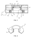
- FIG. 3 is a cut-out perspective view schematically illustrating a holder provided in a linear vibrator according to an exemplary embodiment of the present invention
- FIG. 4 is a cross-sectional view schematically illustrating a linear vibrator according to another exemplary embodiment of the present invention.
- FIG. 5 is an exploded perspective view schematically illustrating the coupling of a holder, an elastic member and a lower case provided in a linear vibrator according to another exemplary embodiment of the present invention.
- FIG. 6 is a cross-sectional view schematically illustrating a linear vibrator according to another exemplary embodiment of the present invention.
- FIG. 1 is an exploded perspective view schematically illustrating a linear vibrator according to an exemplary embodiment of the present invention.
- FIG. 2 is a cross-sectional view schematically illustrating a linear vibrator according to an exemplary embodiment of the present invention.
- FIG. 3 is a cut-out perspective view schematically illustrating a holder provided in a linear vibrator according to an exemplary embodiment of the present invention.
- a linear vibrator 100 may include a fixing unit 140 , a magnetic field unit 120 , a vibration unit 130 and an elastic member 90 .
- the fixing unit 140 may be sealed such that an upper case 10 is an accommodation part having an internal space of a certain size and its lower portion being open downwardly is sealed by a lower case 15 .
- the upper and lower cases 10 and 15 may form an accommodation space of the magnetic field unit 120 , the vibration unit 130 , and the like to be described below.
- the upper and lower cases 10 and 15 may be integrally formed.
- the magnetic field unit 120 may include a magnet 30 and a lower plate 40 .
- the magnet 30 may be in contact with an inner sealing surface of the upper portion of the upper case 10 .
- the magnet 30 may be a cylindrical permanent magnet having upper and lower portions magnetized to have different polarities in a vertical direction to generate a magnetic force having a predetermined magnitude.
- the magnet may be bonded by a bonding material so as to be fixed to the inner sealing surface of the upper portion of the upper case 10 .
- the lower plate 40 may be provided on a lower surface of the magnet 30 so as to smoothly form a magnetic flux under the magnet 30 by passing through a coil 60 generating electromagnetic force through interaction with the magnet 30 .
- a magnetic fluid 50 may be coated between the coil 60 and the outer circumferential surfaces of the magnet 30 and the lower plate 40 .
- the magnetic fluid 50 may prevent the abnormal vibrations of the vibration unit 130 to be descried below.
- the magnetic fluid 50 may be provided in a gap formed between the magnet 30 and the coil 60 so as to allow for smooth vertical movements of the vibration unit 130 .
- the vibration unit 130 causes horizontal vibrations in an event that it vibrates from side to side due to an external impact
- the magnetic fluid 50 may prevent the horizontal vibrations, allow the vibration unit 130 to vibrate in a linear manner, and prevent a minute vibration phenomenon.
- the magnetic fluid 50 is a material characterized by focusing on the magnetic flux of the magnet 30 .
- the magnetic fluid 50 may focus on a position where the magnetic flux of the magnet 30 is generated to thereby form a ring shape.
- the magnetic fluid 50 is obtained by stably dispersing magnetic powder in a colloid shape in a liquid and then adding a surfactant thereto to prevent the magnetic powder from being precipitated or coagulated due to gravitation or a magnetic field.
- the magnetic fluid 50 may include a magnetic fluid obtained by dispersing triiron tetroxide or iron-cobalt alloy molecules in oil or water and, recently, a magnetic fluid obtained by dispersing cobalt in toluene.
- the magnetic powder is ultrafine particle powder, has Brownian motion peculiar to ultrafine particles, and has the characteristics that the concentration of the magnetic powder particles in the fluid is uniformly maintained even when an external magnetic field, gravitation, centrifugal force, etc., is applied thereto.
- the magnetic fluid 50 fills a gap between an outer surface of the magnet 30 and an inner surface of a hollow of the coil 60 , thereby allowing the vibration unit 130 to smoothly vibrate or slide.
- the vibration unit 130 may include the coil 60 , a holder 70 and a mass body 80 .
- the vibration unit 130 may vibrate vertically by the use of the elastic member 90 to be described below.
- the coil 60 may be disposed to face the magnet 30 , and part of the magnet 30 may be inserted into a space provided by the coil 60 .
- the coil 60 may be coupled with an inner surface of a hollow of the holder 70 .
- a magnetic field may be generated around the coil 60 .
- the magnetic flux passing through the coil 60 from the magnet 30 is directed horizontally and the magnetic field generated by the coil 60 is formed vertically, so that the vibration unit 130 vibrates vertically. Accordingly, the direction of magnetic flux of the magnet 30 is perpendicular to the vibration direction of the vibration unit 130 .
- the vibration unit 130 may develop resonance vibrations to thereby obtain the maximum amount of vibrations.
- the natural frequency of the vibration unit 130 is affected by the mass of the vibration unit 130 and the modulus of elasticity of the elastic member 90 .
- the holder 70 may be coupled with an outer circumferential surface of the coil 60 , fixedly support the mass body 80 which vibrates, and have a shape of a hollow cylinder whose upper and lower surfaces are open.
- the holder 70 may include a vertical portion 72 coupled with the outer circumferential surface of the coil 60 by being in contact therewith and having a shape of a cylinder, and a horizontal portion 74 extending from an end of the vertical portion 72 in an outer diameter direction.
- An outer circumferential surface of the vertical portion 72 and an upper surface of the horizontal portion 74 may be in contact with the mass body 80 to fixedly support the mass body 80 , and a lower surface of the horizontal portion 74 may be coupled with the elastic member 90 to be described below.
- the holder 70 may be formed of iron (Fe). This is intended to facilitate and secure the coupling of the holder 70 and the elastic member 90 by allowing the holder 70 to be formed of the same material as that of the elastic member 90 .
- the material of the holder 70 and the elastic member 90 is not limited to iron (Fe).
- the holder 70 and the elastic member 90 may be formed of any material, as long as the material allows for the facilitation of secure coupling.
- the holder 70 may have an upper coupling portion 110 a on a bottom surface thereof such that the upper coupling portion 110 a is in contact with the elastic member 90 .
- the upper coupling portion 110 a may be a portion where the bottom surface of the holder 70 and the elastic member 90 are coupled by welding.
- the mass body 80 is a vibration body being coupled with the outer surface of the vertical portion 72 and the upper surface of the horizontal portion 74 and vibrating vertically.
- the mass body 80 may have an outer diameter smaller than an inner diameter of an inner surface of the upper case 10 to allow the mass body 80 to vibrate within the fixing unit 140 without any contact.
- a gap of a certain size may be formed between the inner surface of the upper case 10 and an outer surface of the mass body 80 .
- the mass body 80 may be formed of nonmagnetic or paramagnetic substances that are not affected by the magnetic force generated from the magnet 30 .
- the mass body 80 may be formed of a material, such as tungsten, having a greater specific gravity than iron. This is intended to maximize the amount of vibrations by controlling a resonance frequency due to an increase in the mass of the vibration unit 130 within a limited volume.
- the material of the mass body 80 is not limited to tungsten.
- the mass body 80 may be formed of various materials according to a designer's intention.
- the mass body 80 may be expanded such that the side surface thereof has a further increased mass. This is also intended to maximize the amount of vibrations by increasing the mass within a limited volume.
- the mass body 80 may include a space into which a sub-mass body is further inserted, thereby allowing its mass to be increased and decreased.
- the elastic member 90 is coupled with the holder 70 and the lower case 15 and provides elastic force to the vibration unit 130 .
- the elastic member 90 may include a plurality of elastic members. The modulus of elasticity of the elastic member 90 may affect the natural frequency of the vibration unit 130 .
- One end of the elastic member 90 may be coupled with the bottom surface of the horizontal portion 74 of the holder 70 , thereby forming the upper coupling portion 110 a.
- the upper coupling portion 110 a may be a portion where the one end of the elastic member 90 and the bottom surface of the horizontal portion 74 are coupled by welding. As described above, the elastic member 90 and the holder 70 may be formed of the same material, so that the coupling thereof by the welding may be facilitated and secured.
- the elastic member 90 may be any one of a coil spring and a plate spring. An example of using the plate spring will be described with reference to FIGS. 4 and 5 .
- the elastic member 90 is not limited to the above-mentioned spring, and it may have various forms as long as it provides elastic force.
- the other end of the elastic member 90 may be coupled with a surface of the lower case 15 by welding, thereby forming a lower coupling portion 110 b.
- a flexible printed circuit board (not shown) may be provided on an upper surface of the lower case 15 so as to make electrical connections with the coil 60 .
- the other end of the elastic member 90 may be coupled with the printed circuit board by welding to thereby form the lower coupling portion 110 b.
- a damper 20 may be formed on the inner sealing surface of the upper portion of the upper case 10 .
- the damper 20 may have a structure accommodating the magnet 30 .
- the damper 20 may be formed of elastic material so as to prevent contact between the vibration unit 130 and the upper case 10 induced by the linear movements of the vibration unit 130 .
- the damper 20 may prevent touch noise that may occur in a case in which the vibration unit 130 excessively vibrates to be in contact with the upper case 10 , and also prevent abrasion of the vibration unit 130 .
- the damper 20 may absorb an external impact to extend the life span of the linear vibrator 100 .
- the damper 20 may be formed of various materials, such as rubber, cork, propylene, or the like, capable of absorbing the impact.
- FIG. 4 is a cross-sectional view schematically illustrating a linear vibrator according to another exemplary embodiment of the present invention.
- FIG. 5 is an exploded perspective view schematically illustrating the coupling of a holder, an elastic member and a lower case provided in a linear vibrator according to another exemplary embodiment of the present invention.
- the linear vibrator 100 has the same constitution and effect as those of the above-described embodiment with the exception of the elastic member 90 , so a detailed description thereof will be omitted.
- the elastic member 90 may be a plate spring, and a portion thereof being protruded upwardly may be coupled with the horizontal portion 74 of the holder 70 by welding.
- the protruded portion and the horizontal portion 74 may be coupled to form the upper coupling portion 110 a .
- the holder 70 and the elastic member 90 i.e., the plate spring, may be formed of the same material.
- a lower portion of the plate spring may be coupled with a surface of the lower case 15 by welding, thereby forming the lower coupling portion 110 b.
- a flexible printed circuit board (not shown) may be provided on the upper surface of the lower case 15 so as to make electrical connections with the coil.
- the lower portion of the elastic member 90 may be coupled with the printed circuit board by welding to thereby form the lower coupling portion 110 b.
- FIG. 6 is a cross-sectional view schematically illustrating a linear vibrator according to another exemplary embodiment of the present invention.
- the linear vibrator 100 has the same constitution and effect as those of the above-described embodiment with the exception of a coupling structure of the elastic member 90 and the holder 70 , so a detailed description thereof will be omitted.
- the holder 70 may include the vertical portion 72 being in contact with a surface of the coil 60 and having a shape of a cylinder whose lower portion is sealed, and the horizontal portion 74 extending from an end of the vertical portion 72 in an outer diameter direction.
- one end of the elastic members 90 may be individually coupled with a bottom surface of the horizontal portion 74 and a bottom surface of the sealed lower portion of the vertical portion 72 by welding and the other end thereof may be coupled with a surface of the lower case 15 .
- the holder 70 may fixedly support the mass body 80 and the coil 60 and the elastic member 90 may be coupled with the holder 70 and the fixing unit 140 by welding, thereby preventing the vibration unit from making abnormal vibrations and being separated from its preset portion due to an external force. Also, linear vibrations having greater stability may be achieved by preventing the abnormal vibrations of the vibration unit 30 .
- a linear vibrator may prevent a vibration unit from making abnormal vibrations to thereby achieve more stable linear vibrations and allow the vibration unit to stop the vibrations quickly and stably.
Abstract
Description
Claims (12)
Priority Applications (1)
| Application Number | Priority Date | Filing Date | Title |
|---|---|---|---|
| US14/150,232 US9071121B2 (en) | 2010-05-25 | 2014-01-08 | Linear vibrator |
Applications Claiming Priority (2)
| Application Number | Priority Date | Filing Date | Title |
|---|---|---|---|
| KR10-2010-0048815 | 2010-05-25 | ||
| KR1020100048815A KR101004879B1 (en) | 2010-05-25 | 2010-05-25 | Linear vibrator |
Related Child Applications (1)
| Application Number | Title | Priority Date | Filing Date |
|---|---|---|---|
| US14/150,232 Continuation US9071121B2 (en) | 2010-05-25 | 2014-01-08 | Linear vibrator |
Publications (2)
| Publication Number | Publication Date |
|---|---|
| US20110291497A1 US20110291497A1 (en) | 2011-12-01 |
| US9093888B2 true US9093888B2 (en) | 2015-07-28 |
Family
ID=43513499
Family Applications (2)
| Application Number | Title | Priority Date | Filing Date |
|---|---|---|---|
| US13/064,800 Expired - Fee Related US9093888B2 (en) | 2010-05-25 | 2011-04-15 | Linear vibrator |
| US14/150,232 Expired - Fee Related US9071121B2 (en) | 2010-05-25 | 2014-01-08 | Linear vibrator |
Family Applications After (1)
| Application Number | Title | Priority Date | Filing Date |
|---|---|---|---|
| US14/150,232 Expired - Fee Related US9071121B2 (en) | 2010-05-25 | 2014-01-08 | Linear vibrator |
Country Status (3)
| Country | Link |
|---|---|
| US (2) | US9093888B2 (en) |
| KR (1) | KR101004879B1 (en) |
| CN (1) | CN102263473B (en) |
Families Citing this family (36)
| Publication number | Priority date | Publication date | Assignee | Title |
|---|---|---|---|---|
| KR101060813B1 (en) * | 2010-05-14 | 2011-08-30 | 삼성전기주식회사 | A linear vibrator |
| KR101354867B1 (en) * | 2011-08-03 | 2014-01-23 | 삼성전기주식회사 | Linear vibration device |
| KR101860775B1 (en) * | 2011-10-10 | 2018-05-28 | 주식회사 엠플러스 | Linear vibrator |
| US8803373B2 (en) * | 2011-12-05 | 2014-08-12 | Samsung Electro-Mechanics Co., Ltd. | Linear vibration motor |
| JP2013233537A (en) * | 2012-04-10 | 2013-11-21 | Hosiden Corp | Vibrator |
| KR101461274B1 (en) | 2012-08-01 | 2014-11-17 | 삼성전기주식회사 | Linear Motor |
| KR101388816B1 (en) * | 2012-09-07 | 2014-04-30 | 삼성전기주식회사 | Linear vibrator |
| KR101525654B1 (en) * | 2012-12-06 | 2015-06-03 | 삼성전기주식회사 | Linear vibrator |
| CN104043575A (en) * | 2013-03-12 | 2014-09-17 | 可立新株式会社 | Vibration generating device |
| JP2015070729A (en) * | 2013-09-30 | 2015-04-13 | 日本電産コパル株式会社 | Information terminal processing device and vibration generator system |
| CN105207441B (en) * | 2015-09-23 | 2017-11-21 | 歌尔股份有限公司 | Linear vibration motor |
| CN105356713B (en) * | 2015-12-03 | 2018-10-02 | 歌尔股份有限公司 | A kind of linear vibration motor and its elastic supporting member for supporting optical member |
| CN106208603B (en) * | 2016-08-12 | 2018-09-28 | 歌尔股份有限公司 | The linear vibrator of the horizontally disposed double vibrational systems of magnetic circuit |
| KR102026901B1 (en) * | 2017-08-25 | 2019-11-04 | 주식회사 엠플러스 | A linear vibration generating device including a coil break preventing structure |
| KR101952301B1 (en) * | 2017-10-25 | 2019-02-26 | 주식회사 엠플러스 | A linear vibration motor having a plate-shaped spring having a bending portion |
| CN107910969A (en) * | 2017-11-16 | 2018-04-13 | 日本电产科宝电子(浙江)有限公司 | Core free motor |
| CN108187997A (en) * | 2018-01-25 | 2018-06-22 | 昆明理工大学 | A kind of cam-type Chaotic Vibration Exciter |
| GB2572350B (en) * | 2018-03-27 | 2023-01-25 | Hitachi Rail Ltd | An electromechanical generator for converting mechanical vibrational energy into electrical energy |
| GB2572349B (en) * | 2018-03-27 | 2021-08-11 | Perpetuum Ltd | An electromechanical generator for converting mechanical vibrational energy into electrical energy |
| JP7063691B2 (en) * | 2018-04-06 | 2022-05-09 | フォスター電機株式会社 | Vibration actuator |
| CN114337177A (en) * | 2018-08-28 | 2022-04-12 | 美蓓亚三美株式会社 | Vibration actuator and electronic device |
| KR102138339B1 (en) * | 2018-10-24 | 2020-07-27 | 주식회사 엠플러스 | Sound vibration actuator |
| US10932027B2 (en) | 2019-03-03 | 2021-02-23 | Bose Corporation | Wearable audio device with docking or parking magnet having different magnetic flux on opposing sides of the magnet |
| US11067644B2 (en) | 2019-03-14 | 2021-07-20 | Bose Corporation | Wearable audio device with nulling magnet |
| US11076214B2 (en) * | 2019-03-21 | 2021-07-27 | Bose Corporation | Wearable audio device |
| US11061081B2 (en) | 2019-03-21 | 2021-07-13 | Bose Corporation | Wearable audio device |
| CN113841423A (en) | 2019-04-11 | 2021-12-24 | 大陆工程服务有限公司 | Rigid structural vibration actuator for high performance bass playback in an automobile |
| US11272282B2 (en) | 2019-05-30 | 2022-03-08 | Bose Corporation | Wearable audio device |
| US20210013786A1 (en) * | 2019-07-08 | 2021-01-14 | West Virginia University | High frequency resonant linear machines |
| US20210067023A1 (en) * | 2019-08-30 | 2021-03-04 | Apple Inc. | Haptic actuator including shaft coupled field member and related methods |
| CN110545022B (en) * | 2019-09-11 | 2021-07-23 | 浙江省东阳市东磁诚基电子有限公司 | Linear motor with encircling elastic sheet structure and implementation method thereof |
| JP7410791B2 (en) * | 2020-04-28 | 2024-01-10 | ニデックインスツルメンツ株式会社 | actuator |
| CN113572333B (en) * | 2020-04-28 | 2024-03-29 | 日本电产三协株式会社 | Actuator with a spring |
| JP2022049071A (en) * | 2020-09-16 | 2022-03-29 | 株式会社東芝 | Vibration generator |
| CN112564541B (en) * | 2020-12-09 | 2021-09-28 | 上海大学 | Electromagnetic friction electric hybrid energy collector for low-frequency motion |
| CN217388499U (en) * | 2021-05-06 | 2022-09-06 | 瑞声光电科技(常州)有限公司 | Linear vibration motor |
Citations (21)
| Publication number | Priority date | Publication date | Assignee | Title |
|---|---|---|---|---|
| JP2001340811A (en) | 2000-05-30 | 2001-12-11 | Nidec Copal Corp | Vibration generation apparatus |
| US20050184601A1 (en) * | 2004-02-23 | 2005-08-25 | Kweon Soon D. | Linear vibration motor using resonance frequency |
| KR20050083528A (en) | 2004-02-23 | 2005-08-26 | 삼성전기주식회사 | Linear type vibration motor using resonance frequency |
| US7038335B2 (en) * | 2004-06-23 | 2006-05-02 | Samsung Electro-Mechanics Co., Ltd. | Vertical vibrator |
| US7170205B2 (en) * | 2004-07-01 | 2007-01-30 | Samsung Electro-Mechanics Co., Ltd. | Internal weight type vertical vibrator |
| US20070182257A1 (en) | 2006-01-10 | 2007-08-09 | Naoki Miura | Vibrator |
| JP2007203227A (en) | 2006-02-03 | 2007-08-16 | Citizen Electronics Co Ltd | Vibrator |
| US20070194635A1 (en) * | 2006-02-23 | 2007-08-23 | Citizen Electronics Co., Ltd. | Vibrator |
| KR20080074329A (en) | 2007-02-08 | 2008-08-13 | 엘지이노텍 주식회사 | Linear vibrator |
| US20080306332A1 (en) * | 2007-06-07 | 2008-12-11 | Samsung Electro-Mechanics Co., Ltd. | Linear vibration generator |
| KR100895993B1 (en) | 2009-01-07 | 2009-05-07 | 주식회사 블루콤 | Linear vibration device |
| US20090121559A1 (en) | 2007-11-12 | 2009-05-14 | Kap Jin Lee | Vibration Device and Method of Fabricating the Same |
| KR100898017B1 (en) | 2009-02-23 | 2009-05-19 | 주식회사 블루콤 | Linear vibration device |
| US7576462B2 (en) * | 2005-05-30 | 2009-08-18 | Citizen Electronics Co., Ltd. | Electromagnetic exciter |
| KR100923867B1 (en) | 2009-07-21 | 2009-10-28 | 김태진 | Linear vibration motor |
| US7619498B2 (en) * | 2006-04-06 | 2009-11-17 | Citizen Electronics Co., Ltd. | Vibrator |
| KR100934584B1 (en) | 2009-06-16 | 2009-12-31 | 유성정밀 주식회사 | Linear vibrator |
| KR20100052753A (en) | 2008-11-11 | 2010-05-20 | 주식회사 예일전자 | Coin type linear motor |
| US8134259B2 (en) * | 2009-12-03 | 2012-03-13 | Samsung Electro-Mechanics Co., Ltd. | Linear vibrator |
| US8450887B2 (en) * | 2010-02-08 | 2013-05-28 | Samsung Electro-Mechanics Co., Ltd. | Vertical vibrator |
| US8461729B2 (en) * | 2010-05-14 | 2013-06-11 | Samsung Electro-Mechanics Co., Ltd. | Linear vibrator |
-
2010
- 2010-05-25 KR KR1020100048815A patent/KR101004879B1/en active IP Right Grant
-
2011
- 2011-04-15 US US13/064,800 patent/US9093888B2/en not_active Expired - Fee Related
- 2011-05-24 CN CN201110145215.9A patent/CN102263473B/en not_active Expired - Fee Related
-
2014
- 2014-01-08 US US14/150,232 patent/US9071121B2/en not_active Expired - Fee Related
Patent Citations (23)
| Publication number | Priority date | Publication date | Assignee | Title |
|---|---|---|---|---|
| JP2001340811A (en) | 2000-05-30 | 2001-12-11 | Nidec Copal Corp | Vibration generation apparatus |
| US20050184601A1 (en) * | 2004-02-23 | 2005-08-25 | Kweon Soon D. | Linear vibration motor using resonance frequency |
| KR20050083528A (en) | 2004-02-23 | 2005-08-26 | 삼성전기주식회사 | Linear type vibration motor using resonance frequency |
| US7038335B2 (en) * | 2004-06-23 | 2006-05-02 | Samsung Electro-Mechanics Co., Ltd. | Vertical vibrator |
| US7170205B2 (en) * | 2004-07-01 | 2007-01-30 | Samsung Electro-Mechanics Co., Ltd. | Internal weight type vertical vibrator |
| US7576462B2 (en) * | 2005-05-30 | 2009-08-18 | Citizen Electronics Co., Ltd. | Electromagnetic exciter |
| US20070182257A1 (en) | 2006-01-10 | 2007-08-09 | Naoki Miura | Vibrator |
| JP2007203227A (en) | 2006-02-03 | 2007-08-16 | Citizen Electronics Co Ltd | Vibrator |
| US20070194635A1 (en) * | 2006-02-23 | 2007-08-23 | Citizen Electronics Co., Ltd. | Vibrator |
| US7619498B2 (en) * | 2006-04-06 | 2009-11-17 | Citizen Electronics Co., Ltd. | Vibrator |
| KR20080074329A (en) | 2007-02-08 | 2008-08-13 | 엘지이노텍 주식회사 | Linear vibrator |
| US8130086B2 (en) * | 2007-06-07 | 2012-03-06 | Samsung Electro-Mechanics Co., Ltd. | Linear vibration generator |
| US20080306332A1 (en) * | 2007-06-07 | 2008-12-11 | Samsung Electro-Mechanics Co., Ltd. | Linear vibration generator |
| US20090121559A1 (en) | 2007-11-12 | 2009-05-14 | Kap Jin Lee | Vibration Device and Method of Fabricating the Same |
| KR20090048677A (en) | 2007-11-12 | 2009-05-15 | 엘지이노텍 주식회사 | Vibration motor and method for the same |
| KR20100052753A (en) | 2008-11-11 | 2010-05-20 | 주식회사 예일전자 | Coin type linear motor |
| KR100895993B1 (en) | 2009-01-07 | 2009-05-07 | 주식회사 블루콤 | Linear vibration device |
| KR100898017B1 (en) | 2009-02-23 | 2009-05-19 | 주식회사 블루콤 | Linear vibration device |
| KR100934584B1 (en) | 2009-06-16 | 2009-12-31 | 유성정밀 주식회사 | Linear vibrator |
| KR100923867B1 (en) | 2009-07-21 | 2009-10-28 | 김태진 | Linear vibration motor |
| US8134259B2 (en) * | 2009-12-03 | 2012-03-13 | Samsung Electro-Mechanics Co., Ltd. | Linear vibrator |
| US8450887B2 (en) * | 2010-02-08 | 2013-05-28 | Samsung Electro-Mechanics Co., Ltd. | Vertical vibrator |
| US8461729B2 (en) * | 2010-05-14 | 2013-06-11 | Samsung Electro-Mechanics Co., Ltd. | Linear vibrator |
Non-Patent Citations (7)
| Title |
|---|
| Chinese Office Action issued Apr. 3, 2013 in corresponding Chinese Patent Application No. 201110145215.9. |
| Chinese Office Action mailed Dec. 16, 2013 in corresponding Chinese Application No. 201110145215.9. |
| English Translation of Korean Reference No. 10-0923867. |
| Korean Office Action dated Mar. 13, 2012 issued in related Korean Patent Application No. 10-2010-0101539. |
| Korean Office Action issued May 14, 2015 in corresponding Korean Patent Application No. 10-2013-0064297. |
| Notice of Allowance mailed Feb. 23, 2015 in related U.S. Appl. No. 14/150,232. |
| U.S. Application Office Action dated Sep. 29, 2014 in copending U.S. Appl. No. 14/150,232. |
Also Published As
| Publication number | Publication date |
|---|---|
| US20110291497A1 (en) | 2011-12-01 |
| US9071121B2 (en) | 2015-06-30 |
| CN102263473A (en) | 2011-11-30 |
| KR101004879B1 (en) | 2010-12-28 |
| CN102263473B (en) | 2014-09-24 |
| US20140117787A1 (en) | 2014-05-01 |
Similar Documents
| Publication | Publication Date | Title |
|---|---|---|
| US9093888B2 (en) | Linear vibrator | |
| US8736121B2 (en) | Linear vibrator | |
| US8450887B2 (en) | Vertical vibrator | |
| US8669679B2 (en) | Linear vibrator | |
| KR101046044B1 (en) | Linear vibrator | |
| JP4939587B2 (en) | Linear vibration device | |
| KR101009112B1 (en) | Linear vibrator | |
| US8957558B2 (en) | Linear vibration generator | |
| US9085013B2 (en) | Linear vibrator | |
| KR20100119970A (en) | Linear vibrator | |
| US20130342034A1 (en) | Linear vibrator | |
| US8860264B2 (en) | Linear vibrator | |
| KR101300334B1 (en) | Linear vibrator | |
| KR101197873B1 (en) | Linear vibrator | |
| KR101250728B1 (en) | Linear vibrator | |
| KR20120049204A (en) | Linear vibrator | |
| KR20130065687A (en) | Linear vibrator | |
| KR20120035094A (en) | Linear vibrator | |
| CN102468736B (en) | Linear vibrator | |
| KR20100136178A (en) | Linear vibrator |
Legal Events
| Date | Code | Title | Description |
|---|---|---|---|
| AS | Assignment |
Owner name: SAMSUNG ELECTRO-MECHANICS CO., LTD., KOREA, REPUBL Free format text: ASSIGNMENT OF ASSIGNORS INTEREST;ASSIGNOR:CHOI, JUN KUN;REEL/FRAME:026213/0890 Effective date: 20110406 |
|
| FEPP | Fee payment procedure |
Free format text: PAYOR NUMBER ASSIGNED (ORIGINAL EVENT CODE: ASPN); ENTITY STATUS OF PATENT OWNER: SMALL ENTITY |
|
| STCF | Information on status: patent grant |
Free format text: PATENTED CASE |
|
| FEPP | Fee payment procedure |
Free format text: PAT HOLDER CLAIMS SMALL ENTITY STATUS, ENTITY STATUS SET TO SMALL (ORIGINAL EVENT CODE: LTOS); ENTITY STATUS OF PATENT OWNER: SMALL ENTITY |
|
| AS | Assignment |
Owner name: MPLUS CO., LTD., KOREA, REPUBLIC OF Free format text: ASSIGNMENT OF ASSIGNORS INTEREST;ASSIGNOR:SAMSUNG ELECTRO-MECHANICS CO., LTD.;REEL/FRAME:037962/0472 Effective date: 20160212 |
|
| MAFP | Maintenance fee payment |
Free format text: PAYMENT OF MAINTENANCE FEE, 4TH YR, SMALL ENTITY (ORIGINAL EVENT CODE: M2551); ENTITY STATUS OF PATENT OWNER: SMALL ENTITY Year of fee payment: 4 |
|
| FEPP | Fee payment procedure |
Free format text: MAINTENANCE FEE REMINDER MAILED (ORIGINAL EVENT CODE: REM.); ENTITY STATUS OF PATENT OWNER: SMALL ENTITY |
|
| LAPS | Lapse for failure to pay maintenance fees |
Free format text: PATENT EXPIRED FOR FAILURE TO PAY MAINTENANCE FEES (ORIGINAL EVENT CODE: EXP.); ENTITY STATUS OF PATENT OWNER: SMALL ENTITY |
|
| STCH | Information on status: patent discontinuation |
Free format text: PATENT EXPIRED DUE TO NONPAYMENT OF MAINTENANCE FEES UNDER 37 CFR 1.362 |
|
| FP | Lapsed due to failure to pay maintenance fee |
Effective date: 20230728 |