US9099142B2 - Radially dependent thermal heat resist layer - Google Patents

Radially dependent thermal heat resist layer Download PDF

Info

Publication number
US9099142B2
US9099142B2 US14/199,896 US201414199896A US9099142B2 US 9099142 B2 US9099142 B2 US 9099142B2 US 201414199896 A US201414199896 A US 201414199896A US 9099142 B2 US9099142 B2 US 9099142B2
Authority
US
United States
Prior art keywords
thickness
heat sink
gradient
layer
resist layer
Prior art date
Legal status (The legal status is an assumption and is not a legal conclusion. Google has not performed a legal analysis and makes no representation as to the accuracy of the status listed.)
Expired - Fee Related
Application number
US14/199,896
Other versions
US20140269231A1 (en
Inventor
René van de Veerdonk
Current Assignee (The listed assignees may be inaccurate. Google has not performed a legal analysis and makes no representation or warranty as to the accuracy of the list.)
Seagate Technology LLC
Original Assignee
Seagate Technology LLC
Priority date (The priority date is an assumption and is not a legal conclusion. Google has not performed a legal analysis and makes no representation as to the accuracy of the date listed.)
Filing date
Publication date
Priority to US14/199,896 priority Critical patent/US9099142B2/en
Application filed by Seagate Technology LLC filed Critical Seagate Technology LLC
Priority to CN201480010650.2A priority patent/CN105027208B/en
Priority to MYPI2015703039A priority patent/MY182233A/en
Priority to JP2016501745A priority patent/JP2016511503A/en
Priority to PCT/US2014/025103 priority patent/WO2014165290A1/en
Priority to TW103108656A priority patent/TW201506917A/en
Priority to KR1020157027965A priority patent/KR20150130403A/en
Priority to SG11201507337RA priority patent/SG11201507337RA/en
Assigned to SEAGATE TECHNOLOGY LLC reassignment SEAGATE TECHNOLOGY LLC ASSIGNMENT OF ASSIGNORS INTEREST (SEE DOCUMENT FOR DETAILS). Assignors: VAN DE VEERDONK, RENÉ
Publication of US20140269231A1 publication Critical patent/US20140269231A1/en
Application granted granted Critical
Publication of US9099142B2 publication Critical patent/US9099142B2/en
Expired - Fee Related legal-status Critical Current
Anticipated expiration legal-status Critical

Links

Images

Classifications

    • GPHYSICS
    • G11INFORMATION STORAGE
    • G11BINFORMATION STORAGE BASED ON RELATIVE MOVEMENT BETWEEN RECORD CARRIER AND TRANSDUCER
    • G11B5/00Recording by magnetisation or demagnetisation of a record carrier; Reproducing by magnetic means; Record carriers therefor
    • G11B5/74Record carriers characterised by the form, e.g. sheet shaped to wrap around a drum
    • G11B5/82Disk carriers
    • G11B5/7325
    • GPHYSICS
    • G11INFORMATION STORAGE
    • G11BINFORMATION STORAGE BASED ON RELATIVE MOVEMENT BETWEEN RECORD CARRIER AND TRANSDUCER
    • G11B5/00Recording by magnetisation or demagnetisation of a record carrier; Reproducing by magnetic means; Record carriers therefor
    • G11B5/62Record carriers characterised by the selection of the material
    • G11B5/73Base layers, i.e. all non-magnetic layers lying under a lowermost magnetic recording layer, e.g. including any non-magnetic layer in between a first magnetic recording layer and either an underlying substrate or a soft magnetic underlayer
    • G11B5/7368Non-polymeric layer under the lowermost magnetic recording layer
    • G11B5/7369Two or more non-magnetic underlayers, e.g. seed layers or barrier layers
    • GPHYSICS
    • G11INFORMATION STORAGE
    • G11BINFORMATION STORAGE BASED ON RELATIVE MOVEMENT BETWEEN RECORD CARRIER AND TRANSDUCER
    • G11B5/00Recording by magnetisation or demagnetisation of a record carrier; Reproducing by magnetic means; Record carriers therefor
    • G11B5/62Record carriers characterised by the selection of the material
    • G11B5/73Base layers, i.e. all non-magnetic layers lying under a lowermost magnetic recording layer, e.g. including any non-magnetic layer in between a first magnetic recording layer and either an underlying substrate or a soft magnetic underlayer
    • G11B5/7368Non-polymeric layer under the lowermost magnetic recording layer
    • G11B5/7375Non-polymeric layer under the lowermost magnetic recording layer for heat-assisted or thermally-assisted magnetic recording [HAMR, TAMR]
    • GPHYSICS
    • G11INFORMATION STORAGE
    • G11BINFORMATION STORAGE BASED ON RELATIVE MOVEMENT BETWEEN RECORD CARRIER AND TRANSDUCER
    • G11B5/00Recording by magnetisation or demagnetisation of a record carrier; Reproducing by magnetic means; Record carriers therefor
    • G11B2005/0002Special dispositions or recording techniques
    • G11B2005/0005Arrangements, methods or circuits
    • G11B2005/0021Thermally assisted recording using an auxiliary energy source for heating the recording layer locally to assist the magnetization reversal
    • GPHYSICS
    • G11INFORMATION STORAGE
    • G11BINFORMATION STORAGE BASED ON RELATIVE MOVEMENT BETWEEN RECORD CARRIER AND TRANSDUCER
    • G11B5/00Recording by magnetisation or demagnetisation of a record carrier; Reproducing by magnetic means; Record carriers therefor
    • G11B5/74Record carriers characterised by the form, e.g. sheet shaped to wrap around a drum
    • G11B5/743Patterned record carriers, wherein the magnetic recording layer is patterned into magnetic isolated data islands, e.g. discrete tracks
    • G11B5/746Bit Patterned record carriers, wherein each magnetic isolated data island corresponds to a bit

Landscapes

  • Recording Or Reproducing By Magnetic Means (AREA)
  • Magnetic Record Carriers (AREA)

Abstract

The embodiments disclose a data storage device including a thickness gradient heat sink layer deposited over a heat sink layer deposited over a substrate, a thickness gradient non-magnetic thermal resist layer deposited over the thickness gradient heat sink layer, and a magnetic layer deposited over the thickness gradient non-magnetic thermal resist layer.

Description

CROSS-REFERENCE TO RELATED APPLICATIONS
This application is based on U.S. Provisional Patent Application Ser. No. 61/778,370 filed Mar. 12, 2013, entitled “A Radially Dependent Thermal Heat Resistor Layer”, by First Named Inventor René van de Veerdonk.
BRIEF DESCRIPTION OF THE DRAWINGS
FIG. 1 shows a block diagram of an overview of a radially dependent thermal heat resistor layer of one embodiment.
FIG. 2 shows for illustrative purposes only an example of a thickness gradient heat sink layer of one embodiment.
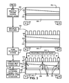
FIG. 3 shows for illustrative purposes only an example of a radially dependent thermal heat resistor layer structure of one embodiment.
FIG. 4A shows for illustrative purposes only an example of a thickness gradient heat sink layer deposition of one embodiment.
FIG. 4B shows for illustrative purposes only an example of a non-magnetic thermal resist layer deposition of one embodiment.
DETAILED DESCRIPTION OF THE INVENTION
In a following description, reference is made to the accompanying drawings, which form a part hereof, and in which is shown by way of illustration a specific example in which the invention may be practiced. It is to be understood that other embodiments may be utilized and structural changes may be made without departing from the scope of the present invention.
General Overview:
It should be noted that the descriptions that follow, for example, in terms of a radially dependent thermal heat resistor layer is described for illustrative purposes and the underlying system can apply to any number and multiple types sputter sources. In one embodiment of the present invention, the radially dependent thermal heat resistor layer can be configured using an intentional variation across the radial direction of media surface. The radially dependent thermal heat resistor layer can be configured to include a graded thermal resistor layer and can be configured to include a thickness and/or composition gradient across the radius of the disk using the present invention. Herein the term “graded” has a contextual meaning of an intentional variation across the radial direction of a media surface.
Heat Assisted Magnetic Recording (HAMR) is a novel recording technology slated for implementation in future hard-disk drives. The technology is based on heating the media to reduce its effective coercivity, and recording the information while the media cools down in an applied magnetic field. The speed of heating and cooling is critical in the recording process. This rate is controlled by the linear velocity of the recording head and the thermal time constant of the media.
The media layer stack is designed such that there is a thermal resistor layer directly underneath the recording layer. By tuning the properties of this layer (using thickness, composition, and/or multi-layering) the thermal time constant of the media can be matched to the requirements of the recording head. The result with this approach is that the linear velocity of the media is not a constant across the stroke of the media. For example, at a near-ID radius of 15 mm, the linear velocity will be half that of a near-OD radius of 30 mm due to tangential speeds. This means that the thermal time-constant for the media cannot be matched across the full stroke of the media surface.
The radially dependent thermal heat resistor layer uses a graded thermal resistor layer, where graded in this context means an intentional variation across the radial direction of media surface. Using triatron or other dedicated sputter sources, it is possible to engineer a thickness and/or composition gradient across the radius of the disk. By engineering the thermal resistor properties as a function of the radial position on the disk, the media thermal time constant profile can be matched against the linear velocity profile. This in turn will translate in an improved robustness of the HAMR recording system.
FIG. 1 shows a block diagram of an overview of a radially dependent thermal heat resistor layer of one embodiment. FIG. 1 shows a radially dependent thermal heat resistor layer and heat sink layer 100. The radially dependent thermal heat resistor layer and heat sink layer includes at least two inverse gradient layers across a radius of the device. The radially dependent thermal heat resistor layer and heat sink layer 100 includes a graded thermal resistor layer and heat sink layer, wherein graded in this context means an intentional variation across the radial direction of media surface 110.
The intentional variations across the radial direction of media surface is created using a thickness and/or composition gradient structure in the graded thermal resistor layer and heat sink layer across the radius of the disk using a dedicated sputter sources 120. The intentional variations in the gradient structure includes at least two inverse gradient layers configured to include a thickness range configured as linear, parabolic, polynomial or other forms that are adaptive according to thermal conditions and simulations 130. The gradient structure includes a thermal heat resistor layer and heat sink layer with properties pre-determined as a function of the radial position on a disk, wherein the media thermal time constant profile can be matched against the linear velocity profile creating a robustness of the HAMR recording system 140 of one embodiment.
Detailed Description
FIG. 2 shows a block diagram of an overview flow chart of a thickness gradient heat sink layer of one embodiment. FIG. 2 shows a substrate 200 wherein the substrate 200 is circular and includes an inner diameter, ID 210 and an outer diameter, OD 220. The substrate 200 can include using materials including quartz, silicone and other materials. Deposited onto the substrate 200 is a continuous heat sink layer 230 with a constant thickness. The continuous heat sink layer 230 can include using materials with predetermined properties of thermal conductivity of one embodiment.
A thickness gradient heat sink layer 240 is deposited on the continuous heat sink layer 230. The thickness gradient heat sink layer 240 is part of the gradient structure that compensates for recording tangential speeds with heat assisted magnetic recording 250. The thickness gradient heat sink layer 240 can include using materials with predetermined properties of thermal conductivity. FIG. 2 shows where from the ID 210 the thickness gradient heat sink layer 240 is diminishing in thickness as the radial distance increases toward to OD 220. The thickness gradient of the thickness gradient heat sink layer 240 material is configured to correlate to the changes in the linear velocity of the recording head and the thermal time constant of the media of one embodiment. The fabrication process is further described in FIG. 3.
FIG. 3 shows a block diagram of an overview flow chart of a radially dependent thermal heat resistor layer structure of one embodiment. FIG. 3 shows a continuation from FIG. 2 that includes a non-magnetic graded thermal resist layer 300 deposited on top of the thickness gradient heat sink layer 240 on the continuous heat sink layer 230. The non-magnetic graded thermal resist layer 300 is part of the gradient structure that compensates for recording tangential speeds with heat assisted magnetic recording 250. The non-magnetic graded thermal resist layer 300 can include using materials including with predetermined properties of thermal conductivity of one embodiment.
FIG. 3 shows the thickness of the non-magnetic graded thermal resist layer 300 diminishing from the OD 220 to the ID 210 of the substrate 200. The thickness gradient of the non-magnetic graded thermal resist layer 300 material is configured to correlate to the changes in the linear velocity of the recording head and the thermal time constant of the media of one embodiment.
On top of the non-magnetic graded thermal resist layer 300 magnetic features 310 are formed by deposition magnetic materials that can be patterned and used in a heat assisted magnetic recording (HAMR) mode of operation. A HAMR recording system 320 applies heat to the magnetic features 310 to facilitate the recording operation. The gradient structure including the non-magnetic graded thermal resist layer 300, thickness gradient heat sink layer 240 and continuous heat sink layer 230 are used to control the heat level in the magnetic features 310 during a recording operation.
The control the heat level in the magnetic features 310 during a recording operation includes compensating graded heat dissipation 330 of the recording head heat assist 340. The control of the heat dissipation corresponds to the linear velocity of the recording head as it changes with the movement of the recording head back and forth between the ID 210 and OD 220 of the substrate 200. The rate of dissipation using a radially dependent thermal heat resistor layer structure 350 compensates for the thermal time constant of the media of one embodiment.
FIG. 4A shows for illustrative purposes only an example of a thickness gradient heat sink layer deposition of one embodiment. FIG. 4A shows a dedicated sputter source 400 used to make a thickness gradient heat sink layer deposition 410 on top of the continuous heat sink layer 230. The dedicated sputter source 400 deposits a thickness=A1 420 at the OD 220 of the substrate 200. The dedicated sputter source 400 is configured to increase the thickness of the thickness gradient heat sink layer 240 deposition to a thickness A2>A1 and ≦2×a1 430 at the ID 210 of the substrate 200. The gradient of the graded heat sink layer across the radius of the device is configured to include a thickness range configured as linear, parabolic, polynomial or other forms that are adaptive according to thermal conditions and simulations. The gradient heat sink layer 240 includes for example a thickness range: A1: 5 to 200 nm 425 of one embodiment.
FIG. 4B shows for illustrative purposes only an example of a non-magnetic thermal resist layer deposition of one embodiment. FIG. 4B shows a dedicated sputter source 400 used for a non-magnetic graded thermal resist layer deposition 440. The non-magnetic graded thermal resist layer deposition 440 has a thickness=B1 450 at an inner circumference ID 210 and at the outer circumference OD 220 a thickness B2>B1 and ≦2×B1 460. The gradient of the non-magnetic graded thermal resist layer across the radius of the device is configured to include a thickness range configured as linear, parabolic, polynomial or other forms that are adaptive according to thermal conditions and simulations. The non-magnetic graded thermal resist layer deposition 440 includes for example a thickness Range: B1: 1 to 50 nm 455 of one embodiment.
The top surface of the non-magnetic graded thermal resist layer deposition 440 is a smooth level surface 470 parallel to the substrate 200 and of a non-coarse finish free of undulating topography. The non-magnetic graded thermal resist layer 300 is deposited on the thickness gradient heat sink layer 240, which is on top of the heat sink layer 230 on and in contact with the substrate 200 of one embodiment.
The foregoing has described the principles, embodiments and modes of operation of the present invention. However, the invention should not be construed as being limited to the particular embodiments discussed. The above described embodiments should be regarded as illustrative rather than restrictive, and it should be appreciated that variations may be made in those embodiments by workers skilled in the art without departing from the scope of the present invention as defined by the following claims.

Claims (21)

What is claimed is:
1. A data storage disk, comprising:
a radial thickness-gradient heat sink layer deposited over a heat sink layer deposited over a substrate;
a radial thickness-gradient, non-magnetic thermal resist layer deposited over the thickness-gradient heat sink layer; and
a magnetic layer deposited over the thermal resist layer.
2. The data storage disk of claim 1,
wherein the thermal resist layer and the thickness-gradient heat sink layer properties include a radial position function whereby a media thermal time constant profile is matched against a linear velocity profile.
3. An apparatus, comprising:
a second heat sink layer deposited over a first heat sink layer deposited over a disk-shaped substrate,
wherein the second heat sink layer includes a radial thickness gradient;
a non-magnetic thermal resist layer deposited over the second heat sink layer,
wherein the thermal resist layer includes a radial thickness gradient; and
a magnetic layer deposited over the thermal resist layer configured for magnetic recording.
4. The apparatus of claim 3,
wherein the second heat sink layer includes a thickness at an outer diameter equal to a value A1 and a thickness at an inner diameter equal to a value A2, and
wherein A2>A1, A2≦2·A1, and A1 is 5 to 200 nm.
5. The apparatus of claim 3,
wherein the thermal resist layer includes a thickness at an inner diameter equal to a value B1 and a thickness at an outer diameter equal to a value B2, and
wherein B2>B1, B2≦2·B1, and B1 is 1 to 50 nm.
6. The data storage disk of claim 1,
wherein the thermal resist layer includes a smooth level top surface parallel to the substrate and a non-coarse finish free of undulating topography.
7. The apparatus of claim 3,
wherein the thickness gradient of the thermal resist layer and the thickness gradient of the second heat sink layer are configured for compensating graded heat dissipation and recording time changes with heat-assisted magnetic recording.
8. The apparatus of claim 3,
wherein the thermal resist layer includes at least one material used for compensating graded heat dissipation.
9. The data storage disk of claim 2,
wherein the materials for each of the thermal resist layer and the heat sink layer facilitate matching the media thermal time constant profile against the linear velocity profile.
10. An apparatus, comprising:
a multi-layered disk configured for data storage including at least two radially inversed thickness-gradient layers configured to compensate for recording tangential speeds with heat-assisted magnetic recording,
wherein one of the at least two radially inversed thickness-gradient layers includes a first thickness-gradient layer including a non-magnetic thermal resist layer deposited on a heat sink layer.
11. The apparatus of claim 10,
wherein the thermal resist layer includes a thickness at an inner diameter equal to a value B1 and a thickness at an outer diameter equal to a value B2, and
wherein B2>B1, B2≦2·B1, and B1 is 1 to 50 nm.
12. The apparatus of claim 10,
wherein another one of the at least two radially inversed thickness-gradient layers includes a second thickness-gradient layer including the heat sink layer,
wherein the heat sink layer includes a thickness at an outer diameter equal to a value A1 and a thickness at an inner diameter equal to a value A2, and
wherein A2>A1, A2≦2·A1, and A1 is 5 to 200 nm.
13. The apparatus of claim 10,
wherein the radially inversed thickness-gradient layers are deposited on a uniformly thick heat sink layer deposited on a substrate, and
wherein the radially inversed thickness-gradient layers include thickness profiles configured as linear, parabolic, or polynomial.
14. The apparatus of claim 10,
wherein the radially inversed thickness-gradient layers are configured for compensating graded heat dissipation to match a media thermal time constant profile against a linear velocity profile.
15. A structure, comprising:
a disk-shaped substrate;
a first heat sink layer deposited over the substrate;
a second heat sink layer deposited over the first heat sink layer,
wherein the second heat sink layer includes a radial thickness gradient;
a non-magnetic thermal resist layer deposited over the second heat sink layer,
wherein the thermal resist layer includes a radial thickness gradient inversely related to the thickness gradient of the second heat sink layer; and
a magnetic layer deposited over the thermal resist layer configured for magnetic recording.
16. The structure of claim 15,
wherein the thickness gradient of the second heat sink layer and the thickness gradient of the thermal resist layer include inversely related thickness profiles configured as linear, parabolic, or polynomial.
17. The structure of claim 15,
wherein the thermal resist layer includes a thickness at an inner diameter equal to a value B1 and a thickness at an outer diameter equal to a value B2, and
wherein B2>B1, B2≦2·B1, and B1 is 1 to 50 nm.
18. The structure of claim 15,
wherein the second heat sink layer includes a thickness at an outer diameter equal to a value A1 and a thickness at an inner diameter equal to a value A2, and
wherein A2>A1, A2≦2·A1, and A1 is 5 to 200 nm.
19. The apparatus of claim 3,
wherein the thickness gradient of the thermal resist layer and the thickness gradient of the second heat sink layer are radially inversed and configured to include a thickness profile configured as linear, parabolic, or polynomial.
20. The apparatus of claim 3,
wherein the magnetic layer comprises patterned magnetic features configured for heat-assisted magnetic recording.
21. The structure of claim 15,
wherein the magnetic layer comprises patterned magnetic features configured for heat-assisted magnetic recording.
US14/199,896 2013-03-12 2014-03-06 Radially dependent thermal heat resist layer Expired - Fee Related US9099142B2 (en)

Priority Applications (8)

Application Number Priority Date Filing Date Title
US14/199,896 US9099142B2 (en) 2013-03-12 2014-03-06 Radially dependent thermal heat resist layer
MYPI2015703039A MY182233A (en) 2013-03-12 2014-03-12 Radially dependent thermal heat resist layer
JP2016501745A JP2016511503A (en) 2013-03-12 2014-03-12 Radial direction heat resistance layer
PCT/US2014/025103 WO2014165290A1 (en) 2013-03-12 2014-03-12 A radially dependent thermal heat resistor layer
CN201480010650.2A CN105027208B (en) 2013-03-12 2014-03-12 A radially dependent thermal heat resistor layer
TW103108656A TW201506917A (en) 2013-03-12 2014-03-12 A radially dependent thermal heat resistor layer
KR1020157027965A KR20150130403A (en) 2013-03-12 2014-03-12 A radially dependent thermal heat resistor layer
SG11201507337RA SG11201507337RA (en) 2013-03-12 2014-03-12 A radially dependent thermal heat resistor layer

Applications Claiming Priority (2)

Application Number Priority Date Filing Date Title
US201361778370P 2013-03-12 2013-03-12
US14/199,896 US9099142B2 (en) 2013-03-12 2014-03-06 Radially dependent thermal heat resist layer

Publications (2)

Publication Number Publication Date
US20140269231A1 US20140269231A1 (en) 2014-09-18
US9099142B2 true US9099142B2 (en) 2015-08-04

Family

ID=51526579

Family Applications (1)

Application Number Title Priority Date Filing Date
US14/199,896 Expired - Fee Related US9099142B2 (en) 2013-03-12 2014-03-06 Radially dependent thermal heat resist layer

Country Status (8)

Country Link
US (1) US9099142B2 (en)
JP (1) JP2016511503A (en)
KR (1) KR20150130403A (en)
CN (1) CN105027208B (en)
MY (1) MY182233A (en)
SG (1) SG11201507337RA (en)
TW (1) TW201506917A (en)
WO (1) WO2014165290A1 (en)

Families Citing this family (1)

* Cited by examiner, † Cited by third party
Publication number Priority date Publication date Assignee Title
US9207024B2 (en) * 2013-07-09 2015-12-08 Segate Technology Llc Patterned heat sink layer for eliminating lateral thermal bloom

Citations (12)

* Cited by examiner, † Cited by third party
Publication number Priority date Publication date Assignee Title
US6258459B1 (en) 1998-04-28 2001-07-10 Tdk Corporation Multilayer thin film
US20030128635A1 (en) 2000-03-28 2003-07-10 Ruigrok Jacobus Josephus Maria Storage medium for thermally-assisted magnetic recording
US6808783B1 (en) * 2002-01-17 2004-10-26 Maxtor Corporation Storage media with non-uniform properties
US20060104570A1 (en) 2004-11-15 2006-05-18 Tim Rausch Coupling grating for focusing light within a waveguide for heat assisted magnetic recording
KR100718146B1 (en) 2006-01-13 2007-05-14 삼성전자주식회사 Heat assisted magnetic recording head
US20080232225A1 (en) 2007-03-19 2008-09-25 Samsung Electronics Co., Ltd. 90°-bent metallic waveguide having tapered c-shaped aperture, method of fabricating the waveguide, light delivery module including the waveguide, and heat assisted magnetic recording head having the waveguide
US7592079B1 (en) * 2003-07-03 2009-09-22 Seagate Technology Llc Method to improve remanence-squareness-thickness-product and coercivity profiles in magnetic media
US20110043941A1 (en) 2009-08-21 2011-02-24 Western Digital Technologies, Inc. Energy assisted discrete track media with heat sink
US8107800B2 (en) 2008-01-08 2012-01-31 International Business Machines Corporation Method and structure to control thermal gradients in semiconductor wafers during rapid thermal processing
US8349078B2 (en) 2009-09-14 2013-01-08 Sumitomo Electric Industries, Ltd. Method of forming nitride semiconductor epitaxial layer and method of manufacturing nitride semiconductor device
US8576672B1 (en) * 2012-05-25 2013-11-05 Seagate Technology Llc Heat sink layer
US8765273B1 (en) * 2012-08-21 2014-07-01 Seagate Technology Llc Tuned heatsink layers

Family Cites Families (1)

* Cited by examiner, † Cited by third party
Publication number Priority date Publication date Assignee Title
CN1230815C (en) * 1998-10-07 2005-12-07 株式会社日立制作所 Information recording medium and information recording device

Patent Citations (12)

* Cited by examiner, † Cited by third party
Publication number Priority date Publication date Assignee Title
US6258459B1 (en) 1998-04-28 2001-07-10 Tdk Corporation Multilayer thin film
US20030128635A1 (en) 2000-03-28 2003-07-10 Ruigrok Jacobus Josephus Maria Storage medium for thermally-assisted magnetic recording
US6808783B1 (en) * 2002-01-17 2004-10-26 Maxtor Corporation Storage media with non-uniform properties
US7592079B1 (en) * 2003-07-03 2009-09-22 Seagate Technology Llc Method to improve remanence-squareness-thickness-product and coercivity profiles in magnetic media
US20060104570A1 (en) 2004-11-15 2006-05-18 Tim Rausch Coupling grating for focusing light within a waveguide for heat assisted magnetic recording
KR100718146B1 (en) 2006-01-13 2007-05-14 삼성전자주식회사 Heat assisted magnetic recording head
US20080232225A1 (en) 2007-03-19 2008-09-25 Samsung Electronics Co., Ltd. 90°-bent metallic waveguide having tapered c-shaped aperture, method of fabricating the waveguide, light delivery module including the waveguide, and heat assisted magnetic recording head having the waveguide
US8107800B2 (en) 2008-01-08 2012-01-31 International Business Machines Corporation Method and structure to control thermal gradients in semiconductor wafers during rapid thermal processing
US20110043941A1 (en) 2009-08-21 2011-02-24 Western Digital Technologies, Inc. Energy assisted discrete track media with heat sink
US8349078B2 (en) 2009-09-14 2013-01-08 Sumitomo Electric Industries, Ltd. Method of forming nitride semiconductor epitaxial layer and method of manufacturing nitride semiconductor device
US8576672B1 (en) * 2012-05-25 2013-11-05 Seagate Technology Llc Heat sink layer
US8765273B1 (en) * 2012-08-21 2014-07-01 Seagate Technology Llc Tuned heatsink layers

Also Published As

Publication number Publication date
TW201506917A (en) 2015-02-16
CN105027208B (en) 2017-04-26
JP2016511503A (en) 2016-04-14
MY182233A (en) 2021-01-18
WO2014165290A1 (en) 2014-10-09
SG11201507337RA (en) 2015-10-29
KR20150130403A (en) 2015-11-23
CN105027208A (en) 2015-11-04
US20140269231A1 (en) 2014-09-18

Similar Documents

Publication Publication Date Title
Marchon et al. The head-disk interface roadmap to an areal density of Tbit/in 2
JP4928751B2 (en) Perpendicular magnetic recording medium
Tagawa et al. Study on lubricant depletion induced by laser heating in thermally assisted magnetic recording systems: effect of lubricant thickness and bonding ratio
Juang et al. Air-bearing effects on actuated thermal pole-tip protrusion for hard disk drives
JP2008171506A (en) Recording medium, manufacturing method, and recording/reproducing system
JP5755607B2 (en) Magnetic recording medium and method for manufacturing the same
TW201333937A (en) Disk-based storage device with head position control responsive to detected inter-track interference
US9099142B2 (en) Radially dependent thermal heat resist layer
Yang et al. Head–disk lubricant transfer and deposition during heat-assisted magnetic recording write operations
Tian et al. Non-contact induced thermal disturbance of MR head signals
Zheng et al. Heat transfer across a nanoscale pressurized air gap and its application in magnetic recording
JP2016152057A (en) Apparatus with optimized writing configuration and method for determining the same
JP2009043317A (en) Manufacturing apparatus of magnetic recording medium, and manufacturing method of magnetic recording medium
Ma et al. Laser-heating-induced damage to ultrathin carbon overcoat in heat-assisted magnetic recording
KR101377622B1 (en) Matched cte drive
US10249335B2 (en) Composite HAMR media structure for high areal density
JP2010106349A (en) Sputtering device, thin-film-forming apparatus, and method for manufacturing magnetic recording medium
Murthy et al. Numerical simulation of the head/disk interface for patterned media
US8559136B1 (en) Hard amorphous carbon film containing ultratrace hydrogen for magnetic recording media and magnetic heads
US8795859B2 (en) Magnetic recording medium
US20150302878A1 (en) Patterned perpendicular magnetic recording medium with ultrathin noble metal interlayer
US8976480B1 (en) Method to convert and calibrate the embedded contact sensor signal to clearance and spacing information using interface voltage control
US20160163339A1 (en) Slider With Aluminum Compound Fill
CN102037508B (en) Magnetic recording medium evaluating method and manufacturing method
US6906877B2 (en) Magnetic transfer method for a high-density magnetic recording medium

Legal Events

Date Code Title Description
AS Assignment

Owner name: SEAGATE TECHNOLOGY LLC, CALIFORNIA

Free format text: ASSIGNMENT OF ASSIGNORS INTEREST;ASSIGNOR:VAN DE VEERDONK, RENE;REEL/FRAME:033143/0432

Effective date: 20140619

STCF Information on status: patent grant

Free format text: PATENTED CASE

MAFP Maintenance fee payment

Free format text: PAYMENT OF MAINTENANCE FEE, 4TH YEAR, LARGE ENTITY (ORIGINAL EVENT CODE: M1551); ENTITY STATUS OF PATENT OWNER: LARGE ENTITY

Year of fee payment: 4

FEPP Fee payment procedure

Free format text: MAINTENANCE FEE REMINDER MAILED (ORIGINAL EVENT CODE: REM.); ENTITY STATUS OF PATENT OWNER: LARGE ENTITY

LAPS Lapse for failure to pay maintenance fees

Free format text: PATENT EXPIRED FOR FAILURE TO PAY MAINTENANCE FEES (ORIGINAL EVENT CODE: EXP.); ENTITY STATUS OF PATENT OWNER: LARGE ENTITY

STCH Information on status: patent discontinuation

Free format text: PATENT EXPIRED DUE TO NONPAYMENT OF MAINTENANCE FEES UNDER 37 CFR 1.362

FP Lapsed due to failure to pay maintenance fee

Effective date: 20230804