US9122589B1 - Data storage system with unified system cache - Google Patents
Data storage system with unified system cache Download PDFInfo
- Publication number
- US9122589B1 US9122589B1 US13/930,164 US201313930164A US9122589B1 US 9122589 B1 US9122589 B1 US 9122589B1 US 201313930164 A US201313930164 A US 201313930164A US 9122589 B1 US9122589 B1 US 9122589B1
- Authority
- US
- United States
- Prior art keywords
- file
- cache
- data
- descriptors
- layer
- Prior art date
- Legal status (The legal status is an assumption and is not a legal conclusion. Google has not performed a legal analysis and makes no representation as to the accuracy of the status listed.)
- Active, expires
Links
Images


Classifications
-
- G—PHYSICS
- G06—COMPUTING; CALCULATING OR COUNTING
- G06F—ELECTRIC DIGITAL DATA PROCESSING
- G06F12/00—Accessing, addressing or allocating within memory systems or architectures
- G06F12/02—Addressing or allocation; Relocation
- G06F12/0223—User address space allocation, e.g. contiguous or non contiguous base addressing
- G06F12/023—Free address space management
- G06F12/0238—Memory management in non-volatile memory, e.g. resistive RAM or ferroelectric memory
- G06F12/0246—Memory management in non-volatile memory, e.g. resistive RAM or ferroelectric memory in block erasable memory, e.g. flash memory
-
- G—PHYSICS
- G06—COMPUTING; CALCULATING OR COUNTING
- G06F—ELECTRIC DIGITAL DATA PROCESSING
- G06F3/00—Input arrangements for transferring data to be processed into a form capable of being handled by the computer; Output arrangements for transferring data from processing unit to output unit, e.g. interface arrangements
- G06F3/06—Digital input from, or digital output to, record carriers, e.g. RAID, emulated record carriers or networked record carriers
- G06F3/0601—Interfaces specially adapted for storage systems
- G06F3/0628—Interfaces specially adapted for storage systems making use of a particular technique
- G06F3/0646—Horizontal data movement in storage systems, i.e. moving data in between storage devices or systems
- G06F3/0647—Migration mechanisms
-
- G—PHYSICS
- G06—COMPUTING; CALCULATING OR COUNTING
- G06F—ELECTRIC DIGITAL DATA PROCESSING
- G06F12/00—Accessing, addressing or allocating within memory systems or architectures
- G06F12/02—Addressing or allocation; Relocation
- G06F12/08—Addressing or allocation; Relocation in hierarchically structured memory systems, e.g. virtual memory systems
- G06F12/0802—Addressing of a memory level in which the access to the desired data or data block requires associative addressing means, e.g. caches
- G06F12/0866—Addressing of a memory level in which the access to the desired data or data block requires associative addressing means, e.g. caches for peripheral storage systems, e.g. disk cache
- G06F12/0868—Data transfer between cache memory and other subsystems, e.g. storage devices or host systems
-
- G—PHYSICS
- G06—COMPUTING; CALCULATING OR COUNTING
- G06F—ELECTRIC DIGITAL DATA PROCESSING
- G06F3/00—Input arrangements for transferring data to be processed into a form capable of being handled by the computer; Output arrangements for transferring data from processing unit to output unit, e.g. interface arrangements
- G06F3/06—Digital input from, or digital output to, record carriers, e.g. RAID, emulated record carriers or networked record carriers
- G06F3/0601—Interfaces specially adapted for storage systems
- G06F3/0602—Interfaces specially adapted for storage systems specifically adapted to achieve a particular effect
- G06F3/061—Improving I/O performance
-
- G—PHYSICS
- G06—COMPUTING; CALCULATING OR COUNTING
- G06F—ELECTRIC DIGITAL DATA PROCESSING
- G06F3/00—Input arrangements for transferring data to be processed into a form capable of being handled by the computer; Output arrangements for transferring data from processing unit to output unit, e.g. interface arrangements
- G06F3/06—Digital input from, or digital output to, record carriers, e.g. RAID, emulated record carriers or networked record carriers
- G06F3/0601—Interfaces specially adapted for storage systems
- G06F3/0668—Interfaces specially adapted for storage systems adopting a particular infrastructure
- G06F3/067—Distributed or networked storage systems, e.g. storage area networks [SAN], network attached storage [NAS]
-
- G—PHYSICS
- G06—COMPUTING; CALCULATING OR COUNTING
- G06F—ELECTRIC DIGITAL DATA PROCESSING
- G06F3/00—Input arrangements for transferring data to be processed into a form capable of being handled by the computer; Output arrangements for transferring data from processing unit to output unit, e.g. interface arrangements
- G06F3/06—Digital input from, or digital output to, record carriers, e.g. RAID, emulated record carriers or networked record carriers
- G06F3/0601—Interfaces specially adapted for storage systems
- G06F3/0668—Interfaces specially adapted for storage systems adopting a particular infrastructure
- G06F3/0671—In-line storage system
- G06F3/0683—Plurality of storage devices
- G06F3/0689—Disk arrays, e.g. RAID, JBOD
Definitions
- Block-based data storage systems conventionally include programming and hardware structures to provide block-based access to storage volumes. Such systems typically support Fibre Channel, iSCSI (Internet Small Computer System Interface), and/or other block-based protocols. With any of these block-based protocols, a data storage system may receive IO (input/output) requests from “hosts,” i.e., computing devices accessing the data storage system, where the IO requests (also called “host IOs”) specify locations to be read from or written to in the form of LUN identifiers (logical unit number, or volume) and particular offset ranges relative to the LUNs.
- hosts i.e., computing devices accessing the data storage system
- LUN identifiers logical unit number, or volume
- the data storage system For responding to IOs that specify read requests, the data storage system typically maps the specified LUNs and offsets to particular locations on disk drives or electronic flash drives, reads the data stored at the mapped locations, and returns the data to the hosts. For responding to IOs that specify write requests, the data storage system performs similar mappings, but writes the data to the designated locations. The IO requests may return results indicating whether the write requests succeeded or failed.
- An example of a block-based data storage system is the CLARiiON® system from EMC Corporation of Hopkinton, Mass.
- File-based data storage systems are also known in the art. These systems include programming and hardware structures to provide file-based access to file systems.
- File-based data storage systems are sometimes referred to as NAS (Network Attached Storage) systems.
- NAS Network Attached Storage
- Such systems typically support NFS (Network File System), CIFS (Common Internet File System), SMB (Server Message Block), and/or other file-based protocols.
- hosts can issue read and write IO requests by specifying particular file systems, paths, and file names.
- file system directories map the files specified by the host IOs to particular sets of blocks on internal volumes, which themselves are derived from disk drives or electronic flash drives.
- the data storage system accesses the mapped locations and performs the requested reads or writes.
- An example of a file-based data storage system is the Celerra® system from EMC Corporation of Hopkinton, Mass.
- block-based and file-based data storage systems often follow parallel paths. Indeed, it has been recognized that many of the features provided by block-based storage, such as replication, snaps, de-duplication, migration, failover, and non-disruptive upgrade, are similar to features provided for file-based data storage systems. Because of the different ways that block-based systems and file-based systems are typically constructed, however, it can be difficult to transfer advances in features for block-based systems to file-based systems, and vice-versa.
- block-based and file-based storage systems are sometimes co-located, essentially side-by-side, to allow processing of both block-based and file-based host IOs in a single combined system.
- Such combined systems are often more difficult to support and maintain, however, than block-based or file-based systems individually.
- such systems tend to produce “stranded storage,” i.e., storage that has been freed but cannot be reused because only an object of the same type (block-based or file-based) can reuse the storage but no current demand for storage from an object of the same type is pending.
- Such stranded storage can accumulate in these combined systems, allowing valuable storage resources to go unutilized.
- an improved technique combines both block-based and file-based functionality in a unified data path architecture.
- the improved technique brings together IO processing of block-based storage systems and file-based storage systems by expressing both block-based objects and file-based objects in the form of files.
- These files are parts of an underlying, internal set of file systems, which is stored on a set of storage units served by a storage pool.
- block-based objects and file-based objects are expressed as files
- a common set of services can be applied across block-based and file-based objects for numerous operations, such as replication, snaps, de-duplication, migration, failover, non-disruptive upgrade, and/or many other services, as these services are performed similarly for both block and file objects on the same underlying type of object—a file.
- the improved technique includes use of a unified system cache with connection to an upper-layer file cache in a manner enhancing performance especially for file write operations.
- a disclosed data storage system includes a back-end interface to physical storage which includes flash memory storage, a front-end interface to a communications network coupling the data storage system to one or more host computers, and a storage processor having memory including battery-backed dynamic random-access memory (DRAM).
- the storage processor is configured to execute computer program instructions to cause the data storage system to provide data storage services to host computers using the physical storage.
- a disclosed technique includes defining a layered operating stack including a file system layer, a file cache layer, and a unified cache layer.
- the unified cache layer provides a unified cache of data blocks stored in the memory including page descriptors each capable of referencing a data block stored in either or both the DRAM or/and the flash memory.
- the unified cache layer also includes a reference structure associating file references at the file cache layer with corresponding page descriptors for file data blocks occupying the unified cache.
- the unified cache layer manages use of the memory for caching data blocks of files being written at the file system layer and cached by the file cache layer, the managing including operations of allocation, access, and eviction/destaging.
- Allocation operation establishes associative references in the reference structure for data blocks upon initial caching, and the access operation uses the reference structure to locate cached data blocks based on file references.
- the eviction/destaging operation relocates cached data blocks to create room for caching other data blocks.
- the relocating includes a first-level destaging of data blocks from the DRAM to the flash memory at a first time and a second-level destaging of data blocks from the flash memory to the physical storage at a later second time.
- the first-level destaging maintains existing associative references and modifies existing page descriptors to add respective references to the flash memory.
- Important aspects of the disclosed technique include the reference structure generally as well as the page descriptors capable of referencing either or both DRAM and flash.
- the reference structure provides a relatively direct connection between the file system and the underlying unified cache resources/functions, increasing performance by avoiding more general mapping and file operations of intervening layers of the stack.
- the page descriptors contribute to the unified nature of the cache, i.e., tighter integration of and coordination between the DRAM and flash levels/sections.
- Some embodiments are directed to computerized apparatus and computer program products. Some embodiments involve activity that is performed at a single location, while other embodiments involve activity that is distributed over a computerized environment (e.g., over a network).
- FIG. 1 is a block diagram showing a data storage apparatus in an example environment wherein improved techniques hereof may be practiced;
- FIG. 2 is a block diagram showing particular example features of a storage processor of FIG. 1 , including features of a front end and a back end of an IO stack;
- FIG. 3 is a block diagram showing example features of the front end of FIG. 2 in additional detail, including lower-deck file systems built upon storage units (e.g., slices) from a storage pool;
- lower-deck file systems built upon storage units (e.g., slices) from a storage pool;
- FIG. 4 is a block diagram of cache-related features of the data storage system
- FIG. 5 is a block diagram of additional cache-related features of the data storage system
- FIG. 6 is a schematic diagram of a reference structure
- FIG. 7 is a flow diagram of high-level cache-related operation of the data storage system
- FIG. 8 is a block diagram showing an example arrangement involving three storage processors in a modular arrangement, where two storage processors are configured to run front ends and one storage processor is configured to run a back end;
- FIG. 9 is a block diagram that shows an example arrangement in which multiple storage processors run respective front ends and are connected in a gateway configuration to a data storage array.
- An improved technique for data processing in a data storage system combines both block-based and file-based functionality in a unified data path architecture.
- the improved technique simplifies design and maintenance and allows a common set of functions to be applied to both block-based and file-based objects.
- enhanced data services are provided across both types of object using one set of common mechanisms.
- FIG. 1 shows an example environment 100 in which embodiments of the improved technique hereof can be practiced.
- multiple host computing devices (“hosts”), shown as devices 110 ( 1 ) through 110 (N), access a data storage apparatus 116 over a network 114 .
- the data storage apparatus 116 includes a storage processor, or “SP,” 120 and storage 180 .
- the storage 180 is provided, for example, in the form of hard disk drives (HDD) and/or electronic flash drives (EFD).
- the data storage apparatus 116 may include multiple SPs like the SP 120 .
- multiple SPs may be provided as circuit board assemblies, or “blades,” which plug into a chassis that encloses and cools the SPs.
- the chassis has a backplane for interconnecting the SPs, and additional connections may be made among SPs using cables. It is understood, however, that no particular hardware configuration is required, as any number of SPs (including a single one) can be provided and the SP 120 can be any type of computing device capable of processing host IOs.
- the network 114 can be any type of network or combination of networks, such as a storage area network (SAN), local area network (LAN), wide area network (WAN), the Internet, and/or some other type of network, for example.
- the hosts 110 ( 1 -N) connect to the SP 120 using various technologies.
- the host 110 ( 1 ) can connect to the SP 120 using Fibre Channel (e.g., through a SAN).
- the hosts 110 ( 2 -N) can connect to the SP 120 using TCP/IP, to support, for example, iSCSI, NFS, SMB 3.0, and CIFS. Any number of hosts 110 ( 1 -N) may be provided, using any of the above protocols, some subset thereof, or other protocols besides those shown.
- Fibre Channel and iSCSI are block-based protocols
- NFS, SMB 3.0, and CIFS are file-based protocols.
- the SP 120 is configured to receive IO requests 112 ( 1 -N) according to both block-based and file-based protocols and to respond to such IO requests 112 ( 1 -N) by reading or writing the storage 180 .
- the SP 120 is seen to include one or more communication interfaces 122 , a set of processors 124 , and memory 130 .
- the communication interfaces 122 include, for example, adapters, such as SCSI target adapters and network interface adapters, for converting electronic and/or optical signals received from the network 114 to electronic form for use by the SP 120 .
- the set of processors 124 includes one or more processing chips and/or assemblies. In a particular example, the set of processors 124 includes numerous multi-core CPUs.
- the memory 130 includes both volatile memory (e.g., RAM), and non-volatile memory, such as one or more ROMs, disk drives, solid state drives (SSDs), and the like.
- the set of processors 124 and the memory 130 together form control circuitry, which is constructed and arranged to carry out various methods and functions as described herein.
- the memory 130 includes a variety of software constructs realized in the form of executable instructions. When the executable instructions are run by the set of processors 124 , the set of processors 124 are caused to carry out the operations of the software constructs. Although certain software constructs are specifically shown and described, it is understood that the memory 130 typically includes many other software constructs, which are not shown, such as various applications, processes, and daemons.
- the memory 130 includes an operating system 134 , such as Unix, Linux, or WindowsTM, for example.
- the operating system 134 includes a kernel 136 .
- the memory 130 further includes a container 132 .
- the container 132 is a software process that provides an isolated user-space execution context within the operating system 134 .
- the memory 130 may include multiple containers like the container 132 , with each container providing its own isolated user-space instance.
- containers provide isolated environments that do not directly interact (and thus promote fault containment), different containers can run on the same kernel 136 and can communicate with one another using inter-process communication (IPC) mediated by the kernel 136 .
- Containers are well-known features of Unix, Linux, and other operating systems.
- the IO stack 140 provides an execution path for host IOs (e.g., 112 ( 1 -N)) and includes a front end 142 and a back end 144 .
- the mirror cache 150 stores data for incoming writes and mirrors the data to cache on another SP.
- the replicator 160 makes local and/or remote copies of data for incoming writes.
- the IO stack 140 , mirror cache 150 , and replicator 160 all run within the same container 132 , the IO stack 140 , mirror cache 150 , and replicator 160 can communicate with one another using APIs (application program interfaces), i.e., without the need to use IPC.
- APIs application program interfaces
- the memory 130 also stores a configuration database 170 .
- the configuration database 170 stores system configuration information.
- the configuration database 170 is stored elsewhere in the data storage apparatus 116 , such as on a disk drive separate from the SP 120 but accessible to the SP 120 , e.g., over a backplane or network.
- the hosts 110 ( 1 -N) issue IO requests 112 ( 1 -N) to the data storage apparatus 116 .
- the IO requests 112 ( 1 -N) may include both block-based requests and file-based requests.
- the SP 120 receives the IO requests 112 ( 1 -N) at the communication interfaces 122 and passes the IO requests to the IO stack 140 for further processing.
- processing may include caching data provided with any write IO requests to the mirror cache 150 , which may in turn cache the data to another SP.
- mapping operations map LUNs and host file systems to underlying files stored in a set of internal file systems of the front end 142 .
- Host IO requests received for reading and writing both LUNs and file systems are thus converted to reads and writes of respective files.
- the IO requests then propagate to the back end 144 , where commands are executed for reading and/or writing the physical storage 180 , agnostically to whether the data read and/or written is directed to a LUN or to a host file system.
- FIG. 1 shows the front end 142 and the back end 144 together in an “integrated” form
- the front end 142 and back end 144 may alternatively be provided on separate SPs.
- the IO stack 140 may be implemented in a “modular” arrangement, with the front end 142 on one SP and the back end 144 on another SP.
- the IO stack 140 may further be implemented in a “gateway” arrangement, with multiple SPs running respective front ends 142 and with a back end provided within a separate storage array.
- the back end 144 performs processing that is similar to processing natively included in many block-based storage arrays. Multiple front ends 142 can thus connect to such arrays without the need for providing separate back ends.
- FIG. 2 shows the front end 142 and back end 144 of the IO stack 140 in additional detail.
- the front end 142 is seen to include protocol end points 220 , a redirector 222 , an incoming cache manager 224 , a user object layer 226 , a mapping layer 228 , one or more lower-deck (internal) file systems 230 , a storage pool 232 , a unified cache manager 234 , and a basic volume interface 236 .
- the back end 144 is seen to include a host side adapter 250 , a RAID (Redundant Array of Independent Disks) manager 252 , and hard disk drive/electronic flash drive support 254 .
- RAID Redundant Array of Independent Disks
- protocol end points 220 receive the host IO requests 210 from the communication interfaces 122 and perform protocol-specific processing, such as stripping off header information and identifying data payloads. Processing then continues to the redirector 222 .
- the redirector 222 receives the host IOs and, under specified conditions, redirects the host IO requests to another SP.
- the LUN specified in any block-based host IO request may be owned by a particular SP of the data storage apparatus 116 . If the SP 120 receives a host IO request that is directed to a LUN owned by another SP, the redirector 222 sends the host IO to the SP that owns the LUN, at which point processing of the host IO request by the SP 120 ceases. However, if the redirector 222 detects that the LUN specified in a block-based host IO request is owned by the SP 120 , the redirector allows the host IO request to continue to propagate through the front end 142 . The redirector 222 performs no operation for file-based host IO requests. For host IO requests that are not redirected, processing continues to the incoming cache manager 224 .
- the incoming cache manager 224 provides low-latency responses to incoming host IO write requests.
- the incoming cache manager 224 caches the data specified by the write request in the mirror cache 150 .
- the incoming cache manager 224 directs the contents of the mirror cache 150 to be copied over a high-speed interconnect (e.g., a high-speed cable or bus) to a cache of a second SP of the data storage apparatus, where a duplicate copy of the data is stored.
- a high-speed interconnect e.g., a high-speed cable or bus
- the incoming cache manager 224 Upon confirmation that the data have been successfully written to both the mirror cache 150 and the cache of the other SP, the incoming cache manager 224 acknowledges the write back to the originating host (i.e., the host of 110 ( 1 -N) that sent the write host IO). Using this arrangement, write requests are acknowledged quickly, without the need to wait until the requests propagate to the actual storage 180 or even to the unified cache manager 234 , thereby providing a low level of latency in responding to write IOs.
- the data stored in the mirror cache 150 may eventually be destaged to the storage 180 (e.g., to the set of slices that store the LUN or file system being written to), but such destaging may be conducted when convenient and out of band with the processing of host IOs. Processing continues to the incoming user object layer 226 .
- the user object layer 226 presents underlying files representing LUNs and underlying files representing host file systems in a form recognized by the hosts (i.e., as LUNs and host file systems). For example, the user object layer 226 presents data stored in underlying files for block-based data as LUNs. The user object layer 226 also presents data stored in underlying files for file-based data as host file systems. In an example, the user object layer 226 includes an upper-deck file system for each host file system stored in a file of the lower-deck file system(s) 230 (described below). Each upper-deck file system presents files and directories of a host file system to the hosts 110 ( 1 -N), even though the host file system is represented internally as a file.
- the mapping layer 228 maps host objects as presented in the user object layer 226 to corresponding underlying files stored in one or more lower-deck file systems 230 .
- the mapping layer 228 converts a LUN identifier and offset range to a particular file in a lower-deck file system 230 and to a particular offset range within that file. Any set of blocks of a LUN identified in a host IO request are thus mapped to a set of blocks in the underlying file that represents the LUN.
- the mapping layer 228 converts a given file or directory represented in an upper-deck file system of the user object layer 226 to a particular file in a lower-deck file system 230 and to a particular location within the file.
- the lower-deck file system layer 230 represents LUNs and host file systems in the form of files. Any number of lower-deck file systems 230 may be provided. In one arrangement, a single lower-deck file system 230 may be provided to include any number of LUNs and/or host file systems, as well as their snaps (i.e., point-in-time copies). In another arrangement, a different lower-deck file system is provided for each primary object to be stored, i.e., for each LUN and for each host file system. The lower-deck file system for any primary object may include a file storing the object itself, as well as files storing any snaps of the object.
- Each lower-deck file system 230 has an inode table, which provides a unique inode for each file stored in the lower-deck file system 230 .
- the inode table of each lower-deck file system stores properties of each file in the respective lower-deck file system, such as ownership and block locations at which the file's data are stored.
- Lower-deck file systems are built upon storage elements managed by a storage pool 232 .
- the storage pool 232 organizes elements of the storage 180 in the form of slices.
- a “slice” is an increment of storage space, such as 256 MB in size, which is drawn from the storage 180 .
- the pool 232 may allocate slices to lower-deck file systems 230 for use in storing their files.
- the pool 232 may also deallocate slices from lower-deck file systems 230 if the storage provided by the slices is no longer required.
- the storage pool 232 creates slices by accessing RAID groups formed from the storage 180 , dividing the RAID groups into FLUs (Flare LUNs), and further dividing the FLU's into slices.
- the unified cache manager 234 provides caching services for data stored in the lower-deck file systems 230 .
- the unified cache manager 234 directs data specified by host writes to local RAM or flash memory and thus avoids the need to access the storage 180 , which is typically more remote than the local RAM or flash memory and takes more time to access.
- the unified cache manager 234 also directs data returned in response to read IO requests to be stored in local RAM or flash memory for fast access in the event that subsequent host IO requests require the same data.
- the local RAM or flash memory may store the only valid copy of host data, with writes to the storage 180 being deferred and, in cases where host data needs to be stored only transiently, avoided altogether.
- the basic volume interface 236 is arranged to send host IOs to the back end 144 when the back end 144 is provided on another SP of the data storage apparatus 116 or when the back end 144 is provided on a separate array.
- the basic volume interface 236 converts host IOs propagating out of the front end 142 to a block-based protocol, such as Fibre Channel. After being processed by the basic volume interface 236 , processing continues to the back end 144 .
- the host side adapter 250 receives the host IO and extracts the host IO content.
- the basic volume interface 236 and host side adapter 250 may be omitted or may be made to perform no operation.
- the RAID manager 252 accesses the particular slice or slices being written or read using RAID protocols. In some examples, the RAID manager 252 also performs out-of-band operations of maintaining RAID groups, such as swapping out failing disk elements and applying erasure coding to restore required redundancy.
- the hard disk drive/electronic flash drive support 254 includes drivers that perform the actual reading from or writing to the storage 180 .
- the incoming cache manager 224 can be located above the redirector 222 .
- multiple cache managers can be provided at different locations within the IO stack 140 .
- FIG. 3 shows portions of the front end 142 in additional detail.
- the user object layer 226 includes a representation of a LUN 310 and of an HFS (host file system) 312
- the mapping layer 228 includes a file-to-LUN mapping 320 and a file-to-HFS mapping 322 .
- the file-to-LUN mapping 320 maps the LUN 310 to a first file F 1 ( 336 )
- the file-to-HFS mapping 322 maps the HFS 312 to a second file F 2 ( 346 ).
- any set of blocks identified in the LUN 310 by a host IO is mapped to a corresponding set of blocks within the first file 336 .
- any file or directory of the HFS 312 is mapped to a corresponding set of blocks within the second file 346 .
- the first file 336 and the second file 346 are included within the lower-deck file systems 230 .
- a first lower-deck file system 330 includes the first file 336 and a second lower-deck file system 340 includes the second file 346 .
- Each of the lower-deck file systems 330 and 340 includes an inode table, 332 and 342 , respectively.
- the inode tables 332 and 342 provide information about files in respective lower-deck file systems in the form of inodes.
- the inode table 332 of the first lower-deck file system 330 includes an inode 334 , which provides file-specific information about the first file 336 .
- the inode table 342 of the second lower-deck file system 340 includes an inode 344 , which provides file-specific information about the second file 346 .
- the information stored in each inode includes location information (e.g., block locations) where the respective file is stored, and may thus be accessed as metadata to identify the locations of the files 336 and 346 .
- each of the lower-deck file systems 330 and 340 may include any number of files, each with its own entry in the respective inode table.
- each lower-deck file system stores not only the file F 1 or F 2 for the LUN 310 or HFS 312 , but also snaps of those objects.
- the first lower-deck file system 330 stores the first file 336 along with a different file for every snap of the LUN 310 .
- the second lower-deck file system 340 stores the second file 346 along with a different file for every snap of the HFS 312 .
- a set of slices 360 is allocated by the storage pool 232 for storing the first file 336 and the second file 346 .
- slices S 1 - 1 through S 4 - 1 are used for storing the first file 336
- slices S 1 - 2 through S 3 - 2 are used for storing the second file 346 .
- the data that make up the LUN 310 are thus stored in the slices S 1 - 1 through S 4 - 1
- the data that make up the HFS 312 are stored in the slices S 1 - 2 through S 3 - 2 .
- the storage pool 232 allocates slices 350 to the set of file systems 230 in an on-demand manner, e.g., as the first file 236 and the second file 246 require additional storage.
- the storage pool 232 can also deallocate slices from the set of file systems 230 when all the currently allocated slices are no longer required.
- each of the lower-deck file systems 330 and 340 is associated with a respective volume, such as a sparse LUN.
- Sparse LUNs provide an additional layer of mapping between the lower-deck file systems 230 and the pool 232 and allow the lower-deck file systems to operate as file systems normally do, by accessing underlying volumes. Additional details about sparse LUNs and their relation to lower-deck file systems may be found in U.S. Pat. No. 7,631,155, which is hereby incorporated by reference in its entirety. The incorporated patent uses the term “container file systems” to refer to constructs similar to the lower-deck file systems disclosed herein.
- FIG. 4 illustrates structure and functionality pertaining to caching as performed/managed by the incoming cache manager 224 and unified cache manager 234 of FIG. 2 .
- a file cache including a file data cache 400 as well as separate file metadata caches (not shown in FIG. 2 ; described below).
- the file cache is operated by the incoming cache manager 224 .
- a unified system cache 402 operated by the unified cache manager 234 .
- the unified system cache 402 includes both dynamic-RAM (DRAM) storage as well as flash-memory storage, as described more fully below.
- the DRAM storage is part of the SP memory 130 ( FIG. 1 ), and the DRAM part of the cache 402 is mirrored to another SP as mentioned above.
- the flash-memory storage is carved out of one or more enterprise flash drives (EFDs) included in HDD/EFD 180 .
- the file data cache 400 is a logical cache that relies on the unified system cache 402 for the actual underlying storage of data blocks of files—it does not represent separate physical cache storage.
- the flash-memory part of the unified system cache 402 is a logical cache relying on the HDD/EFD 108 for underlying physical flash memory storage.
- part of the functionality involves a relatively direct connection to the unified system cache 402 , not involving intervening layers such as a lower-deck file system 330 , 340 .
- This direct connection provides for greater efficiency in overall cache operation.
- file operations are generally separated from the lower block-storage layers by the file-HFS mapping 322 and lower-deck file system 340 , and in general it is necessary to go through these layers to resolve file-layer data specifiers (e.g., file offset and length) to lower-layer block addresses.
- the direct connections 404 provide a shortcut that also captures the mapping but can be accessed and utilized much more quickly, for faster cache operation.
- the file data cache 400 in the above-discussed two distinct uses, i.e., for a block object such as LUN 310 and a file object such as an HFS 312 .
- the file data cache 400 operates at the level of files (e.g. file F 1 336 ) of a lower-deck file system (e.g. 330 ), whereas for a file object the file data cache 400 operates at the level of a file of the HFS 312 .
- files e.g. file F 1 336
- a lower-deck file system e.g. 330
- the file data cache 400 operates at the level of a file of the HFS 312 .
- the description below focuses primarily on operation in connection with file objects, but it will be apparent to those skilled in the art that analogous operation can occur for block objects with suitable modifications.
- FIG. 5 shows additional detail of cache-related structure/functions.
- the unified system cache 402 includes a DRAM section 500 and a flash-memory (flash) section 502 .
- components of a lower-deck file system 230 FIG. 3 ) including a file system (FS) core 504 and file metadata caches 506 , the latter also being part of the file cache as mentioned above.
- the file metadata caches 506 are used for frequently accessed file system metadata so as to improve performance. Examples of metadata caches 506 include an Inode cache, block metadata cache, slice map cache, etc.
- the reference structure 508 resolves file-based references generated by the file data cache 400 and file metadata caches 506 to corresponding data blocks stored in the unified system cache 402 , enabling file data or metadata to be stored or retrieved thereto/therefrom. Additional detail about these operations are described below.
- While the file data cache 400 is used for both file read and file write operations, it can provide a certain beneficial performance effect with file write operations in particular.
- One feature of distributed file operations is the requirement that writes be “persisted”, i.e., stored non-volatilely, as a condition to acknowledging the write operation back to the originator (e.g., to a host 110 ).
- Both the DRAM 500 and flash 502 provide non-volatile storage (the latter inherently and the former using battery backup), and the direct connections via the reference structure 508 enable writes to be applied very quickly to one or the other and thus to also be acknowledged quickly.
- Arrows 514 and 516 in FIG. 5 represent movement of data blocks between different levels of the storage hierarchy.
- At 514 is movement between the DRAM 500 and flash 502
- at 516 is movement between the flash 502 and an underlying HDD 180 .
- data is typically moved from the DRAM 500 to the flash 502 , and from the flash 502 to an HDD 180 .
- there may be little benefit to using the flash section 502 of the cache 402 in front of an EFD residing within the HDD/EFD storage 180 due to their comparable performance, and thus for EFDs there may be another mode of operation involving only the DRAM section 500 and movement of data directly from there into the EFD. Such operation would be separate from the multi-stage operation described below.
- data may be destaged from DRAM 500 to flash 502 but may need to be staged back into DRAM 500 upon reference through either read or write access. Modes of operating may depend on particular implementation of cache miss functionality. For example, it might be decided to read the data from HDD and populate the data in both DRAM 500 and flash 502 , or just in DRAM 500 .
- FIG. 6 illustrates the structure and use of the buffer hint descriptors 510 and buffer cached descriptors 512 . These are used in conjunction with page descriptors 600 for data blocks 602 stored in the DRAM 500 and flash 502 . All accesses are via the buffer hint (BH) descriptors 510 , which as shown include pointers @BC to buffer cached (BC) descriptors 512 . The buffer cached descriptors 512 in turn contain pointers PID-Hint to page descriptors 600 .
- BH buffer hint
- BC buffer cached
- Each page descriptor 600 includes a page identifier value (PageID-#) 604 , a DRAM pointer 606 for a pointer to a data block stored in DRAM 500 , and a Flash pointer 608 for a pointer to a data block stored in flash 502 .
- PageID-# page identifier value
- DRAM pointer 606 for a pointer to a data block stored in DRAM 500
- Flash pointer 608 for a pointer to a data block stored in flash 502 .
- All the descriptors in FIG. 6 also include generation count values GC that reflect their dynamic reallocation during operation, as described briefly below.
- HQueues HQueues
- the HQueues are structures of the cache users, i.e., the file data cache 400 and file metadata caches 506
- each HQueue entry 610 is a hash value calculated from a corresponding file-level reference.
- the file data cache 400 identifies file data by a set of information including a file system ID, a file ID, an offset and a length.
- mapping layer 322 This is the set of values seen by mapping layer 322 in mapping an HFS 312 to a file 346 of a lower-deck file system 340 .
- This set of values is also hashed to provide hash values that uniquely identify corresponding data blocks of a file, and these hash values appear as HQueue entries 610 for blocks that are actively being accessed by the file data cache 400 and file metadata caches 506 .
- the complete connection from the file cache to the underlying physical data block in the unified cache 402 is via the hash values of the HQueue entries 610 , to the buffer hint descriptors 510 and the buffer cached descriptors 512 .
- the cache managers 224 , 234 dynamically create and modify these items and use them for accessing and using blocks of physical storage 180 based on file-level activity.
- the descriptors 510 , 512 and 600 are reallocated or “recycled” as the contents of the caches 400 , 402 change. Recycling may be driven either top-down or bottom-up. Top-down refers to a response to operations of the file data cache 400 or file metadata caches 506 , whereas bottom-up refers to a response to conditions within the unified system cache 402 itself as it balances competing demands.
- the file data cache 400 may decide to stop caching a given (first) file and start caching another (second) one. At that point it effectively replaces the HQueue entries 610 containing hashes of the first-file information with new HQueue entries 610 containing hashes of the second-file information.
- the unified cache manager 234 can remove or invalidate the associated buffer hint descriptors 510 , buffer cached descriptors 512 , page descriptors 600 and data blocks 602 , and all these items can be identified as available for allocation to new blocks being brought into the cache. Then a separate process of storing new data in the cache can claim the recycled items for that new data.
- the unified cache manager 234 maintains a block aging structure, referred to as “LRU” for “least recently used”, to track the timing of recent accesses of the data blocks 602 . Separate LRUs are maintained for the DRAM section 500 and flash section 502 . As current accesses require that new data be moved into either section 500 , 502 , and no unused blocks 602 are available, the corresponding LRU is consulted to identify data blocks 602 to be removed or “evicted” to make room for the new data.
- LRU block aging structure
- Blocks evicted from the DRAM section 500 are destaged to the flash section 502 , and blocks evicted from the flash section 502 are destaged to an HDD of physical storage 180 . These operations are represented by the arrows 514 , 516 shown in FIG. 5 and discussed above.
- the new data is then written as new data blocks 602 in the freed areas of the DRAM section 500 or flash section 502 as the case may be.
- the set of descriptors 600 , 512 , 510 that refer to it can be removed or invalidated and reassigned. Some or all may be modified for use with the new data being brought into the cache 402 . Note that invalidation is achieved very easily by bumping up (incrementing) the GC of the BC descriptor 512 or page descriptor 500 when they get recycled.
- the set of descriptors is maintained rather than deleted, and the page descriptor 600 is modified.
- the DRAM pointer 606 and flash pointer 608 are maintained and it is left to subsequent events to determine the state these pointers need to transition to:
- both pointers may be kept
- the same file data may occupy data blocks 602 of both the DRAM 500 and flash 502 simultaneously, and in such cases both the DRAM pointer 606 and flash pointer 608 are populated and valid for the two respective (identical) blocks 602 . This can occur, for example, when data is deemed to be “hot” or frequently accessed and thus promoted from flash 502 to DRAM 500 . In some cases the copy in flash 502 is still maintained, for example if there are no other current demands for use of the space.
- GC Generation Counts
- the PID Hint hosted in the BC descriptor 512 contains the Page-ID and its GC. When the page descriptor 600 is recycled, its GC is incremented. When an attempt is made to morph a Hint into a reference on a page descriptor 600 , it will succeed only if the GC in the PID Hint matches the GC of the page descriptor 600 .
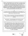
- FIG. 7 is a flow diagram for high-level operation.
- references are given in parentheses to specific disclosed structure/function as an aid to understanding only—these are not meant as limiting the description to the specific referenced items.
- a layered operating stack (e.g., 140 ) is defined that includes a file system layer ( 312 ), a file cache layer ( 400 ), and a unified cache layer ( 402 ).
- the unified cache layer provides a unified cache of data blocks ( 602 ) stored in memory including page descriptors ( 600 ) each capable of referencing a data block stored in either or both the DRAM ( 500 ) or/and the flash ( 502 ) memory.
- the unified cache layer also includes a reference structure ( 508 ) associating file references at the file cache layer with corresponding page descriptors for file data blocks occupying the unified cache.
- Step 702 which includes sub-steps 704 , 706 and 708 , is performed by the unified cache layer. It includes managing use of the memory for caching data blocks of files being written at the file system layer and cached by the file cache layer. The managing includes operations of allocation ( 704 ), access ( 706 ), and eviction/destaging ( 708 ).
- the allocation operation establishes associative references in the reference structure for data blocks upon initial caching.
- the access operation uses the reference structure to locate cached data blocks based on file references.
- the eviction/destaging operation relocates cached data blocks to create room for caching other data blocks, the relocating including a first-level destaging of data blocks from the DRAM to the flash memory at a first time and a second-level destaging of data blocks from the flash memory to the physical storage at a later second time.
- the first-level destaging maintains existing associative references with modification of existing page descriptors to add respective references to the flash memory.
- operating software may be stored on and instantiated from a non-transitory computer-readable medium 710 such as a magnetic or optical disk or nonvolatile semiconductor memory such as flash memory.
- a non-transitory computer-readable medium 710 such as a magnetic or optical disk or nonvolatile semiconductor memory such as flash memory.
- FIGS. 8 and 9 show different deployments of the IO stack 140 .
- a modular deployment is shown in which a first SP 910 houses a front end 142 in a first container 920 and a second SP 930 houses the back end 144 in a second container 940 .
- An interconnection 950 is formed between the first SP 910 and the second SP 930 .
- the interconnection 950 is made using Fibre Channel or some other block-based protocol.
- a parallel arrangement may be formed with a third SP 912 housing a front end 142 in a third container 922 and a fourth SP 932 housing a back end 144 in a fourth container 942 .
- An interconnection 952 is formed between the third SP 912 and the fourth SP 932 .
- performance gains can be realized over the integrated configuration of FIG. 1 , because the modular configuration dedicates the computing and memory resources of multiple SPs to handling host IOs, and because each SP is optimized for operating as a front end or as a back end but is not required to operate as both.
- the first SP 910 , the second SP 930 , the third SP 912 , and fourth SP 932 are physical SPs, any of the SPs housing front ends 142 (SP 1 and SP 3 ) can themselves house any number of virtualized storage processors.
- FIG. 9 shows a gateway arrangement, in which multiple SPs 1010 , 1030 , . . . , 1050 each house a front end 142 in respective containers 1020 , 1040 , . . . , 1060 .
- Interconnections 1022 , 1042 , . . . , 1062 (such as Fibre Channel) respectively connect the SPs 1010 , 1030 , . . . , 1050 to an array 1090 .
- the array 1090 includes its own internal back end, for responding to block-based IOs. Although three SPs are shown providing front ends 142 , it is understood that a greater or lesser number of SPs providing front ends 142 may be provided.
- Suitable examples of the array 1090 include the VMAX® and VPLEX® storage arrays available from EMC Corporation of Hopkinton, Mass.
- An improved technique has been described for a data storage apparatus that combines both block-based and file-based functionality in a unified data path architecture.
- the improved technique brings together IO processing of block-based storage systems and file-based storage systems by expressing both block-based objects and file-based objects in the form of files.
- These files are parts of an underlying, internal set of file systems, which are stored on a set of storage units served by a storage pool. Because block-based and file-based objects are all expressed as files of this set of file systems, a common set of services can be applied across block-based and file-based objects.
- storage units released by any file or files of the underlying, internal set of file systems can be reused by any other file or files, regardless of whether the files represent LUNs, file systems, vVols, and so forth. Inefficiencies of stranded storage are thus greatly reduced or completely eliminated.
- the words “comprising,” “including,” and “having” are intended to set forth certain items, steps, elements, or aspects of something in an open-ended fashion. Although certain embodiments are disclosed herein, it is understood that these are provided by way of example only and the invention is not limited to these particular embodiments. In addition, the word “set” as used herein indicates one or more of something, unless a statement is made to the contrary.
- the lower-deck file systems 230 have been described as storing file representations of LUNs, host file systems, block-based vVols, file-based vVols, and snaps of any of the foregoing. These are merely examples, however.
- Other types of objects may be stored in the lower-deck file systems 230 as file representations, such as virtual hard disks (VHDs), virtual machine disks (VMDKs), internal file systems used by the data storage apparatus 116 , and internal volumes, for example.
- VHDs virtual hard disks
- VMDKs virtual machine disks
- internal file systems used by the data storage apparatus 116 and internal volumes, for example.
- LUNs LUNs, host file systems, etc.
- LUNs LUNs, host file systems, etc.
- files representing different types of objects may be stored in different lower-deck file systems.
- the improvements or portions thereof may be embodied as a non-transient computer-readable storage medium, such as a magnetic disk, magnetic tape, compact disk, DVD, optical disk, flash memory, Application Specific Integrated Circuit (ASIC), Field Programmable Gate Array (FPGA), and the like (shown by way of example as medium 1150 in FIG. 12 ).
- a non-transient computer-readable storage medium such as a magnetic disk, magnetic tape, compact disk, DVD, optical disk, flash memory, Application Specific Integrated Circuit (ASIC), Field Programmable Gate Array (FPGA), and the like (shown by way of example as medium 1150 in FIG. 12 ).
- Multiple computer-readable media may be used.
- the medium (or media) may be encoded with instructions which, when executed on one or more computers or other processors, perform methods that implement the various processes described herein.
- Such medium (or media) may be considered an article of manufacture or a machine, and may be transportable from one machine to another.
Abstract
Description
Claims (20)
Priority Applications (1)
| Application Number | Priority Date | Filing Date | Title |
|---|---|---|---|
| US13/930,164 US9122589B1 (en) | 2013-06-28 | 2013-06-28 | Data storage system with unified system cache |
Applications Claiming Priority (1)
| Application Number | Priority Date | Filing Date | Title |
|---|---|---|---|
| US13/930,164 US9122589B1 (en) | 2013-06-28 | 2013-06-28 | Data storage system with unified system cache |
Publications (1)
| Publication Number | Publication Date |
|---|---|
| US9122589B1 true US9122589B1 (en) | 2015-09-01 |
Family
ID=53938871
Family Applications (1)
| Application Number | Title | Priority Date | Filing Date |
|---|---|---|---|
| US13/930,164 Active 2034-02-06 US9122589B1 (en) | 2013-06-28 | 2013-06-28 | Data storage system with unified system cache |
Country Status (1)
| Country | Link |
|---|---|
| US (1) | US9122589B1 (en) |
Cited By (17)
| Publication number | Priority date | Publication date | Assignee | Title |
|---|---|---|---|---|
| US9645932B1 (en) | 2014-12-19 | 2017-05-09 | EMC IP Holding Company LLC | Persistent metadata cache |
| US9720596B1 (en) | 2014-12-19 | 2017-08-01 | EMC IP Holding Company LLC | Coalescing writes for improved storage utilization |
| US9881016B1 (en) * | 2014-12-31 | 2018-01-30 | EMC IP Holding Company LLC | Unified slice map volume |
| US9916312B1 (en) * | 2014-06-30 | 2018-03-13 | EMC IP Holding Company LLC | Coordination of file system creation to ensure more deterministic performance characteristics |
| US9965201B1 (en) | 2015-03-31 | 2018-05-08 | EMC IP Holding Company LLC | Coalescing file system free space to promote full-stripe writes |
| US20180173435A1 (en) * | 2016-12-21 | 2018-06-21 | EMC IP Holding Company LLC | Method and apparatus for caching data |
| US10055159B2 (en) | 2016-06-20 | 2018-08-21 | Samsung Electronics Co., Ltd. | Morphic storage device |
| US10114829B1 (en) | 2015-06-26 | 2018-10-30 | EMC IP Holding Company LLC | Managing data cache for file system realized within a file |
| CN110413214A (en) * | 2018-04-28 | 2019-11-05 | 伊姆西Ip控股有限责任公司 | Method, equipment and computer program product for storage management |
| US10489076B2 (en) | 2016-06-20 | 2019-11-26 | Samsung Electronics Co., Ltd. | Morphic storage device |
| US10628042B2 (en) * | 2016-01-27 | 2020-04-21 | Bios Corporation | Control device for connecting a host to a storage device |
| US10698831B2 (en) | 2016-12-21 | 2020-06-30 | EMC IP Holding Company LLC | Method and apparatus for data access |
| US11068299B1 (en) | 2017-08-04 | 2021-07-20 | EMC IP Holding Company LLC | Managing file system metadata using persistent cache |
| US11093410B2 (en) | 2017-06-30 | 2021-08-17 | EMC IP Holding Company LLC | Cache management method, storage system and computer program product |
| US20210350031A1 (en) * | 2017-04-17 | 2021-11-11 | EMC IP Holding Company LLC | Method and device for managing storage system |
| US11256439B2 (en) * | 2020-06-30 | 2022-02-22 | EMC IP Holding Company, LLC | System and method for parallel journaling in a storage cluster |
| US11340829B1 (en) * | 2021-03-04 | 2022-05-24 | EMC IP Holding Company LLC | Techniques for log space management involving storing a plurality of page descriptor (PDESC) page block (PB) pairs in the log |
Citations (3)
| Publication number | Priority date | Publication date | Assignee | Title |
|---|---|---|---|---|
| US5809543A (en) * | 1993-12-23 | 1998-09-15 | Unisys Corporation | Fault tolerant extended processing complex for redundant nonvolatile file caching |
| US7814270B2 (en) | 2004-03-12 | 2010-10-12 | Hitachi, Ltd. | Storage systems and methods of controlling cache memory of storage systems |
| US8677062B2 (en) | 2011-05-23 | 2014-03-18 | International Business Machines Corporation | Caching data in a storage system having multiple caches including non-volatile storage cache in a sequential access storage device |
-
2013
- 2013-06-28 US US13/930,164 patent/US9122589B1/en active Active
Patent Citations (3)
| Publication number | Priority date | Publication date | Assignee | Title |
|---|---|---|---|---|
| US5809543A (en) * | 1993-12-23 | 1998-09-15 | Unisys Corporation | Fault tolerant extended processing complex for redundant nonvolatile file caching |
| US7814270B2 (en) | 2004-03-12 | 2010-10-12 | Hitachi, Ltd. | Storage systems and methods of controlling cache memory of storage systems |
| US8677062B2 (en) | 2011-05-23 | 2014-03-18 | International Business Machines Corporation | Caching data in a storage system having multiple caches including non-volatile storage cache in a sequential access storage device |
Cited By (22)
| Publication number | Priority date | Publication date | Assignee | Title |
|---|---|---|---|---|
| US9916312B1 (en) * | 2014-06-30 | 2018-03-13 | EMC IP Holding Company LLC | Coordination of file system creation to ensure more deterministic performance characteristics |
| US9720596B1 (en) | 2014-12-19 | 2017-08-01 | EMC IP Holding Company LLC | Coalescing writes for improved storage utilization |
| US9645932B1 (en) | 2014-12-19 | 2017-05-09 | EMC IP Holding Company LLC | Persistent metadata cache |
| US9881016B1 (en) * | 2014-12-31 | 2018-01-30 | EMC IP Holding Company LLC | Unified slice map volume |
| US9965201B1 (en) | 2015-03-31 | 2018-05-08 | EMC IP Holding Company LLC | Coalescing file system free space to promote full-stripe writes |
| US10114829B1 (en) | 2015-06-26 | 2018-10-30 | EMC IP Holding Company LLC | Managing data cache for file system realized within a file |
| US10628042B2 (en) * | 2016-01-27 | 2020-04-21 | Bios Corporation | Control device for connecting a host to a storage device |
| US10489076B2 (en) | 2016-06-20 | 2019-11-26 | Samsung Electronics Co., Ltd. | Morphic storage device |
| US10055159B2 (en) | 2016-06-20 | 2018-08-21 | Samsung Electronics Co., Ltd. | Morphic storage device |
| US10489075B2 (en) | 2016-06-20 | 2019-11-26 | Samsung Electronics Co., Ltd. | Morphic storage device |
| US20180173435A1 (en) * | 2016-12-21 | 2018-06-21 | EMC IP Holding Company LLC | Method and apparatus for caching data |
| US10496287B2 (en) * | 2016-12-21 | 2019-12-03 | EMC IP Holding Company LLC | Method and apparatus for caching data |
| US10698831B2 (en) | 2016-12-21 | 2020-06-30 | EMC IP Holding Company LLC | Method and apparatus for data access |
| US20210350031A1 (en) * | 2017-04-17 | 2021-11-11 | EMC IP Holding Company LLC | Method and device for managing storage system |
| US11907410B2 (en) * | 2017-04-17 | 2024-02-20 | EMC IP Holding Company LLC | Method and device for managing storage system |
| US11093410B2 (en) | 2017-06-30 | 2021-08-17 | EMC IP Holding Company LLC | Cache management method, storage system and computer program product |
| US11068299B1 (en) | 2017-08-04 | 2021-07-20 | EMC IP Holding Company LLC | Managing file system metadata using persistent cache |
| CN110413214A (en) * | 2018-04-28 | 2019-11-05 | 伊姆西Ip控股有限责任公司 | Method, equipment and computer program product for storage management |
| US10936499B2 (en) | 2018-04-28 | 2021-03-02 | EMC IP Holding Company, LLC | Method, device and computer programme product for storage management |
| CN110413214B (en) * | 2018-04-28 | 2023-07-18 | 伊姆西Ip控股有限责任公司 | Method, apparatus and computer program product for storage management |
| US11256439B2 (en) * | 2020-06-30 | 2022-02-22 | EMC IP Holding Company, LLC | System and method for parallel journaling in a storage cluster |
| US11340829B1 (en) * | 2021-03-04 | 2022-05-24 | EMC IP Holding Company LLC | Techniques for log space management involving storing a plurality of page descriptor (PDESC) page block (PB) pairs in the log |
Similar Documents
| Publication | Publication Date | Title |
|---|---|---|
| US9122589B1 (en) | Data storage system with unified system cache | |
| US9594514B1 (en) | Managing host data placed in a container file system on a data storage array having multiple storage tiers | |
| US9286007B1 (en) | Unified datapath architecture | |
| EP3399444B1 (en) | Optimized record lookups | |
| US9400741B1 (en) | Reclaiming space from file system hosting many primary storage objects and their snapshots | |
| US10346360B1 (en) | Managing prefetching of data in storage systems | |
| US9811276B1 (en) | Archiving memory in memory centric architecture | |
| US10156993B1 (en) | Managing inline data compression in storage systems | |
| US9645932B1 (en) | Persistent metadata cache | |
| US10402096B2 (en) | Unaligned IO cache for inline compression optimization | |
| US9569455B1 (en) | Deduplicating container files | |
| US9652405B1 (en) | Persistence of page access heuristics in a memory centric architecture | |
| US9122697B1 (en) | Unified data services for block and file objects | |
| US8966476B2 (en) | Providing object-level input/output requests between virtual machines to access a storage subsystem | |
| US9454326B1 (en) | File metro cluster for site failover of data storage system | |
| US9959074B1 (en) | Asynchronous in-memory data backup system | |
| US9842117B1 (en) | Managing replication of file systems | |
| US9430480B1 (en) | Active-active metro-cluster scale-out for unified data path architecture | |
| US8856443B2 (en) | Avoiding duplication of data units in a cache memory of a storage system | |
| US20190129971A1 (en) | Storage system and method of controlling storage system | |
| US20050071560A1 (en) | Autonomic block-level hierarchical storage management for storage networks | |
| US9256603B1 (en) | File system over fully provisioned volume file in direct mode | |
| US11625169B2 (en) | Efficient token management in a storage system | |
| JP2012133772A (en) | Data processing method and device for remote storage system | |
| US10089037B1 (en) | Block active/active access to data storage systems at different locations |
Legal Events
| Date | Code | Title | Description |
|---|---|---|---|
| AS | Assignment |
Owner name: EMC CORPORATION, MASSACHUSETTS Free format text: ASSIGNMENT OF ASSIGNORS INTEREST;ASSIGNORS:BONO, JEAN-PIERRE;ARMANGAU, PHILIPPE;HARVEY, DAVID W.;SIGNING DATES FROM 20130712 TO 20130715;REEL/FRAME:030960/0216 |
|
| STCF | Information on status: patent grant |
Free format text: PATENTED CASE |
|
| AS | Assignment |
Owner name: THE BANK OF NEW YORK MELLON TRUST COMPANY, N.A., AS NOTES COLLATERAL AGENT, TEXAS Free format text: SECURITY AGREEMENT;ASSIGNORS:ASAP SOFTWARE EXPRESS, INC.;AVENTAIL LLC;CREDANT TECHNOLOGIES, INC.;AND OTHERS;REEL/FRAME:040136/0001 Effective date: 20160907 Owner name: CREDIT SUISSE AG, CAYMAN ISLANDS BRANCH, AS COLLATERAL AGENT, NORTH CAROLINA Free format text: SECURITY AGREEMENT;ASSIGNORS:ASAP SOFTWARE EXPRESS, INC.;AVENTAIL LLC;CREDANT TECHNOLOGIES, INC.;AND OTHERS;REEL/FRAME:040134/0001 Effective date: 20160907 Owner name: CREDIT SUISSE AG, CAYMAN ISLANDS BRANCH, AS COLLAT Free format text: SECURITY AGREEMENT;ASSIGNORS:ASAP SOFTWARE EXPRESS, INC.;AVENTAIL LLC;CREDANT TECHNOLOGIES, INC.;AND OTHERS;REEL/FRAME:040134/0001 Effective date: 20160907 Owner name: THE BANK OF NEW YORK MELLON TRUST COMPANY, N.A., A Free format text: SECURITY AGREEMENT;ASSIGNORS:ASAP SOFTWARE EXPRESS, INC.;AVENTAIL LLC;CREDANT TECHNOLOGIES, INC.;AND OTHERS;REEL/FRAME:040136/0001 Effective date: 20160907 |
|
| AS | Assignment |
Owner name: EMC IP HOLDING COMPANY LLC, MASSACHUSETTS Free format text: ASSIGNMENT OF ASSIGNORS INTEREST;ASSIGNOR:EMC CORPORATION;REEL/FRAME:040203/0001 Effective date: 20160906 |
|
| MAFP | Maintenance fee payment |
Free format text: PAYMENT OF MAINTENANCE FEE, 4TH YEAR, LARGE ENTITY (ORIGINAL EVENT CODE: M1551); ENTITY STATUS OF PATENT OWNER: LARGE ENTITY Year of fee payment: 4 |
|
| AS | Assignment |
Owner name: THE BANK OF NEW YORK MELLON TRUST COMPANY, N.A., T Free format text: SECURITY AGREEMENT;ASSIGNORS:CREDANT TECHNOLOGIES, INC.;DELL INTERNATIONAL L.L.C.;DELL MARKETING L.P.;AND OTHERS;REEL/FRAME:049452/0223 Effective date: 20190320 Owner name: THE BANK OF NEW YORK MELLON TRUST COMPANY, N.A., TEXAS Free format text: SECURITY AGREEMENT;ASSIGNORS:CREDANT TECHNOLOGIES, INC.;DELL INTERNATIONAL L.L.C.;DELL MARKETING L.P.;AND OTHERS;REEL/FRAME:049452/0223 Effective date: 20190320 |
|
| AS | Assignment |
Owner name: THE BANK OF NEW YORK MELLON TRUST COMPANY, N.A., TEXAS Free format text: SECURITY AGREEMENT;ASSIGNORS:CREDANT TECHNOLOGIES INC.;DELL INTERNATIONAL L.L.C.;DELL MARKETING L.P.;AND OTHERS;REEL/FRAME:053546/0001 Effective date: 20200409 |
|
| AS | Assignment |
Owner name: WYSE TECHNOLOGY L.L.C., CALIFORNIA Free format text: RELEASE BY SECURED PARTY;ASSIGNOR:CREDIT SUISSE AG, CAYMAN ISLANDS BRANCH;REEL/FRAME:058216/0001 Effective date: 20211101 Owner name: SCALEIO LLC, MASSACHUSETTS Free format text: RELEASE BY SECURED PARTY;ASSIGNOR:CREDIT SUISSE AG, CAYMAN ISLANDS BRANCH;REEL/FRAME:058216/0001 Effective date: 20211101 Owner name: MOZY, INC., WASHINGTON Free format text: RELEASE BY SECURED PARTY;ASSIGNOR:CREDIT SUISSE AG, CAYMAN ISLANDS BRANCH;REEL/FRAME:058216/0001 Effective date: 20211101 Owner name: MAGINATICS LLC, CALIFORNIA Free format text: RELEASE BY SECURED PARTY;ASSIGNOR:CREDIT SUISSE AG, CAYMAN ISLANDS BRANCH;REEL/FRAME:058216/0001 Effective date: 20211101 Owner name: FORCE10 NETWORKS, INC., CALIFORNIA Free format text: RELEASE BY SECURED PARTY;ASSIGNOR:CREDIT SUISSE AG, CAYMAN ISLANDS BRANCH;REEL/FRAME:058216/0001 Effective date: 20211101 Owner name: EMC IP HOLDING COMPANY LLC, TEXAS Free format text: RELEASE BY SECURED PARTY;ASSIGNOR:CREDIT SUISSE AG, CAYMAN ISLANDS BRANCH;REEL/FRAME:058216/0001 Effective date: 20211101 Owner name: EMC CORPORATION, MASSACHUSETTS Free format text: RELEASE BY SECURED PARTY;ASSIGNOR:CREDIT SUISSE AG, CAYMAN ISLANDS BRANCH;REEL/FRAME:058216/0001 Effective date: 20211101 Owner name: DELL SYSTEMS CORPORATION, TEXAS Free format text: RELEASE BY SECURED PARTY;ASSIGNOR:CREDIT SUISSE AG, CAYMAN ISLANDS BRANCH;REEL/FRAME:058216/0001 Effective date: 20211101 Owner name: DELL SOFTWARE INC., CALIFORNIA Free format text: RELEASE BY SECURED PARTY;ASSIGNOR:CREDIT SUISSE AG, CAYMAN ISLANDS BRANCH;REEL/FRAME:058216/0001 Effective date: 20211101 Owner name: DELL PRODUCTS L.P., TEXAS Free format text: RELEASE BY SECURED PARTY;ASSIGNOR:CREDIT SUISSE AG, CAYMAN ISLANDS BRANCH;REEL/FRAME:058216/0001 Effective date: 20211101 Owner name: DELL MARKETING L.P., TEXAS Free format text: RELEASE BY SECURED PARTY;ASSIGNOR:CREDIT SUISSE AG, CAYMAN ISLANDS BRANCH;REEL/FRAME:058216/0001 Effective date: 20211101 Owner name: DELL INTERNATIONAL, L.L.C., TEXAS Free format text: RELEASE BY SECURED PARTY;ASSIGNOR:CREDIT SUISSE AG, CAYMAN ISLANDS BRANCH;REEL/FRAME:058216/0001 Effective date: 20211101 Owner name: DELL USA L.P., TEXAS Free format text: RELEASE BY SECURED PARTY;ASSIGNOR:CREDIT SUISSE AG, CAYMAN ISLANDS BRANCH;REEL/FRAME:058216/0001 Effective date: 20211101 Owner name: CREDANT TECHNOLOGIES, INC., TEXAS Free format text: RELEASE BY SECURED PARTY;ASSIGNOR:CREDIT SUISSE AG, CAYMAN ISLANDS BRANCH;REEL/FRAME:058216/0001 Effective date: 20211101 Owner name: AVENTAIL LLC, CALIFORNIA Free format text: RELEASE BY SECURED PARTY;ASSIGNOR:CREDIT SUISSE AG, CAYMAN ISLANDS BRANCH;REEL/FRAME:058216/0001 Effective date: 20211101 Owner name: ASAP SOFTWARE EXPRESS, INC., ILLINOIS Free format text: RELEASE BY SECURED PARTY;ASSIGNOR:CREDIT SUISSE AG, CAYMAN ISLANDS BRANCH;REEL/FRAME:058216/0001 Effective date: 20211101 |
|
| AS | Assignment |
Owner name: SCALEIO LLC, MASSACHUSETTS Free format text: RELEASE OF SECURITY INTEREST IN PATENTS PREVIOUSLY RECORDED AT REEL/FRAME (040136/0001);ASSIGNOR:THE BANK OF NEW YORK MELLON TRUST COMPANY, N.A., AS NOTES COLLATERAL AGENT;REEL/FRAME:061324/0001 Effective date: 20220329 Owner name: EMC IP HOLDING COMPANY LLC (ON BEHALF OF ITSELF AND AS SUCCESSOR-IN-INTEREST TO MOZY, INC.), TEXAS Free format text: RELEASE OF SECURITY INTEREST IN PATENTS PREVIOUSLY RECORDED AT REEL/FRAME (040136/0001);ASSIGNOR:THE BANK OF NEW YORK MELLON TRUST COMPANY, N.A., AS NOTES COLLATERAL AGENT;REEL/FRAME:061324/0001 Effective date: 20220329 Owner name: EMC CORPORATION (ON BEHALF OF ITSELF AND AS SUCCESSOR-IN-INTEREST TO MAGINATICS LLC), MASSACHUSETTS Free format text: RELEASE OF SECURITY INTEREST IN PATENTS PREVIOUSLY RECORDED AT REEL/FRAME (040136/0001);ASSIGNOR:THE BANK OF NEW YORK MELLON TRUST COMPANY, N.A., AS NOTES COLLATERAL AGENT;REEL/FRAME:061324/0001 Effective date: 20220329 Owner name: DELL MARKETING CORPORATION (SUCCESSOR-IN-INTEREST TO FORCE10 NETWORKS, INC. AND WYSE TECHNOLOGY L.L.C.), TEXAS Free format text: RELEASE OF SECURITY INTEREST IN PATENTS PREVIOUSLY RECORDED AT REEL/FRAME (040136/0001);ASSIGNOR:THE BANK OF NEW YORK MELLON TRUST COMPANY, N.A., AS NOTES COLLATERAL AGENT;REEL/FRAME:061324/0001 Effective date: 20220329 Owner name: DELL PRODUCTS L.P., TEXAS Free format text: RELEASE OF SECURITY INTEREST IN PATENTS PREVIOUSLY RECORDED AT REEL/FRAME (040136/0001);ASSIGNOR:THE BANK OF NEW YORK MELLON TRUST COMPANY, N.A., AS NOTES COLLATERAL AGENT;REEL/FRAME:061324/0001 Effective date: 20220329 Owner name: DELL INTERNATIONAL L.L.C., TEXAS Free format text: RELEASE OF SECURITY INTEREST IN PATENTS PREVIOUSLY RECORDED AT REEL/FRAME (040136/0001);ASSIGNOR:THE BANK OF NEW YORK MELLON TRUST COMPANY, N.A., AS NOTES COLLATERAL AGENT;REEL/FRAME:061324/0001 Effective date: 20220329 Owner name: DELL USA L.P., TEXAS Free format text: RELEASE OF SECURITY INTEREST IN PATENTS PREVIOUSLY RECORDED AT REEL/FRAME (040136/0001);ASSIGNOR:THE BANK OF NEW YORK MELLON TRUST COMPANY, N.A., AS NOTES COLLATERAL AGENT;REEL/FRAME:061324/0001 Effective date: 20220329 Owner name: DELL MARKETING L.P. (ON BEHALF OF ITSELF AND AS SUCCESSOR-IN-INTEREST TO CREDANT TECHNOLOGIES, INC.), TEXAS Free format text: RELEASE OF SECURITY INTEREST IN PATENTS PREVIOUSLY RECORDED AT REEL/FRAME (040136/0001);ASSIGNOR:THE BANK OF NEW YORK MELLON TRUST COMPANY, N.A., AS NOTES COLLATERAL AGENT;REEL/FRAME:061324/0001 Effective date: 20220329 Owner name: DELL MARKETING CORPORATION (SUCCESSOR-IN-INTEREST TO ASAP SOFTWARE EXPRESS, INC.), TEXAS Free format text: RELEASE OF SECURITY INTEREST IN PATENTS PREVIOUSLY RECORDED AT REEL/FRAME (040136/0001);ASSIGNOR:THE BANK OF NEW YORK MELLON TRUST COMPANY, N.A., AS NOTES COLLATERAL AGENT;REEL/FRAME:061324/0001 Effective date: 20220329 |
|
| AS | Assignment |
Owner name: SCALEIO LLC, MASSACHUSETTS Free format text: RELEASE OF SECURITY INTEREST IN PATENTS PREVIOUSLY RECORDED AT REEL/FRAME (045455/0001);ASSIGNOR:THE BANK OF NEW YORK MELLON TRUST COMPANY, N.A., AS NOTES COLLATERAL AGENT;REEL/FRAME:061753/0001 Effective date: 20220329 Owner name: EMC IP HOLDING COMPANY LLC (ON BEHALF OF ITSELF AND AS SUCCESSOR-IN-INTEREST TO MOZY, INC.), TEXAS Free format text: RELEASE OF SECURITY INTEREST IN PATENTS PREVIOUSLY RECORDED AT REEL/FRAME (045455/0001);ASSIGNOR:THE BANK OF NEW YORK MELLON TRUST COMPANY, N.A., AS NOTES COLLATERAL AGENT;REEL/FRAME:061753/0001 Effective date: 20220329 Owner name: EMC CORPORATION (ON BEHALF OF ITSELF AND AS SUCCESSOR-IN-INTEREST TO MAGINATICS LLC), MASSACHUSETTS Free format text: RELEASE OF SECURITY INTEREST IN PATENTS PREVIOUSLY RECORDED AT REEL/FRAME (045455/0001);ASSIGNOR:THE BANK OF NEW YORK MELLON TRUST COMPANY, N.A., AS NOTES COLLATERAL AGENT;REEL/FRAME:061753/0001 Effective date: 20220329 Owner name: DELL MARKETING CORPORATION (SUCCESSOR-IN-INTEREST TO FORCE10 NETWORKS, INC. AND WYSE TECHNOLOGY L.L.C.), TEXAS Free format text: RELEASE OF SECURITY INTEREST IN PATENTS PREVIOUSLY RECORDED AT REEL/FRAME (045455/0001);ASSIGNOR:THE BANK OF NEW YORK MELLON TRUST COMPANY, N.A., AS NOTES COLLATERAL AGENT;REEL/FRAME:061753/0001 Effective date: 20220329 Owner name: DELL PRODUCTS L.P., TEXAS Free format text: RELEASE OF SECURITY INTEREST IN PATENTS PREVIOUSLY RECORDED AT REEL/FRAME (045455/0001);ASSIGNOR:THE BANK OF NEW YORK MELLON TRUST COMPANY, N.A., AS NOTES COLLATERAL AGENT;REEL/FRAME:061753/0001 Effective date: 20220329 Owner name: DELL INTERNATIONAL L.L.C., TEXAS Free format text: RELEASE OF SECURITY INTEREST IN PATENTS PREVIOUSLY RECORDED AT REEL/FRAME (045455/0001);ASSIGNOR:THE BANK OF NEW YORK MELLON TRUST COMPANY, N.A., AS NOTES COLLATERAL AGENT;REEL/FRAME:061753/0001 Effective date: 20220329 Owner name: DELL USA L.P., TEXAS Free format text: RELEASE OF SECURITY INTEREST IN PATENTS PREVIOUSLY RECORDED AT REEL/FRAME (045455/0001);ASSIGNOR:THE BANK OF NEW YORK MELLON TRUST COMPANY, N.A., AS NOTES COLLATERAL AGENT;REEL/FRAME:061753/0001 Effective date: 20220329 Owner name: DELL MARKETING L.P. (ON BEHALF OF ITSELF AND AS SUCCESSOR-IN-INTEREST TO CREDANT TECHNOLOGIES, INC.), TEXAS Free format text: RELEASE OF SECURITY INTEREST IN PATENTS PREVIOUSLY RECORDED AT REEL/FRAME (045455/0001);ASSIGNOR:THE BANK OF NEW YORK MELLON TRUST COMPANY, N.A., AS NOTES COLLATERAL AGENT;REEL/FRAME:061753/0001 Effective date: 20220329 Owner name: DELL MARKETING CORPORATION (SUCCESSOR-IN-INTEREST TO ASAP SOFTWARE EXPRESS, INC.), TEXAS Free format text: RELEASE OF SECURITY INTEREST IN PATENTS PREVIOUSLY RECORDED AT REEL/FRAME (045455/0001);ASSIGNOR:THE BANK OF NEW YORK MELLON TRUST COMPANY, N.A., AS NOTES COLLATERAL AGENT;REEL/FRAME:061753/0001 Effective date: 20220329 |
|
| MAFP | Maintenance fee payment |
Free format text: PAYMENT OF MAINTENANCE FEE, 8TH YEAR, LARGE ENTITY (ORIGINAL EVENT CODE: M1552); ENTITY STATUS OF PATENT OWNER: LARGE ENTITY Year of fee payment: 8 |