US9138709B2 - Device and method for dispensing pellets - Google Patents
Device and method for dispensing pellets Download PDFInfo
- Publication number
- US9138709B2 US9138709B2 US13/489,518 US201213489518A US9138709B2 US 9138709 B2 US9138709 B2 US 9138709B2 US 201213489518 A US201213489518 A US 201213489518A US 9138709 B2 US9138709 B2 US 9138709B2
- Authority
- US
- United States
- Prior art keywords
- pellets
- opening
- catalyst
- hopper
- conduit
- Prior art date
- Legal status (The legal status is an assumption and is not a legal conclusion. Google has not performed a legal analysis and makes no representation as to the accuracy of the status listed.)
- Active - Reinstated, expires
Links
- 239000008188 pellet Substances 0.000 title claims abstract description 235
- 238000000034 method Methods 0.000 title claims abstract description 20
- 230000033001 locomotion Effects 0.000 claims description 45
- 230000000284 resting effect Effects 0.000 claims description 21
- 230000015572 biosynthetic process Effects 0.000 claims 4
- 239000003054 catalyst Substances 0.000 description 217
- 238000010410 dusting Methods 0.000 description 13
- 239000000428 dust Substances 0.000 description 9
- 239000002245 particle Substances 0.000 description 8
- 230000008569 process Effects 0.000 description 8
- 125000006850 spacer group Chemical group 0.000 description 6
- 239000000126 substance Substances 0.000 description 6
- 238000006243 chemical reaction Methods 0.000 description 4
- 230000007246 mechanism Effects 0.000 description 4
- 230000007704 transition Effects 0.000 description 4
- 230000008859 change Effects 0.000 description 3
- 239000012530 fluid Substances 0.000 description 3
- 239000000758 substrate Substances 0.000 description 3
- 244000007853 Sarothamnus scoparius Species 0.000 description 2
- 238000005299 abrasion Methods 0.000 description 2
- 230000002708 enhancing effect Effects 0.000 description 2
- 230000005484 gravity Effects 0.000 description 2
- 238000004519 manufacturing process Methods 0.000 description 2
- 239000002184 metal Substances 0.000 description 2
- 230000036961 partial effect Effects 0.000 description 2
- 229910000746 Structural steel Inorganic materials 0.000 description 1
- 230000009471 action Effects 0.000 description 1
- 230000002411 adverse Effects 0.000 description 1
- 239000002826 coolant Substances 0.000 description 1
- 230000003628 erosive effect Effects 0.000 description 1
- 230000002349 favourable effect Effects 0.000 description 1
- 239000006261 foam material Substances 0.000 description 1
- 231100000206 health hazard Toxicity 0.000 description 1
- 239000000463 material Substances 0.000 description 1
- 230000004048 modification Effects 0.000 description 1
- 238000012986 modification Methods 0.000 description 1
- 238000002360 preparation method Methods 0.000 description 1
- 230000002829 reductive effect Effects 0.000 description 1
- 230000001105 regulatory effect Effects 0.000 description 1
- 238000007788 roughening Methods 0.000 description 1
- 238000010408 sweeping Methods 0.000 description 1
- 239000011800 void material Substances 0.000 description 1
Images


Classifications
-
- B—PERFORMING OPERATIONS; TRANSPORTING
- B01—PHYSICAL OR CHEMICAL PROCESSES OR APPARATUS IN GENERAL
- B01J—CHEMICAL OR PHYSICAL PROCESSES, e.g. CATALYSIS OR COLLOID CHEMISTRY; THEIR RELEVANT APPARATUS
- B01J8/00—Chemical or physical processes in general, conducted in the presence of fluids and solid particles; Apparatus for such processes
- B01J8/0015—Feeding of the particles in the reactor; Evacuation of the particles out of the reactor
- B01J8/003—Feeding of the particles in the reactor; Evacuation of the particles out of the reactor in a downward flow
-
- B—PERFORMING OPERATIONS; TRANSPORTING
- B01—PHYSICAL OR CHEMICAL PROCESSES OR APPARATUS IN GENERAL
- B01J—CHEMICAL OR PHYSICAL PROCESSES, e.g. CATALYSIS OR COLLOID CHEMISTRY; THEIR RELEVANT APPARATUS
- B01J8/00—Chemical or physical processes in general, conducted in the presence of fluids and solid particles; Apparatus for such processes
- B01J8/0015—Feeding of the particles in the reactor; Evacuation of the particles out of the reactor
- B01J8/002—Feeding of the particles in the reactor; Evacuation of the particles out of the reactor with a moving instrument
-
- B—PERFORMING OPERATIONS; TRANSPORTING
- B01—PHYSICAL OR CHEMICAL PROCESSES OR APPARATUS IN GENERAL
- B01J—CHEMICAL OR PHYSICAL PROCESSES, e.g. CATALYSIS OR COLLOID CHEMISTRY; THEIR RELEVANT APPARATUS
- B01J8/00—Chemical or physical processes in general, conducted in the presence of fluids and solid particles; Apparatus for such processes
- B01J8/02—Chemical or physical processes in general, conducted in the presence of fluids and solid particles; Apparatus for such processes with stationary particles, e.g. in fixed beds
- B01J8/06—Chemical or physical processes in general, conducted in the presence of fluids and solid particles; Apparatus for such processes with stationary particles, e.g. in fixed beds in tube reactors; the solid particles being arranged in tubes
- B01J8/067—Heating or cooling the reactor
-
- B—PERFORMING OPERATIONS; TRANSPORTING
- B01—PHYSICAL OR CHEMICAL PROCESSES OR APPARATUS IN GENERAL
- B01J—CHEMICAL OR PHYSICAL PROCESSES, e.g. CATALYSIS OR COLLOID CHEMISTRY; THEIR RELEVANT APPARATUS
- B01J2208/00—Processes carried out in the presence of solid particles; Reactors therefor
- B01J2208/00743—Feeding or discharging of solids
- B01J2208/00752—Feeding
Definitions
- the present invention relates to a device and method for dispensing pellets, such as catalyst pellets, to a delivery point, such as into a chemical reactor vessel or into the vertical tubes of a chemical reactor vessel.
- a chemical reactor vessel also can be a simple tank with a single volume of catalyst inside it, or it may be a single large tube. Some chemical reactions occur in furnace or reformer tubes, which may be a part of a system with 10 to 500 or more such tubes.
- catalyst typically in the form of pellets (and other types of pellets that are not catalyst), may be loaded into the reactor to facilitate the reaction. The pellets are replaced periodically.
- the reactor tubes may be quite long, housed in a structure several stories tall, and the pellets may be transported up several stories to an elevation above the top of the tubes so they may then flow by gravity into the tubes.
- the pellets typically are supplied in 2,000 pound (or larger) “super sacks”, 55 gallon drums, mini drums, metal bins or plastic bags loaded in pallet-mounted cardboard boxes.
- each reactor tube there may be several thousand tubes in a single reactor
- Mechanical devices may be used to aid in the dispensing of the pellets.
- a template is placed over a portion of the upper tube sheet.
- the template has openings aligned with the tops of the reactor tubes, with the openings in the templates having a smaller diameter than the inside diameter of the cylindrical reactor tubes in order to restrict the flow of pellets into the reactor tubes to prevent bridging in the tubes.
- Pellets are dumped on top of the template, and operators then use their gloved hands, paddles, brooms, or rakes to spread the pellets back and forth across the template so that pellets fall through the holes in the template and into the respective reactor tubes. Moving the pellets back and forth breaks up any bridging of the pellets above the template, allowing the pellets to flow through the holes in the template and into the reactor tubes.
- loading sleeves are inserted into each reactor tube, with each loading sleeve having a top opening that is smaller than the inside diameter of the cylindrical reactor tube in order to limit the flow of pellets to prevent bridging inside the reactor tubes.
- the pellets are dumped on top of the loading sleeves, and the operators push the pellets back and forth across the loading sleeves so that the pellets fall through the holes in the loading sleeves and into the respective reactor tubes.
- the present invention relates to a device and method for controlled and gentle dispensing of pellets, and does so by breaking up any bridging of the pellets by using a subtle, localized motion that imparts a direct mechanical force to at least one of the pellets adjacent to an opening that is different from the force being applied to the surrounding pellets.
- FIG. 1 is a schematic, section view of a shell and tube type of chemical reactor vessel
- FIG. 2 is a plan view of the upper tube sheet of the reactor of FIG. 1 ;
- FIG. 3 is a broken away, schematic section view of a single reactor tube, tube sheet, and catalyst pellets, showing the pellets bridging across the top opening of the reactor tube;
- FIG. 4 is a broken away, schematic section view, similar to FIG. 3 , but showing a much larger number of catalyst pellets bridging across the top opening of the reactor tube, and illustrates catalyst bridging inside a reactor tube;
- FIG. 5 is a broken away schematic section view, similar to FIG. 4 , but with the addition of a template to aid in the dispensing of the catalyst pellets into the reactor tube;
- FIG. 5A is a broken away schematic section view, similar to FIG. 5 , but using a loading sleeve instead of a template to aid in the dispensing of the catalyst pellets into the reactor tube;
- FIG. 6A is a broken away, schematic plan view of a device for dispensing catalyst mounted over a portion of the template
- FIG. 6B is the same view as 6 A, but with the device shifted to a second position;
- FIG. 6C is the same view as 6 B, but with the device shifted to a third position;
- FIG. 6D is a broken away, plan view of a portion of the catalyst dispensing device of FIG. 6A , showing an alternate configuration for the openings in the dispensing tray;
- FIG. 7 is a broken away schematic section view, similar to that of FIG. 5 , but including the dispensing device of FIG. 6A in the position shown in FIG. 6A , with catalyst pellets bridging above the top of the reactor tube;
- FIG. 8 is the same view as 7 , but showing the dispensing device in the second position, shown in FIG. 6B so as to break the bridging of the catalyst pellets above the top of the reactor tube;
- FIG. 9 is the same view as FIG. 8 , but showing the dispensing device in a third position
- FIG. 10 is a schematic view of a pneumatic control arrangement for the dispensing device of FIGS. 6A-9 ;
- FIG. 11 is a schematic section view of the dispensing tray, taken along line 11 - 11 of FIG. 10 ;
- FIGS. 12A-12H are schematic plan views of some of the possible motions which may be made by the dispensing device of FIG. 10 ;
- FIG. 13 is a broken away, section view of another embodiment of a dispensing device for dispensing catalyst, mounted on an upper tube sheet;
- FIG. 14 is a plan view of the dispensing device of FIG. 13 , with the tube sheet omitted for clarity:
- FIG. 15 is a broken away view, partially in section, of another embodiment of a device for dispensing catalyst
- FIG. 16 is a view taken along line 16 - 16 of FIG. 15 ;
- FIG. 17 is a view taken along line 17 - 17 of FIG. 16 ;
- FIG. 18 is a broken away section view of another embodiment of a dispensing device.
- FIG. 19 is a view taken along line 19 - 19 of FIG. 18 ;
- FIG. 20 is view similar to FIG. 19 , but for another embodiment of a dispensing device
- FIG. 21 is the same view of a dispensing tray as in FIG. 11 but showing an alternate arrangement mounted on a tube sheet and including a spacer between the dispensing device and the tube sheet;
- FIG. 22 is a broken away section view of the tube sheet, similar to FIG. 3 , except showing three tubes, each having a different height relative to the tube sheet;
- FIG. 23 is a side view of dispensing device like that of FIG. 11 or 21 , but including a spacer to accommodate the varying tube heights of FIG. 22 ;
- FIG. 24 is a side view of an alternate embodiment of a catalyst dispensing device, shown in a first, lowered position;
- FIG. 25 is a side view of the dispensing device of FIG. 24 , shown in a second, raised position;
- FIG. 26 is a side view of another alternate embodiment of a catalyst dispensing device, shown in a first position;
- FIG. 27 is a side view of the catalyst dispensing device of FIG. 27 , shown in a second position;
- FIG. 28 is a plan view of an alternate embodiment of a catalyst dispensing device, similar to that of FIG. 26 , but having two bridge breaking wires;
- FIG. 29 is a plan view an alternate embodiment of a catalyst dispensing device, similar to that of FIG. 26 , but for handling multiple tubes simultaneously;
- FIG. 30 is a side view of the catalyst dispensing device of FIG. 29 ;
- FIG. 31 is a side view of another embodiment of a catalyst dispensing device.
- FIG. 32 side view of a bin transport device for the catalyst dispensing device of FIG. 31 ;
- FIG. 33 is a plan view of one the bins of FIG. 31 ;
- FIG. 34 is a side view of the bin of FIG. 33 ;
- FIG. 35A is a side view of the bins of FIG. 31 and the bin transport device of FIG. 32 , in preparation for transferring catalyst into the bins;
- FIG. 35B is a side view, similar to FIG. 35A , but with the bin transport device starting to empty the catalyst into the bins;
- FIG. 35C is a side view, similar to FIG. 35 , but with the catalyst in the bin transport device emptied into the bins;
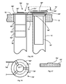
- FIG. 36 is a side view of another embodiment of a catalyst dispensing device.
- FIG. 37 is a view along line 37 - 37 of FIG. 36 ;
- FIG. 38 is a broken away, side view, along line 38 - 38 of FIG. 36 ;
- FIG. 39A is a section view along line 39 A- 39 A of FIG. 38 ;
- FIG. 39B is a section view along line 39 B- 39 B of FIG. 38 ;
- FIG. 40 is a side view, similar to that of FIG. 38 , but with the bridge breaking device in the raised position;
- FIG. 41 is a schematic of the upper portion of the reactor vessel of FIG. 1 when dispensing catalyst into the reactor vessel in the prior art
- FIG. 42 is a schematic, similar to that of FIG. 41 , but when dispensing catalyst into the reactor vessel using an embodiment of a pellet dispensing device made in accordance with the present invention
- FIG. 43 is a more detailed side view of the de-dusting adapter of FIG. 42 ;
- FIG. 44 is a view along line 44 - 44 of FIG. 43 .
- FIG. 1 depicts a typical chemical reactor vessel 10 , which is a shell and tube heat exchanger, having an upper tube sheet 12 and a lower tube sheet 14 with a plurality of vertical tubes 16 welded or expanded to the tube sheets 12 , 14 to form a tightly packed tube bundle.
- Each tube 16 has a top end adjacent the upper tube sheet 12 and a bottom end adjacent the lower tube sheet 14 , and the tubes 16 are open at both ends, except that there may be a clip at the bottom end to retain catalyst pellets inside the tube.
- the upper and lower tube sheets 12 , 14 have openings that are the size of the outside diameter of the tubes 16 , with each tube 16 located in its respective openings in the tube sheets 12 , 14 .
- the vessel 10 includes a top dome (or top head) 13 and a bottom dome (or bottom head) 15 , as well as manways 17 for access to the tube sheets 12 , 14 inside the vessel 10 .
- the manways are closed during operation of the reactor but are opened for access, such as during catalyst handling.
- the tubes 16 are filled with catalyst pellets, which facilitate the chemical reaction.
- similarly-shaped shell and tube heat exchangers may be used for other purposes, such as for a boiler or other heat exchanger.
- This particular reactor vessel 10 is fairly typical. Its tubes may range in length from 5 feet to 65 feet, and it is surrounded by a structural steel skid or framework (not shown), which includes stairways or elevators for access to the tube sheet levels of the reactor vessel 10 as well as access to intermediate levels and to a topmost level which may be located at or near the level of the top opening of the reactor vessel 10 .
- a structural steel skid or framework not shown
- stairways or elevators for access to the tube sheet levels of the reactor vessel 10 as well as access to intermediate levels and to a topmost level which may be located at or near the level of the top opening of the reactor vessel 10 .
- Catalyst handling also may have to be done on an emergency basis, on an unplanned and usually undesirable schedule.
- a catalyst change operation involves a complete shutdown of the reactor, resulting in considerable cost due to lost production.
- the dispensing devices shown and described herein may be used both for the initial loading of a new reactor and for catalyst change operations.) It is desirable to minimize the amount of time required for the catalyst change operation in order to minimize the lost production and accompanying cost caused by the reactor shutdown.
- FIG. 2 is a schematic plan view of the upper tube sheet 12 of FIG. 1 , including a plurality of reactor tubes 16 (and is identical to the lower tube sheet 14 ).
- catalyst pellets 18 may bridge over the open top end of the reactor tube 16 when trying to load catalyst into the reactor tube 16 , which prevents the pellets from entering into the reactor tube 16 . This occurs when the inside diameter of the open top end of the reactor tube 16 is less than about four times the diameter of the pellets.
- FIG. 4 shows that the bridging situation is exacerbated as more catalyst pellets 18 are dumped on top of the tube sheet 12 .
- the conditions are favorable for forming a bridge inside the reactor tube 16 , as shown in FIG. 4 , which creates a void or space below the bridged catalyst inside the tube 16 , preventing the catalyst from completely filling the reactor tube 16 and resulting in a non-uniform and undesirable catalyst loading of the reactor tube 16 .
- prior art devices have relied on templates 20 (as shown in FIG. 5 ) or loading sleeves 22 (as shown in FIG. 5A ) which have smaller openings 34 (in FIG. 5) and 23 (in FIG. 5A ) than the reactor tubes 16 and thereby restrict the flow of pellets 18 into the reactor tubes 16 so as to prevent bridging inside the tube 16 .
- the catalyst pellets 18 still form natural bridges atop the template 20 or atop the loading sleeve 22 .
- FIGS. 6A-D and 7 - 10 show an arrangement including a first embodiment of a catalyst dispensing device 24 for loading catalyst into reactor tubes.
- the dispensing device 24 rests on top of a template 20 , which rests on top of the upper tube sheet 12 of the reactor 10 .
- On the right side of FIG. 6A are shown some of the openings 34 in the template 20 , and, behind them in phantom are the open-top reactor tubes 16 . While the drawing shows only some of those openings 34 and tubes 16 , it is understood that the openings 34 and tubes 16 are distributed evenly throughout the template 20 and the upper tube sheet 12 , respectively. (This may be better understood by looking at FIG.
- the template 20 is a relatively thin plate body having horizontal, planar top and bottom surfaces and defining a plurality of holes extending from the top surface to the bottom surface.
- the bottom surface of the template 20 rests on top of the upper tube sheet 12 and may cover all or a portion of the upper tube sheet 12 .
- the catalyst dispensing device 24 includes a tray 26 , which serves as a hopper and is operatively connected, via connecting rods 28 and pivots 30 (pivot locations are located on the rod end and cap end of their respective cylinders), to four linear-motion drives 32 , which are fixed in position by means of pins 33 , which extend into reactor tubes 16 , as shown in FIGS. 7-9 . (They could extend into other openings in the tube sheet 12 or in the template 20 , or be secured in position by other means, if desired.)
- the double headed arrows 31 indicate the direction of motion of the linear-motion drives 32 .
- each connecting rod 28 allows for misalignment in the connection between the linear-motion drives 32 and the tray 26 to permit the desired motion of the tray 26 .
- the tray 26 moves substantially horizontally, along a plane which is parallel to the plane of the template 20 on which the tray 26 rests.
- the tray 26 includes means for holding a plurality of pellets and has a plurality of openings 36 through which the pellets must pass in order to flow from the tray into the respective vertical reactor tubes 16 .
- the pellets also must pass through the openings 34 in the template 20 located below the tray 26 in order to flow into the respective reactor tubes 16 .
- openings 36 are evenly distributed over the entire tray 26 .
- the catalyst dispensing device 24 may rest on top of the flanges 21 of a plurality of loading sleeves 22 (See FIG. 5A ) instead of resting on top of the template 20 . In that case, then the pellets also would pass through the openings 23 in the loading sleeves in order to flow into the respective reactor tubes 16 .
- the tray 26 of the catalyst dispensing device 24 is resting on top of the template 20 .
- the openings 36 through the tray 26 are a bit larger than the corresponding openings 34 in the template 20 , which permits the tray 26 to shift horizontally relative to the stationary template 20 without closing off any portion of the openings 34 in the template 20 .
- the openings 36 of the tray 26 are axially aligned with the openings 34 in the template 20 , which, in turn, are axially aligned with the respective longitudinal axes of the reactor tubes 16 .
- the template 20 lies between the tray 26 and the tube sheet 12 . Some of the pellets 18 that are forming a bridge are in contact with the top surface of the template 20 .
- the tray 26 has been shifted to the left, so the axes of the openings 36 in the tray 26 are to the left of the axes of their respective template openings 34 and reactor tubes 16 .
- This position is achieved by the linear-motion drives 32 on the right hand side of the catalyst dispensing device 24 (as seen from the vantage point of FIGS. 6A-C ) pushing the tray 26 to the left.
- This causes the vertical edge of the opening 36 in the tray 26 to contact the pellet 18 A, which is resting on the top surface of the template 20 and push it to the left, into the opening 34 of the template 20 , so that pellet 18 A falls through the openings 36 and 34 and into the reactor tube 16 . Since the pellet 18 A was supporting the bridge adjacent to the opening 36 , its movement relative to the other pellets 18 causes the bridge to fall and allows other pellets 18 to fall through the openings 36 , 34 into the reactor tube 16 until another bridge is formed adjacent to the opening 36 .
- FIG. 7 it can be seen in FIG. 7 that a bridge has been formed above the reactor tube 16 , and some of the catalyst pellets 18 are resting on the template 20 inside the opening 36 of the tray 26 .
- the edge of the opening 36 of the tray contacts one or more of those pellets 18 A, shifting them to the left as well, which breaks up the bridge and allows pellets 18 to fall through the opening 36 in the tray and through the opening 34 in the template 20 into the reactor tube 16 until another bridge forms adjacent to the opening 36 in the tray 26 .
- This movement of the tray 26 relative to the template 20 continues to push the supporting pellets out from under the bridge of pellets that they are supporting, thereby breaking up the bridges and allowing the pellets to flow into the reactor tubes 16 without causing any more jarring or abrading of the pellets than is needed to break up the bridging and allow the pellets to flow through the tray 26 into the reactor tubes 16 .
- FIGS. 12A-12H schematically depict some of the different paths which may be traced out by the tray 26 , ranging from a circular clockwise orbit ( FIG. 12A ); a circular counter-clockwise orbit ( FIG. 12B ); quarter circle turns (ninety degrees) alternating clockwise and counterclockwise ( FIG. 12C ); shorter arcuate turns (such as 45 degrees) alternating clockwise and counterclockwise ( FIG. 12D ); quarter oval-shaped turns alternating clockwise and counterclockwise ( FIG. 12E ); rectangular orbits ( FIG. 12F ); star-shaped orbits ( FIG. 12G ); and hexagonal-shaped orbits ( FIG. 12H ).
- FIG. 6D depicts an alternate shape for the opening 36 ′ in the tray 26 ′ of the dispensing device 24 ′, showing that these openings 36 ′ need not be round (as shown in FIGS. 6A-6C ) nor do they have to correspond on a one-to-one basis with the openings 34 in the template 20 (or in the loading sleeve 22 ).
- the openings 36 ′ are almost triangular in shape, with each opening 36 ′ of the tray 26 ′ opening into three openings 34 in the template 20 .
- the control system described in FIG. 10 involves driving the dispensing device 24 pneumatically. It includes four linear-motion pneumatic drives 32 , each one connected to the tray 26 via its corresponding connecting rod 28 .
- a pivot 30 at each end of each connecting rod 28 ensures that the connection point at the tray 26 may be misaligned from the connection point at the linear-motion drive 32 so as to permit the desired motion of the tray 26 .
- a source 40 of pressurized gas (such as compressed air) is in fluid communication, through piping 42 , 44 , with two multi-port solenoid valves 46 , 48 .
- Each solenoid valve 46 , 48 is in turn in fluid communication with two linear-motion pneumatic drives 32 through a set of four flow control devices as described in more detail below.
- the operation of the control scheme for the catalyst dispensing device 24 of FIG. 10 is described below with respect to one linear-motion drive 32 only, on the upper left hand corner of FIG. 10 . It will be clear that the other drives 32 operate in essentially the same manner.
- the air source 40 provides compressed gas to the solenoid valve 46 via the line 42 .
- the solenoid valve 46 sends the compressed air via the path 50 to the line 52 and through the flow control limiter 54 to the linear-motion drive 32 which pushes the connecting rod 28 outwardly (in the down direction as seen from the vantage point of FIG. 10 ).
- the air is exhausted through the flow control limiter 56 and through the line 58 back to the solenoid valve 46 which exhausts the air through the path 60 .
- a proximity switch 62 on the linear-motion drive 32 sends a signal to a controller (not shown) when the linear-motion drive 32 has reached the end of its run.
- the controller actuates the solenoid valve 46 , causing it to shift to a second position (not shown), which reverses the flow of compressed air to retract the connecting rod 28 on the linear-motion drive 32 .
- the proximity switch 62 on the linear-motion drive 32 again sends a signal to the controller when the linear-motion drive 32 has once again reached the end of its run.
- the controller actuates the solenoid valve 46 which shifts and again reverses the flow of compressed air, and the entire cycle is repeated.
- the catalyst dispensing device 24 is placed atop a template 20 wherein the through openings 34 on the template 20 are substantially axially aligned with the reactor tubes 16 .
- the linear-motion drives 32 of the catalyst dispensing device 24 are secured to the template 20 or to the tube sheet 12 to prevent any relative movement between the linear-motion drives 32 and the template 20 .
- Catalyst pellets 18 are dumped into the tray (hopper) area 26 of the catalyst dispensing device 24 which is then powered up to begin the catalyst dispensing process.
- the relative horizontal motion between the tray 26 and the template 20 breaks any bridges as they form, allowing the catalyst pellets 18 to fall through the respective upper opening 36 in the tray 26 and lower opening 34 in the template 20 and into the reactor tubes 16 , as shown in FIGS. 6A-9 .
- the catalyst dispensing device 24 may rest on top of the flanges 21 of a plurality of loading sleeves 22 (see FIG. 5A ) instead of resting on top of the template 20 , in which case the operation would be the same.
- the tray 24 and the underlying substrate (such as the surface of the template 20 or the surface of the flange of the loading sleeve 22 ) that imparts a direct mechanical force to at least one of the pellets 18 adjacent to the opening 36 that is different from the forces being applied to the other surrounding pellets 18 in order to break up the bridging adjacent to the opening 36 , allowing catalyst pellets 18 to fall out of the tray 26 , through the openings 36 and 34 , and into the reactor tube 16 .
- This process continues repeatedly, with successive bridge forming followed by bridge breaking to load the reactor tube 16 with catalyst pellets 18 .
- the reactor tube 16 also serves as a conduit to direct the pellets to the desired delivery point.
- FIGS. 13 and 14 show another embodiment of a catalyst dispensing device 70 . Comparing this catalyst dispensing device 70 in FIG. 13 with the loading sleeve 22 of FIG. 5A , it may be seen that they are quite similar. The most obvious difference is that the catalyst dispensing device 70 is mechanically driven by a drive 72 via a belt 74 .
- the drive 72 may be a rotary or articulating drive, and the belt 74 is a means for transferring the motion of the drive 72 to the loading sleeve 76 of the catalyst dispensing device 70 , as best seen in FIG. 14 .
- This means for transferring the motion of the drive 72 to the loading sleeve 76 may be accomplished by a variety of other means (not shown) such as a gear or a rod.
- ridges 78 on the top surface of the flange 80 of the loading sleeve 76 .
- This embodiment shows two ridges 78 (See FIG. 14 ) which extend radially from the opening 77 to the outer edge of the flange 80 and which are diametrically opposed from each other. While the ridges 78 are preferred, the flange 80 may have a roughened surface or other high friction surface that will cause a pellet 18 that is resting on the top surface of the flange 80 to move along with the flange 80 .
- the loading sleeve may have one or more such ridges 78 , 78 *, as described in more detail later.
- the ridges 78 , 78 * serve to enhance the frictional resistance between the flange 80 of the loading sleeve 76 and the catalyst pellets resting atop the flange 80 of the loading sleeve 76 , such that the mechanical motion imparted by the drive 72 to the loading sleeve 76 is more readily transmitted to the catalyst pellets resting atop the flange 80 so as to promote the breaking of any catalyst bridge.
- the drive 72 imparts a rotary motion to the loading sleeve 76 of the catalyst dispensing device 70 , causing the flange 80 of the loading sleeve 76 to rotate in a horizontal plane, parallel to the top of the tube sheet 12 , rotating slowly about its longitudinal axis, which is a vertical axis, aligned with the vertical axis of the reactor tube 16 .
- the catalyst pellets 18 resting directly on top of the flange 80 travel with the flange 80 , so the flange 80 imparts a direct mechanical force to the pellets 18 resting on top of it, causing them to move relative to the other surrounding pellets 18 above them, which breaks up any catalyst bridges that may form just above the reactor tube 16 .
- the tube sheet 12 and the wall of the reactor vessel serve as a hopper to provide means for holding a plurality of pellets above the vertical reactor tube 16 .
- the opening 77 in the flange 80 has a smaller diameter than the inside diameter of the reactor tube 16 , and the pellets pass through the opening 77 to flow through from the holding means into the reactor tube 16 .
- FIGS. 15-17 depict yet another embodiment of a catalyst dispensing device 70 *. This is similar to the catalyst dispensing device 70 of FIGS. 13 and 14 , except that the drive 72 * is anchored and substantially enclosed by an adjacent reactor tube 16 .
- the drive 72 * includes a battery 82 *, a motor 84 *, and a gearbox 86 *, all of which are suspended inside a reactor tube 16 by the flange 88 * which rests atop the tube sheet 12 .
- a pulley 90 * is engaged by the belt 74 * which in turn engages and drives a similar pulley 92 * on the loading sleeve 76 *.
- the loading sleeve 76 * includes a bearing housing 94 * and a bearing 96 * to minimize frictional resistance to rotation of the loading sleeve 76 * in the reactor tube 16 .
- the flange 80 * on the loading sleeve 76 * defines a plurality of ridges 78 * (See also FIGS. 16 and 17 ).
- the flange 80 * imparts a direct mechanical force to the pellets resting on it, causing those pellets to shift relative to the rest of the pellets in the bridge, and thereby breaking up any bridging of pellets adjacent to the opening 77 * in the flange 80 * so the pellets 18 can flow through the opening 77 * and into the reactor tube 16 .
- FIG. 18 depicts yet another embodiment of a catalyst dispensing device 70 **.
- the catalyst dispensing device 70 ** includes two loading sleeves 76 ** (though one or more such loading sleeves 76 ** may be present) which are similar to the loading sleeve 76 of FIGS. 13 and 14 in that they includes ridges 78 **.
- This catalyst dispensing device 70 ** rests on top of an elevated stationary template or frame 98 ** which has a top surface that lies on a plane which is parallel to the plane of the top surface of the tube sheet 12 , but which provides some clearance between the frame 98 ** and the tube sheet 12 .
- the loading sleeve 76 ** has its flange portion 80 ** resting on top of the frame 98 **, while its tubular “leg” portion 100 ** extends through the frame 98 **, through the space between the frame 98 ** and the tube sheet 12 , through the tube sheet 12 , and into the reactor tube 16 .
- the flange 80 ** defines an opening 23 ** that has a smaller diameter than the inside diameter of the reactor tube 16 , again in order to regulate the flow of catalyst particles into the reactor tube 16 to prevent bridging within the tube 16 .
- blades 102 ** (See also FIG. 19 ), similar to the blades of a blower fan.
- a compressed air nozzle 104 ** is mounted to the frame 98 **. As seen in FIG. 19 , as the compressed air from the air nozzle 104 ** blows on the blades 102 ** of the loading sleeve 76 **, it applies a force causing the loading sleeve 76 ** to rotate in the direction of the arrow 106 .
- the compressed air from the air nozzle 104 ** may blow continuously or it may blow intermittently to cause the loading sleeve 76 ** to spin about its longitudinal axis, and as it does so, it imparts a direct mechanical force to the pellets 18 resting on top of the flange 80 ** of the loading sleeve 76 ** which moves the catalyst pellets 18 resting directly atop the flange 80 ** relative to other pellets 18 that may be forming a bridge adjacent to the opening 23 ** in the flange 80 ** to break up any catalyst bridges, allowing catalyst to fall through the opening 23 ** in the loading sleeve 76 **.
- FIG. 18 also shows a funnel-like container or hopper 108 ** directly above the loading sleeve 76 **, which provides means for holding a plurality of pellets 18 .
- This container 108 ** may include a mark 110 ** corresponding to a preset volumetric dispensing of catalyst inside a reactor tube.
- the funnel-like container 108 ** does not rotate with the loading sleeve 76 **, but remains stationary, resting on the stationary frame 98 **.
- This embodiment may be particularly useful for partial loading of reactor tubes, such as when reactor tubes are loaded with different types of catalyst to different heights within the reactor tubes.
- FIG. 20 is a view similar to FIG. 19 , but for yet another embodiment of a catalyst dispensing device.
- This catalyst dispensing device is essentially identical to the catalyst dispensing device 70 ** of FIG. 18 , except that it has a different mechanism for rotating the loading sleeve 76 ′.
- the loading sleeve 76 ′ is rotated by means of a drive (not shown) similar to the drive 72 of FIGS. 13 and 14 , via a belt 74 ′ and a pulley 75 ′.
- a drive similar to the drive 72 of FIGS. 13 and 14
- a belt 74 ′ and a pulley 75 ′ may be used instead of a belt.
- Each loading sleeve 76 ** in FIG. 18 may be individually driven, or several may be tied together to a common drive.
- the belt 74 ′ in FIG. 20 may wind over a number of pulleys 75 ′ of different loading sleeves 76 ′.
- the air nozzle 104 ** may be fed by a common compressed air line manifold which supplies air to a plurality of air nozzles which blow air on other catalyst dispensing devices 70 **.
- top tube sheet 12 in a reactor vessel is not completely flat. Sometimes it is very slightly domed and often, as shown in FIG. 22 , the reactor tubes 16 project upwardly beyond the top tube sheet 12 , with some tubes projecting upwardly more than other tubes. In FIG. 22 , the upper portion 16 A projects upwardly more than the upper portion 16 b . Some tubes may have a plug 114 secured to the top portion, as shown with the top portion 16 c , which causes the tube to project even a greater distance above the tube sheet 12 .
- FIG. 21 shows a solution to the problem of an uneven tube sheet 12 , whether because the tube sheet 12 is slightly domed or because the tubes 16 project upwardly and unevenly from the tube sheet 12 .
- a spacer 112 is installed between the tube sheet 12 and the template 20 (or it could be between the tube sheet 12 and the loading sleeves 22 of FIG. 5A ).
- This spacer 112 is preferably made of a foam material which adapts its shape to conform to the dome shape of the tube sheet 12 .
- the spacer 112 has through openings 116 which are aligned with the reactor tubes 16 in the tube sheet 12 . These openings 116 are large enough to accommodate any tube projections above the tube sheet 12 such that the top surface 118 of the spacer 112 is substantially flat despite any unevenness in the tube sheet 12 and its reactor tubes 16 .
- FIG. 23 shows an alternate solution to the problem of an uneven tube sheet 12 .
- the template 20 is supported above the tube sheet 12 via a plurality of legs 120 , with the openings 34 in the template 20 substantially vertically aligned with the top openings of the reactor tubes 16 .
- FIGS. 24 and 25 show another embodiment of a catalyst dispensing device 122 .
- This catalyst dispensing device 122 is similar to a loading sleeve, such as the loading sleeve 22 of FIG. 5A in that it includes tubular vertical leg 124 , a portion of which slides into the top of a reactor tube 16 . It also includes a flange 126 which supports the catalyst dispensing device 122 on the top surface of the tube sheet 12 , and it has a through opening 128 at the top of the vertical leg 124 with a small enough diameter to restrict the flow of catalyst particles into the vertical leg 124 and into the reactor tube 16 so as to prevent possible bridging inside the vertical leg 124 and the reactor tube 16 .
- the catalyst dispensing device 122 includes a funnel shaped container 129 which provides means for holding a plurality of pellets above the reactor tube.
- This funnel 129 is attached to, and supported by, the vertical leg (or conduit) 124 of the loading sleeve by a plurality of arched stringers 130 .
- This arrangement allows a narrow annular clearance 136 between the top edge 134 of the vertical leg 124 and the bottom opening 136 of the funnel 129 , which is just wide enough for a movable sleeve 132 to fit between the vertical leg 124 and the funnel 129 and to shift up and down, as explained in more detail below.
- the movable sleeve 132 has an inside diameter which is just slightly larger than the outside diameter of the vertical leg 124 of the loading sleeve and an outside diameter that is just slightly smaller than the inside diameter of the bottom edge 137 (See FIG. 24 ) of the funnel 129 .
- a lower stop band 138 is secured to the outside surface of the vertical leg 124 to provide a lower stop for the movable sleeve 132 , as shown in FIG. 24 .
- An upper stop band 140 is secured to the outside surface of the movable sleeve 132 to provide an upper stop for the movable sleeve 132 , as shown in FIG. 25 , wherein the upper stop band 140 impacts against the bottom of the funnel 129 to stop the movable sleeve 132 at its upper limit.
- the top edge 131 of the movable sleeve 132 is substantially flush with the top edge 134 of the vertical leg 124 .
- the top edge 131 of the movable sleeve 132 projects above the top edge 134 of the vertical leg 124 and into the funnel area itself.
- This slight vertical movement of the movable sleeve 132 relative to the top edge 134 of the vertical leg 124 imparts a direct mechanical force to the pellets 18 adjacent to the opening 128 that is different from forces being applied to the surrounding pellets in order to break up any bridging that may occur within the funnel 129 adjacent to the opening 128 .
- the leg 124 of the loading sleeve is inserted into a reactor tube 16 until the flange 126 is resting on top of the tube sheet 12 .
- the flange 126 may be adjusted vertically along the vertical leg 124 , as desired by loosening the adjustment screw 127 , shifting the flange 126 to the desired position, and then tightening the adjustment screw 127 .
- Catalyst particles (not shown) are added to the funnel 129 , and the movable sleeve 132 is moved up and down to continuously break any bridge forming adjacent to the opening 128 of the loading sleeve.
- the movable sleeve may be moved manually or by some type of automated mechanism as described with respect to the dispensing device 122 * of FIG. 36 . This process continues repeatedly, with successive bridges forming and then followed by bridge breaking to load the reactor tube 16 with catalyst pellets. As is explained below with respect to another embodiment of a catalyst dispensing device 122 * (See FIG. 36 ), the vertical movement of the movable sleeve 132 may be mechanized to automate the dispensing of catalyst into the reactor tubes 16 .
- FIGS. 36-40 show another embodiment of catalyst dispensing device 122 *. It is similar to the catalyst dispensing device 122 of FIG. 24 in that it has a funnel 129 *, a flange 126 *, a vertical leg (or conduit) 124 *, a stop 138 *, and a through opening 128 * (See FIG. 37 ) at the top of the vertical leg 124 * which has a small enough diameter to ensure that the flow of catalyst particles is restricted enough to prevent bridging in the leg 124 * and in the reactor tube 16 .
- the stop 138 * is actually a sleeve or collar which includes a ring 139 * with three upwardly and inwardly projecting prongs 142 *.
- the prongs 142 * are parallel to each other, have their top edges at the same elevation, their bottom edges at the same elevation, and are spaced apart at 120 degree intervals.
- the prongs 142 * ride in grooves 144 * (See FIG. 38 ) in the vertical leg 124 *. These grooves 144 * extend from the top edge 146 * of the vertical leg 124 * downwardly to a distance substantially equal to the height of the prongs 142 *, as seen in FIG. 38 .
- the grooves 144 * lie inside the perimeter of the funnel 129 *, so, as the collar 138 * moves upwardly, the prongs 142 * move up into the interior of the funnel 129 *.
- the collar 138 * can move upwardly until its ring 139 * abuts the outer surface of the funnel 129 *, and it can move downwardly until the bottom surfaces 148 * of the prongs 142 * abut the surfaces 150 * at the bottom of the grooves 144 * (unless the drive mechanism prevents the collar 138 * from reaching its upper and lower limits).
- each prong 142 * projects upwardly into the funnel area.
- This vertical movement of the prongs 142 * of the sleeve 13 * allows the prongs 142 * to impart a direct mechanical force to the pellets 18 adjacent to the opening 128 * that is different from the forces being applied to the surrounding pellets in order to break up any bridging that may occur within the funnel 129 * adjacent to the opening 128 *. Therefore, this catalyst dispensing device 122 * works in a very similar manner to the catalyst dispensing device 122 described earlier.
- FIG. 36 shows an actuator 152 that is fixed relative to the vertical leg 124 * and that is functionally connected to the collar 138 * via a connecting rod 154 .
- the actuator 152 imparts a linear, up-and-down vertical motion to the connecting rod 154 , which, in turn, imparts the same motion to the collar 138 *, as illustrated by the arrow 156 , in order to automate the bridge breaking function of the catalyst dispensing device 122 *.
- FIGS. 26 and 27 show yet another embodiment of a catalyst dispensing device 122 **.
- This catalyst dispensing device 122 * includes a vertical leg (or conduit) 124 ** and a funnel 129 ** which holds the pellets above the reactor tube.
- the top edge 134 ** of the vertical leg 124 ** defines a through opening 128 ** with a smaller diameter than the rest of the leg 124 ** and a smaller diameter than the inside diameter of the reactor tube 16 into which the leg 124 ** is inserted to control the flow rate of pellets in order to prevent bridging in the leg 124 ** and in the reactor tube 16 .
- a rod 156 ** projects through the sides of the funnel 129 ** and extends substantially across and over the opening 128 **.
- the rod 156 ** may be a stiff rod or wire, or it may have some flexibility such as may be obtained by using a thin plastic strip.
- a small enlargement or bump 158 ** is located midway along the length of the rod 156 **.
- the enlargement 158 ** moves across the opening 128 ** and imparts a direct mechanical force to at least one of the pellets adjacent to the opening 128 ** that is different from forces being applied to the other surrounding pellets in order to break up any bridges formed by the catalyst pellets adjacent to the opening 128 **.
- This process continues repeatedly, with successive bridge forming followed by bridge breaking to load the reactor tube with catalyst pellets.
- the rod 156 ** may be moved manually or through an automated, reciprocating mechanism such as a linear actuator that is fixed relative to the leg 124 **.
- FIG. 28 is a plan view of another embodiment of a catalyst dispensing device 122 ′.
- This catalyst dispensing device 122 ′ is identical to the catalyst dispensing device 122 ** described above, except that it has two rods 162 ′, 164 ′ extending through the funnel 129 ′ instead of the single rod 156 ** described earlier. It should be noted that neither of these two rods 162 ′, 164 ′ is located directly above the centerline of the through opening 128 ′ through which the catalyst pellets fall into the reactor tube 16 .
- the rod or rods should be located close enough to the opening 128 ′ to impart a localized, direct mechanical force to at least one of the pellets adjacent to the opening 128 ′ that is different from the forces applied to the other surrounding pellets in order to break the bridges formed adjacent to the opening 128 ′.
- the bumps 158 ** and 158 ′ in the rods are not strictly necessary for proper operation of the catalyst dispensing devices. They provide enhanced contact between the rod and the catalyst pellets and in this manner improve the bridge breaking characteristics of the device. Other means for enhancing the contact with the pellets 18 , such as roughening of the rod itself, may be used for the same end result.
- FIG. 28 further shows a reciprocating rotary actuator 166 used to automate the reciprocating motion of the rods 162 ′, 164 ′ in the direction of the arrow 160 ′.
- the actuator 166 may be used to reciprocate rods connected to a plurality of linearly-aligned catalyst dispensing devices 122 ′.
- FIGS. 29 and 30 show another embodiment of a catalyst dispensing device 122 ′′.
- This catalyst dispensing device 122 ′′ may be described as a hybrid between the catalyst dispensing device 24 of FIG. 6A and the catalyst dispensing device 122 ** of FIG. 26 .
- the catalyst dispensing device 122 ′′ includes a tray (or hopper) 26 ′′ with a plurality of through openings 36 ′′, similar to the tray 26 (See FIG. 11 ) of the catalyst dispensing device 24 .
- the arrow 168 (See FIG. 29 ) indicates the reciprocating motion of the tray 26 ′′ to break any catalyst bridges by the tray 26 ′′ imparting a direct mechanical force to pellets resting on the underlying substrate within the openings 36 ′′ of the tray 26 ′′.
- the underlying substrate is not shown in this view, but has been identified earlier with respect to the description of the catalyst dispensing device 24 , as being either a template or a plurality of loading sleeves.
- a comparison of the tray 26 of FIG. 11 with the tray 26 ′′ of FIGS. 29 and 30 shows the addition of stationary rods 170 with resistance enhancing bumps 172 to the catalyst dispensing device 122 ′′, similar to the rod 156 ** and bump 158 ** of the catalyst dispensing device 122 ** of FIG. 26 .
- the reciprocating motion of the tray 26 ′′ relative to the stationary rods 170 causes the rods 170 to impart a localized, direct mechanical force to the pellets adjacent to the openings 36 ′′ that is different from the forces applied to the surrounding pellets in order to break up catalyst bridges adjacent to the openings 36 ′′.
- FIGS. 31-35 show yet another embodiment of a catalyst dispensing device 122 ⁇ .
- This catalyst dispensing device 122 ⁇ is similar to the catalyst dispensing device 24 of FIG. 6A , but it has several separate bins or hoppers mounted on the dispensing tray 12 ⁇ so a measured load of catalyst pellets 18 is delivered into each reactor tube 16 .
- the catalyst dispensing device 122 ⁇ includes a tray 26 ⁇ with a plurality of openings that are generally aligned with the openings in the top of the reactor tubes 16 . It differs from the embodiment of FIG. 6A in that there are several bins 176 mounted on the tray 26 ⁇ .
- the openings in the tray 26 ⁇ are the same size as and are aligned with the openings 190 in the bottoms of the bins 176 , and the tray 26 ⁇ is thin enough that the openings in the tray are effectively the same as the openings 190 in the bottoms of the bins 176 .
- this embodiment includes a plurality of linear motion drives 32 ⁇ that impart a reciprocating motion to the tray 26 ⁇ (and to the bins 176 that are fixed relative to the tray 26 ⁇ ).
- each dispensing bin 176 is a container having a generally rectangular cross-section with an open top 178 , four side walls 180 , 182 , 184 , and 186 , and a bottom with sloping ramps 188 that directs catalyst pellets to the through opening 190 (which corresponds to the opening 36 in the tray 26 of FIG. 6A ).
- each bin 176 may have an open bottom which matches up directly with its corresponding dispensing plate 174 which is part of the dispensing tray 26 ⁇ , and these dispensing plates 174 that have the sloping ramps 188 direct catalyst pellets to the through openings 190 .
- the cross-section of the dispensing bin 176 is large enough relative to the size of the catalyst pellets that the pellets will not bridge in the bin 176 until they reach the bottom of the bin 176 adjacent the opening 190 . Any bridging in the bin 176 will occur at the very bottom of the bin 176 , just above the opening 190 .
- the reciprocating motion of the tray 26 ⁇ will impart a direct mechanical force to the pellets resting on the template below the tray 26 ⁇ that is different from the force being applied to surrounding pellets, thereby causing relative motion between the pellets forming a bridge so as to break up the bridges and allow the pellets to fall through the openings 190 and into the reactor tubes 16 .
- This catalyst dispensing device 122 ⁇ has a yoke 192 that projects above the bins 176 , as shown in FIGS. 31 and 34 , which assists with dispensing the catalyst pellets into the bins 176 , as will now be described.
- catalyst pellets are delivered in catalyst transport devices 196 , which are open top containers that are adjustably mounted together on a transport bar 198 as shown in FIG. 32 such that their positions along the length of the transport bar 198 may be adjusted to match the location and spacing of the dispensing bins 176 .
- the transport bins 196 may be sized as needed.
- An exact, measured charge or load of catalyst pellets 18 (See FIGS. 35A-35C ) is loaded into each transport bin 196 outside of or adjacent to the reactor prior to the dispensing operation. This charge may be measured by volume, by weight, or by some other desired means.
- the transport bins 196 have marking lines 197 at various elevations, which indicate the various volume charges of pellets that would be loaded into the transport bin 196 if the pellets reached the particular marking line 197 .
- spools 200 mounted on the loading bar 198 , and these spools rest on the yokes 192 of the dispensing bins 176 .
- the spools 200 aid in the proper alignment of the transport bins 196 with the respective dispensing bins 176 and provide a bearing surface to support the transport bins 196 on the yokes 192 .
- a measured charge of catalyst pellets 18 is loaded into each of the transport bins 196 (See FIG. 35A ). This preferably is done outside of the reactor 13 (See FIG. 1 ). A plurality of these catalyst transport bins 196 may be used such that some of them are being loaded while others are being used to transport catalyst to the catalyst dispensing device 122 ⁇ , or the catalyst pellets may be delivered to the site pre-measured and pre-loaded into the transport bins 196 .
- the transport bins 196 may be picked up by the operators and transferred into the reactor vessel 13 through the manhole 17 for fixed head reactors or onto the reactor tube sheet area for removable head reactors either individually or in groups that are already mounted on a transport bar 198 .
- the catalyst transport bins 196 mounted on the transport bar 198 , are moved in the direction of the arrow 204 , and placed onto the catalyst dispensing device 122 ⁇ such that the spools 200 rest on the yokes 192 , which automatically aligns the transport bins 196 with the dispensing bins 176 , as shown in phantom.
- the operators then pivot the transport bar 198 in the direction shown by the arrows 206 , 208 of FIG. 35B until all the catalyst pellets 18 are emptied from the transport bins 196 into their respective dispensing bins 176 , as shown in FIG. 35C .
- the transport bar 198 with attached transport bins 196 is removed and the motion drives 32 ⁇ are powered up to start the reciprocating motion of the tray 26 ⁇ and of the dispensing bins 176 that are fixed to the tray 26 ⁇ .
- the catalyst dispensing device 122 ⁇ is mounted on a template 20 , or on a plurality of loading sleeves 22 , or may even be mounted directly on the tube sheet 12 . If no template or loading sleeves are used, the openings 190 should be small enough to control the flow rate of pellets into the reactor tubes 16 to prevent bridging inside the reactor tubes 16 .
- the reciprocating motion of the catalyst dispensing device 122 ⁇ parallel to the tube sheet or template 20 imparts a localized force to at least one of the pellets resting on the template 20 or loading sleeve 22 or tube sheet 12 that is different from the force being applied to the surrounding pellets in order to break up any bridging in the dispensing bins 176 adjacent to the openings 190 to keep the catalyst pellets 18 flowing into the respective reactor tubes 16 .
- This process continues repeatedly, with successive bridge forming followed by bridge breaking to load the reactor tubes 16 with catalyst pellets 18 .
- the speed of the reciprocating motion of the catalyst dispensing device 122 ⁇ may be adjusted as desired to achieve the desired flow of pellets through the dispensing device 122 ⁇ and into the reactor tubes 16 .
- the reactor tubes may be quite long, housed in a structure several stories tall, and the pellets may be transported up several stories to an elevation above the top of the tubes so they may then flow by gravity into the tubes.
- the pellets typically are supplied in 2,000 pound (or larger) “super sacks”, 55 gallon drums, mini drums, metal bins or plastic bags loaded in pallet-mounted cardboard boxes.
- FIG. 41 is a broken away schematic of the transportation and dispensing of catalyst pellets from a super sack 210 , as practiced in the prior art.
- the super sack 210 is picked up and supported above the reactor vessel 10 by a crane 212 .
- a heavy duty hose 214 (typically a 4 inch to 6 inch diameter hose) is connected to the bottom of the super sack 210 and extends through a top opening 216 in the top flange 218 of the reactor vessel 10 .
- Personnel (not shown) standing on the upper tube sheet 12 of the reactor vessel 10 manually handle the hose 214 inside the reactor vessel 10 to load the catalyst pellets from the super sack 210 onto a template or onto loading sleeves (not shown) placed on top of the upper tube sheet 12 .
- the hose 214 becomes full of catalyst pellets as the operator chokes off the free end of the hose 214 to regulate the flow of catalyst onto the tube sheet 12 .
- the catalyst pellets tend to segregate themselves by size as they come out of the super sack 210 , which prevents consistent loading into the reactor tubes.
- FIGS. 42-44 show a device 220 for dispensing catalyst pellets from a super sack, or from any other container, to a delivery point in the reactor vessel 10 .
- the catalyst dispensing device 220 includes a hopper 222 preferably sized to handle at least all the contents of the container being emptied, such as the 2,000 pounds of catalyst in a super sack.
- This hopper 222 rests atop a funnel-shaped transition piece 224 , which, in turn, connects to a de-dusting adapter 225 , which connects the transition piece 224 to a flexible hose (or conduit) 226 .
- the hose 226 may be a light duty hose, as it is not intended for this hose 226 to be fully loaded with catalyst pellets.
- the light-weight nature of the hose 226 and the fact that it is not loaded up with catalyst pellets makes it easy to move it around to where the catalyst is needed within the reactor.
- a reciprocating plate 228 which is very similar to the bottom of the tray 26 of the catalyst dispensing device 24 of FIG. 6A , including a plurality of through openings and linear motion drive devices 230 , which correspond to the through openings 36 and linear motion drives 32 of FIG. 6A .
- the reciprocating plate (upper plate) 228 lies on top of a second plate (lower plate) 232 .
- This second plate 232 has its own linear motion drive 234 .
- the second plate 232 also defines a plurality of through openings (not shown), each of which substantially aligns with a corresponding opening in the upper reciprocating plate 228 when the second plate 232 is in a first position.
- the second plate 232 moves to a second position, wherein each of the openings on the second plate 232 is in complete misalignment with its corresponding through opening on the reciprocating plate 228 .
- the second plate 232 acts as a positive shut-off valve to interrupt all flow of catalyst pellets from the hopper 222 to the hose or conduit 226 .
- the hopper 222 includes a hinged, watertight cover 236 , which can be opened for bulk dispensing of catalyst pellets as from a super sack.
- a second, smaller cover 238 may be used to load smaller quantities of catalyst pellets (as from small boxes or bags) or for continuous dispensing of catalyst pellets (as through a hose).
- both of these covers 236 , 238 are watertight to allow continued dispensing of catalyst pellets into the reactor vessel 10 even in adverse weather conditions. For instance, one or more super sacks may be emptied into the hopper 222 via the cover 236 while it is not raining. Then, even if it starts to rain, the hopper 222 may be unloaded into the reactor vessel 10 .
- a weather shield 240 may be installed over the de-dusting adapter 225 and the flange connection 218 for further assurance of water-tightness, if required.
- the de-dusting adapter 225 has a cylindrical wall 227 equidistant about an imaginary vertical axis, and that cylindrical wall 227 has an outer surface and an inner surface.
- a nozzle 248 extends horizontally from a large, circular opening 249 in the cylindrical wall 227 .
- the cylindrical wall 227 defines a plurality of radially-arranged slotted openings 242 for admitting air into the interior of the cylinder 227 , as shown by the arrows 244 in FIG. 44 .
- a partial cylindrical baffle wall 246 creates a tortuous path 247 for the air being drawn through the de-dusting adapter 225 to ensure that only lighter-weight dust particles are pulled out of the de-dusting adapter 225 via a vacuum source (not shown) connected to the nozzle 248 projecting from one side of the de-dusting adapter 225 .
- the baffle 246 could be replaced by a fairly tight wire mesh screen which covers the opening 249 into the nozzle 248 , such that only small dust particles are extracted from the de-dusting adapter 225 while larger catalyst pellets are rejected and allowed to fall into the hose 226 .
- the device 220 is first installed onto the top flange 218 of the reactor vessel 10 , as shown in FIG. 42 .
- Pneumatic air is provided for the linear motion drives 230 of the reciprocating plate 228 as well as for the linear motion drive 234 of the second plate (shut-off plate) 232 .
- the hopper 222 is at least partially filled with catalyst pellets, which enter through the large cover 236 or the small cover 238 while the shut-off plate 232 is in the closed position.
- a vacuum source is also connected to the nozzle 248 of the de-dusting adapter 225 .
- the actuator 234 for the shut-off plate 232 may be actuated to open the path, allowing catalyst pellets to fall from the hopper 222 , through openings in both plates 228 , 232 , to the hose 226 . Since the effective diameter of the aligned openings in the upper plate 228 and lower plate 232 are only slightly larger in diameter than the catalyst pellets, only a small amount of pellets will fall through the aligned openings in the plates before bridges of pellets form in the hopper 222 above the respective openings, preventing more catalyst pellets from falling into the hose or conduit 226 .
- the actuators 230 for the reciprocating upper plate 228 may now be actuated to provide localized, direct mechanical force to continuously and gently break the bridges forming in the hopper 222 , allowing the catalyst pellets to fall continuously through the aligned openings in the upper and lower plates 228 , 232 and into the hose 226 .
- the operator directs the free end of the hose 226 as required to deposit the de-dusted catalyst pellets at delivery points where they are needed.
- the operator inside the reactor vessel 10 has direct control of the pneumatic air to the linear motion drive 234 of the shut-off plate 232 in order to stop the flow of catalyst pellets to the upper tube sheet 12 of the reactor vessel 10 .
- the operator also has direct control of the pneumatics to the linear motion drives 230 of the reciprocating plate 228 so he can regulate the frequency of reciprocation of the plate 228 , which regulates the flow of catalyst pellets by regulating the frequency with which the bridges impeding the flow of catalyst pellets are broken.
- the hopper 222 is emptied evenly, gradually, gently, and from the bottom. That is, the catalyst pellets closest to the reciprocating plate 228 are always the first to be drawn out of the hopper 222 .
- a metered flow rate of catalyst pellets controlled by the operator, flows down through the transition piece 224 and through the de-dusting adapter 225 , where the dust generated thus far by the handling of the catalyst pellets is removed, as discussed earlier.
- the de-dusted catalyst pellets proceed down the hose 226 to where the operator wants them to be deposited.
- the flow rate can be controlled by the operator, and the flow of catalyst pellets can be stopped at the bottom of the hopper 222 by the operator (either by stopping the reciprocation of the upper plate 228 or by actuating the actuator 234 for the lower, shut-off plate 232 ), the hose 226 need not ever be full of catalyst pellets. This makes it much easier for the operator to handle the hose 226 , and a lighter weight hose can be used than is the case with the prior art arrangement shown in FIG. 41 .
Abstract
Description
Claims (6)
Priority Applications (4)
| Application Number | Priority Date | Filing Date | Title |
|---|---|---|---|
| US13/489,518 US9138709B2 (en) | 2010-05-24 | 2012-06-06 | Device and method for dispensing pellets |
| US13/848,269 US9149778B2 (en) | 2010-05-24 | 2013-03-21 | Device and method for dispensing catalyst pellets |
| PCT/US2013/042849 WO2013184434A2 (en) | 2012-06-06 | 2013-05-28 | Device and method for dispensing catalyst pellets |
| TW102120201A TW201408364A (en) | 2012-06-06 | 2013-06-06 | Device and method for dispensing catalyst pellets |
Applications Claiming Priority (3)
| Application Number | Priority Date | Filing Date | Title |
|---|---|---|---|
| US34748310P | 2010-05-24 | 2010-05-24 | |
| US13/102,662 US8646492B2 (en) | 2010-05-24 | 2011-05-06 | Device for loading catalyst into a reactor vessel |
| US13/489,518 US9138709B2 (en) | 2010-05-24 | 2012-06-06 | Device and method for dispensing pellets |
Related Parent Applications (1)
| Application Number | Title | Priority Date | Filing Date |
|---|---|---|---|
| US13/102,662 Continuation-In-Part US8646492B2 (en) | 2010-05-24 | 2011-05-06 | Device for loading catalyst into a reactor vessel |
Related Child Applications (1)
| Application Number | Title | Priority Date | Filing Date |
|---|---|---|---|
| US13/848,269 Continuation-In-Part US9149778B2 (en) | 2010-05-24 | 2013-03-21 | Device and method for dispensing catalyst pellets |
Publications (2)
| Publication Number | Publication Date |
|---|---|
| US20130140322A1 US20130140322A1 (en) | 2013-06-06 |
| US9138709B2 true US9138709B2 (en) | 2015-09-22 |
Family
ID=48523272
Family Applications (1)
| Application Number | Title | Priority Date | Filing Date |
|---|---|---|---|
| US13/489,518 Active - Reinstated 2032-11-14 US9138709B2 (en) | 2010-05-24 | 2012-06-06 | Device and method for dispensing pellets |
Country Status (1)
| Country | Link |
|---|---|
| US (1) | US9138709B2 (en) |
Families Citing this family (4)
| Publication number | Priority date | Publication date | Assignee | Title |
|---|---|---|---|---|
| CN106215761A (en) * | 2016-07-25 | 2016-12-14 | 柳州合科技有限公司 | A kind of fodder mixing machine feed arrangement |
| CN106179045A (en) * | 2016-07-25 | 2016-12-07 | 柳州合科技有限公司 | A kind of altofrequency fodder mixing machine feed arrangement |
| CN106166459A (en) * | 2016-07-25 | 2016-11-30 | 柳州合科技有限公司 | A kind of high performance fodder mixing machine feed arrangement |
| JP2020517422A (en) | 2017-04-20 | 2020-06-18 | チューブマスター・インコーポレイテッド | How to load pellets |
Citations (33)
| Publication number | Priority date | Publication date | Assignee | Title |
|---|---|---|---|---|
| US3223490A (en) | 1962-02-09 | 1965-12-14 | Houston Chemical Corp | Catalyst loader and method of filling tubes |
| US3913806A (en) | 1973-11-12 | 1975-10-21 | Browning Ferris Industries | Apparatus for loading flowable material |
| US4402643A (en) | 1981-02-18 | 1983-09-06 | Ppg Industries, Inc. | Catalyst loader |
| US4597946A (en) | 1985-04-30 | 1986-07-01 | Uop Inc. | Vertical tube reactor with serial downward flow through a plurality of sets of particulate containing tubes |
| US4701101A (en) | 1984-03-13 | 1987-10-20 | Catalyst Technology, Inc. | Modular multi-tube catalyst loading funnel |
| DE19539628A1 (en) | 1994-10-21 | 1996-04-25 | Merkle Eng Inc | Supply of granular raw material to a glass furnace |
| US5626455A (en) | 1994-01-27 | 1997-05-06 | Basf Corporation | Ethylene oxide catalyst loading device |
| US6170670B1 (en) | 1997-01-23 | 2001-01-09 | Nippon Shokubai Co., Ltd. | Methods of and apparatus for feeding granular material |
| US6183232B1 (en) | 1996-12-18 | 2001-02-06 | Amsted Industries Incorporated | Raw material delivery system for compacting press |
| US20030194360A1 (en) | 2001-04-10 | 2003-10-16 | Huziwara Wilson Kenzo | Multifunctional entry method and device for downward flow tube reactor |
| US6725706B2 (en) | 2001-03-16 | 2004-04-27 | Tubemaster, Inc. | Device and method for blowing down and measuring the back pressure of chemical reactor tubes |
| US20040146457A1 (en) | 2001-06-06 | 2004-07-29 | Bence Roger Kenneth | Process and apparatus for loading a particulate solid into a vertical tube |
| CN1765481A (en) | 2004-10-29 | 2006-05-03 | 中国石油化工股份有限公司 | Multi-segment insulation fix bed reactor |
| US20070196253A1 (en) | 2004-03-15 | 2007-08-23 | Karl-Heinz Stocksiefen | Device for filling tubes, containers and the like with bulk materials |
| US7285251B2 (en) | 2003-03-28 | 2007-10-23 | Tubemaster Inc. | Tool for loading reactor tubes |
| US20080149215A1 (en) | 2004-08-13 | 2008-06-26 | Total France | Device for Loading a Vessel with Solid Particles and Method Using Said Device |
| US20080193267A1 (en) | 2005-03-24 | 2008-08-14 | Sud-Chemie Ag | Feeding Device for Bundled Tube Reactor |
| US20080302388A1 (en) | 2007-06-08 | 2008-12-11 | Tubemaster, Inc. | Method of cleaning tubes |
| US20090097958A1 (en) | 2007-10-15 | 2009-04-16 | Tubemaster, Inc. | Device and method for transporting catalyst to a reactor vessel |
| US20090095211A1 (en) | 2007-10-11 | 2009-04-16 | Tubemaster, Inc. | Device and method for indicating the condition of tubes on a tubesheet |
| US20090112367A1 (en) | 2007-03-01 | 2009-04-30 | Decourcy Michael Stanley | Apparatus and method for dislodging and extracting solid materials from tubes |
| US20090145727A1 (en) | 2007-12-11 | 2009-06-11 | Tubemaster Inc. | Device and process for precision loading of particles in a vertical tube chemical reactor |
| US20100059137A1 (en) | 2008-09-11 | 2010-03-11 | Tubemaster Inc. | Loading sleeve and method for loading chemical reactor tubes |
| US7765948B2 (en) | 2007-08-07 | 2010-08-03 | Tubemaster, Inc. | Device and method for identifying the row number on a tubesheet |
| US7776288B2 (en) | 2006-03-23 | 2010-08-17 | Süd-Chemie AG | Charging device for a tubular reactor |
| US7836919B2 (en) | 2005-10-03 | 2010-11-23 | Tubemaster Inc. | Device for loading chemical reactor tubes |
| US7861875B2 (en) | 2007-02-02 | 2011-01-04 | Tubemaster, Inc. | Seal for tube |
| US20110020186A1 (en) | 2004-12-30 | 2011-01-27 | Beech Jr James H | Fluidizing A Population of Catalyst Particles Having A Low Catalyst Fines Content |
| US7878225B2 (en) | 2006-12-18 | 2011-02-01 | Tubemaster, Inc. | Vacuum attachment and method |
| US20110083769A1 (en) | 2009-10-01 | 2011-04-14 | IFP Energies Nouvelles | Device for loading particles of catatlyst into tubes having an annular zone |
| US20110277421A1 (en) | 2008-12-10 | 2011-11-17 | Arend Jan Te Raa | Loading Device for Loading Particles, Method for Loading Particles Using a Loading Device |
| US20110283666A1 (en) | 2010-05-24 | 2011-11-24 | Johns Clifford L | Device for loading catalyst into a reactor vessel |
| US20120000761A1 (en) | 2009-03-17 | 2012-01-05 | T.D.E. Recovery Technologies Ltd. | Feeding apparatus and method for a pyrolytic reactor |
-
2012
- 2012-06-06 US US13/489,518 patent/US9138709B2/en active Active - Reinstated
Patent Citations (35)
| Publication number | Priority date | Publication date | Assignee | Title |
|---|---|---|---|---|
| US3223490A (en) | 1962-02-09 | 1965-12-14 | Houston Chemical Corp | Catalyst loader and method of filling tubes |
| US3913806A (en) | 1973-11-12 | 1975-10-21 | Browning Ferris Industries | Apparatus for loading flowable material |
| US4402643A (en) | 1981-02-18 | 1983-09-06 | Ppg Industries, Inc. | Catalyst loader |
| US4701101A (en) | 1984-03-13 | 1987-10-20 | Catalyst Technology, Inc. | Modular multi-tube catalyst loading funnel |
| US4597946A (en) | 1985-04-30 | 1986-07-01 | Uop Inc. | Vertical tube reactor with serial downward flow through a plurality of sets of particulate containing tubes |
| US5626455A (en) | 1994-01-27 | 1997-05-06 | Basf Corporation | Ethylene oxide catalyst loading device |
| DE19539628A1 (en) | 1994-10-21 | 1996-04-25 | Merkle Eng Inc | Supply of granular raw material to a glass furnace |
| US6183232B1 (en) | 1996-12-18 | 2001-02-06 | Amsted Industries Incorporated | Raw material delivery system for compacting press |
| US6170670B1 (en) | 1997-01-23 | 2001-01-09 | Nippon Shokubai Co., Ltd. | Methods of and apparatus for feeding granular material |
| US6725706B2 (en) | 2001-03-16 | 2004-04-27 | Tubemaster, Inc. | Device and method for blowing down and measuring the back pressure of chemical reactor tubes |
| US20030194360A1 (en) | 2001-04-10 | 2003-10-16 | Huziwara Wilson Kenzo | Multifunctional entry method and device for downward flow tube reactor |
| US20040146457A1 (en) | 2001-06-06 | 2004-07-29 | Bence Roger Kenneth | Process and apparatus for loading a particulate solid into a vertical tube |
| US7285251B2 (en) | 2003-03-28 | 2007-10-23 | Tubemaster Inc. | Tool for loading reactor tubes |
| US20070196253A1 (en) | 2004-03-15 | 2007-08-23 | Karl-Heinz Stocksiefen | Device for filling tubes, containers and the like with bulk materials |
| US20080149215A1 (en) | 2004-08-13 | 2008-06-26 | Total France | Device for Loading a Vessel with Solid Particles and Method Using Said Device |
| CN1765481A (en) | 2004-10-29 | 2006-05-03 | 中国石油化工股份有限公司 | Multi-segment insulation fix bed reactor |
| US20110020186A1 (en) | 2004-12-30 | 2011-01-27 | Beech Jr James H | Fluidizing A Population of Catalyst Particles Having A Low Catalyst Fines Content |
| US20080193267A1 (en) | 2005-03-24 | 2008-08-14 | Sud-Chemie Ag | Feeding Device for Bundled Tube Reactor |
| US7897120B2 (en) | 2005-03-24 | 2011-03-01 | Sud-Chemie Ag | Feeding device for bundled tube reactor |
| US7836919B2 (en) | 2005-10-03 | 2010-11-23 | Tubemaster Inc. | Device for loading chemical reactor tubes |
| US7776288B2 (en) | 2006-03-23 | 2010-08-17 | Süd-Chemie AG | Charging device for a tubular reactor |
| US7878225B2 (en) | 2006-12-18 | 2011-02-01 | Tubemaster, Inc. | Vacuum attachment and method |
| US7861875B2 (en) | 2007-02-02 | 2011-01-04 | Tubemaster, Inc. | Seal for tube |
| US20090112367A1 (en) | 2007-03-01 | 2009-04-30 | Decourcy Michael Stanley | Apparatus and method for dislodging and extracting solid materials from tubes |
| US20080302388A1 (en) | 2007-06-08 | 2008-12-11 | Tubemaster, Inc. | Method of cleaning tubes |
| US7765948B2 (en) | 2007-08-07 | 2010-08-03 | Tubemaster, Inc. | Device and method for identifying the row number on a tubesheet |
| US20090095211A1 (en) | 2007-10-11 | 2009-04-16 | Tubemaster, Inc. | Device and method for indicating the condition of tubes on a tubesheet |
| US20090097958A1 (en) | 2007-10-15 | 2009-04-16 | Tubemaster, Inc. | Device and method for transporting catalyst to a reactor vessel |
| US8166811B2 (en) | 2007-12-11 | 2012-05-01 | Extundo Incorporated | Device and process for precision loading of particles in a vertical tube chemical reactor |
| US20090145727A1 (en) | 2007-12-11 | 2009-06-11 | Tubemaster Inc. | Device and process for precision loading of particles in a vertical tube chemical reactor |
| US20100059137A1 (en) | 2008-09-11 | 2010-03-11 | Tubemaster Inc. | Loading sleeve and method for loading chemical reactor tubes |
| US20110277421A1 (en) | 2008-12-10 | 2011-11-17 | Arend Jan Te Raa | Loading Device for Loading Particles, Method for Loading Particles Using a Loading Device |
| US20120000761A1 (en) | 2009-03-17 | 2012-01-05 | T.D.E. Recovery Technologies Ltd. | Feeding apparatus and method for a pyrolytic reactor |
| US20110083769A1 (en) | 2009-10-01 | 2011-04-14 | IFP Energies Nouvelles | Device for loading particles of catatlyst into tubes having an annular zone |
| US20110283666A1 (en) | 2010-05-24 | 2011-11-24 | Johns Clifford L | Device for loading catalyst into a reactor vessel |
Also Published As
| Publication number | Publication date |
|---|---|
| US20130140322A1 (en) | 2013-06-06 |
Similar Documents
| Publication | Publication Date | Title |
|---|---|---|
| US8646492B2 (en) | Device for loading catalyst into a reactor vessel | |
| US9138709B2 (en) | Device and method for dispensing pellets | |
| AU2002309460B2 (en) | Containerised handling of bulk materials and apparatus therefor | |
| US8061524B2 (en) | Device and method for transporting catalyst to a reactor vessel | |
| CN104334267B (en) | particulate material loading device | |
| AU2002309460A1 (en) | Containerised handling of bulk materials and apparatus therefor | |
| CN104129654B (en) | A kind of drum type device for discharging and pneumatic conveying material transmission system thereof | |
| EP1106534A2 (en) | Silo for storing and controlled supply of empty light containers, and method for using such silo | |
| US9149778B2 (en) | Device and method for dispensing catalyst pellets | |
| US20130298507A1 (en) | Device for filling a container with solid particles comprising a diaphragm | |
| US20120298253A1 (en) | Device and Method for Packaging Bulk Material | |
| US20090050446A1 (en) | Method for transporting a particulate material and a transportation device for a particulate material | |
| JP2008534410A (en) | Method for filling a solid with equipment | |
| TWI417235B (en) | An apparatus and method for feeding with continuousness and quantity | |
| US20170296994A1 (en) | Arrangement for Loading Particles | |
| CN207158340U (en) | Solid automatic charging machine | |
| JPS58500756A (en) | Method for conveying powdered materials and equipment for carrying out this method | |
| WO2023031275A1 (en) | A vacuum loader and a method of filling a receptacle using the vacuum loader | |
| RU146375U1 (en) | DEVICE FOR SEALED LOADING OF BULK MATERIALS | |
| RU2661519C2 (en) | Bulk material loading device (variants) | |
| CN205854562U (en) | A kind of packer manufactured for chemical fertilizer | |
| CN210392250U (en) | Dry-mixed mortar finished product bin | |
| WO2013184434A2 (en) | Device and method for dispensing catalyst pellets | |
| JP2007261612A (en) | Bagging apparatus and bagging method for powder/granular material | |
| CN107161725B (en) | A kind of Mobile particle material dress takes conveying device |
Legal Events
| Date | Code | Title | Description |
|---|---|---|---|
| AS | Assignment |
Owner name: EXTUNDO INCORPORATED, KENTUCKY Free format text: ASSIGNMENT OF ASSIGNORS INTEREST;ASSIGNORS:JOHNS, CLIFFORD L;CHASMAWALA, MUNAF;MCANDREWS, DENNIS;REEL/FRAME:028501/0891 Effective date: 20120628 |
|
| ZAAA | Notice of allowance and fees due |
Free format text: ORIGINAL CODE: NOA |
|
| ZAAB | Notice of allowance mailed |
Free format text: ORIGINAL CODE: MN/=. |
|
| STCF | Information on status: patent grant |
Free format text: PATENTED CASE |
|
| MAFP | Maintenance fee payment |
Free format text: PAYMENT OF MAINTENANCE FEE, 4TH YR, SMALL ENTITY (ORIGINAL EVENT CODE: M2551); ENTITY STATUS OF PATENT OWNER: SMALL ENTITY Year of fee payment: 4 |
|
| FEPP | Fee payment procedure |
Free format text: MAINTENANCE FEE REMINDER MAILED (ORIGINAL EVENT CODE: REM.); ENTITY STATUS OF PATENT OWNER: SMALL ENTITY |
|
| LAPS | Lapse for failure to pay maintenance fees |
Free format text: PATENT EXPIRED FOR FAILURE TO PAY MAINTENANCE FEES (ORIGINAL EVENT CODE: EXP.); ENTITY STATUS OF PATENT OWNER: SMALL ENTITY |
|
| STCH | Information on status: patent discontinuation |
Free format text: PATENT EXPIRED DUE TO NONPAYMENT OF MAINTENANCE FEES UNDER 37 CFR 1.362 |
|
| FP | Lapsed due to failure to pay maintenance fee |
Effective date: 20230922 |
|
| FEPP | Fee payment procedure |
Free format text: PETITION RELATED TO MAINTENANCE FEES FILED (ORIGINAL EVENT CODE: PMFP); ENTITY STATUS OF PATENT OWNER: SMALL ENTITY Free format text: PETITION RELATED TO MAINTENANCE FEES GRANTED (ORIGINAL EVENT CODE: PMFG); ENTITY STATUS OF PATENT OWNER: SMALL ENTITY Free format text: SURCHARGE, PETITION TO ACCEPT PYMT AFTER EXP, UNINTENTIONAL. (ORIGINAL EVENT CODE: M2558); ENTITY STATUS OF PATENT OWNER: SMALL ENTITY |
|
| MAFP | Maintenance fee payment |
Free format text: PAYMENT OF MAINTENANCE FEE, 8TH YR, SMALL ENTITY (ORIGINAL EVENT CODE: M2552); ENTITY STATUS OF PATENT OWNER: SMALL ENTITY Year of fee payment: 8 |
|
| STCF | Information on status: patent grant |
Free format text: PATENTED CASE |