US9140873B2 - System and method for compensating for distortions in optical fibers - Google Patents
System and method for compensating for distortions in optical fibers Download PDFInfo
- Publication number
- US9140873B2 US9140873B2 US14/307,338 US201414307338A US9140873B2 US 9140873 B2 US9140873 B2 US 9140873B2 US 201414307338 A US201414307338 A US 201414307338A US 9140873 B2 US9140873 B2 US 9140873B2
- Authority
- US
- United States
- Prior art keywords
- fiber
- core
- segment
- index
- core region
- Prior art date
- Legal status (The legal status is an assumption and is not a legal conclusion. Google has not performed a legal analysis and makes no representation as to the accuracy of the status listed.)
- Expired - Fee Related
Links
- 238000000034 method Methods 0.000 title claims abstract description 67
- 239000013307 optical fiber Substances 0.000 title claims abstract description 40
- 238000005253 cladding Methods 0.000 claims abstract description 101
- 238000001914 filtration Methods 0.000 claims description 66
- 229910052761 rare earth metal Inorganic materials 0.000 claims description 33
- 239000000203 mixture Substances 0.000 claims description 5
- 230000002269 spontaneous effect Effects 0.000 claims description 4
- 230000002238 attenuated effect Effects 0.000 claims 2
- 239000000835 fiber Substances 0.000 abstract description 586
- 238000005452 bending Methods 0.000 abstract description 52
- 238000013461 design Methods 0.000 description 56
- 230000000116 mitigating effect Effects 0.000 description 38
- 238000010586 diagram Methods 0.000 description 33
- 239000011521 glass Substances 0.000 description 29
- 150000002910 rare earth metals Chemical class 0.000 description 28
- 239000002019 doping agent Substances 0.000 description 25
- 239000004038 photonic crystal Substances 0.000 description 17
- 230000007704 transition Effects 0.000 description 14
- 230000003247 decreasing effect Effects 0.000 description 12
- 238000012546 transfer Methods 0.000 description 11
- 241000894007 species Species 0.000 description 10
- 230000003287 optical effect Effects 0.000 description 9
- 230000003321 amplification Effects 0.000 description 8
- 238000001816 cooling Methods 0.000 description 8
- 230000007423 decrease Effects 0.000 description 8
- 238000004519 manufacturing process Methods 0.000 description 8
- 238000003199 nucleic acid amplification method Methods 0.000 description 8
- 230000008878 coupling Effects 0.000 description 7
- 238000010168 coupling process Methods 0.000 description 7
- 238000005859 coupling reaction Methods 0.000 description 7
- 239000007787 solid Substances 0.000 description 6
- 230000008901 benefit Effects 0.000 description 5
- 230000009977 dual effect Effects 0.000 description 5
- 230000005284 excitation Effects 0.000 description 5
- 239000003365 glass fiber Substances 0.000 description 5
- 238000004806 packaging method and process Methods 0.000 description 5
- 238000005229 chemical vapour deposition Methods 0.000 description 4
- 239000002131 composite material Substances 0.000 description 4
- 230000000694 effects Effects 0.000 description 4
- 238000005516 engineering process Methods 0.000 description 4
- 238000007493 shaping process Methods 0.000 description 4
- 238000010521 absorption reaction Methods 0.000 description 3
- 230000008859 change Effects 0.000 description 3
- 238000010438 heat treatment Methods 0.000 description 3
- 239000000463 material Substances 0.000 description 3
- 230000009467 reduction Effects 0.000 description 3
- 239000000126 substance Substances 0.000 description 3
- 239000000758 substrate Substances 0.000 description 3
- 238000004804 winding Methods 0.000 description 3
- 239000013078 crystal Substances 0.000 description 2
- 238000001514 detection method Methods 0.000 description 2
- HNPSIPDUKPIQMN-UHFFFAOYSA-N dioxosilane;oxo(oxoalumanyloxy)alumane Chemical compound O=[Si]=O.O=[Al]O[Al]=O HNPSIPDUKPIQMN-UHFFFAOYSA-N 0.000 description 2
- 238000009826 distribution Methods 0.000 description 2
- 230000009021 linear effect Effects 0.000 description 2
- 230000001902 propagating effect Effects 0.000 description 2
- 230000002441 reversible effect Effects 0.000 description 2
- 230000005641 tunneling Effects 0.000 description 2
- -1 NA=0.06 Substances 0.000 description 1
- 241000321453 Paranthias colonus Species 0.000 description 1
- 230000004075 alteration Effects 0.000 description 1
- 229910000323 aluminium silicate Inorganic materials 0.000 description 1
- 238000013459 approach Methods 0.000 description 1
- 230000009286 beneficial effect Effects 0.000 description 1
- 230000005540 biological transmission Effects 0.000 description 1
- 230000015572 biosynthetic process Effects 0.000 description 1
- 238000010276 construction Methods 0.000 description 1
- 238000006880 cross-coupling reaction Methods 0.000 description 1
- 230000006735 deficit Effects 0.000 description 1
- 238000005137 deposition process Methods 0.000 description 1
- 239000006185 dispersion Substances 0.000 description 1
- 229920006240 drawn fiber Polymers 0.000 description 1
- 230000001747 exhibiting effect Effects 0.000 description 1
- 238000000605 extraction Methods 0.000 description 1
- 229940104869 fluorosilicate Drugs 0.000 description 1
- 238000009499 grossing Methods 0.000 description 1
- 238000003913 materials processing Methods 0.000 description 1
- 238000002844 melting Methods 0.000 description 1
- 230000008018 melting Effects 0.000 description 1
- 238000002156 mixing Methods 0.000 description 1
- 230000009022 nonlinear effect Effects 0.000 description 1
- 239000005304 optical glass Substances 0.000 description 1
- 238000005457 optimization Methods 0.000 description 1
- 238000013021 overheating Methods 0.000 description 1
- 238000010248 power generation Methods 0.000 description 1
- 238000005086 pumping Methods 0.000 description 1
- 230000005855 radiation Effects 0.000 description 1
- 238000011282 treatment Methods 0.000 description 1
Images


Classifications
-
- G—PHYSICS
- G02—OPTICS
- G02B—OPTICAL ELEMENTS, SYSTEMS OR APPARATUS
- G02B6/00—Light guides; Structural details of arrangements comprising light guides and other optical elements, e.g. couplings
- G02B6/44—Mechanical structures for providing tensile strength and external protection for fibres, e.g. optical transmission cables
- G02B6/4439—Auxiliary devices
- G02B6/4471—Terminating devices ; Cable clamps
- G02B6/4478—Bending relief means
-
- C—CHEMISTRY; METALLURGY
- C03—GLASS; MINERAL OR SLAG WOOL
- C03B—MANUFACTURE, SHAPING, OR SUPPLEMENTARY PROCESSES
- C03B37/00—Manufacture or treatment of flakes, fibres, or filaments from softened glass, minerals, or slags
- C03B37/01—Manufacture of glass fibres or filaments
- C03B37/012—Manufacture of preforms for drawing fibres or filaments
- C03B37/01205—Manufacture of preforms for drawing fibres or filaments starting from tubes, rods, fibres or filaments
- C03B37/01211—Manufacture of preforms for drawing fibres or filaments starting from tubes, rods, fibres or filaments by inserting one or more rods or tubes into a tube
- C03B37/0122—Manufacture of preforms for drawing fibres or filaments starting from tubes, rods, fibres or filaments by inserting one or more rods or tubes into a tube for making preforms of photonic crystal, microstructured or holey optical fibres
-
- C—CHEMISTRY; METALLURGY
- C03—GLASS; MINERAL OR SLAG WOOL
- C03B—MANUFACTURE, SHAPING, OR SUPPLEMENTARY PROCESSES
- C03B37/00—Manufacture or treatment of flakes, fibres, or filaments from softened glass, minerals, or slags
- C03B37/01—Manufacture of glass fibres or filaments
- C03B37/012—Manufacture of preforms for drawing fibres or filaments
- C03B37/01205—Manufacture of preforms for drawing fibres or filaments starting from tubes, rods, fibres or filaments
- C03B37/01211—Manufacture of preforms for drawing fibres or filaments starting from tubes, rods, fibres or filaments by inserting one or more rods or tubes into a tube
- C03B37/01222—Manufacture of preforms for drawing fibres or filaments starting from tubes, rods, fibres or filaments by inserting one or more rods or tubes into a tube for making preforms of multiple core optical fibres
-
- G—PHYSICS
- G02—OPTICS
- G02B—OPTICAL ELEMENTS, SYSTEMS OR APPARATUS
- G02B6/00—Light guides; Structural details of arrangements comprising light guides and other optical elements, e.g. couplings
- G02B6/02—Optical fibres with cladding with or without a coating
- G02B6/02042—Multicore optical fibres
-
- G—PHYSICS
- G02—OPTICS
- G02B—OPTICAL ELEMENTS, SYSTEMS OR APPARATUS
- G02B6/00—Light guides; Structural details of arrangements comprising light guides and other optical elements, e.g. couplings
- G02B6/02—Optical fibres with cladding with or without a coating
- G02B6/02295—Microstructured optical fibre
- G02B6/02314—Plurality of longitudinal structures extending along optical fibre axis, e.g. holes
- G02B6/02319—Plurality of longitudinal structures extending along optical fibre axis, e.g. holes characterised by core or core-cladding interface features
- G02B6/02333—Core having higher refractive index than cladding, e.g. solid core, effective index guiding
-
- G—PHYSICS
- G02—OPTICS
- G02B—OPTICAL ELEMENTS, SYSTEMS OR APPARATUS
- G02B6/00—Light guides; Structural details of arrangements comprising light guides and other optical elements, e.g. couplings
- G02B6/02—Optical fibres with cladding with or without a coating
- G02B6/02295—Microstructured optical fibre
- G02B6/02314—Plurality of longitudinal structures extending along optical fibre axis, e.g. holes
- G02B6/02319—Plurality of longitudinal structures extending along optical fibre axis, e.g. holes characterised by core or core-cladding interface features
- G02B6/02338—Structured core, e.g. core contains more than one material, non-constant refractive index distribution in core, asymmetric or non-circular elements in core unit, multiple cores, insertions between core and clad
-
- G—PHYSICS
- G02—OPTICS
- G02B—OPTICAL ELEMENTS, SYSTEMS OR APPARATUS
- G02B6/00—Light guides; Structural details of arrangements comprising light guides and other optical elements, e.g. couplings
- G02B6/02—Optical fibres with cladding with or without a coating
- G02B6/02295—Microstructured optical fibre
- G02B6/02314—Plurality of longitudinal structures extending along optical fibre axis, e.g. holes
- G02B6/02342—Plurality of longitudinal structures extending along optical fibre axis, e.g. holes characterised by cladding features, i.e. light confining region
- G02B6/02357—Property of longitudinal structures or background material varies radially and/or azimuthally in the cladding, e.g. size, spacing, periodicity, shape, refractive index, graded index, quasiperiodic, quasicrystals
-
- G—PHYSICS
- G02—OPTICS
- G02B—OPTICAL ELEMENTS, SYSTEMS OR APPARATUS
- G02B6/00—Light guides; Structural details of arrangements comprising light guides and other optical elements, e.g. couplings
- G02B6/02—Optical fibres with cladding with or without a coating
- G02B6/02295—Microstructured optical fibre
- G02B6/02314—Plurality of longitudinal structures extending along optical fibre axis, e.g. holes
- G02B6/02342—Plurality of longitudinal structures extending along optical fibre axis, e.g. holes characterised by cladding features, i.e. light confining region
- G02B6/02371—Cross section of longitudinal structures is non-circular
-
- G—PHYSICS
- G02—OPTICS
- G02B—OPTICAL ELEMENTS, SYSTEMS OR APPARATUS
- G02B6/00—Light guides; Structural details of arrangements comprising light guides and other optical elements, e.g. couplings
- G02B6/02—Optical fibres with cladding with or without a coating
- G02B6/028—Optical fibres with cladding with or without a coating with core or cladding having graded refractive index
- G02B6/0281—Graded index region forming part of the central core segment, e.g. alpha profile, triangular, trapezoidal core
-
- G—PHYSICS
- G02—OPTICS
- G02B—OPTICAL ELEMENTS, SYSTEMS OR APPARATUS
- G02B6/00—Light guides; Structural details of arrangements comprising light guides and other optical elements, e.g. couplings
- G02B6/02—Optical fibres with cladding with or without a coating
- G02B6/028—Optical fibres with cladding with or without a coating with core or cladding having graded refractive index
- G02B6/0283—Graded index region external to the central core segment, e.g. sloping layer or triangular or trapezoidal layer
-
- G—PHYSICS
- G02—OPTICS
- G02B—OPTICAL ELEMENTS, SYSTEMS OR APPARATUS
- G02B6/00—Light guides; Structural details of arrangements comprising light guides and other optical elements, e.g. couplings
- G02B6/02—Optical fibres with cladding with or without a coating
- G02B6/036—Optical fibres with cladding with or without a coating core or cladding comprising multiple layers
-
- G—PHYSICS
- G02—OPTICS
- G02B—OPTICAL ELEMENTS, SYSTEMS OR APPARATUS
- G02B6/00—Light guides; Structural details of arrangements comprising light guides and other optical elements, e.g. couplings
- G02B6/44—Mechanical structures for providing tensile strength and external protection for fibres, e.g. optical transmission cables
- G02B6/4479—Manufacturing methods of optical cables
- G02B6/449—Twisting
-
- H—ELECTRICITY
- H01—ELECTRIC ELEMENTS
- H01S—DEVICES USING THE PROCESS OF LIGHT AMPLIFICATION BY STIMULATED EMISSION OF RADIATION [LASER] TO AMPLIFY OR GENERATE LIGHT; DEVICES USING STIMULATED EMISSION OF ELECTROMAGNETIC RADIATION IN WAVE RANGES OTHER THAN OPTICAL
- H01S3/00—Lasers, i.e. devices using stimulated emission of electromagnetic radiation in the infrared, visible or ultraviolet wave range
- H01S3/05—Construction or shape of optical resonators; Accommodation of active medium therein; Shape of active medium
- H01S3/06—Construction or shape of active medium
- H01S3/063—Waveguide lasers, i.e. whereby the dimensions of the waveguide are of the order of the light wavelength
- H01S3/067—Fibre lasers
- H01S3/06708—Constructional details of the fibre, e.g. compositions, cross-section, shape or tapering
- H01S3/06716—Fibre compositions or doping with active elements
-
- H—ELECTRICITY
- H01—ELECTRIC ELEMENTS
- H01S—DEVICES USING THE PROCESS OF LIGHT AMPLIFICATION BY STIMULATED EMISSION OF RADIATION [LASER] TO AMPLIFY OR GENERATE LIGHT; DEVICES USING STIMULATED EMISSION OF ELECTROMAGNETIC RADIATION IN WAVE RANGES OTHER THAN OPTICAL
- H01S3/00—Lasers, i.e. devices using stimulated emission of electromagnetic radiation in the infrared, visible or ultraviolet wave range
- H01S3/05—Construction or shape of optical resonators; Accommodation of active medium therein; Shape of active medium
- H01S3/06—Construction or shape of active medium
- H01S3/063—Waveguide lasers, i.e. whereby the dimensions of the waveguide are of the order of the light wavelength
- H01S3/067—Fibre lasers
- H01S3/06708—Constructional details of the fibre, e.g. compositions, cross-section, shape or tapering
- H01S3/06729—Peculiar transverse fibre profile
- H01S3/06737—Fibre having multiple non-coaxial cores, e.g. multiple active cores or separate cores for pump and gain
-
- H—ELECTRICITY
- H01—ELECTRIC ELEMENTS
- H01S—DEVICES USING THE PROCESS OF LIGHT AMPLIFICATION BY STIMULATED EMISSION OF RADIATION [LASER] TO AMPLIFY OR GENERATE LIGHT; DEVICES USING STIMULATED EMISSION OF ELECTROMAGNETIC RADIATION IN WAVE RANGES OTHER THAN OPTICAL
- H01S3/00—Lasers, i.e. devices using stimulated emission of electromagnetic radiation in the infrared, visible or ultraviolet wave range
- H01S3/05—Construction or shape of optical resonators; Accommodation of active medium therein; Shape of active medium
- H01S3/06—Construction or shape of active medium
- H01S3/063—Waveguide lasers, i.e. whereby the dimensions of the waveguide are of the order of the light wavelength
- H01S3/067—Fibre lasers
- H01S3/06708—Constructional details of the fibre, e.g. compositions, cross-section, shape or tapering
- H01S3/06729—Peculiar transverse fibre profile
- H01S3/06741—Photonic crystal fibre, i.e. the fibre having a photonic bandgap
-
- C—CHEMISTRY; METALLURGY
- C03—GLASS; MINERAL OR SLAG WOOL
- C03B—MANUFACTURE, SHAPING, OR SUPPLEMENTARY PROCESSES
- C03B2201/00—Type of glass produced
- C03B2201/06—Doped silica-based glasses
- C03B2201/08—Doped silica-based glasses doped with boron or fluorine or other refractive index decreasing dopant
-
- C—CHEMISTRY; METALLURGY
- C03—GLASS; MINERAL OR SLAG WOOL
- C03B—MANUFACTURE, SHAPING, OR SUPPLEMENTARY PROCESSES
- C03B2201/00—Type of glass produced
- C03B2201/06—Doped silica-based glasses
- C03B2201/30—Doped silica-based glasses doped with metals, e.g. Ga, Sn, Sb, Pb or Bi
- C03B2201/31—Doped silica-based glasses doped with metals, e.g. Ga, Sn, Sb, Pb or Bi doped with germanium
-
- C—CHEMISTRY; METALLURGY
- C03—GLASS; MINERAL OR SLAG WOOL
- C03B—MANUFACTURE, SHAPING, OR SUPPLEMENTARY PROCESSES
- C03B2201/00—Type of glass produced
- C03B2201/06—Doped silica-based glasses
- C03B2201/30—Doped silica-based glasses doped with metals, e.g. Ga, Sn, Sb, Pb or Bi
- C03B2201/32—Doped silica-based glasses doped with metals, e.g. Ga, Sn, Sb, Pb or Bi doped with aluminium
-
- C—CHEMISTRY; METALLURGY
- C03—GLASS; MINERAL OR SLAG WOOL
- C03B—MANUFACTURE, SHAPING, OR SUPPLEMENTARY PROCESSES
- C03B2201/00—Type of glass produced
- C03B2201/06—Doped silica-based glasses
- C03B2201/30—Doped silica-based glasses doped with metals, e.g. Ga, Sn, Sb, Pb or Bi
- C03B2201/34—Doped silica-based glasses doped with metals, e.g. Ga, Sn, Sb, Pb or Bi doped with rare earth metals, i.e. with Sc, Y or lanthanides, e.g. for laser-amplifiers
- C03B2201/36—Doped silica-based glasses doped with metals, e.g. Ga, Sn, Sb, Pb or Bi doped with rare earth metals, i.e. with Sc, Y or lanthanides, e.g. for laser-amplifiers doped with rare earth metals and aluminium, e.g. Er-Al co-doped
-
- C—CHEMISTRY; METALLURGY
- C03—GLASS; MINERAL OR SLAG WOOL
- C03B—MANUFACTURE, SHAPING, OR SUPPLEMENTARY PROCESSES
- C03B2203/00—Fibre product details, e.g. structure, shape
- C03B2203/10—Internal structure or shape details
- C03B2203/12—Non-circular or non-elliptical cross-section, e.g. planar core
-
- C—CHEMISTRY; METALLURGY
- C03—GLASS; MINERAL OR SLAG WOOL
- C03B—MANUFACTURE, SHAPING, OR SUPPLEMENTARY PROCESSES
- C03B2203/00—Fibre product details, e.g. structure, shape
- C03B2203/10—Internal structure or shape details
- C03B2203/18—Axial perturbations, e.g. in refractive index or composition
-
- C—CHEMISTRY; METALLURGY
- C03—GLASS; MINERAL OR SLAG WOOL
- C03B—MANUFACTURE, SHAPING, OR SUPPLEMENTARY PROCESSES
- C03B2203/00—Fibre product details, e.g. structure, shape
- C03B2203/10—Internal structure or shape details
- C03B2203/22—Radial profile of refractive index, composition or softening point
-
- C—CHEMISTRY; METALLURGY
- C03—GLASS; MINERAL OR SLAG WOOL
- C03B—MANUFACTURE, SHAPING, OR SUPPLEMENTARY PROCESSES
- C03B2203/00—Fibre product details, e.g. structure, shape
- C03B2203/42—Photonic crystal fibres, e.g. fibres using the photonic bandgap PBG effect, microstructured or holey optical fibres
-
- H—ELECTRICITY
- H01—ELECTRIC ELEMENTS
- H01S—DEVICES USING THE PROCESS OF LIGHT AMPLIFICATION BY STIMULATED EMISSION OF RADIATION [LASER] TO AMPLIFY OR GENERATE LIGHT; DEVICES USING STIMULATED EMISSION OF ELECTROMAGNETIC RADIATION IN WAVE RANGES OTHER THAN OPTICAL
- H01S2301/00—Functional characteristics
- H01S2301/02—ASE (amplified spontaneous emission), noise; Reduction thereof
-
- H—ELECTRICITY
- H01—ELECTRIC ELEMENTS
- H01S—DEVICES USING THE PROCESS OF LIGHT AMPLIFICATION BY STIMULATED EMISSION OF RADIATION [LASER] TO AMPLIFY OR GENERATE LIGHT; DEVICES USING STIMULATED EMISSION OF ELECTROMAGNETIC RADIATION IN WAVE RANGES OTHER THAN OPTICAL
- H01S2301/00—Functional characteristics
- H01S2301/04—Gain spectral shaping, flattening
-
- H—ELECTRICITY
- H01—ELECTRIC ELEMENTS
- H01S—DEVICES USING THE PROCESS OF LIGHT AMPLIFICATION BY STIMULATED EMISSION OF RADIATION [LASER] TO AMPLIFY OR GENERATE LIGHT; DEVICES USING STIMULATED EMISSION OF ELECTROMAGNETIC RADIATION IN WAVE RANGES OTHER THAN OPTICAL
- H01S3/00—Lasers, i.e. devices using stimulated emission of electromagnetic radiation in the infrared, visible or ultraviolet wave range
- H01S3/05—Construction or shape of optical resonators; Accommodation of active medium therein; Shape of active medium
- H01S3/06—Construction or shape of active medium
- H01S3/063—Waveguide lasers, i.e. whereby the dimensions of the waveguide are of the order of the light wavelength
- H01S3/067—Fibre lasers
- H01S3/06704—Housings; Packages
-
- H—ELECTRICITY
- H01—ELECTRIC ELEMENTS
- H01S—DEVICES USING THE PROCESS OF LIGHT AMPLIFICATION BY STIMULATED EMISSION OF RADIATION [LASER] TO AMPLIFY OR GENERATE LIGHT; DEVICES USING STIMULATED EMISSION OF ELECTROMAGNETIC RADIATION IN WAVE RANGES OTHER THAN OPTICAL
- H01S3/00—Lasers, i.e. devices using stimulated emission of electromagnetic radiation in the infrared, visible or ultraviolet wave range
- H01S3/05—Construction or shape of optical resonators; Accommodation of active medium therein; Shape of active medium
- H01S3/06—Construction or shape of active medium
- H01S3/063—Waveguide lasers, i.e. whereby the dimensions of the waveguide are of the order of the light wavelength
- H01S3/067—Fibre lasers
- H01S3/06754—Fibre amplifiers
- H01S3/06758—Tandem amplifiers
-
- H—ELECTRICITY
- H01—ELECTRIC ELEMENTS
- H01S—DEVICES USING THE PROCESS OF LIGHT AMPLIFICATION BY STIMULATED EMISSION OF RADIATION [LASER] TO AMPLIFY OR GENERATE LIGHT; DEVICES USING STIMULATED EMISSION OF ELECTROMAGNETIC RADIATION IN WAVE RANGES OTHER THAN OPTICAL
- H01S3/00—Lasers, i.e. devices using stimulated emission of electromagnetic radiation in the infrared, visible or ultraviolet wave range
- H01S3/10—Controlling the intensity, frequency, phase, polarisation or direction of the emitted radiation, e.g. switching, gating, modulating or demodulating
- H01S3/106—Controlling the intensity, frequency, phase, polarisation or direction of the emitted radiation, e.g. switching, gating, modulating or demodulating by controlling devices placed within the cavity
- H01S3/1067—Controlling the intensity, frequency, phase, polarisation or direction of the emitted radiation, e.g. switching, gating, modulating or demodulating by controlling devices placed within the cavity using pressure or deformation
-
- H—ELECTRICITY
- H01—ELECTRIC ELEMENTS
- H01S—DEVICES USING THE PROCESS OF LIGHT AMPLIFICATION BY STIMULATED EMISSION OF RADIATION [LASER] TO AMPLIFY OR GENERATE LIGHT; DEVICES USING STIMULATED EMISSION OF ELECTROMAGNETIC RADIATION IN WAVE RANGES OTHER THAN OPTICAL
- H01S3/00—Lasers, i.e. devices using stimulated emission of electromagnetic radiation in the infrared, visible or ultraviolet wave range
- H01S3/14—Lasers, i.e. devices using stimulated emission of electromagnetic radiation in the infrared, visible or ultraviolet wave range characterised by the material used as the active medium
- H01S3/16—Solid materials
- H01S3/1601—Solid materials characterised by an active (lasing) ion
- H01S3/1603—Solid materials characterised by an active (lasing) ion rare earth
- H01S3/1618—Solid materials characterised by an active (lasing) ion rare earth ytterbium
Definitions
- the invention relates generally to optical-fiber amplifiers and more particularly to devices and methods of operation and apparatus and methods to make and use large-mode-area (LMA) fiber amplifiers and devices using LMA fiber amplifiers that are coiled but include a fiber structure that mitigates bend-loss and/or mode distortion in the core.
- LMA large-mode-area
- Optical amplifying fibers can have very high gain.
- the high power per area in the core causes substantial non-linear effects such as stimulated Brillouin scattering (SBS) and four-wave mixing.
- SBS stimulated Brillouin scattering
- LMA Large-mode-area fibers
- These fibers are usually intrinsically multimode but operate on the lowest-order mode based on a combination of fundamental-mode excitation (as described in U.S. Pat. No. 5,818,630 titled “Single-mode amplifiers and compressors based on multi-mode fibers” to Fermann et al., which is incorporated herein by reference) and preferential bend-loss for higher-order modes (HOMs) (as described in U.S. Pat. No.
- photonic crystal fibers or otherwise micro-structured fibers enable genuine single-mode operation of LMA designs (Mortensen et al, “Low-loss criterion and effective area considerations for photonic crystal fibres,” J. Opt. A: Pure Appl. Opt. Vol. 5 163-167 (2003); Nielsen et al., “Low-loss photonic crystal fibers for transmission systems and their dispersion properties,” OPTICS EXPRESS Vol. 12, No. 7 pp.
- An optical glass “preform” is the source material from which an optical fiber is drawn, typically by heating the preform and pulling glass from the bottom to form the optical fiber.
- One method of preform fabrication is the “rod-in-tube” method such as is described in U.S. Pat. Nos. 4,668,263 and 4,264,347, which are incorporated herein by reference.
- a rod of glass that will form the core of the fiber is inserted into a thick-walled tube (or a plurality of concentric tubes) that will become the cladding(s), and these are fused together at high temperature to form the preform.
- the relative dimensions of the core and cladding in the drawn fiber are identical to those of the original preform, which takes its shape from those of the rod and tube(s).
- Such methods do not allow one side of the cladding to have a different index than another side of the cladding, nor do they allow one side of the core to have a different refractive index or active-species doping than another side of the core.
- Improved apparatus and methods are needed to generate high-power optical pulses from curved, coiled, and/or bent waveguides, such as optical fibers.
- This invention provides improved amplification characteristics in an optical-fiber amplifier having a large mode area (LMA) (e.g., a large core that supports a single-mode signal), but where the fiber is bent or curved (e.g., around a mandrel that can be used as a cooling heat sink for the amplifier).
- LMA large mode area
- Conventional single-mode fibers having LMA cores have been built to have very low numerical apertures (which can be obtained by having a very small index-of-refraction increment for the core relative to the inner cladding) in order that only the single primary mode stays within the core and that larger-order modes exit the core and are not amplified, and such fibers have to be kept very straight.
- waveguides of the present invention have an asymmetry imposed on the index of refraction (herein also referred to as the index), the active-species doping profile (e.g., of one or more rare-earth metals), or both index profile and doping profile.
- This asymmetry compensates for the index-of-refraction changes that are introduced by bending or coiling the waveguide, which for an initially symmetric index profile, will increase the index toward the outside of the bend, and the signal mode will move to the higher index.
- the effective index of refraction from inside of the curve side of the fiber cross-section toward the outside of the curve is decreased along a slant or gradient that slopes down (decreased index) toward the outside-of-curve side of the fiber cross section, relative to the index of refraction of the same cross section when the fiber is straight.
- This sloped-index effect is particularly noticeable when the core of a fiber is a large-mode area core formed having a small incremental index delta relative to the innermost cladding surrounding the core, and thus the fiber has a small numerical aperture.
- the core is defined by a photonic-crystal structure in the fiber (e.g., by a pattern to longitudinal holes surrounding the core, and thus very slightly lowering the index of the material surrounding the core (the core in such a fiber can be made to have a relatively large diameter (e.g., more than 40 microns, more than 50 microns, more than 75 microns, more than 100 microns, more than 150 microns, more than 200 microns, more than 250 microns, or, in some embodiments, even larger diameters) while supporting only the lowest-order mode of the signal wavelength (e.g., a single-mode fiber with a large-mode area core).
- a core can be undoped and merely guide the signal mode, or can be doped in order to amplify the signal.
- the desired path for the signal mode is down the center of the core (or one of the cores if more than one core is provided), so the index is reduced (by changing the material composition or index doping) on the radial portions of the fiber to the outside of the bend and/or increased on the radial portions of the fiber to the inside of the bend.
- the combined increase in the index due to bending and the compensating decrease in the index due to the varied-composition-caused index profile will balance one another, such that the signal mode (e.g., the primary mode or single mode in a single-mode large-mode-area (LMA) core (e.g., a core having a diameter of 40 microns or more (in some embodiments, the LMA core diameter is 50 microns or more, 60 microns or more, 70 microns or more, 80 microns or more, 90 microns or more, 100 microns or more, 120 microns or more, 140 microns or more, 160 microns or more, 180 microns or more, or 200 microns or more)))) is radially symmetric and centered in the core of the curved section of the waveguide.
- the signal mode e.g., the primary mode or single mode in a single-mode large-mode-area (LMA) core
- the LMA core diameter is 50 microns or more, 60 micron
- the side-to-side gradient or slant in the overall fiber index profile is set during fiber draw from its preform, with an indicia of which side has the lower index (such as a flat on the side of the fiber (which could be on the inside, outside, top or any other convenient side of the fiber)), such that the fiber orientation can be maintained during coiling the fiber to get the effective index profile (based on the combination of the composition index and the bending index) correct.
- a fiber that has an initially radially symmetric index profile is coiled such that the index is increased to the outside of the coil, and the doping profile of the core is fabricated to be on the outside of the core in the coiled portion of the fiber (i.e., the doping will be where the primary mode will be in the coiled section—on the side of the core to the outside of the curve). Because the doping is located only where the primary mode is, other modes that could be in the core of the LMA core are not amplified and are thus suppressed.
- some embodiments of the present invention include manufacturing a “preform” consisting of a bundle construction of glass-fiber rods assembled in co-axial fashion—a center rod (or group of rods) of the bundle having one particular index of refraction, then a first ring of glass rods (and/or tubes, wherein the tubes provide the holes if generating a photonic-band-gap fiber, also called a “holey” fiber) is circled about the core rod(s), each glass rod in this first ring having a common second particular index of refraction, then a second ring of glass rods is located concentrically around the first ring or layer, with each of the glass rods of this second ring of glass rods having a common third particular index of refraction, and so on, with additional concentric rings of glass rods layered onto the bundle, each added concentric ring constituted of glass rod
- the bundle of glass rods assembled in this fashion are typically heated and fused to one another to generate the preform, which is then heated at one of its ends to a point where the preform just starts to melt. As it is melting while being heated, the melted end of the preform is pulled by a motor, in a fashion that draws out the heated, melted-together glass rods into a single, solid-glass fiber if drawn from a solid-glass preform, or into a single holey fiber if drawn from a preform that included tubes. In some embodiments, the fiber drawn out in this fashion is collected in a coil for later use.
- This method of fabrication creates a solid-glass fiber having a graded index of refraction in a manner that is much simpler than attempting to manufacture in its own right, a single glass fiber that has graded indices of refraction within it.
- the present invention uses bundled glass rods to generate the preform, but selects an arrangement of glass rods that generate a sloped index of refraction of both the core and the cladding by selecting rods of different indexes (e.g., gradually changing indexes from one side of the preform to the other) and/or different sizes or relative numbers (e.g., glass rods having an index selected from two or three different indexes, and combined in proportions that create the gradually-changing index from one side of the fiber to the other of both the core and the cladding(s)) and/or including glass tubes having differing hole diameters (to create photonic-bandgap fibers having the gradually-changing index from one side of the fiber to the other of both the core and the cladding(s)).
- different indexes e.g., gradually changing indexes from one side of the preform to the other
- different sizes or relative numbers e.g., glass rods having an index selected from two or three different indexes, and combined in proportions that create
- MCVD modified chemical vapor deposition
- FIG. 1B is a graph 102 of the perturbation of index-of-refraction profiles at various bend radii for a for a single-mode fiber at a reduced numerical aperture (NA) of 0.02 which can easily be achieved by micro-structuring.
- NA numerical aperture
- FIG. 1C is a graph 103 showing an as-designed index profile 132 (the profile of the fiber when it is straight) whose shape is a mirror of the bend-induced profile 131 , used for providing bend compensation, and showing the effective index-of-refraction profile of the fiber when it is bent to a bend radius of 15 centimeters.
- FIG. 1D is a graph 104 showing the effective index-of-refraction profile 142 for an 11-cm-design radius fiber overbent to a bend radius of eight centimeters (8 cm) compared to the effective index-of-refraction profile 141 for a step-index fiber bent to a designed-for bend radius of twenty-five centimeters (25 cm).
- FIG. 1E is a graph 105 showing an as-designed stepped index-of-refraction profile 151 for mitigation of bending in an extreme waveguide design with a core diameter of 70 microns, compared to the effective index-of-refraction 152 this fiber bent to a bend radius of forty centimeters (40 cm).
- FIG. 2A-1 is a schematic cross-section view of a photonic-crystal fiber 201 having a core 217 defined by micro-structuring and/or longitudinal holes 218 or regions of lower index of refraction.
- FIG. 2A-2 is a schematic cross-section view of core 217 having seven micro-structured cells 219 of three different average indices of refraction.
- FIG. 2A-3 is a schematic cross-section view of a micro-structured cell 219 having seven subcells defined by micro-structuring.
- FIG. 2A-4 is a graph 202 of an as-designed stepped index-of-refraction profile 221 for a core cell 219 for mitigation of bending in a waveguide design.
- FIG. 2B is a schematic cross-section view of a double-clad fiber 202 having a graded-index core with gradually decreased index of refraction at the outside portions of the bend fabricated by micro-structured trapezoids of different indices of refraction.
- FIG. 2C is a schematic cross-section view of a double-clad fiber 203 having two graded-index cores each made from a preform that used trapezoid-shaped core sections to generate a gradually decreasing index of refraction across the left-hand core from the center to the left, and across the right-hand core from the center to the right.
- FIG. 2D is a schematic cross-section view of a double-clad fiber 204 having single graded-index core made from a preform that used trapezoid-shaped core sections to generate a gradually decreasing index of refraction across the left-hand-side of the core from the center to the left, and across the right-hand-side of the core from the center to the right.
- FIG. 3A is a schematic graph 301 of the index of refraction and mode profile across a cross-section of a conventional fiber having a graded-index core with symmetrical index changes in all directions from the axis of the core when the conventional fiber is in a straight (unbent and uncoiled) state.
- FIG. 3B is a schematic graph 302 of the index of refraction and mode profile across a cross-section of the conventional fiber when the conventional fiber is in a bent and/or coiled state.
- FIG. 4A is a schematic graph 401 of the index of refraction and mode profile across a cross-section of a fiber according to some embodiments of the invention having a graded-index core with its doped region to the outside of the core with symmetrical index changes in all directions from the axis of the core when the conventional fiber is in a straight (unbent and uncoiled) state.
- FIG. 4B is a schematic graph 402 of the index of refraction and mode profile across a cross-section of the fiber of the invention when the fiber is in a bent and/or coiled state, which forces the mode of the laser light to the outside of the core, thus overlapping the doped region.
- FIG. 5A shows a schematic perspective view of a fiber 501 of the present invention that includes a curved-fiber portion 510 coiled around a mandrel 513 and spliced to transitional or conventional pigtails at each end in order to transition from an index profile suited for straight runs of fiber to an index profile that is compensated for being bent or coiled.
- FIG. 5B shows a schematic perspective view of a fiber 502 of the present invention that includes a curved-fiber portion 510 being drawn and coiled around a mandrel before hardening.
- FIG. 5C shows a schematic perspective view of a fiber 503 of the present invention that includes a curved-fiber portion 510 coiled around a mandrel and spliced to transitional slightly-curved pigtails 533 and 535 at each end 536 and 531 , respectively, which are then spliced to straight fibers 534 and 538 , respectively, at splices 537 and 532 , respectively, in order to transition from an index profile suited for straight runs of fiber to an index profile that is compensated for being bent or coiled.
- FIG. 5D shows a schematic perspective view of a fiber 504 of the present invention, wherein the fiber's holes have been expanded and/or contracted (e.g., by gas pressure and/or vacuum during the heating and drawing of the fiber and or afterward when the fiber is already wrapped around the mandrel) in order to provide a high NA initial section (represented by the uppermost cross-section with identical large holes (which provide low effective index, and thus a larger step down from the core index) surrounding the core (the center location with no hole)).
- This is transitioned to a section having a very low NA (represented by the mid-upper cross-section with identical small holes (which provide low effective index, and thus a larger step down from the core index) surrounding the core (the center location with no hole)).
- This is transitioned to a section having a sloped index wrapped or coiled around the mandrel (represented by the mid-lower cross-section with graduated-sized holes (small to the inside of the coil and larger to the outside of the coil (which provide sloped as-drawn index but an even effective index when wrapped on the mandrel) surrounding the core (the center location with no hole)).
- This is then transitioned to a section having a very low NA (represented by the lower-most cross-section with identical small holes (which provide low effective index, and thus a larger step down from the core index) surrounding the core (the center location with no hole)).
- FIG. 5E is a schematic cross-sectional and graph view of a fiber 505 of the present invention coiled or bent in a semicircle with a slanted index profile having a higher index on the inside of the curve, a lower index to the outside of the curve, and offset-spliced to transitional straight or slightly-curved pigtails at each end that launch the signal light from the center mode of the pigtail core to the inside edge of the core that is then bent to its optimal curve to force the mode to the center of the coiled portion, where the dopant is located.
- FIG. 5F is a schematic cross-sectional and graph view of a fiber 506 of the present invention coiled or bent in a semicircle with a conventional symmetric index profile but with doping on the outside of the curve, which is spliced to conventional undoped pigtails at each end that launch the signal light from the center mode of the pigtail core to the center of the core that is then bent to a curve that forces the mode to the outside edge of the core, where the dopant is located.
- FIG. 6A is a lateral-cross-section graph 601 of an as-designed dual-core index-of-refraction profile for a dual-core waveguide fiber 600 (shown in FIG. 6H ) useful for filtering and/or mitigation of bending loss, wherein this profile corresponds to a cross-section of a straight portion of the fiber 600 (shown in FIG. 6H ).
- FIG. 6B is a lateral-cross-section graph 602 of an index-of-refraction profile for a dual-core waveguide fiber 600 (shown in FIG. 6H ), wherein this profile corresponds to a cross-section of a portion of fiber 600 bent to a bend radius of 40 cm.
- FIG. 6C is a lateral-cross-section graph 603 of an index-of-refraction profile for a dual-core waveguide fiber 600 (shown in FIG. 6H ), wherein this profile corresponds to a cross-section of a portion of fiber 600 bent to a bend radius of 20 cm.
- FIG. 6D is a 3-D side perspective-view graph 604 of the indices-of-refraction profiles and schematic mode profiles for a dual-core waveguide fiber 600 useful for filtering and/or mitigation of bending loss, wherein profile 601 corresponds to a straight portion of the fiber 600 , profile 602 corresponds to a portion of fiber 600 bent to a bend radius of 40 cm, and profile 603 corresponds to a portion of fiber 600 bent to a bend radius of 20 cm.
- FIG. 6E is a 3-D side-view graph 605 of the indices-of-refraction profiles and schematic mode profiles for dual-core waveguide fiber 600 useful for filtering and/or mitigation of bending loss, wherein profile 601 corresponds to a straight portion of the fiber 600 , profile 602 corresponds to a portion of fiber 600 bent to a bend radius of 40 cm, and profile 603 corresponds to a portion of fiber 600 bent to a bend radius of 20 cm.
- FIG. 6F is a 3-D end-side-perspective-view graph 606 of the indices-of-refraction profiles and schematic mode profiles for dual-core waveguide fiber 600 useful for filtering and/or mitigation of bending loss, wherein profile 601 corresponds to a straight portion of the fiber 600 , profile 602 corresponds to a portion of fiber 600 bent to a bend radius of 40 cm, and profile 603 corresponds to a portion of fiber 600 bent to a bend radius of 20 cm.
- FIG. 6G is a 3-D end-view graph 607 of the indices-of-refraction profiles and schematic mode profiles for dual-core waveguide fiber 600 useful for filtering and/or mitigation of bending loss, wherein profile 601 corresponds to a straight portion of the fiber 600 , profile 602 corresponds to a portion of fiber 600 bent to a bend radius of 40 cm, and profile 603 corresponds to a portion of fiber 600 bent to a bend radius of 20 cm.
- FIG. 7A is a lateral-cross-section graph 701 of an as-designed two-part single-core index-of-refraction profile for a partially undoped, partially doped single-core waveguide fiber 700 (shown in FIG. 7E ) useful for filtering and/or mitigation of bending loss, wherein this profile corresponds to a cross-section of a straight portion of the fiber 700 .
- FIG. 7B is a lateral-cross-section graph 702 of an index-of-refraction profile for two-part single-core waveguide fiber 700 (shown in FIG. 7E ), wherein this profile corresponds to a cross-section of a portion of fiber 700 bent to a bend radius of 40 cm.
- FIG. 7C is a lateral-cross-section graph 703 of an index-of-refraction profile for two-part single-core waveguide fiber 700 (shown in FIG. 7E ), wherein this profile corresponds to a cross-section of a portion of fiber 700 bent to a bend radius of 20 cm.
- FIG. 7D is a 3-D side perspective-view graph 704 of the indices-of-refraction profiles and schematic mode profiles for a dual-core waveguide fiber 700 useful for filtering and/or mitigation of bending loss, wherein profile 701 corresponds to a straight portion of the fiber 700 , profile 702 corresponds to a portion of fiber 700 bent to a bend radius of 40 cm, and profile 703 corresponds to a portion of fiber 700 bent to a bend radius of 20 cm.
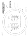
- FIG. 8A is a block functional diagram 801 of a distributed-gain-filtering optical fiber 901 (see FIG. 9A ) having medium-length filter segments.
- FIG. 8B is a block functional diagram 802 of a distributed-gain-filtering optical fiber 902 (see FIG. 9B ) having short-length filter segments.
- FIG. 8C is a block functional diagram 803 of a distributed-gain-filtering optical fiber 903 (see FIG. 9C ) having very-short-length filter segments.
- FIG. 8D is a block functional diagram 804 of a distributed-gain-filtering optical fiber 904 (see FIG. 9D ) having long-length filter segments.
- FIG. 9A is a plan-view diagram of a distributed-gain-filtering optical fiber 901 having medium-length filter segments.
- FIG. 9B is a plan-view diagram of a distributed-gain-filtering optical fiber 902 having short-length filter segments.
- FIG. 9C is a plan-view diagram of a distributed-gain-filtering optical fiber 903 having very-short-length filter segments.
- FIG. 9D is a plan-view diagram of a distributed-gain-filtering optical fiber 904 having long-length filter segments.
- FIG. 10A is a lateral-cross-section graph 1001 of an as-designed dual-core index-of-refraction profile for a dual-core waveguide fiber 1000 (shown in FIG. 10D ) useful for filtering and/or mitigation of bending loss, wherein this profile corresponds to a cross-section of a straight portion of the fiber 1000 .
- FIG. 10B is a lateral-cross-section graph 1002 of an index-of-refraction profile for a dual-core waveguide fiber 1000 (shown in FIG. 10D ), wherein this profile corresponds to a cross-section of a portion of fiber 1000 bent to a bend radius of 30 cm.
- FIG. 10C is a lateral-cross-section graph 1003 of an index-of-refraction profile for a dual-core waveguide fiber 1000 (shown in FIG. 10D ), wherein this profile corresponds to a portion of fiber 1000 bent to a bend radius of 15 cm.
- FIG. 10D is a plan-view diagram of a dual-core waveguide fiber 1000 useful for filtering and/or mitigation of bending loss, wherein profile 1001 corresponds to a straight portion of the fiber 1000 , profile 1002 corresponds to a portion of fiber 1000 bent to a bend radius of 30 cm, and profile 1003 corresponds to a portion of fiber 1000 bent to a bend radius of 15 cm.
- sections in which the bend radius is the opposite direction denoted as minus 15 cm when doped region 1018 becomes the outermost core (relative to the center of the bend radius of the coiled fiber 1000 ), and minus 30 cm when the intermediate core 1019 becomes the guiding core (in some embodiments, a core having absorbing region at the periphery of the core and an undoped center portion of the core as described in U.S. Pat. No. 7,400,807 on Jul. 15, 2008, which is incorporated herein by reference in its entirety.
- FIG. 10E is a 3-D side-view perspective-view graph 1005 of the indices-of-refraction profiles and schematic mode profiles for dual-core waveguide fiber 1000 useful for launching, amplifying, filtering and/or mitigation of bending loss in the signal light, wherein profile 1001 corresponds to a straight portion of the fiber 1000 , and profile 1003 corresponds to a portion of fiber 1000 bent to a bend radius of 15 cm.
- FIG. 10F is a 3-D end-side-perspective-view graph 1006 of the indices-of-refraction profiles and schematic mode profiles for dual-core waveguide fiber 1000 useful for filtering and/or mitigation of bending loss, wherein profile 1001 corresponds to a straight portion of the fiber 1000 , and profile 1003 corresponds to a portion of fiber 1000 bent to a bend radius of 15 cm.
- FIG. 10G is a 3-D end-view graph 1007 of the indices-of-refraction profiles and schematic mode profiles for dual-core waveguide fiber 1000 useful for filtering and/or mitigation of bending loss, wherein profile 1001 corresponds to a straight portion of the fiber 1000 , and profile 1003 corresponds to a portion of fiber 1000 bent to a bend radius of 15 cm.
- FIG. 10H is a 3-D end-view graph 1008 of the indices-of-refraction profiles and schematic mode profiles for dual-core waveguide fiber 1000 useful for filtering and/or mitigation of bending loss, wherein profile 1001 corresponds to a straight portion of the fiber 1000 , and profile 1003 corresponds to a portion of fiber 1000 bent to a bend radius of 15 cm.
- FIG. 11 is a plan-view diagram of a plurality-of-cores waveguide fiber 1100 useful for filtering and/or mitigation of bending loss, wherein this deployment concept introduces ASE filtering to the dual core or asymmetric graded fibers described above.
- FIG. 12A is a transverse cross-section-view index-of-refraction diagram 1201 of a straight section of an asymmetric-core fiber 1200 useful for filtering and/or mitigation of bending loss, wherein deployment in a straight and curved configuration introduces amplification and/or ASE filtering to signal light propagating in the core.
- FIG. 12B is a longitudinal cross-section-view index-of-refraction diagram 1202 of the straight section of the asymmetric-core fiber 1200 of FIG. 12A .
- FIG. 12C is a transverse cross-section-view index-of-refraction diagram 1203 of a curved section of the asymmetric-core fiber 1200 of FIG. 12A .
- FIG. 12D is a longitudinal cross-section-view index-of-refraction diagram 1204 of the curved section of the asymmetric-core fiber 1200 of FIG. 12A .
- the present situation is well-described by:
- Introducing a grade to a multimode fiber typically shrinks the initial mode field, but the grading mitigates the distortion when the fiber is bent.
- Dong et al. from IMRA (Dong et al., “Bend-resistant fundamental mode operation in ytterbium-doped leakage channel fibers with effective areas up to 3160 ⁇ m 2 ,” OPTICS EXPRESS, Vol. 14, No. 24, pp. 11512-11519) have designed bend-loss-mitigating micro-structured fibers, but these leakage-channel waveguides share the property of step-index LMA fibers in that the mode-field shrinks in the bend.
- the current invention uses micro-structuring fabrication techniques to design a bend-compensated profile which would be applicable to either multimode or single-mode LMA designs.
- the technique may also be beneficial in the packaging of rod-fibers. Opposition to deployment of these structures often highlights the packaging issue for a rigid glass rod when it becomes longer than a practical limit (imposed, e.g., by packaging and form-factor considerations) of, say, 50 cm.
- a rod or fiber with effective area currently only supported by a rod
- packaging is facilitated and the rod can also be lengthened, thus increasing the useable range of operation (e.g., high average powers with less heat/length).
- the present invention uses micro-structuring (or nano-structuring within one or more of the cells) stack-and-draw fabrication techniques to realize a refractive-index profile with an asymmetric profile which can compensate for bend-induced distortion and/or loss.
- micro-structuring or nano-structuring within one or more of the cells stack-and-draw fabrication techniques to realize a refractive-index profile with an asymmetric profile which can compensate for bend-induced distortion and/or loss.
- 6,711,918 by instead bundling together a plurality of glass rods of various specific physical, chemical, or optical properties that, when fused together and drawn into a fiber, provide bend-compensating sloping of the refractive index from one side of the cladding to another side of the cladding, and/or having a different refractive-index or active-species-doping profiles on one side of the core than another side of the core.
- the present invention uses a graded refractive-index profile (which may be multimode) in which the rare-earth dopant is placed asymmetrically with the fiber oriented so that the dopant is on the outside of the bend. In this case advantage can be gained even if the original refractive-index profile is symmetric.
- the present invention modifies the preform structure described in U.S. Pat. No. 6,711,918, by instead bundling together a plurality of glass rods of various specific physical, chemical, or optical properties that, when fused together and drawn into a fiber, provide the desired dopant profile (e.g., with the active dopant only on, or more concentrated on, the side of the core that faces the outside of the bend).
- the various fiber structures and cladding-and-core-index profiles and core-doping profiles described in these patents and patent applications are modified as described herein in order to provide compensation for bend-induced index sloping, and in order to have a plurality of cores, each having a different index and/or doping profile, wherein the designer can transfer the signal-wavelength light mode from one core to another core by simply bending the fiber to one or another of its design bend radii.
- Each one of a plurality of different cores in the same fiber can have different effects on the signal mode, such as guiding, filtering, mode shaping, and/or amplifying.
- the fiber can be wound on adjacent cooling cylinders of different radii, wherein as the fiber transitions from one bend radius on one cooling cylinder to another bend radius on another cooling cylinder, the signal mode is moved from one core to another core. Further, the transition radius where the signal is between core regions can be used to form a resonant structure that is tuned to propagate only a very narrow band of signal wavelengths and to radiate or reject other wavelengths, thus filtering the wavelength of the signal mode.
- the present invention combines a certain amount of index asymmetry and dopant asymmetry that are utilized together to engineer an optimized solution for a coiled or curved optical-amplifier waveguide.
- FIG. 1B shows a graph 102 of the perturbation of index-of-refraction profiles at various bend radii (index profile 125 for straight fiber, index profile 124 for 25-cm radius curved fiber, index profile 123 for 20-cm radius curved fiber, index profile 122 for 15-cm radius curved fiber, and index profile 121 for 10-cm radius curved fiber) for a single-mode fiber at a reduced NA of 0.02, which can easily be achieved by micro-structuring.
- micro-structured fibers such as, e.g., U.S. Pat. No. 6,711,918 to Kliner et al., which is incorporated herein by reference
- FIG. 1C shows a profile whose shape is a mirror, i.e., a side-to-side sloped grading of the index-of-refraction function that is in the opposite side-to-side direction of the bend-induced index-of-refraction profile, and which is used, in some embodiments, for providing bend compensation.
- a linear ramp to the index profile 132 across the diameter of the fiber in the plane of the bend results in an effective step index when the fiber is then bent to the correct designed-for radius.
- the fiber has a certain amount of tolerance built in. In fact, bending beyond the design radius of this fiber would have less impact than bending beyond the much-stricter design radius of an initial step-index fiber of comparable bend radius.
- the largest practical fiber (as opposed to a rod) is represented by a 41/200 photonic-crystal fiber (PCF) from Crystal Fibre A/S—Blokken 84, 3460 Birkerod, Denmark.
- the polarization-maintaining (PM) version of this fiber has a design bend radius of 25 cm.
- the 41/200 fiber has five rows of micro-structure cells (e.g., rows of 3, 4, 5, 4, and 3 cells each, respectively across the core) across the center of the core.
- a fiber is designed with each row of cells decreasing in index by 0.00014 relative to the previous row of cells (thus sloping the refractive index lower, as the rows progress from the side of the core facing the inside of the bend to the side of the core facing the outside of the bend); this corresponds to an index change across the core of 0.00056.
- this fiber would approximate the design for mitigating a bend radius of 11 cm.
- more rows of smaller cells can be used, wherein each row has a refractive index that differs from that of adjacent rows by a smaller amount, thus providing a finer granularity to the index slope.
- the fiber is bent (or curved) to a bend radius of 8 cm to achieve the same perturbed profile as the uniform profile bent to a bend radius of 25 cm. This is illustrated in FIG. 1D .
- the 11-cm-bend-radius-mitigation fiber for example
- the 11-cm-bend-radius-mitigation fiber has an allowable bend radius in a range from 8 cm to 14 cm. In some embodiments, this is a good tradeoff.
- FIG. 1D is a graph that shows effective index-of-refraction profiles of an 11-cm-design-radius fiber overbent to an 8-cm radius.
- the “penalty” for overbending this fiber is equivalent to bending an original step fiber to a bend radius of 25 cm. This is the design bend radius for the Crystal Fibre A/S 41/200 PM fiber. This indicates a significant amount of built-in tolerance to the compensated fiber design. It suggests that the pre-compensation not only enables the practical use of extremely large mode areas, but also introduces improved tolerances to coil optimization.
- the profile shown in FIG. 1E is constructed.
- the idealized linear ramps would actually be a staircase ramp, with the practical issues like reasonable cell size and index control tolerances determining the departure from ideal.
- asymmetry is by the shape of the core. With micro-structuring it should be possible to engineer asymmetric shapes such as trapezoidal or egg-shapes. By reducing the core dimension on the outside of the bend relative to the inside, the effective index can be fine tuned. Geometric tapering may be a means of smoothing out the saw-tooth nature of the effective profiles resulting when the stepped profiles are bent.
- FIG. 1E shows a graph of an index-of-refraction profile for mitigation of bending in an extreme waveguide design with a core diameter of 70 microns (70 ⁇ m).
- the practical issue of cell dimensions and tolerance in index step-size is taken into account.
- the index excursion within a cell is small enough for the mode to “see” the in-the-average index only.
- the above techniques are also applicable to nominally multimode waveguides under single-mode excitation.
- the index ramp required for bend mitigation depends only weakly on absolute core index, so the above scenarios are also representative of these cases.
- the present invention has the following aspects that are combined is various combinations in some embodiments of the invention:
- an indicia of the cross-sectional direction of the direction of grading of the index or the offset of index or doping profile is provided, such as a flat (a flat section on the cylindrical outer portion along the length of the fiber on its outer diameter or inner diameter shows the orientation that is to be maintained when winding the fiber around a mandrel).
- stress rods, color stripes, grooves, protrusions or other indicia are provided on the fiber to denote its intended orientation that is to be maintained when winding the fiber around the mandrel, in order that the micro-structured graded index of refraction is correctly oriented relative to the bend direction.
- FIG. 2A-1 shows a schematic cross-section of a photonic-crystal fiber (PCF) 201 having a core 217 defined by the longitudinal holes 218 or regions of lower index of refraction (rather than by various glasses or doping profiles having different indices of refraction).
- PCF 201 has a core 217 whose refractive index is micro-structured by including a plurality of rows (three vertically-oriented rows are shown here, but in other embodiments, a larger or smaller number of rows are used).
- the left-hand vertical row of cells (indicated by the two hexagonal cells marked n 0 + ) have a slightly higher index of refraction than the default refractive index n 0 that is implemented in the center vertical row of cells (indicated by the three hexagonal cells marked n 0 ), and the right-hand vertical row of cells (indicated by the two hexagonal cells marked n 0 ⁇ ) have a slightly lower index of refraction than the default refractive index n 0 .
- the core is implemented using seven cells in three rows, and there are three index values: n 0 + , n 0 , and n 0 ⁇ . This provides two index steps (n 0 + to n 0 and n 0 to n 0 ⁇ ).
- the microstructure cells of the core are doped, and in some such embodiments, the doping varies left-to-right and/or top-to-bottom across the core.
- the microstructure includes cells of the core, of the inner cladding 212 , and/or of the outer cladding 213 of the fiber.
- fiber 201 is implemented as a solid micro-structured fiber that is not using photonic-crystal techniques, but instead uses only the micro-structured cells to achieve the desired index and doping profiles.
- Fiber 201 also illustrates a photonic-crystal implementation of index slope that is achieved by using smaller longitudinal photonic-crystal holes (or areas of lower refractive index) and/or a greater spacing between holes on the side of the fiber toward the inside of the bend and by using larger longitudinal holes (or areas of lower refractive index) and/or a smaller spacing between holes on the opposite side of the fiber (the side toward the outside of the bend).
- PCF 201 includes a flat 211 in a side of the fiber outer diameter.
- the fiber structure in some embodiments, is described in terms of cells with dimensions of a few microns (e.g., perhaps 10-micron-diameter cells). These seven cells have been described as having a particular average refractive index for that cell, and the bend mitigation is achieved by stepping down the index of each cell or row of cells from the inside of a bend to the outside.
- each of these cells ( 219 , 219 ′, 219 ′′) is further structured with sub-micron (which helps ensure that the typical signal and pump wavelengths of about one micron or more encounter all sub-micron portions) spatial scaling diameters with some sub-regions having higher refractive index and others having a lower refractive index.
- FIG. 2A-4 is a graph 202 of an actual nano-cell index profile 221 for a core cell 219 to obtain a given effective cell index of n 0 ⁇ .
- FIG. 2B shows a schematic cross-section of a double-clad fiber preform 202 having a graded-index core 230 with gradually decreased index of refraction at the outside portions of the bend fabricated by micro-structured trapezoids of different indices of refraction.
- the fiber drawn from the preform 202 has the same proportions and geometry.
- five rows of cells with one cell per row are provided, with the cell 235 furthest toward the inside of the bend of the coiled fiber having the highest refractive index n 0 ++ , the next cell 234 having the next-highest refractive index n 0 + , the middle cell 233 having the default core refractive index n 0 , the next cell 232 having the next-lower refractive index n 0 ⁇ and the next cell 231 having the lowest core refractive index n 0 ⁇ .
- the inner cladding 212 surrounding this core is also micro-structured to have a compositional or structural refractive-index slope that decreases from left to right (i.e., from the inside of the fiber bend to the outside of the fiber bend).
- the inner cladding 212 surrounding this core has a compositional or structural refractive-index slope that decreases from left to right and is defined by photonic-crystal structures that define the index slope from one side to the other of the fiber cross section.
- the pump light is launched into the inner cladding 212 and enters the core 230 along its length and the signal is launched into the core and is amplified by rare-earth doping species excited by the pump light.
- FIG. 2C is a schematic cross-section view of a double-clad fiber preform 203 having two graded-index cores 238 and 239 each made from a preform that used trapezoid-shaped core sections to generate a gradually decreasing index of refraction across the left-hand core from the center to the left, and a gradually decreasing index of refraction across the right-hand core from the center to the right.
- the fiber drawn from the preform 203 has the same proportions and geometry.
- the first core 238 includes a plurality of trapezoids with the cell 240 furthest toward the inside of the bend of the coiled fiber having the lowest refractive index n 0 ⁇ , the next cell 241 having the next-lowest refractive index n 0 ⁇ , the middle cell 242 having the default core refractive index n 0 , the next cell 243 having the next-higher refractive index n 0 + , and the next cell 244 having the highest core refractive index n 0 ++ .
- the inner cladding 212 surrounding this core is also micro-structured to have a compositional or structural refractive-index slope that increases from left side to a vertical line in the middle (i.e., from the inside of the fiber bend to the center of the fiber bend) and that decreases from the vertical line in the middle to right side (i.e., from the center of the fiber bend to the outside of the fiber bend).
- the inner cladding 212 surrounding this core has a compositional or structural refractive-index slope that increases from the left side to a vertical line in the middle and decreases from the vertical line in the middle to the right side and is defined by photonic-crystal structures that define the index slope from one side to the other of the fiber cross section.
- the second core 239 includes a plurality of trapezoids with the cell 245 furthest toward the inside of the bend of the coiled fiber having the highest refractive index n 0 ++ , the next cell 246 having the next-highest refractive index n 0 + , the middle cell 247 having the default core refractive index n 0 , the next cell 248 having the next-lower refractive index n 0 ⁇ , and the next cell 249 having the lowest core refractive index n 0 ⁇ .
- the inner cladding 212 surrounding this core is also micro-structured to have a compositional or structural refractive-index slope that decreases from left to right (i.e., from the inside of the fiber bend to the outside of the fiber bend).
- the inner cladding 212 surrounding this core has a compositional or structural refractive-index slope that has a gradually decreasing index of refraction across the left-hand side of cladding 212 from the center to the left, and a gradually decreasing index of refraction across the right-hand side of cladding 212 from the center to the right and this index-of-refraction profile is defined by photonic-crystal structures that define the index slope from one side to the other of the fiber cross section.
- the first core 238 is not doped or is substantially undoped, while the second core 239 is doped by one or more rare-earth doping species that absorb pump light having a pump-light wavelength and amplify signal light having a signal-light wavelength.
- the pump light is launched into the inner cladding 212 and enters the cores 238 and 239 along their length and the signal is launched into the first core 238 or into both cores 238 and 239 (e.g., in some embodiments, at the end of a straight section of the fiber or in other embodiments, at the end of a section that curves to the right such that the left-hand side of the FIG.
- the cross-sectional index profile shown in FIG. 6A corresponds to the cross-sectional index profile of a dual-core fiber drawn from preform 203 when that fiber is bent to the right (such that the inside of the bend is the right-hand side of FIG. 2C ), the cross-sectional index profile shown in FIG.
- FIG. 6B corresponds to the cross-sectional index profile of a dual-core fiber drawn from preform 203 when that fiber is straight
- the cross-sectional index profile shown in FIG. 6C corresponds to the cross-sectional index profile of a dual-core fiber drawn from preform 203 when that fiber is bent to the left (such that the inside of the bend is the left-hand side of FIG. 2C ).
- the spacing between core 238 and core 239 is designed such that when the fiber is straight or bent to the right, light of the desired signal wavelength transfers from one core to the other while other wavelengths do not transfer as well, thus providing a filter segment such as described in FIGS. 8A-8D and 9 A- 9 D, while when the fiber is bent in the proper direction to its design radius, the signal is amplified by rare-earth doping species excited by the pump light in the second core 239 thus forming an amplifying segment.
- the filter segments and the amplifier segments are alternated such that the signal is alternately and repeatedly amplified and filtered.
- FIG. 2D is a schematic cross-section view of a double-clad fiber preform 204 having single graded-index core 261 made from a preform that used trapezoid-shaped core sections to generate a gradually decreasing index of refraction across the left-hand-side of the core 261 from the center to the left, and across the right-hand-side of the core from the center to the right.
- the fiber drawn from the preform 204 has the same proportions and geometry.
- five rows of cells with one cell per row are provided for each half of single core 261 , wherein the left-half of core 261 includes a plurality of trapezoids with the cell 250 furthest toward the inside of the bend of the coiled fiber having the lowest refractive index n 0 ⁇ , the next cell 251 having the next-lowest refractive index n 0 ⁇ , the middle cell 252 having the default core refractive index n 0 , the next cell 253 having the next-higher refractive index n 0 + , and the next cell 254 having the highest core refractive index n 0 ++ .
- the right-hand-side of the core 261 includes a plurality of trapezoids with the cell 255 furthest toward the inside of the bend of the coiled fiber having the highest refractive index n 0 ++ , the next cell 256 having the next-highest refractive index n 0 + , the middle cell 257 having the default core refractive index n 0 , the next cell 258 having the next-lower refractive index n 0 ⁇ , and the next cell 259 having the lowest core refractive index n 0 ⁇ .
- the inner cladding 212 surrounding this core is also micro-structured to have a compositional or structural refractive-index slope that gradually increases from the left-hand side of cladding 212 to a vertical line in the middle (i.e., from the inside of the fiber bend to the center of the fiber bend) and that gradually decreases from the vertical line in the middle to the right-hand side of cladding 212 (i.e., from the center of the fiber bend to the outside of the fiber bend).
- index profile of the inner cladding 212 is defined by photonic-crystal structures that define the index slope from one side to the other of the fiber cross section.
- the left-hand half of core 261 is not doped or is substantially undoped, while the right-hand half of core 261 is doped by one or more rare-earth doping species that absorb pump light having a pump-light wavelength and amplify signal light having a signal-light wavelength.
- the pump light is launched into the inner cladding 212 and enters the core 261 along its length and the signal is launched into the left-hand half of core 261 or into both halves of core 261 (e.g., in some embodiments, at the end of a straight section of the fiber or in other embodiments, at the end of a section that curves to the right such that the left-hand side of the FIG.
- the cross-sectional index profile 701 shown in FIG. 7A corresponds to the cross-sectional index profile of a dual-core fiber drawn from preform 204 when that fiber is bent to the right (such that the inside of the bend is the right-hand side of FIG. 2D ), the cross-sectional index profile 702 shown in FIG.
- FIG. 7B corresponds to the cross-sectional index profile of a dual-core fiber drawn from preform 204 when that fiber is straight
- the cross-sectional index profile shown in FIG. 7 C corresponds to the cross-sectional index profile of a dual-core fiber drawn from preform 204 when that fiber is bent to the left (such that the inside of the bend is the left-hand side of FIG. 2D ).
- FIG. 3A shows a schematic graph 301 of the index of refraction 320 and mode profile 330 across a cross-section of a conventional prior-art fiber having a graded-index core with symmetrical index changes in all directions from the axis of the core when the conventional fiber is in a straight (unbent and uncoiled) state.
- the core index and doped region 340 of the conventional prior-art fiber start centered to one another.
- FIG. 3B shows a schematic graph 302 of the index of refraction 321 and mode profile 331 across a cross-section of the conventional prior-art fiber when the conventional fiber is in a bent and/or coiled state.
- FIG. 4A shows a schematic graph 401 of the index of refraction 420 and mode profile 430 across a cross-section of a fiber according to some embodiments of the invention having a graded-index core with its doped region 440 to the outside of the core with symmetrical index changes in all directions from the axis of the core when the conventional fiber is in a straight (unbent and uncoiled) state.
- FIG. 4B shows a schematic graph 402 of the index of refraction 421 and mode profile 431 across a cross-section of the fiber of the invention when the fiber is in a bent and/or coiled state, which forces the mode of the laser light to the outside of the core, thus overlapping the doped region 440 .
- FIG. 5A shows a schematic perspective view of a fiber 501 of the present invention that includes a curved-fiber portion 510 coiled around a mandrel 513 and spliced to transitional or conventional pigtails 511 and 512 at each end 514 and 513 , respectively, in order to transition from an index profile suited for straight runs of fiber to an index profile that is compensated for being bent or coiled.
- FIG. 5B shows a schematic perspective view of a fiber 502 of the present invention that includes a curved-fiber portion 510 being drawn and coiled around a mandrel 513 before hardening.
- a fiber 502 of the present invention that includes a curved-fiber portion 510 being drawn and coiled around a mandrel 513 before hardening.
- mandrel 513 before fiber/rod 510 hardens, air pressure or vacuum to different holes varies their sizes as glass cools to change straight-core profile to curved-core profile and back again.
- mandrel 513 includes a start block 521 where fiber 510 starts to wrap around mandrel 513
- mandrel 513 includes an end block 522 where mandrel forming stops.
- FIG. 5C shows a schematic perspective view of a fiber 503 of the present invention that includes a curved-fiber portion 510 coiled around a mandrel 513 and spliced to transitional slightly-curved pigtails 533 and 535 at each end, which are then spliced to straight fibers in order to transition from an index profile suited for straight runs of fiber to an index profile that is compensated for being bent or coiled.
- FIG. 5D shows a schematic perspective view of a fiber 504 of the present invention, wherein the fiber's holes have been expanded and/or contracted (e.g., by gas pressure and/or vacuum during the heating and drawing of the fiber and or afterward when the fiber is already wrapped around the mandrel) in order to provide a high NA initial section (represented by the uppermost cross-section 541 with identical large holes (which provide low effective index, and thus a larger step down from the core index) surrounding the core (the center location with no hole)).
- This is transitioned to a section having a very low NA (represented by the mid-upper cross-section 542 with identical small holes (which provide low effective index, and thus a larger step down from the core index) surrounding the core (the center location with no hole)).
- This is transitioned to a section having a sloped index wrapped or coiled around the mandrel (represented by the mid-lower cross-section 543 with graduated-sized holes (small to the inside of the coil and larger to the outside of the coil (which provide sloped as-drawn index but an even effective index when wrapped on the mandrel) surrounding the core (the center location with no hole)).
- This is then transitioned to a section having a very low NA (represented by the lower-most cross-section 544 with identical small holes (which provide low effective index, and thus a larger step down from the core index) surrounding the core (the center location with no hole)).
- FIG. 5E shows a schematic cross-sectional and graph view of a fiber 505 of the present invention coiled or bent in a semicircle with a slanted index profile having a higher index on the inside of the curve, a lower index to the outside of the curve, and offset-spliced to transitional straight or slightly-curved pigtails at each end that launch the signal light from the center mode of the pigtail core to the inside edge of the core that is then bent to its optimal curve to force the mode to the center of the coiled portion, where the dopant is located.
- pump light (large dotted arrow 562 ) is launched into the inner cladding 551 of a pigtail 558 that includes a core 550 , the inner cladding 551 , and an outer cladding 552 .
- signal light (small solid arrow 563 ) is launched into core 550 with an input-signal mode profile 555 in the center of the pigtail core 550 .
- a pigtail core index profile 556 is centered.
- the pigtail 558 connects to a fiber section 568 via an offset splice 554 , wherein the fiber section 568 includes a core 569 having a rare-earth doped region 553 in the center of the core 569 .
- core 569 has a slanted index profile 558 .
- the input-signal mode profile 555 of the pigtail 558 becomes the initial-signal mode profile 557 that goes into the edge of core 569 and shifts toward the edge of rare-earth doped region 553 in the straight section of the fiber to become shifted signal-mode profile 559 .
- signal-mode profile 560 is centered in rare-earth doped region 553 by effective index profile 561 in the curve of the fiber.
- signal light (large solid arrow 565 ) exits the fiber from the center of core 569 and residual pump light (small dotted arrow 564 ) exits the fiber from the inner cladding of the fiber section 568 .
- FIG. 5F is a schematic cross-sectional and graph view of a fiber 506 of the present invention coiled or bent in a semicircle with a conventional symmetric index profile but with doping on the outside of the curve, wherein the curved fiber section is spliced to conventional undoped pigtails at each end, wherein the pigtails are used to launch the signal light from the center mode of the pigtail core to the center of the core that is then bent to a curve that forces the mode to the outside edge of the core, where the dopant is located, and after amplification the far end of the fiber is again spliced to a pigtail for delivering the amplified signal.
- signal light (small solid arrow 571 ) is launched into core 572 of a pigtail 587 , wherein signal light 571 has an input mode profile 575 .
- the pigtail 587 includes an inner cladding 573 , an outer cladding 574 , and a pigtail-core index profile 576 .
- signal light 571 enters a fiber section 588 from the pigtail 587 and there has an initial mode profile 577 in the straight portion of the fiber section 588 .
- the straight portion of fiber section 588 has a core index profile 578 .
- fiber section 588 includes a rare-earth-doped region 570 to a side of core 589 , wherein that side of the core 589 is near the outside edge of the curve of the curved portion of fiber section 588 .
- the mode profile 579 of the signal light shifts to the outer edge of fiber core 589 in the curved portion of fiber section 588 so that it is centered in the rare-earth-doped region 570 .
- FIG. 6A is a graph 601 (which shows a 2D cross-section of the index of refraction) of an as-designed dual-core index-of-refraction profile of the inner cladding and cores for a dual-core waveguide fiber 600 (shown in FIG. 6D ) useful for filtering and/or mitigation of bending loss, wherein this profile corresponds to a straight portion of the fiber 600 .
- one core e.g., the left-hand core
- another core e.g., the right-hand core
- doping of a laser species e.g., one or more rare-earth elements
- pump light i.e., light having a wavelength suitable for pump absorption
- amplify signal light i.e., light having a wavelength suitable for amplification by the lasing species
- the undoped core would guide the signal light and the cladding surrounding the undoped core would guide the pump light and substantially prevent absorption of pump light by the doped core when the fiber is held straight (e.g., when the fiber is not wrapped around a cooling drum, thus preventing overheating of the fiber in locations that are not providing cooling. Then, when the fiber is bent to a design radius (wrapped around a cooling cylinder) that increases the effective index of refraction on the outside of the bend radius (such as shown in FIG.
- the signal light and any pump light in the undoped core are automatically transferred to the doped core, and the pump light in the cladding surrounding the undoped core is automatically transferred to the cladding surrounding the doped core, and amplification occurs to absorption of pump light and stimulated amplification of the signal light.
- the fiber is again held in a straight configuration and light automatically transfers back to the undoped core.
- an intermediate bend radius allows filtering of the signal light by allowing escape of amplified spontaneous emission (ASE) light that is not in the primary mode of the signal light.
- a plurality of design-radius amplifying sections are alternated with one or more filtering sections having an intermediate bend radius (i.e., a radius between straight and the design radius).
- the “design radius” is the radius at which the signal mode is in a desired core generally located to the outside the other core(s) relative to a center of a bend radius equaling the design radius.
- having three or more cores e.g., in some embodiments, cores that are in a plane of a circle of the bend radius, such that an inner core (the core that would be innermost when the fiber is bent to some radius) has a highest index of refraction (and thus guides the signal mode) when the fiber is straight
- one or more middle cores successively have the highest index when the fiber is bent to a corresponding intermediate radius (two or more middle cores could use two or more corresponding bend radii)
- an outer core has a highest index of refraction (and thus guides the signal mode) when the fiber is bent to its smallest bend radius.
- the index of refraction is slanted (graded) on one side of the fiber (e.g., the right half in FIG. 6A ), but relatively normal (i.e., a core having a higher index 612 than the index 611 of the surrounding cladding) on the opposite side (e.g., the left half in FIG. 6A ).
- one half of the fiber would have one or more undoped cores having higher index 612 , wherein the mode of the signal would be substantially centered in the left-hand core.
- one or more second right-hand cores having a graded index 614 would be located within a right-hand cladding having a correspondingly graded index 613 .
- an outer cladding (with a lower index, not shown here, for example an index of 1.44, which is lower than any of the indices shown here, would guide all pump light to remain within the cladding 611 and 613 in this example).
- any signal and/or pump light launched into the left-hand core having index 612 would be guided within the left-hand core, while pump light launched into the cladding having index 611 would stay in an inner cladding that is inside the outer cladding (not shown here), and the pump light would transfer into one of the cores (the core within the inner-cladding portion having the highest cladding index) along a length of the fiber.
- Any pump light that had launched or been transferred into the undoped core would stay in that core until the fiber started to bend, where upon it would automatically transfer to the doped core and be used to excite the lasing species to amplify the signal light.
- any pump light that was launched into the right-hand cladding (the cladding whose index increases from right-to-left) and/or core (whose index also increases from right-to-left) would be transferred leftward into the left-hand cladding and/or core when the fiber is held straight.
- the pump and signal light would stay in the left-hand cladding and/or core as long as the fiber is held straight, and pump and signal light would automatically shift to the left-hand cladding and/or core when the fiber is bent to its design radius.
- FIG. 6D , FIG. 6E , FIG. 6F , and FIG. 6G show perspective views of the index of refraction of fiber 600 when in the straight configuration of FIG.
- the mode 615 is in the left-hand core of fiber 600 .
- some embodiments guide substantially all of the signal mode in the left-hand core and substantially none of the signal mode in the right-hand core.
- FIG. 6B is a graph 602 of an index-of-refraction profile (which shows a 2D length-wise cross section of the index of refraction values; where the middle one-third of FIG. 6D , FIG. 6E , FIG. 6F , and FIG. 6G , show 3D perspective views of the index of refraction of fiber 600 when in the 40-cm-bend-radius configuration of FIG. 6B ) for a dual-core waveguide fiber 600 (shown in FIG. 6D ), wherein this profile corresponds to a portion of fiber 600 bent to a bend radius of 40 cm.
- the previously flat core index 612 shown in FIG. 6A slants to the graded core index 622 of FIG. 6B
- the previously graded cladding index 613 becomes the less-slanted graded cladding index 623
- the previously graded core index 614 becomes the less-slanted graded core index 624 .
- the signal mode shifts to the region having the highest index of refraction, this being the right-hand portion of the left-hand core and the left-hand portion of the right-hand core, and perhaps some in the cladding region between the two cores, as shown by mode 625 in the middle one-third graphs of FIG. 6D , FIG. 6E , FIG. 6F , and FIG. 6G .
- some embodiments guide substantially half of the signal mode in the left-hand core and substantially half of the signal mode in the right-hand core.
- FIG. 6C is a graph 603 of an index-of-refraction profile (which shows a 2D length-wise cross section of the index of refraction values; where the right-hand one-third of FIG. 6D , FIG. 6E , FIG. 6F , and FIG. 6G , show 3D perspective views of the index of refraction of fiber 600 when in the 20-cm-bend-radius configuration of FIG. 6B ) for a dual-core waveguide fiber 600 (shown in FIG. 6D ), wherein this profile corresponds to a portion of fiber 600 bent to a bend radius of 20 cm.
- the signal mode shifts rightward to the region having the highest index of refraction, this being the right-hand core, and substantially none in the left-hand core or in the cladding regions around the two cores, as shown by mode 635 in the right-hand one-third graphs of FIG. 6D , FIG. 6E , FIG. 6F , and FIG. 6G .
- some embodiments guide substantially none of the signal mode in the undoped left-hand core and substantially all of the signal mode in the doped right-hand core.
- two or three (or more) cooling cylinders are provided such that the fiber can alternate between a 20-cm bend-radius configuration around a 20-cm-radius heat-sink cylinder wherein the signal is being amplified and a 40-cm bend-radius configuration around a 40-cm-radius heat-sink cylinder wherein the signal is being filtered to remove ASE that may have been introduced in a prior amplifying section, and shown and described in the fiber-amplifier-filter block diagrams of FIG. 8A , FIG. 8B , FIG. 8C , and FIG. 8D , and in the plan views of the fiber in FIG. 9A , FIG. 9B , FIG. 9C , and FIG. 9D .
- FIG. 6D is a 3-D side perspective-view graph 604 of the indices-of-refraction profiles and schematic mode profiles for a dual-core waveguide fiber 600 useful for filtering and/or mitigation of bending loss, wherein left-hand profile 601 corresponds to a straight portion of the fiber 600 (a cross-section of which is shown in two dimensions in FIG. 6A ), middle profile 602 corresponds to a portion of fiber 600 bent to a bend radius of 40 cm (a cross-section of which is shown in two dimensions in FIG. 6B ), and right-hand profile 603 corresponds to a portion of fiber 600 bent to a bend radius of 20 cm (a cross-section of which is shown in two dimensions in FIG. 6C ).
- left-hand profile 601 corresponds to a straight portion of the fiber 600 (a cross-section of which is shown in two dimensions in FIG. 6A )
- middle profile 602 corresponds to a portion of fiber 600 bent to a bend radius of 40 cm (a cross-section of which is shown in two dimensions in FIG.
- depictions are of cross sections perpendicular to the direction of propagation. Note however that these figures are depictions of graphs of the index of refraction of a fiber 600 , wherein higher index is upward in the graph, front-to-back is one dimension of the variation in index of refraction in a front-to-back direction across cross-section of fiber 600 , and left-to-right is a perpendicular dimension of the variation in index of refraction in a left-to-right direction across a cross-section of fiber 600 .
- mode profile 615 for the straight section of fiber is also shown.
- mode profile 625 for the 40-cm-bend-radius section of fiber is also shown.
- mode profile 635 for the 40-cm-bend-radius section of fiber is also shown.
- FIG. 6E is a 3-D side-view graph 605 of the indices-of-refraction profiles and schematic mode profiles for dual-core waveguide fiber 600 . These three graphs are just another perspective of the corresponding three graphs of FIG. 6D (i.e., they are the same graphs viewed from another direction).
- FIG. 6F is a 3-D end-side-perspective-view graph 606 of the indices-of-refraction profiles and schematic mode profiles for dual-core waveguide fiber 600 . These three graphs are just yet another perspective of the corresponding three graphs of FIG. 6D .
- FIG. 6G is a 3-D end-view graph 607 of the indices-of-refraction profiles and schematic mode profiles for dual-core waveguide fiber 600 . These three graphs are just yet another perspective of the corresponding three graphs of FIG. 6D .
- fiber 700 is similar to fiber 600 described in FIG. 6A-FIG . 6 G, except that the two cores overlap one another in the center.
- the single-core index-of-refraction profile of graph 701 includes a first-side cladding having a higher flat index profile 711 , an undoped core part having a flat index profile 712 that touches a doped core part having a slanted-down index profile 714 , and a second-side cladding having a slanted-down index profile 713 .
- FIG. 7B is a graph 702 of an index-of-refraction profile for two-part single-core waveguide fiber 700 (a 3-D side perspective-view diagram of the index profile 702 of FIG. 7B is shown as graph 702 in FIG. 7D ), wherein this profile corresponds to a portion of fiber 700 bent to a bend radius of 40 cm. As shown in graphs 702 of FIG. 7B and FIG.
- the single-core index-of-refraction profile of graph 702 includes a first-side cladding having a moderately slanted-up index profile 721 , an undoped core part having a higher moderately slanted-up index profile 722 that touches a doped core part having a moderately slanted-down index profile 724 , and a second-side cladding having a lower moderately slanted-down index profile 723 .
- FIG. 7C is a graph 703 of an index-of-refraction profile for two-part single-core waveguide fiber 700 (a 3-D side perspective-view diagram of the index profile 703 of FIG. 7C is shown as graph 703 in FIG. 7D ), wherein this profile corresponds to a portion of fiber 700 bent to a bend radius of 20 cm. As shown in graphs 703 of FIG. 7C and FIG.
- the single-core index-of-refraction profile of graph 703 includes a first-side cladding having a slanted-up index profile 731 , an undoped core part having a higher slanted-up index profile 732 that touches a doped core part having a flat index profile 734 , and a second-side cladding having a lower flat index profile 733 .
- FIG. 7D is a 3-D side perspective-view graph 704 of the indices-of-refraction profiles and schematic mode profiles for a dual-core waveguide fiber 700 useful for filtering and/or mitigation of bending loss, wherein profile 701 corresponds to a straight portion of the fiber 700 , profile 702 corresponds to a portion of fiber 700 bent to a bend radius of 40 cm, and profile 703 corresponds to a portion of fiber 700 bent to a bend radius of 20 cm.
- signal mode 715 is located in the undoped core part in the straight portion of fiber 700 having flat index profile 712 of straight profile 701 .
- signal mode 725 is located partly in undoped core part having the moderately slanted-up core index profile 722 and partly in the doped core part having the moderately slanted-down index profile 724 .
- signal mode 735 is located in the doped core part having the flat index profile 734 .
- FIG. 8A is a block functional diagram 801 of a distributed-gain-filtering optical fiber 901 (see FIG. 9A ) having medium-length filter segments.
- input signal 98 enters fiber 901 at gain segment 811 , which is followed consecutively by filter segment 812 , gain segment 813 , and filter segment 814 .
- fiber 901 further includes filter segment 816 and gain segment 817 .
- signal output 99 exits fiber 901 from gain segment 817 .
- FIG. 8B is a block functional diagram 802 of a distributed-gain-filtering optical fiber 902 (see FIG. 9B ) having short-length filter segments.
- fiber 902 includes gain segment 821 , which is followed consecutively by filter segment 822 , gain segment 823 , and filter segment 824 .
- fiber 902 further includes filter segment 826 and gain segment 827 .
- signal output exits fiber 902 from gain segment 827 .
- FIG. 8C is a block functional diagram 803 of a distributed-gain-filtering optical fiber 903 (see FIG. 9C ) having very-short-length filter segments.
- fiber 903 includes gain segment 831 , which is followed consecutively by filter 832 , and gain segment 833 .
- fiber 903 further includes filter 836 and gain segment 837 .
- signal output exits fiber 903 from gain segment 837 .
- FIG. 8D is a block functional diagram 804 of a distributed-gain-filtering optical fiber 904 (see FIG. 9D ) having long-length filter segments.
- fiber 904 includes gain segment 841 , filter segment 842 , filter segment 846 , and gain segment 847 .
- signal output exits fiber 904 from gain segment 847 .
- FIG. 9A is a plan-view diagram of a distributed-gain-filtering optical fiber 901 having medium-length filter segments, which corresponds to the block diagram of FIG. 8A .
- a plurality of gain sections 911 and 913 (which are each formed by bending the fiber 901 to a 20-cm bend radius, to force the signal light to the outer core that has been doped with a rare-earth gain dopant, and which thus amplifies the signal light) are alternated with a plurality of medium-length filter sections 912 and 914 (which are each formed by bending the fiber 901 to a 40-cm bend radius, in order to allow higher-order-mode amplified-spontaneous-emission (ASE) light to disperse from the core region).
- input pigtail 918 connects to a gain section 911 and output light 99 exits output pigtail 919 that is connected to a gain section 913 .
- FIG. 9B is a plan-view diagram of a distributed-gain-filtering optical fiber 902 having short-length filter segments.
- a plurality of gain sections 921 and 923 (which are each formed by bending the fiber 902 to a 20-cm bend radius, to force the signal light to the outer core that has been doped with a rare-earth gain dopant, and which thus amplifies the signal light) are alternated with a plurality of short-length filter sections 922 and 924 (which are each formed by bending the fiber 902 to a 40-cm bend radius, in order to allow higher-order-mode amplified-spontaneous-emission (ASE) light to disperse from the core region).
- input pigtail 928 connects to a gain section 921 and output light 99 exits output pigtail 929 that is connected to a gain section 923 .
- FIG. 9C is a plan-view diagram of a distributed-gain-filtering optical fiber 903 having very-short-length filter segments.
- a plurality of gain sections 931 and 933 (which are each formed by bending the fiber 903 to a 20-cm bend radius, to force the signal light to the outer core that has been doped with a rare-earth gain dopant, and which thus amplifies the signal light) are alternated with a plurality of very-short-length filter sections 932 and 934 (which are each formed by bending the fiber 903 to a 40-cm bend radius, in order to allow higher-order-mode amplified-spontaneous-emission (ASE) light to disperse from the core region).
- input pigtail 938 connects to a gain section 931 and output light 99 exits output pigtail 939 that is connected to a gain section 933 .
- FIG. 9D is a plan-view diagram of a distributed-gain-filtering optical fiber 904 having long-length filter segments.
- a plurality of gain sections 941 (which are each formed by bending the fiber 904 to a 20-cm bend radius, to force the signal light to the outer core that has been doped with a rare-earth gain dopant, and which thus amplifies the signal light) are alternated with a plurality of relatively long-length filter sections 942 (which are each formed by bending the fiber 904 to a 40-cm bend radius, in order to allow higher-order-mode amplified-spontaneous-emission (ASE) light to disperse from the core region).
- input pigtail 948 connects to a gain section 941 and output light 99 exits output pigtail 949 that is connected to another gain section 941 .
- a sloped-profile fiber is fabricated with a plurality of cores having a plurality of purposes, such as one or more cores that are optimized for launching signal and/or pump light into the cores (e.g., similar to the undoped core 612 of FIG. 6A ), one or more cores having one or more species of rare-earth doping for absorbing pump light and/or amplifying signal light, and/or one or more cores designed for filtering the signal mode (e.g., to reduce higher-order modes or ASE light).
- cores having a plurality of purposes, such as one or more cores that are optimized for launching signal and/or pump light into the cores (e.g., similar to the undoped core 612 of FIG. 6A ), one or more cores having one or more species of rare-earth doping for absorbing pump light and/or amplifying signal light, and/or one or more cores designed for filtering the signal mode (e.g., to reduce higher-order modes or ASE light).
- FIG. 10A is a lateral-cross-section graph 1001 of an as-designed dual-core index-of-refraction profile for a dual-core waveguide fiber 1000 (shown in FIG. 10D ) useful for launching, amplifying, filtering and/or mitigation of bending loss, wherein this profile corresponds to a cross-section of a straight portion of the fiber 1000 .
- fiber 1000 includes a plurality of cores (in this embodiment example, five core regions are provided), wherein when fiber 1000 is straight, the signal light can be launched and guided in undoped center core 1012 within center cladding 1011 .
- center core 1012 On either side of center core 1012 are an undoped region 1015 surrounded by absorbing regions 1014 within sloped-index cladding 1013 , and a similar structure 1019 on the opposite side. Since the index of refraction of these side regions is sloped upward towards the middle, light in these regions will tend move to the center region, such that the signal light is guided only in the center core. Further to the outside on both sides are doped regions 1017 and 1018 , each in a respective cladding 1016 .
- pump light is launched into one or more of the cladding regions. In some embodiments, pump light is launched into one or more of the core regions. See FIGS. 10E , 10 F, 10 G, and 10 H for other depictions of this same index and doping profile 1001 for straight sections of fiber 1000 .
- each core can have a different guiding, filtering, and amplifying characteristics, different doping concentrations, and different numerical apertures (or other variations).
- the cladding surrounding each core can be configured for different pump-light guiding properties such that the pump light can be guided into an amplifying core further down the fiber if desired.
- FIG. 10B is a lateral-cross-section graph 1002 of an index-of-refraction profile for a dual-core waveguide fiber 1000 (shown in FIG. 10D ), wherein this profile corresponds to a cross-section of a portion of fiber 1000 bent to a bend radius of 30 cm.
- undoped core 1012 of FIG. 10A becomes slanted undoped region 1022 in FIG. 10B
- side regions 1014 and 1015 of FIG. 10A become the guiding core in FIG. 10B .
- a signal-absorbing region is to the outside of an undoped core 1025 and its absorbing regions 1025 (also having their index raised by the bend) which have the highest index when fiber 1000 is slightly bent (e.g., to a bend radius of 30 cm) such that the sloped index of the straight fiber is tilted by the bend to raise the relative index of the fiber to the outside of the bend and lower the relative index of the fiber to the inside of the bend.
- the index of the entire fiber is tilted relative to the index 1001 of the straight fiber shown in FIG. 10A . This allows the particular bend radius to guide the signal light in the selected core and not in any of the other cores. Note also that the opposite bend radius would move the signal light to the filtering core 1029 on the opposite side of center undoped core 1022 .
- FIG. 10C is a lateral-cross-section graph 1003 of an index-of-refraction profile for a dual-core waveguide fiber 1000 (shown in FIG. 10D ), wherein this profile corresponds to a portion of fiber 1000 bent to a bend radius of 15 cm.
- the index tilts further such that undoped core 1012 of FIG. 10A becomes slanted undoped region 1032 in FIG. 10C , while doped side region 1017 of FIG. 10A becomes the guiding amplifying core 1037 in FIG. 10C .
- a signal-amplifying core 1037 is to the far outside of in-between undoped region 1035 and its absorbing regions 1034 (also having their index tilted further by the sharper bend) such that core 1037 has the highest index when fiber 1000 is further bent (e.g., to a bend radius of 15 cm) such that the sloped index of the straight fiber is tilted by the bend to raise the relative index of the fiber to the outside of the bend and lower the relative index of the fiber to the inside of the bend.
- the index of the entire fiber cross section here is tilted relative to the index 1001 of the straight fiber shown in FIG. 10A . This allows the particular bend radius to guide the signal light in the selected outermost core 1037 and not in any of the other core regions.
- the opposite bend radius would move the signal light to the amplifying core 1018 / 1038 on the opposite side of center undoped core 1012 / 1032 .
- the core region having the highest effective index is generally called the guiding core for the signal light, and the other core regions (each having a lower effective index of refraction) are generally called regions rather than cores since signal light will shift toward the highest-index “core.”
- FIG. 10D is a plan-view diagram of a dual-core waveguide fiber 1000 useful for filtering and/or mitigation of bending loss, wherein profile 1001 corresponds to a straight portion of the fiber 1000 , profile 1002 corresponds to a portion of fiber 1000 bent to a bend radius of 30 cm, and profile 1003 corresponds to a portion of fiber 1000 bent to a bend radius of 15 cm. Also shown are sections in which the bend radius is the opposite direction, denoted as ⁇ 15 cm when doped region 1018 becomes the outermost core, and ⁇ 30 cm when the core having absorbing region and undoped center 1019 becomes the guiding core.
- FIG. 10E is a 3-D side-view perspective-view graph 1005 of the indices-of-refraction profiles and schematic mode profiles for dual-core waveguide fiber 1000 useful for launching, amplifying, filtering and/or mitigation of bending loss in the signal light, wherein profile 1001 corresponds to a straight portion of the fiber 1000 , and profile 1003 corresponds to a portion of fiber 1000 bent to a bend radius of 15 cm.
- the 3-D side-view perspective-view graph 1001 corresponds to the cross section of FIG. 10A
- the 3-D side-view perspective-view graph 1003 corresponds to the cross section of FIG. 10C .
- FIG. 10F is a 3-D end-side-perspective-view graph 1006 of the indices-of-refraction profiles and schematic mode profiles for dual-core waveguide fiber 1000 useful for filtering and/or mitigation of bending loss, wherein profile 1001 corresponds to a straight portion of the fiber 1000 , and profile 1003 corresponds to a portion of fiber 1000 bent to a bend radius of 15 cm.
- the 3-D end-side-perspective-view graph 1001 corresponds to the cross section of FIG. 10A
- the 3-D end-side-perspective-view graph 1003 corresponds to the cross section of FIG. 10C .
- FIG. 10G is a 3-D end-view graph 1007 of the indices-of-refraction profiles and schematic mode profiles for dual-core waveguide fiber 1000 useful for filtering and/or mitigation of bending loss, wherein profile 1001 corresponds to a straight portion of the fiber 1000 , and profile 1003 corresponds to a portion of fiber 1000 bent to a bend radius of 15 cm.
- FIG. 10H is a 3-D end-view graph 1008 of the indices-of-refraction profiles and schematic mode profiles for dual-core waveguide fiber 1000 useful for filtering and/or mitigation of bending loss, wherein profile 1001 corresponds to a straight portion of the fiber 1000 , and profile 1003 corresponds to a portion of fiber 1000 bent to a bend radius of 15 cm.
- profile 1001 corresponds to a straight portion of the fiber 1000
- profile 1003 corresponds to a portion of fiber 1000 bent to a bend radius of 15 cm.
- further core regions can be provided to the upper and lower sides of center core 1015 of graph 1001 , and that the slope of the cladding indices and cores indices can vary in two directions (up-to-down as well as left-to-right), rather than varying only in the single left-to-right direction depicted in FIG. 10A-10H .
- different directions of bends can be used to select one of a great many cores to different sides of the center core using different bend directions and/
- FIG. 11 is a plan-view diagram of a plurality-of-cores waveguide fiber 1100 useful for filtering and/or mitigation of bending loss, wherein this deployment concept introduces ASE filtering to the dual core or asymmetric graded fibers described above.
- the coil radius increases upward in the figure, wherein an intermediate radius R int is used for filtering, and a design radius R d is used for amplifying.
- R int an intermediate radius
- R d design radius
- ASE light will radiate from the undoped core (which guides signal light when the fiber is straight), and the signal light will be amplified in the other core.
- the signal couples one or the other direction between the undoped core and the doped core.
- FIG. 12A is a transverse cross-section-view index-of-refraction diagram 1201 of a straight section of an asymmetric-core fiber 1200 useful for filtering and/or mitigation of bending loss, wherein deployment in a straight and curved configuration introduces amplification and/or ASE filtering to signal light propagating in the core.
- core region 1211 (surrounded by cladding region 1210 ) is asymmetric relative to reflection about diameter direction 1218 (i.e., the portion to the left of line 1218 is not a mirror reflection of the portion to the right of line 1218 ), and is symmetric relative to reflection about the perpendicular diameter direction 1219 (i.e., the portion to above line 1219 is a mirror reflection of the portion below line 1219 ).
- the single or primary mode 1213 is situated toward the left, flatter, broader portion 1214 of core 1211 , and not toward the narrower portion 1212 .
- the left-right extension of diameter line 1219 shows this is the section line for the longitudinal index profile of FIG. 12B . Note that the upward direction in FIG. 12A shows one dimension across fiber 1200 , while the left-right direction is a perpendicular width dimension of the cladding of the fiber 1200 .
- FIG. 12B is a longitudinal cross-section-view index-of-refraction diagram 1202 of the straight section of the asymmetric-core fiber 1200 of FIG. 12A .
- the upward direction in FIG. 12B shows increased index of refraction for the index and increased intensity for the core mode, while the left-right direction is a width of the cladding of the fiber 1200 .
- FIG. 12C is a transverse cross-section-view index-of-refraction diagram 1203 of a curved section of the asymmetric-core fiber 1200 of FIG. 12A .
- a designed bend radius e.g., a radius of 10 cm or less to 50 cm or more
- the index is raised to the outside of the curved bend radius and lowered to the inside of the bend radius.
- the mode shifts to position 1233 toward the small end 1232 of core 1231 (note that this is the same core as 1211 of FIG. 12A , but the index is now slanted upward to the outside of the curve).
- Index 1234 represents the large end of the ovoid core 1231 .
- FIG. 12D is a longitudinal cross-section-view index-of-refraction diagram 1204 of the curved section of the asymmetric-core fiber 1200 of FIG. 12A .
- This shows the slanted index of the cladding 1230 and core 1231 .
- the upward direction in FIG. 12D shows increased index of refraction for the index and increased intensity for the core mode, while the left-right direction is a width of the cladding of the fiber 1200 .
- FIG. 6A shows two distinguishable waveguides it should be clear that a composite asymmetric waveguide such as shown in FIG. 7A is viable in other embodiments. Removing the central dip would have little effect. An offset launch to the left of the composite waveguide would transition to the right as the fiber moved into the bend. Of course the rare earth doping would need to be on the right (toward the outside of bend).
- the present invention provides an asymmetric waveguide with generally higher refractive index undoped waveguide or waveguide portion as fabricated on a side that becomes the inside of the bend when the fiber is coiled and a generally slanted lower index fabricated on a second side of the fiber that becomes the outside of a bend with rare-earth doping on the second side waveguide such that power flows from undoped inside waveguide to amplifying outside waveguide as the fiber transitions from straight to a design bend radius.
- the present invention provides a twin-core fiber in which a waveguide on the inside of an intended bend supports a large mode area when straight, an amplifying waveguide on the outside of the bend which supports a similar large mode area when coiled to a design bend radius and at some intermediate bend radius the two waveguides are resonant.
- the present invention provides an optical-fiber amplifier containing the fibers of these two embodiments with an input and output mode confined predominantly to the waveguide or part of waveguide on the inside of the bend, a transition region where power couples progressively to the outside an amplifier section where the power is confined to the outside and an output transition where power couples back to the inside.
- the width and depth of the central dip are such that tunneling from low-index to high index is minimal.
- a dual-core or asymmetric graded structure that guides in one or the other of the two cores when either straight or coiled to a design radius.
- the waveguides are essentially identical and therefore cross-coupling can occur. By periodically transitioning between the design bend radius and the intermediate radius for coupling it is possible to introduce some wavelength and/or mode filtering.
- ASE filtering can be achieved in an Yb doped amplifier if the coupling region length is such that 1030 nm (or 1120 nm depending on the amplifier inversion) couples out of the doped core to the passive fiber and 1080 nm is coupled back to the gain fiber then effective ASE filtering can be achieved.
- the filtering can be repeated several times if necessary because the passive core does not guide at the design radius for gain. This is important because ASE coupled out at one coupler would otherwise couple back into the doped core at the next one.
- FIG. 11 a deployment scenario for filtering is shown in FIG. 11 .
- the present invention provides an optical amplifier using one of the above-described fibers is used in which the amplification is partitioned into one or more stages (as described for FIGS. 8A-8D and 9 A- 9 D by partially uncoiling from the design radius to the intermediate coupling radius and controlling the length of said coupling region such that the peak ASE wavelength couples out and the signal wavelength couples back into the gain fiber.
- Some embodiment provide a multicore fiber amplifier in which the individual cores have index profiles designed so that they are resonant (i.e., the signal mode is guided partially in both waveguides) when the fiber is coiled to an intermediate design diameter.
- the present invention provides a first method that includes forming a waveguide amplifier having a gain section that includes a coiled waveguide, the forming of the waveguide amplifier including forming an asymmetry in a refractive-index profile across the waveguide.
- the forming of the asymmetry includes micro-structuring a solid-glass refractive-index profile.
- the forming of the asymmetry includes introducing an asymmetric pattern of holes, wherein at least one of a dimension of the holes and a spacing of the holes is varied based on a radial direction from a central axis of the waveguide.
- the forming of the asymmetry includes introducing a combination of air holes and solid-glass micro-structuring.
- the forming of the waveguide amplifier includes forming an optical fiber having a straight fiber section and a coiled fiber section, and wherein coiling of the coiled section results in a reduction in the asymmetry of the coiled fiber section with respect to the straight fiber section.
- the forming of the asymmetry includes forming an effective area of the waveguide amplifier in the coiled fiber section of the asymmetric-index-profile fiber that provides improved light guidance relative to an equivalent symmetric-index-profile fiber deployed with an equal bend radius.
- the forming of the asymmetry includes forming a lowest-order mode bend-loss of the waveguide amplifier in the coiled fiber section that provides improved light guidance relative to the equivalent symmetric fiber deployed with the same bend radius.
- a coupling of light from a lowest-order mode of the bent asymmetric fiber to one or more higher-order modes is lower than would occur for an otherwise equivalent symmetric fiber deployed with the same bend radius.
- the forming of the asymmetry results in a bent asymmetric fiber that propagates substantially only a single mode in the bend.
- the forming of the bent asymmetric fiber results in a fiber that is multimode in the bend under single-mode excitation.
- the forming of the bent asymmetric fiber results in a fiber that is multimode in the bend but with an increased differential bend-loss for higher-order modes as compared to lower-order modes when bent beyond a design radius.
- the forming of the bent asymmetric fiber results in a fiber that exhibits single-polarization propagation in the bend when bent at or beyond a design radius.
- the forming creates form asymmetry in a cell structure of the fiber that smoothes out an effective index profile resulting from a step-tapered index profile.
- the present invention provides a second method that includes forming a waveguide amplifier containing a coiled fiber gain section having a core, the fiber having a first diameter in a radial direction relative to a center of the coiled fiber gain section (the first diameter is from a side of the fiber that becomes an inner diameter of the coil to an opposite side of the fiber that becomes an outer diameter of the coil), and a second diameter in a direction perpendicular to the first diameter, the forming including fabricating the core to have a cross-section shape that is substantially symmetric relative to the first diameter and asymmetric relative to the second diameter.
- the fabricating of the core includes fabricating a dimension of the core to be smaller toward a side of the fiber that becomes an outside of the coiled gain section.
- the fabricating of the core includes fabricating the core to be micro-structured.
- the fabricating of the core includes using modified chemical vapor deposition (MCVD), and introducing the asymmetry by pre-shaping a substrate tube used to generate a preform that is used to draw the fiber.
- MCVD modified chemical vapor deposition
- the fabricating of the core includes introducing the asymmetry by softening and squashing a preform used to draw the fiber.
- the fabricating of the core includes making a refractive index of the core uniform.
- the fabricating of the core includes making the core such that its refractive index is graded.
- the present invention provides a third method that includes forming a fiber gain section for a coiled micro-structured waveguide amplifier, the gain section having a waveguide, wherein a rare-earth dopant is deposited asymmetrically within the waveguide relative to a center of the waveguide.
- the forming of the fiber gain section includes making the fiber gain section such that its refractive-index profile is graded.
- the forming of the fiber gain section includes configuring the coiled micro-structured waveguide amplifier with the dopant primarily on an outside of a bend of the fiber gain section.
- the present invention provides a first apparatus that includes a micro-structured waveguide amplifier having a coiled waveguide gain section in which a refractive-index profile across a waveguide as fabricated is asymmetric.
- the asymmetry of the refractive-index profile includes a solid-glass fiber having a microstructured refractive index.
- the asymmetry of the refractive-index profile is, at least in part, introduced by holes of varying dimensions in a fiber.
- the asymmetry is introduced by a combination of air holes and solid-glass micro-structuring.
- the waveguide amplifier includes an optical fiber having a straight fiber section and a coiled fiber section, and wherein coiling of the coiled section results in a reduction in the asymmetry of the coiled fiber section with respect to the straight fiber section.
- an effective area of the waveguide amplifier in the coiled fiber section of the asymmetric-index-profile fiber is better than an equivalent symmetric-index-profile fiber deployed with an equal bend radius.
- a lowest-order mode bend-loss of the waveguide amplifier in the coiled fiber section is better than the equivalent symmetric fiber deployed with the same bend radius.
- the coupling from the lowest-order mode of the bent asymmetric fiber to higher-order modes is lower than for the equivalent symmetric fiber deployed with the same bend radius.
- the bent asymmetric fiber is a single-mode fiber at least in the bend.
- the bent asymmetric fiber is multimode under single-mode excitation.
- the bent asymmetric fiber is multimode with differential bend-loss for higher-order modes when bent beyond the design radius.
- the bent asymmetric fiber is single-polarization at or beyond the design radius.
- form asymmetry in the cell structure is used to smooth out the effective index profile which results from a step-tapered index profile.
- the present invention provides a second apparatus that includes a waveguide amplifier containing a coiled gain section having a core, wherein a shape of the core as fabricated is asymmetric.
- the core is smaller towards a side of the fiber toward an outside of the coiled gain section.
- the core is micro-structured.
- the core is manufactured by modified chemical vapor deposition (MCVD) with the asymmetry introduced by pre-shaping the substrate tube.
- MCVD modified chemical vapor deposition
- the asymmetry is introduced by softening and squashing the preform.
- the refractive index of the core is uniform.
- the refractive index of the core is graded.
- the present invention provides a third apparatus that includes a micro-structured waveguide amplifier having a coiled gain section, the coiled gain section having a waveguide, wherein a rare-earth dopant is deposited asymmetrically within the waveguide.
- the refractive-index profile is graded.
- the coiled gain section is configured with the dopant primarily on the outside of a bend of the coiled gain section.
- the present invention provides a fourth apparatus that includes fiber structure (twin core or composite waveguide) having a guided mode substantially confined to a low index region when deployed straight and to a high index region when bent to a specific diameter such that the mode evolves or power flows from the outside to the inside of the bend.
- fiber structure twin core or composite waveguide
- a rare earth dopant is deployed on the inside of the bend.
- the present invention provides a fifth apparatus that includes fiber structure (twin core or composite waveguide) having a guided mode substantially confined to a central-core higher-index region when deployed straight and to a first to-the-side-core higher-index region when bent to a specific diameter such that the mode evolves or power flows from the central core to the to-the-side-core when the fiber is bent to a first design radius.
- fiber structure twin core or composite waveguide
- a rare-earth amplifying dopant is deployed in the first to-the-side-core.
- a plurality of three or more core regions are provided in a slanted-index cladding fiber, wherein when the fiber is in a first-radius configuration the signal light is guided in a first core, when the fiber is in a second-radius configuration the signal light is guided in a second core, and when the fiber is in a third-radius configuration the signal light is guided in a third core.
- the first-radius configuration is a straight-fiber configuration (substantially infinite radius)
- the second-radius configuration is a large-radius-fiber configuration (slightly-bent large radius)
- the third-radius configuration is a small-radius-fiber configuration (further-bent smaller radius).
- Some embodiments provide an optical amplifier in which the fiber is deployed such that the input and output straight sections have the power confined to an undoped core region while the gain section has the power confined to the doped-core region, and the transition region between enables power flow from one to the other of the core regions.
- the present invention provides a method for transitioning into and out of bend mitigation fiber.
- it deals with the practical issue of transitioning into and out of a gain fiber which supports a large mode area when deployed at or near a design bend radius but which conversely would either suffer strong leakage loss or mode distortion when bent.
- the concept uses the same principal as the main invention but extends the idea to a dual core which provides LMA wave-guiding when straight as well as when coiled at the design radius and a resonant coupler between the two waveguides when bent to an intermediate diameter. If the fiber is designed such that the waveguide on the outside of the bend when bent to the design radius matches the waveguide on the inside of the bend when straight then the two waveguides are essentially resonant when bent to a diameter twice that of the design.
- the present invention provides a fifth apparatus that includes an optical fiber having a plurality of core regions including a first core region and a second core region, wherein the first core region has a first graded index profile that primarily guides a signal when the fiber is curved to a first bend radius, and the second core region has a second graded index profile that is different than the first graded index profile and that primarily guides a signal when the fiber is not curved to the first bend radius.
- the signal is guided in the second core when the fiber is substantially straight.
- the signal is guided in the second core when the fiber is curved to a second non-straight bend radius that is different than the first bend radius.
- the second core region e.g., core region 611
- the first core region e.g., core region 614
- the fiber is configured to have a straight section wherein signal light is launched into the second undoped core, and the fiber is configured to transition to the first bend radius in a manner that transfers the signal light to the first core region, such as shown in FIG. 6F .
- the second core region is contiguous with the first core region, such as shown in FIG. 7D .
- the second core region is separated from the first core region by a cladding region, such as shown in FIG. 6D .
- the fiber includes at least one additional core region (i.e., a third core region), such as shown in FIG. 10E .
- a third core region such as shown in FIG. 10E .
- the second core region e.g., core region 1012
- the first core region e.g., core region 1017
- the third core has a different doping profile.
- the fiber is configured to have a straight section wherein signal light is launched into the second undoped core, and the fiber is configured to transition to a third bend radius in a manner that transfers the signal light to the third core region, and then to the first bend radius in a manner that transfers the signal light to the first core region, such as shown in FIG. 10E .
- the second core region is separated from the third core region by a cladding region, and the third core region is separated from the first core region by a cladding region, such as shown in FIG. 10E .
- the second core region has a different size than the first core region.
- the second core region has a different shape than the first core region.
- the second core region has a different doping profile than the first core region.
- the second core region has substantially flat index profile and the first core region has sloped index profile when the fiber is straight and the first core region has substantially flat index profile and the second core region has sloped index profile when the fiber is curved to the first bend radius.
- the present invention provides a sixth apparatus that includes an optical fiber having a first core cross-section profile shape that is asymmetric relative to reflection about a first diameter direction but is symmetric relative to reflection about a second diameter direction perpendicular to the first diameter direction, wherein the first core has a substantially flat index profile across the first core region.
- other embodiments of the present invention also provide a corresponding method for fabricating the apparatus and a corresponding method of operation of the apparatus. Further, for each method described herein, other embodiments of the present invention also provide a corresponding apparatus.
- the first core cross-section profile is ovoid in shape, with a wider portion toward the inside of a curve radius of the fiber and a narrower portion toward the outside of a curve radius of the fiber.
Abstract
Description
-
- (i) Conventional LMA fibers are intrinsically multimode due to the minimum practical numerical aperture of 0.06. When such fibers are bent the refractive index profile is distorted leading to shrinkage of the fundamental mode. (For step-profile fibers having a core diameter greater than about 25 microns (μm) this is of increasing concern.)
- (ii) Micro-structured fibers have enabled record effective areas for fundamental-mode operation but the “fibers” have evolved into glass rods with consequential difficulty in packaging.
n 2(x,y)=n 0 2(x,y)[1+2x/R]
where n0(x, y) is the original profile of the straight fiber; R is the radius of curvature; and x=distance from fiber axis in the plane of the bend.
-
- Case (i): Step-index single-mode fiber, NA=0.06, core diameter=13 microns (μm). This may be considered the practical limit for a single-mode fiber made by MCVD. The refractive index profiles before and after bending are shown in
FIG. 1A .FIG. 1A shows agraph 101 of the perturbation of various index profiles for a single-mode fiber at the practical limit for MCVD corresponding to NA=0.06 (index profile 111 for straight fiber,index profile 112 for 25-cm radius curved fiber,index profile 113 for 20-cm radius curved fiber,index profile 114 for 15-cm radius curved fiber, andindex profile 115 for 10-cm radius curved fiber). In this case the fiber profile is perturbed such that the mode-field is shifted laterally but the relatively small diameter of the core means that the local guidance in the perturbed region is still too weak to “capture” the mode, so in this case the lateral shift is not accompanied by any appreciable mode-shrinkage. At sharp bend diameters the outer cladding on the outside of the bend can have higher index than the effective index of the mode, so increased leakage is expected. - Case (ii): Single mode fiber with NA=0.02, core diameter 38 microns (μm), representative of state-of-the-art for micro-structured fibers (as opposed to rods.) In this case the perturbed profiles show a much more dramatic change between the straight and bent cases. In all cases, the cladding index exceeds the index of the edge of the core at a distance of 2 core radii or less. It may be surmised that bend-loss (through tunneling (frustrated total internal reflection)) would be a limiting factor in these cases. Therefore the potential advantage of the micro-structured fibers being single-mode by design is diluted by the intrinsic bend-loss. In order to demonstrate clear performance advantage over conventional fibers the micro-structured gain fibers have evolved into rods. In this case the rigidity limits the macro-bend and micro-bend impairments in extreme single-mode-fiber geometries.
- Case (i): Step-index single-mode fiber, NA=0.06, core diameter=13 microns (μm). This may be considered the practical limit for a single-mode fiber made by MCVD. The refractive index profiles before and after bending are shown in
-
- (i) In some embodiments, the present invention provides a micro-structured waveguide amplifier containing a coiled gain section in which the fabricated refractive-index profile across a core is asymmetric.
- (ii) The amplifier of paragraph (i) in which the asymmetry is introduced by solid glass refractive index micro-structuring.
- (iii) The amplifier of paragraph (i) in which the asymmetry is introduced by holes of varying dimensions.
- (iv) The amplifier of paragraph (i) in which the asymmetry is introduced by a combination of air holes and solid glass micro-structuring.
- (v) The amplifier of paragraph (i) in which the coiling results in a reduction in the asymmetry of the bent fiber profile with respect to the straight fiber.
- (vi) The amplifier of paragraph (i) in which the effective area of the bent asymmetric fiber is better than the equivalent symmetric fiber deployed with the same bend radius.
- (vii) The amplifier of paragraph (i) in which the lowest order mode bend-loss of the bent asymmetric fiber is better than the equivalent symmetric fiber deployed with the same bend radius. (See definition of equivalent symmetric fiber above.)
- (viii) The amplifier of paragraph (i) in which the coupling from the lowest-order mode of the bent asymmetric fiber to higher-order modes is lower than for the equivalent symmetric fiber deployed with the same bend radius.
- (ix) The amplifier of paragraph (i) in which the bent asymmetric fiber is single-moded.
- (x) The amplifier of paragraph (i) in which the bent asymmetric fiber is multimode under single-mode excitation.
- (xi) The amplifier of paragraph (i) in which the bent asymmetric fiber is multimode with differential bend-loss for higher-order modes when bent beyond the design radius.
- (xii) The amplifier of paragraph (i) in which the bent asymmetric fiber is single-polarization at or beyond the design radius.
- (xiii) The amplifier of paragraph (i) in which form asymmetry in the cell structure is used to smooth out the effective index profile which results from a step-tapered index profile.
- (xiv) A waveguide amplifier containing a coiled gain section in which the fabricated core shape is asymmetric.
- (xv) The waveguide amplifier of paragraph (xiv) where the core is smaller towards the outside of the bend.
- (xvi) The waveguide amplifier of paragraph (xiv) where the core is micro-structured.
- (xvii) The waveguide amplifier off paragraph (xiv) where the core is manufactured by modified chemical vapor deposition (MCVD) with the asymmetry introduced by pre-shaping the substrate tube.
- (xviii) The waveguide amplifier of paragraph (xiv) where the asymmetry is introduced by softening and squashing the preform.
- (xix) The waveguide amplifier of paragraph (xiv) where the refractive index of the core is uniform.
- (xx) The waveguide amplifier of paragraph (xiv) where the refractive index of the core is graded.
- (xxi) A micro-structured waveguide amplifier containing a coiled gain section in which the rare-earth dopant is deposited asymmetrically within the waveguide.
- (xxii) The amplifier of paragraph (xiii) in which the refractive-index profile is graded.
- (xxiii) The amplifier of paragraph (xiii) where the coil is configured with the dopant on the outside of the bend.
Claims (20)
Priority Applications (1)
| Application Number | Priority Date | Filing Date | Title |
|---|---|---|---|
| US14/307,338 US9140873B2 (en) | 2007-07-21 | 2014-06-17 | System and method for compensating for distortions in optical fibers |
Applications Claiming Priority (6)
| Application Number | Priority Date | Filing Date | Title |
|---|---|---|---|
| US95119307P | 2007-07-21 | 2007-07-21 | |
| US95320307P | 2007-07-31 | 2007-07-31 | |
| US12/169,628 US7924500B1 (en) | 2007-07-21 | 2008-07-08 | Micro-structured fiber profiles for mitigation of bend-loss and/or mode distortion in LMA fiber amplifiers, including dual-core embodiments |
| US12/184,243 US7876495B1 (en) | 2007-07-31 | 2008-07-31 | Apparatus and method for compensating for and using mode-profile distortions caused by bending optical fibers |
| US13/013,765 US8755660B1 (en) | 2007-07-21 | 2011-01-25 | Method and apparatus for compensating for and using mode-profile distortions caused by bending optical fibers |
| US14/307,338 US9140873B2 (en) | 2007-07-21 | 2014-06-17 | System and method for compensating for distortions in optical fibers |
Related Parent Applications (1)
| Application Number | Title | Priority Date | Filing Date |
|---|---|---|---|
| US13/013,765 Division US8755660B1 (en) | 2007-07-21 | 2011-01-25 | Method and apparatus for compensating for and using mode-profile distortions caused by bending optical fibers |
Publications (2)
| Publication Number | Publication Date |
|---|---|
| US20150043879A1 US20150043879A1 (en) | 2015-02-12 |
| US9140873B2 true US9140873B2 (en) | 2015-09-22 |
Family
ID=43479792
Family Applications (3)
| Application Number | Title | Priority Date | Filing Date |
|---|---|---|---|
| US12/184,243 Expired - Fee Related US7876495B1 (en) | 2007-07-21 | 2008-07-31 | Apparatus and method for compensating for and using mode-profile distortions caused by bending optical fibers |
| US13/013,765 Active 2030-05-15 US8755660B1 (en) | 2007-07-21 | 2011-01-25 | Method and apparatus for compensating for and using mode-profile distortions caused by bending optical fibers |
| US14/307,338 Expired - Fee Related US9140873B2 (en) | 2007-07-21 | 2014-06-17 | System and method for compensating for distortions in optical fibers |
Family Applications Before (2)
| Application Number | Title | Priority Date | Filing Date |
|---|---|---|---|
| US12/184,243 Expired - Fee Related US7876495B1 (en) | 2007-07-21 | 2008-07-31 | Apparatus and method for compensating for and using mode-profile distortions caused by bending optical fibers |
| US13/013,765 Active 2030-05-15 US8755660B1 (en) | 2007-07-21 | 2011-01-25 | Method and apparatus for compensating for and using mode-profile distortions caused by bending optical fibers |
Country Status (1)
| Country | Link |
|---|---|
| US (3) | US7876495B1 (en) |
Cited By (18)
| Publication number | Priority date | Publication date | Assignee | Title |
|---|---|---|---|---|
| US9535212B1 (en) * | 2015-09-17 | 2017-01-03 | Raytheon Company | Single mode large mode area optical fiber coil |
| US9594211B1 (en) * | 2014-03-16 | 2017-03-14 | Stc. Unm | Method of fabrication of low-bend-loss single mode fibers of very large mode areas |
| US20170176758A1 (en) * | 2015-12-18 | 2017-06-22 | Nlight, Inc. | Reverse interleaving for laser line generators |
| US20180088343A1 (en) * | 2016-09-29 | 2018-03-29 | Nlight, Inc. | Adjustable beam characteristics |
| US10050404B2 (en) | 2015-03-26 | 2018-08-14 | Nlight, Inc. | Fiber source with cascaded gain stages and/or multimode delivery fiber with low splice loss |
| US10069271B2 (en) | 2014-06-02 | 2018-09-04 | Nlight, Inc. | Scalable high power fiber laser |
| US10226837B2 (en) | 2013-03-15 | 2019-03-12 | Nlight, Inc. | Thermal processing with line beams |
| US10310201B2 (en) | 2014-08-01 | 2019-06-04 | Nlight, Inc. | Back-reflection protection and monitoring in fiber and fiber-delivered lasers |
| US10434600B2 (en) | 2015-11-23 | 2019-10-08 | Nlight, Inc. | Fine-scale temporal control for laser material processing |
| US10520671B2 (en) | 2015-07-08 | 2019-12-31 | Nlight, Inc. | Fiber with depressed central index for increased beam parameter product |
| US10535973B2 (en) | 2015-01-26 | 2020-01-14 | Nlight, Inc. | High-power, single-mode fiber sources |
| US10673197B2 (en) | 2016-09-29 | 2020-06-02 | Nlight, Inc. | Fiber-based optical modulator |
| US10673198B2 (en) | 2016-09-29 | 2020-06-02 | Nlight, Inc. | Fiber-coupled laser with time varying beam characteristics |
| US10673199B2 (en) | 2016-09-29 | 2020-06-02 | Nlight, Inc. | Fiber-based saturable absorber |
| US10730785B2 (en) | 2016-09-29 | 2020-08-04 | Nlight, Inc. | Optical fiber bending mechanisms |
| US10732439B2 (en) | 2016-09-29 | 2020-08-04 | Nlight, Inc. | Fiber-coupled device for varying beam characteristics |
| US10768433B2 (en) | 2015-09-24 | 2020-09-08 | Nlight, Inc. | Beam parameter product (bpp) control by varying fiber-to-fiber angle |
| US11179807B2 (en) | 2015-11-23 | 2021-11-23 | Nlight, Inc. | Fine-scale temporal control for laser material processing |
Families Citing this family (34)
| Publication number | Priority date | Publication date | Assignee | Title |
|---|---|---|---|---|
| US9507084B2 (en) | 2010-12-03 | 2016-11-29 | Ofs Fitel, Llc | Single-mode, bend-compensated, large-mode-area optical fibers designed to accomodate simplified fabrication and tighter bends |
| EP2722943A4 (en) * | 2011-06-16 | 2014-11-05 | Furukawa Electric Co Ltd | Multicore amplifying optical fiber |
| US8737777B2 (en) * | 2012-01-03 | 2014-05-27 | Xyratex Technology Limited | Optical waveguide and a method for making an optical waveguide |
| EP2834687A4 (en) * | 2012-04-04 | 2015-11-11 | Ofs Fitel Llc | Shunt fiber |
| RU2540484C1 (en) * | 2013-07-08 | 2015-02-10 | Общество С Ограниченной Ответственностью "Лазерспарк" | Fibre laser with ultrashort pulse length |
| US9213134B2 (en) * | 2013-08-06 | 2015-12-15 | Verizon Patent And Licensing Inc. | Alignment for splicing multi-core optical fibers |
| US10094980B2 (en) * | 2016-01-12 | 2018-10-09 | King Saud University | Three-dimensional space-division Y-splitter for multicore optical fibers |
| US10033148B2 (en) * | 2016-02-04 | 2018-07-24 | Lawrence Livermore National Security, Llc | Waveguide design for line selection in fiber lasers and amplifiers |
| US10348050B2 (en) | 2016-02-04 | 2019-07-09 | Lawrence Livermore National Security, Llc | Nd3+fiber laser and amplifier |
| FR3056306B1 (en) * | 2016-09-20 | 2019-11-22 | Commissariat A L'energie Atomique Et Aux Energies Alternatives | OPTICAL GUIDE HAVING A PSEUDO-GRADIENT INDEX RISE |
| US10656440B2 (en) * | 2016-09-29 | 2020-05-19 | Nlight, Inc. | Fiber optical beam delivery device producing output exhibiting intensity distribution profile having non-zero ellipticity |
| US10661342B2 (en) * | 2016-09-29 | 2020-05-26 | Nlight, Inc. | Additive manufacturing systems and methods for the same |
| US10661391B2 (en) * | 2016-09-29 | 2020-05-26 | Nlight, Inc. | Method of forming pores in three-dimensional objects |
| US10668537B2 (en) * | 2016-09-29 | 2020-06-02 | Nlight, Inc. | Systems for and methods of temperature control in additive manufacturing |
| US10656427B2 (en) * | 2016-09-29 | 2020-05-19 | Nlight, Inc. | Multicore fiber-coupled optical probing techniques |
| US10668535B2 (en) * | 2016-09-29 | 2020-06-02 | Nlight, Inc. | Method of forming three-dimensional objects |
| US10649241B2 (en) * | 2016-09-29 | 2020-05-12 | Nlight, Inc. | Multi-function semiconductor and electronics processing |
| US10646963B2 (en) * | 2016-09-29 | 2020-05-12 | Nlight, Inc. | Use of variable beam parameters to control a melt pool |
| US10668567B2 (en) * | 2016-09-29 | 2020-06-02 | Nlight, Inc. | Multi-operation laser tooling for deposition and material processing operations |
| US10739621B2 (en) * | 2016-09-29 | 2020-08-11 | Nlight, Inc. | Methods of and systems for materials processing using optical beams |
| US10670872B2 (en) * | 2016-09-29 | 2020-06-02 | Nlight, Inc. | All-fiber optical beam switch |
| US10663742B2 (en) * | 2016-09-29 | 2020-05-26 | Nlight, Inc. | Method and system for cutting a material using a laser having adjustable beam characteristics |
| US10684487B2 (en) * | 2016-09-29 | 2020-06-16 | Nlight, Inc. | Frequency-converted optical beams having adjustable beam characteristics |
| WO2018118807A1 (en) * | 2016-12-19 | 2018-06-28 | Lawrence Livermore National Security, Llc | Wavelength selective transfer of optical energy |
| CN107884877B (en) * | 2017-11-23 | 2019-10-01 | 江苏大学 | A kind of few mould waveguide |
| CN109143457B (en) * | 2018-08-06 | 2020-02-11 | 武汉安扬激光技术有限责任公司 | Large-mode-field all-solid-state optical fiber and preparation method thereof |
| US10790633B2 (en) * | 2018-08-15 | 2020-09-29 | The Board Of Trustees Of The Leland Stanford Junior University | Anti-Stokes-fluorescence-cooled fiber-based gain element |
| DE102019114974A1 (en) * | 2019-06-04 | 2020-12-10 | Friedrich-Schiller-Universität Jena | optical fiber |
| US11876337B2 (en) * | 2019-10-25 | 2024-01-16 | Clemson University | Three-level system fiber lasers incorporating an all-solid photonic bandgap fiber |
| US11327242B2 (en) | 2019-11-27 | 2022-05-10 | Corning Research & Development Corporation | Optical fiber connector assembly with ferrule microhole interference fit and related methods |
| CN111157491B (en) * | 2020-01-10 | 2021-09-14 | 燕山大学 | Array sensing structure with photonic crystal microcavity and optical waveguide laterally coupled |
| US20210389524A1 (en) * | 2020-06-16 | 2021-12-16 | Corning Research & Development Corporation | Laser cleaving and polishing of doped optical fibers |
| US11575228B2 (en) | 2020-07-27 | 2023-02-07 | Raytheon Company | Helical strain relief for electrical conductors, fiber optic cables, or other cables |
| CN113093328B (en) * | 2021-03-15 | 2023-03-24 | 武汉光谷航天三江激光产业技术研究院有限公司 | Gain optical fiber with axial fiber core numerical aperture change, sleeve and preparation method thereof |
Citations (39)
| Publication number | Priority date | Publication date | Assignee | Title |
|---|---|---|---|---|
| US3980459A (en) | 1975-12-24 | 1976-09-14 | Bell Telephone Laboratories, Incorporated | Method for manufacturing optical fibers having eccentric longitudinal index inhomogeneity |
| US4264347A (en) | 1978-12-29 | 1981-04-28 | Ltd. Dainichi-Nippon Cables | Method of fabricating optical fiber preforms |
| EP0048855A2 (en) | 1980-09-29 | 1982-04-07 | Siemens Aktiengesellschaft | Element for adjusting the transfer of light between light guides |
| US4668263A (en) | 1984-11-13 | 1987-05-26 | Sumitomo Electric Industries, Ltd. | Method for producing glass preform for optical fiber |
| US5479551A (en) | 1994-08-29 | 1995-12-26 | At&T Corp. | Optical fiber non-reciprocal phase shifters and optical isolators using them |
| JPH10239551A (en) | 1997-03-03 | 1998-09-11 | Mitsubishi Cable Ind Ltd | Optical fiber for amplification |
| US5818630A (en) | 1997-06-25 | 1998-10-06 | Imra America, Inc. | Single-mode amplifiers and compressors based on multi-mode fibers |
| US5949941A (en) | 1997-11-21 | 1999-09-07 | Lucent Technologies Inc. | Cladding-pumped fiber structures |
| JP2001033638A (en) | 1999-07-23 | 2001-02-09 | Fujikura Ltd | Optical fiber type wavelength filter and wavelength period adjustment method thereof |
| US6288835B1 (en) | 1996-12-04 | 2001-09-11 | Lars Johan Albinsson Nilsson | Optical amplifiers and light source |
| US6360045B1 (en) * | 1999-02-23 | 2002-03-19 | Lasercomm Inc. | High order spatial mode transmission system |
| US6389187B1 (en) | 1997-06-20 | 2002-05-14 | Qinetiq Limited | Optical fiber bend sensor |
| US6429963B1 (en) | 1999-01-25 | 2002-08-06 | Corning Incorporated | Distributed resonant ring fiber filter |
| US6496301B1 (en) | 2000-03-10 | 2002-12-17 | The United States Of America As Represented By The Secretary Of The Navy | Helical fiber amplifier |
| US6539155B1 (en) | 1998-06-09 | 2003-03-25 | Jes Broeng | Microstructured optical fibres |
| US20030059195A1 (en) | 2001-08-29 | 2003-03-27 | Brennan James F. | Optical devices using shaped optical fibers and methods for making optical devices with shaped optical fibers |
| US6563995B2 (en) | 2001-04-02 | 2003-05-13 | Lightwave Electronics | Optical wavelength filtering apparatus with depressed-index claddings |
| US6625363B2 (en) | 2001-06-06 | 2003-09-23 | Nufern | Cladding-pumped optical fiber |
| US6711918B1 (en) | 2001-02-06 | 2004-03-30 | Sandia National Laboratories | Method of bundling rods so as to form an optical fiber preform |
| US6826343B2 (en) | 2001-03-16 | 2004-11-30 | Cidra Corporation | Multi-core waveguide |
| US6831934B2 (en) | 2001-05-29 | 2004-12-14 | Apollo Instruments, Inc. | Cladding pumped fiber laser |
| US6856742B2 (en) | 2000-11-10 | 2005-02-15 | Crystal Fibre A/S | Optical fibres with special bending and dispersion properties |
| US6954575B2 (en) | 2001-03-16 | 2005-10-11 | Imra America, Inc. | Single-polarization high power fiber lasers and amplifiers |
| US6996316B2 (en) | 1999-09-20 | 2006-02-07 | Cidra Corporation | Large diameter D-shaped optical waveguide and coupler |
| US7138621B2 (en) | 2002-05-08 | 2006-11-21 | Virginia Tech Intellectual Properties, Inc. | Optical fiber sensors based on pressure-induced temporal periodic variations in refractive index |
| US7167621B2 (en) | 2004-11-03 | 2007-01-23 | Nufern | Optical fiber with suppressed stimulated Brillouin scattering and method for making such a fiber |
| US7199924B1 (en) | 2005-01-26 | 2007-04-03 | Aculight Corporation | Apparatus and method for spectral-beam combining of high-power fiber lasers |
| US7209619B2 (en) | 2004-12-30 | 2007-04-24 | Imra America, Inc. | Photonic bandgap fibers |
| US7233721B2 (en) * | 2005-09-30 | 2007-06-19 | Corning Incorporated | Low loss spectrally periodic all-fiber filters |
| US7272287B2 (en) * | 2005-05-11 | 2007-09-18 | Fitel Usa Corp | Optical fiber filter for suppression of amplified spontaneous emission |
| US7391561B2 (en) | 2005-07-29 | 2008-06-24 | Aculight Corporation | Fiber- or rod-based optical source featuring a large-core, rare-earth-doped photonic-crystal device for generation of high-power pulsed radiation and method |
| US7400807B2 (en) | 2005-11-03 | 2008-07-15 | Aculight Corporation | Apparatus and method for a waveguide with an index profile manifesting a central dip for better energy extraction |
| US7457498B2 (en) | 2004-04-12 | 2008-11-25 | Hitachi Chemical Company, Ltd. | Optical waveguide structure |
| US7526167B1 (en) * | 2005-06-24 | 2009-04-28 | Lockheed Martin Corporation | Apparatus and method for a high-gain double-clad amplifier |
| US7531803B2 (en) | 2006-07-14 | 2009-05-12 | William Marsh Rice University | Method and system for transmitting terahertz pulses |
| US7570856B1 (en) | 2005-12-07 | 2009-08-04 | Lockheed Martin Corporation | Apparatus and method for an erbium-doped fiber for high peak-power applications |
| US7760771B2 (en) * | 2004-08-26 | 2010-07-20 | Corelase Oy | Optical fiber gain medium with modal discrimination of amplification |
| US7764854B2 (en) | 2005-12-27 | 2010-07-27 | Ofs Fitel Llc | Optical fiber with specialized index profile to compensate for bend-induced distortions |
| US8280212B2 (en) | 2005-03-04 | 2012-10-02 | Omniguide, Inc. | Photonic crystal fibers having a preferred bending plane and systems that use such fibers |
Family Cites Families (10)
| Publication number | Priority date | Publication date | Assignee | Title |
|---|---|---|---|---|
| US4227771A (en) * | 1979-02-21 | 1980-10-14 | Corning Glass Works | Monolithic optical waveguide having a plurality of cores |
| JPS597905A (en) * | 1982-07-06 | 1984-01-17 | Sumitomo Electric Ind Ltd | Structure of optical fiber |
| US4681399A (en) * | 1984-10-01 | 1987-07-21 | Polaroid Corporation | Stressed core optical fiber and method |
| US5764842A (en) * | 1995-03-23 | 1998-06-09 | Hitachi, Ltd. | Semiconductor guided-wave optical device and method of fabricating thereof |
| DE60222440T2 (en) * | 2001-07-12 | 2008-06-19 | Ocg Technology Licensing, Llc | OPTICAL FIBER |
| JP4066670B2 (en) * | 2002-02-19 | 2008-03-26 | オムロン株式会社 | Light switch |
| US6788862B2 (en) * | 2002-05-14 | 2004-09-07 | Corning, Inc. | Microstructured optical waveguide having large optical nonlinearity |
| US6922512B2 (en) * | 2002-10-17 | 2005-07-26 | Alcatel | Non-round filler rods and tubes with superabsorbent water swellable material for large cables |
| US6917741B2 (en) * | 2002-11-18 | 2005-07-12 | Corning Incorporated | Methods for manufacturing microstructured optical fibers with arbitrary core size |
| US7236671B2 (en) * | 2005-05-10 | 2007-06-26 | Corning Incorporated | Fiber bundles and methods of making fiber bundles |
-
2008
- 2008-07-31 US US12/184,243 patent/US7876495B1/en not_active Expired - Fee Related
-
2011
- 2011-01-25 US US13/013,765 patent/US8755660B1/en active Active
-
2014
- 2014-06-17 US US14/307,338 patent/US9140873B2/en not_active Expired - Fee Related
Patent Citations (40)
| Publication number | Priority date | Publication date | Assignee | Title |
|---|---|---|---|---|
| US3980459A (en) | 1975-12-24 | 1976-09-14 | Bell Telephone Laboratories, Incorporated | Method for manufacturing optical fibers having eccentric longitudinal index inhomogeneity |
| US4264347A (en) | 1978-12-29 | 1981-04-28 | Ltd. Dainichi-Nippon Cables | Method of fabricating optical fiber preforms |
| EP0048855A2 (en) | 1980-09-29 | 1982-04-07 | Siemens Aktiengesellschaft | Element for adjusting the transfer of light between light guides |
| US4668263A (en) | 1984-11-13 | 1987-05-26 | Sumitomo Electric Industries, Ltd. | Method for producing glass preform for optical fiber |
| US5479551A (en) | 1994-08-29 | 1995-12-26 | At&T Corp. | Optical fiber non-reciprocal phase shifters and optical isolators using them |
| US6288835B1 (en) | 1996-12-04 | 2001-09-11 | Lars Johan Albinsson Nilsson | Optical amplifiers and light source |
| JPH10239551A (en) | 1997-03-03 | 1998-09-11 | Mitsubishi Cable Ind Ltd | Optical fiber for amplification |
| US6389187B1 (en) | 1997-06-20 | 2002-05-14 | Qinetiq Limited | Optical fiber bend sensor |
| US5818630A (en) | 1997-06-25 | 1998-10-06 | Imra America, Inc. | Single-mode amplifiers and compressors based on multi-mode fibers |
| US5949941A (en) | 1997-11-21 | 1999-09-07 | Lucent Technologies Inc. | Cladding-pumped fiber structures |
| US6845204B1 (en) | 1998-06-09 | 2005-01-18 | Crystal Fibre A/S | Photonic band gap fiber |
| US6539155B1 (en) | 1998-06-09 | 2003-03-25 | Jes Broeng | Microstructured optical fibres |
| US6429963B1 (en) | 1999-01-25 | 2002-08-06 | Corning Incorporated | Distributed resonant ring fiber filter |
| US6360045B1 (en) * | 1999-02-23 | 2002-03-19 | Lasercomm Inc. | High order spatial mode transmission system |
| JP2001033638A (en) | 1999-07-23 | 2001-02-09 | Fujikura Ltd | Optical fiber type wavelength filter and wavelength period adjustment method thereof |
| US6996316B2 (en) | 1999-09-20 | 2006-02-07 | Cidra Corporation | Large diameter D-shaped optical waveguide and coupler |
| US6496301B1 (en) | 2000-03-10 | 2002-12-17 | The United States Of America As Represented By The Secretary Of The Navy | Helical fiber amplifier |
| US6856742B2 (en) | 2000-11-10 | 2005-02-15 | Crystal Fibre A/S | Optical fibres with special bending and dispersion properties |
| US6711918B1 (en) | 2001-02-06 | 2004-03-30 | Sandia National Laboratories | Method of bundling rods so as to form an optical fiber preform |
| US6954575B2 (en) | 2001-03-16 | 2005-10-11 | Imra America, Inc. | Single-polarization high power fiber lasers and amplifiers |
| US6826343B2 (en) | 2001-03-16 | 2004-11-30 | Cidra Corporation | Multi-core waveguide |
| US6563995B2 (en) | 2001-04-02 | 2003-05-13 | Lightwave Electronics | Optical wavelength filtering apparatus with depressed-index claddings |
| US6831934B2 (en) | 2001-05-29 | 2004-12-14 | Apollo Instruments, Inc. | Cladding pumped fiber laser |
| US6625363B2 (en) | 2001-06-06 | 2003-09-23 | Nufern | Cladding-pumped optical fiber |
| US20030059195A1 (en) | 2001-08-29 | 2003-03-27 | Brennan James F. | Optical devices using shaped optical fibers and methods for making optical devices with shaped optical fibers |
| US7138621B2 (en) | 2002-05-08 | 2006-11-21 | Virginia Tech Intellectual Properties, Inc. | Optical fiber sensors based on pressure-induced temporal periodic variations in refractive index |
| US7457498B2 (en) | 2004-04-12 | 2008-11-25 | Hitachi Chemical Company, Ltd. | Optical waveguide structure |
| US7760771B2 (en) * | 2004-08-26 | 2010-07-20 | Corelase Oy | Optical fiber gain medium with modal discrimination of amplification |
| US7167621B2 (en) | 2004-11-03 | 2007-01-23 | Nufern | Optical fiber with suppressed stimulated Brillouin scattering and method for making such a fiber |
| US7209619B2 (en) | 2004-12-30 | 2007-04-24 | Imra America, Inc. | Photonic bandgap fibers |
| US7199924B1 (en) | 2005-01-26 | 2007-04-03 | Aculight Corporation | Apparatus and method for spectral-beam combining of high-power fiber lasers |
| US8280212B2 (en) | 2005-03-04 | 2012-10-02 | Omniguide, Inc. | Photonic crystal fibers having a preferred bending plane and systems that use such fibers |
| US7272287B2 (en) * | 2005-05-11 | 2007-09-18 | Fitel Usa Corp | Optical fiber filter for suppression of amplified spontaneous emission |
| US7526167B1 (en) * | 2005-06-24 | 2009-04-28 | Lockheed Martin Corporation | Apparatus and method for a high-gain double-clad amplifier |
| US7391561B2 (en) | 2005-07-29 | 2008-06-24 | Aculight Corporation | Fiber- or rod-based optical source featuring a large-core, rare-earth-doped photonic-crystal device for generation of high-power pulsed radiation and method |
| US7233721B2 (en) * | 2005-09-30 | 2007-06-19 | Corning Incorporated | Low loss spectrally periodic all-fiber filters |
| US7400807B2 (en) | 2005-11-03 | 2008-07-15 | Aculight Corporation | Apparatus and method for a waveguide with an index profile manifesting a central dip for better energy extraction |
| US7570856B1 (en) | 2005-12-07 | 2009-08-04 | Lockheed Martin Corporation | Apparatus and method for an erbium-doped fiber for high peak-power applications |
| US7764854B2 (en) | 2005-12-27 | 2010-07-27 | Ofs Fitel Llc | Optical fiber with specialized index profile to compensate for bend-induced distortions |
| US7531803B2 (en) | 2006-07-14 | 2009-05-12 | William Marsh Rice University | Method and system for transmitting terahertz pulses |
Non-Patent Citations (12)
Cited By (32)
| Publication number | Priority date | Publication date | Assignee | Title |
|---|---|---|---|---|
| US10226837B2 (en) | 2013-03-15 | 2019-03-12 | Nlight, Inc. | Thermal processing with line beams |
| US9594211B1 (en) * | 2014-03-16 | 2017-03-14 | Stc. Unm | Method of fabrication of low-bend-loss single mode fibers of very large mode areas |
| US10069271B2 (en) | 2014-06-02 | 2018-09-04 | Nlight, Inc. | Scalable high power fiber laser |
| US10971885B2 (en) | 2014-06-02 | 2021-04-06 | Nlight, Inc. | Scalable high power fiber laser |
| US10310201B2 (en) | 2014-08-01 | 2019-06-04 | Nlight, Inc. | Back-reflection protection and monitoring in fiber and fiber-delivered lasers |
| US10901162B2 (en) | 2014-08-01 | 2021-01-26 | Nlight, Inc. | Back-reflection protection and monitoring in fiber and fiber-delivered lasers |
| US10916908B2 (en) | 2015-01-26 | 2021-02-09 | Nlight, Inc. | High-power, single-mode fiber sources |
| US10535973B2 (en) | 2015-01-26 | 2020-01-14 | Nlight, Inc. | High-power, single-mode fiber sources |
| US10050404B2 (en) | 2015-03-26 | 2018-08-14 | Nlight, Inc. | Fiber source with cascaded gain stages and/or multimode delivery fiber with low splice loss |
| US10971884B2 (en) | 2015-03-26 | 2021-04-06 | Nlight, Inc. | Fiber source with cascaded gain stages and/or multimode delivery fiber with low splice loss |
| US10520671B2 (en) | 2015-07-08 | 2019-12-31 | Nlight, Inc. | Fiber with depressed central index for increased beam parameter product |
| US9535212B1 (en) * | 2015-09-17 | 2017-01-03 | Raytheon Company | Single mode large mode area optical fiber coil |
| US11719948B2 (en) | 2015-09-24 | 2023-08-08 | Nlight, Inc. | Beam parameter product (BPP) control by varying fiber-to-fiber angle |
| US10768433B2 (en) | 2015-09-24 | 2020-09-08 | Nlight, Inc. | Beam parameter product (bpp) control by varying fiber-to-fiber angle |
| US11331756B2 (en) | 2015-11-23 | 2022-05-17 | Nlight, Inc. | Fine-scale temporal control for laser material processing |
| US11179807B2 (en) | 2015-11-23 | 2021-11-23 | Nlight, Inc. | Fine-scale temporal control for laser material processing |
| US10434600B2 (en) | 2015-11-23 | 2019-10-08 | Nlight, Inc. | Fine-scale temporal control for laser material processing |
| US11794282B2 (en) | 2015-11-23 | 2023-10-24 | Nlight, Inc. | Fine-scale temporal control for laser material processing |
| US10466494B2 (en) * | 2015-12-18 | 2019-11-05 | Nlight, Inc. | Reverse interleaving for laser line generators |
| US20170176758A1 (en) * | 2015-12-18 | 2017-06-22 | Nlight, Inc. | Reverse interleaving for laser line generators |
| US10295845B2 (en) | 2016-09-29 | 2019-05-21 | Nlight, Inc. | Adjustable beam characteristics |
| US10732439B2 (en) | 2016-09-29 | 2020-08-04 | Nlight, Inc. | Fiber-coupled device for varying beam characteristics |
| US20200354261A1 (en) * | 2016-09-29 | 2020-11-12 | Nlight, Inc. | Optical fiber bending mechanisms |
| US10730785B2 (en) | 2016-09-29 | 2020-08-04 | Nlight, Inc. | Optical fiber bending mechanisms |
| US10673199B2 (en) | 2016-09-29 | 2020-06-02 | Nlight, Inc. | Fiber-based saturable absorber |
| US10673198B2 (en) | 2016-09-29 | 2020-06-02 | Nlight, Inc. | Fiber-coupled laser with time varying beam characteristics |
| US10673197B2 (en) | 2016-09-29 | 2020-06-02 | Nlight, Inc. | Fiber-based optical modulator |
| US10663767B2 (en) * | 2016-09-29 | 2020-05-26 | Nlight, Inc. | Adjustable beam characteristics |
| US10423015B2 (en) * | 2016-09-29 | 2019-09-24 | Nlight, Inc. | Adjustable beam characteristics |
| US20180088357A1 (en) * | 2016-09-29 | 2018-03-29 | Nlight, Inc. | Adjustable beam characteristics |
| US20180088343A1 (en) * | 2016-09-29 | 2018-03-29 | Nlight, Inc. | Adjustable beam characteristics |
| US11858842B2 (en) * | 2016-09-29 | 2024-01-02 | Nlight, Inc. | Optical fiber bending mechanisms |
Also Published As
| Publication number | Publication date |
|---|---|
| US7876495B1 (en) | 2011-01-25 |
| US20150043879A1 (en) | 2015-02-12 |
| US8755660B1 (en) | 2014-06-17 |
Similar Documents
| Publication | Publication Date | Title |
|---|---|---|
| US9140873B2 (en) | System and method for compensating for distortions in optical fibers | |
| US7924500B1 (en) | Micro-structured fiber profiles for mitigation of bend-loss and/or mode distortion in LMA fiber amplifiers, including dual-core embodiments | |
| US8045259B2 (en) | Active optical fibers with wavelength-selective filtering mechanism, method of production and their use | |
| US7590323B2 (en) | Optical fibre with high numerical aperture, method of its production, and use thereof | |
| US8660396B2 (en) | Multi-cladding optical fiber, optical fiber module, fiber laser, and fiber amplifier | |
| EP2321678B1 (en) | Optical fiber with resonant structure of cladding features connected to light sink | |
| JP5921504B2 (en) | Glass large core optical fiber | |
| CA2445280C (en) | A structured optical fibre with cladding region sized to provide high numerical aperture, method of its production, and use thereof | |
| US8797642B2 (en) | Large mode area optical fiber | |
| JP5793564B2 (en) | Single core optical fiber with large core area | |
| US7835608B2 (en) | Method and apparatus for optical delivery fiber having cladding with absorbing regions | |
| US6831934B2 (en) | Cladding pumped fiber laser | |
| US7283714B1 (en) | Large mode area fiber for low-loss transmission and amplification of single mode lasers | |
| US20080267560A1 (en) | Mode-field resizing in optical fibers | |
| US8031999B2 (en) | Photonic band-gap fiber | |
| US20080025363A1 (en) | Optical Fiber Gain Medium with Modal Discrimination of Amplification | |
| US20060204190A1 (en) | Large mode-area microstructure optical fiber | |
| WO2007107164A2 (en) | An optical fiber, a fiber laser, a fiber amplifier and articles comprising such elements | |
| JP6430832B2 (en) | Apparatus for converting the lateral spatial profile of the intensity of a light beam, preferably using a microstructured optical fiber | |
| US7907810B2 (en) | Optical fiber having wave-guiding rings |
Legal Events
| Date | Code | Title | Description |
|---|---|---|---|
| STCF | Information on status: patent grant |
Free format text: PATENTED CASE |
|
| AS | Assignment |
Owner name: ACULIGHT CORPORATION, WASHINGTON Free format text: ASSIGNMENT OF ASSIGNORS INTEREST;ASSIGNOR:MINELLY, JOHN D.;REEL/FRAME:044679/0820 Effective date: 20080801 Owner name: LOCKHEED MARTIN CORPORATION, MARYLAND Free format text: CHAIN OF TITLE;ASSIGNOR:LOCKHEED MARTIN ACULIGHT CORPORATION;REEL/FRAME:045094/0491 Effective date: 20180110 Owner name: LOCKHEED MARTIN ACULIGHT CORPORATION, WASHINGTON Free format text: CHANGE OF NAME;ASSIGNOR:ACULIGHT CORPORATION;REEL/FRAME:045102/0451 Effective date: 20080829 |
|
| AS | Assignment |
Owner name: LOCKHEED MARTIN SONAR SYSTEMS CORPORATION, NEW YOR Free format text: CHANGE OF NAME;ASSIGNOR:LORAL SONAR SYSTEMS CORPORATION;REEL/FRAME:045110/0316 Effective date: 19960429 |
|
| MAFP | Maintenance fee payment |
Free format text: PAYMENT OF MAINTENANCE FEE, 4TH YEAR, LARGE ENTITY (ORIGINAL EVENT CODE: M1551); ENTITY STATUS OF PATENT OWNER: LARGE ENTITY Year of fee payment: 4 |
|
| FEPP | Fee payment procedure |
Free format text: MAINTENANCE FEE REMINDER MAILED (ORIGINAL EVENT CODE: REM.); ENTITY STATUS OF PATENT OWNER: LARGE ENTITY |
|
| LAPS | Lapse for failure to pay maintenance fees |
Free format text: PATENT EXPIRED FOR FAILURE TO PAY MAINTENANCE FEES (ORIGINAL EVENT CODE: EXP.); ENTITY STATUS OF PATENT OWNER: LARGE ENTITY |
|
| STCH | Information on status: patent discontinuation |
Free format text: PATENT EXPIRED DUE TO NONPAYMENT OF MAINTENANCE FEES UNDER 37 CFR 1.362 |
|
| FP | Lapsed due to failure to pay maintenance fee |
Effective date: 20230922 |