US9141149B2 - Touch panel assembly - Google Patents
Touch panel assembly Download PDFInfo
- Publication number
- US9141149B2 US9141149B2 US14/141,762 US201314141762A US9141149B2 US 9141149 B2 US9141149 B2 US 9141149B2 US 201314141762 A US201314141762 A US 201314141762A US 9141149 B2 US9141149 B2 US 9141149B2
- Authority
- US
- United States
- Prior art keywords
- touch panel
- extending
- soft board
- panel assembly
- hook
- Prior art date
- Legal status (The legal status is an assumption and is not a legal conclusion. Google has not performed a legal analysis and makes no representation as to the accuracy of the status listed.)
- Expired - Fee Related
Links
Images


Classifications
-
- G—PHYSICS
- G06—COMPUTING; CALCULATING OR COUNTING
- G06F—ELECTRIC DIGITAL DATA PROCESSING
- G06F1/00—Details not covered by groups G06F3/00 - G06F13/00 and G06F21/00
- G06F1/16—Constructional details or arrangements
- G06F1/1613—Constructional details or arrangements for portable computers
- G06F1/1633—Constructional details or arrangements of portable computers not specific to the type of enclosures covered by groups G06F1/1615 - G06F1/1626
- G06F1/1684—Constructional details or arrangements related to integrated I/O peripherals not covered by groups G06F1/1635 - G06F1/1675
- G06F1/169—Constructional details or arrangements related to integrated I/O peripherals not covered by groups G06F1/1635 - G06F1/1675 the I/O peripheral being an integrated pointing device, e.g. trackball in the palm rest area, mini-joystick integrated between keyboard keys, touch pads or touch stripes
- G06F1/1692—Constructional details or arrangements related to integrated I/O peripherals not covered by groups G06F1/1635 - G06F1/1675 the I/O peripheral being an integrated pointing device, e.g. trackball in the palm rest area, mini-joystick integrated between keyboard keys, touch pads or touch stripes the I/O peripheral being a secondary touch screen used as control interface, e.g. virtual buttons or sliders
-
- G—PHYSICS
- G06—COMPUTING; CALCULATING OR COUNTING
- G06F—ELECTRIC DIGITAL DATA PROCESSING
- G06F1/00—Details not covered by groups G06F3/00 - G06F13/00 and G06F21/00
- G06F1/16—Constructional details or arrangements
- G06F1/1613—Constructional details or arrangements for portable computers
- G06F1/1633—Constructional details or arrangements of portable computers not specific to the type of enclosures covered by groups G06F1/1615 - G06F1/1626
- G06F1/1656—Details related to functional adaptations of the enclosure, e.g. to provide protection against EMI, shock, water, or to host detachable peripherals like a mouse or removable expansions units like PCMCIA cards, or to provide access to internal components for maintenance or to removable storage supports like CDs or DVDs, or to mechanically mount accessories
-
- G—PHYSICS
- G06—COMPUTING; CALCULATING OR COUNTING
- G06F—ELECTRIC DIGITAL DATA PROCESSING
- G06F1/00—Details not covered by groups G06F3/00 - G06F13/00 and G06F21/00
- G06F1/16—Constructional details or arrangements
- G06F1/1613—Constructional details or arrangements for portable computers
- G06F1/1633—Constructional details or arrangements of portable computers not specific to the type of enclosures covered by groups G06F1/1615 - G06F1/1626
- G06F1/1684—Constructional details or arrangements related to integrated I/O peripherals not covered by groups G06F1/1635 - G06F1/1675
- G06F1/169—Constructional details or arrangements related to integrated I/O peripherals not covered by groups G06F1/1635 - G06F1/1675 the I/O peripheral being an integrated pointing device, e.g. trackball in the palm rest area, mini-joystick integrated between keyboard keys, touch pads or touch stripes
Definitions
- the present disclosure generally relates to a touch panel assembly.
- a notebook computer usually includes a touch panel assembly.
- the touch panel assembly includes an enclosure, a touch panel, and a soft board electronically connected to the touch panel.
- the soft board is attached to the touch panel via glue. However, the soft board may be detached from the touch panel after the touch assembly is used for a long time.
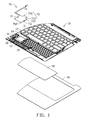
- FIG. 1 is an exploded, isometric view of one embodiment of a touch panel assembly.
- FIG. 2 is a partial, enlarged view of the portion II of FIG. 1 .
- FIG. 3 is similar to FIG. 1 , but viewed from another aspect.
- FIG. 4 is an assembled view of the touch panel assembly of FIG. 1 .
- FIG. 5 is a cross-sectional view of the touch panel assembly of FIG. 4 taken along a line V-V.
- FIG. 6 is a cross-sectional view of FIG. 4 taken along a line V-V, the soft board is being dismounted.
- FIGS. 1 , 2 , 3 show that a touch panel assembly includes an enclosure 10 , an outer panel 30 , a touch panel 50 , and a soft board 70 .
- the outer panel 30 is substantially parallel to the touch panel 50 .
- the enclosure 10 includes a positioning portion 12 .
- the positioning portion 12 includes a bottom portion 13 .
- the bottom portion 13 defines an opening 14 .
- the bottom portion 13 defines a first surface 131 and a second surface 133 substantially parallel to the first surface 131 .
- the positioning portion 12 further includes two hooks 15 extending from the first surface 131 and three positioning posts 16 extending from the first surface 131 .
- the opening 14 is located between the two hooks 15 .
- Each hook 15 includes a connecting portion 151 extending from the first surface 131 and an engaging portion 153 extending from the connecting portion 151 .
- the hook 15 is L-shaped.
- the connecting portion 151 is substantially perpendicular to the bottom portion 13 and the engaging portion 153 .
- the bottom portion 13 is substantially parallel to the touch panel 50 .
- the enclosure 10 further defines a slot 17 .
- the soft board 70 includes a board body 71 , a handling portion 73 extending from the board body 71 , and a chip 75 extending from the board body 71 .
- the chip 75 is configured to be received in the opening 14 .
- the board body 71 defines two securing holes 711 corresponding to the two hooks 15 , two first positioning holes 713 corresponding to the two positioning posts 16 , and a second positioning hole 715 .
- the securing hole 711 is square-shaped.
- the first positioning hole 713 and the second positioning hole 715 are circular.
- the handling portion 73 includes an extending portion 731 extending from the board body 71 and a resisting portion 733 extending from the extending portion 731 .
- the resisting portion 733 is arc-shaped.
- the resisting portion 733 is configured to be placed in the slot 17 .
- the board body 71 and the extending portion 731 are in the same plane and are substantially parallel to the bottom portion 13 .
- the width of the board body 71 is greater than the width of the extending portion 731 in the direction substantially parallel to the bottom portion 13 .
- FIGS. 4 to 6 show that in assembly, the touch panel 50 is placed on the second surface 133 of the bottom portion 13 of the positioning portion 12 .
- the outer panel 30 is placed on the touch panel 50 .
- the touch panel 50 and the outer panel 30 are glued together.
- the chip 75 of the soft board 70 is placed in the opening 14 .
- the two first positioning holes 713 of the soft board 70 are aligned with two of the positioning posts 16 .
- the soft board 70 moves close to the enclosure 10 to enable the two positioning posts 16 to pass through the two first positioning holes 713 .
- the resisting portion 733 is driven by external force to enable the board body 71 to be deformed, thereby enabling the securing holes 711 of the soft board 70 to be aligned with the hooks 15 of the positioning portion 12 .
- the board body 71 rebounds to drive the securing holes to receive the hooks 15 .
- the connecting portion 151 of each hook 15 contacts the edge of the securing hole 711 .
- the other positioning post 16 of the positioning portion 12 corresponds to the second positioning hole 715 of the soft board 70 .
- the soft board 70 is pressed downward to enable the other positioning post 16 to pass through the second positioning hole 715 .
- the resisting portion 733 passes through the slot 17 to contact the touch panel 50 .
- the resisting portion 733 has golden fingers (not shown).
- the touch panel 50 also has golden fingers (not shown). The golden fingers of the resisting portion 733 contact the golden fingers of the touch panel 50 to be electronically connected together.
- the positioning posts 16 are received in the first positioning hole 713 and the second positioning hole 715 , thereby preventing the soft board 70 from moving along a direction substantially parallel to the bottom portion 13 .
- the hooks 15 engage with the edges of the securing holes 711 to prevent the soft board 70 from moving a direction substantially perpendicular to the bottom portion 13 .
- FIG. 5 shows that in disassembly, the resisting portion 733 is driven by external force to enable the board body 71 to be deformed, thereby enabling the securing holes 711 to disengage the hooks 15 . And then the soft board 70 can be easily removed from the enclosure 10 .
Abstract
Description
Claims (17)
Applications Claiming Priority (2)
| Application Number | Priority Date | Filing Date | Title |
|---|---|---|---|
| TW102102745 | 2013-01-25 | ||
| TW102102745A TW201431466A (en) | 2013-01-25 | 2013-01-25 | Touch panel assembly |
Publications (2)
| Publication Number | Publication Date |
|---|---|
| US20140211391A1 US20140211391A1 (en) | 2014-07-31 |
| US9141149B2 true US9141149B2 (en) | 2015-09-22 |
Family
ID=51222699
Family Applications (1)
| Application Number | Title | Priority Date | Filing Date |
|---|---|---|---|
| US14/141,762 Expired - Fee Related US9141149B2 (en) | 2013-01-25 | 2013-12-27 | Touch panel assembly |
Country Status (3)
| Country | Link |
|---|---|
| US (1) | US9141149B2 (en) |
| JP (1) | JP2014146792A (en) |
| TW (1) | TW201431466A (en) |
Citations (19)
| Publication number | Priority date | Publication date | Assignee | Title |
|---|---|---|---|---|
| US5546334A (en) * | 1993-03-29 | 1996-08-13 | Acer Incorporated | Notebook computer system with a separable trackball |
| US5793355A (en) * | 1997-03-03 | 1998-08-11 | Compaq Computer Corporation | Portable computer with interchangeable pointing device modules |
| US5995082A (en) * | 1994-11-15 | 1999-11-30 | Lakoski; Robert P. | Removable pad for portable computer |
| US6025986A (en) * | 1997-12-18 | 2000-02-15 | Daniel I. Sternglass | Retractable palmrest for keyboard-equipped electronic products |
| US6219038B1 (en) * | 1997-08-06 | 2001-04-17 | Samsung Electronics Co., Ltd. | Water resistant touch pad for an electronic apparatus |
| US6262716B1 (en) * | 1998-07-01 | 2001-07-17 | Gateway, Inc. | Information processing apparatus having a numeric keypad with cover that functions as a palm rest |
| US6281887B1 (en) * | 1999-09-20 | 2001-08-28 | Mitac International Corp. | Touchpad assembly |
| US6388660B1 (en) * | 1997-12-31 | 2002-05-14 | Gateway, Inc. | Input pad integrated with a touch pad |
| US7068499B2 (en) * | 2001-06-25 | 2006-06-27 | Chrono Data Llc. | Modular computer user interface system |
| US20060201792A1 (en) * | 2005-03-14 | 2006-09-14 | Sun You M | Touch pad device for portable computer |
| US20070144885A1 (en) * | 2005-12-22 | 2007-06-28 | Kabushiki Kaisha Toshiba | Electronic apparatus |
| US7294805B2 (en) * | 2005-09-15 | 2007-11-13 | Inventec Corporation | Key structure applicable in an electronic device |
| US20080239641A1 (en) * | 2007-03-30 | 2008-10-02 | Kabushiki Kaisha Toshiba | Method of manufacturing electronic apparatus, electronic apparatus, and subassembly product |
| US20090009939A1 (en) * | 2005-04-18 | 2009-01-08 | Kabushiki Kaisha Toshiba | Battery unit |
| US7486278B2 (en) * | 2003-08-11 | 2009-02-03 | Lg Electronics Inc. | Touch pad device for portable computer |
| US7602604B2 (en) * | 2007-05-30 | 2009-10-13 | Kabushiki Kaisha Toshiba | Electronic apparatus |
| US20090304241A1 (en) * | 2008-06-05 | 2009-12-10 | Kabushiki Kaisha Toshiba | Electronic Apparatus |
| US8564938B2 (en) * | 2010-04-12 | 2013-10-22 | Kabushiki Kaisha Toshiba | Electronic apparatus |
| US9003315B2 (en) * | 2008-04-01 | 2015-04-07 | Litl Llc | System and method for streamlining user interaction with electronic content |
-
2013
- 2013-01-25 TW TW102102745A patent/TW201431466A/en unknown
- 2013-12-27 US US14/141,762 patent/US9141149B2/en not_active Expired - Fee Related
-
2014
- 2014-01-20 JP JP2014007527A patent/JP2014146792A/en active Pending
Patent Citations (19)
| Publication number | Priority date | Publication date | Assignee | Title |
|---|---|---|---|---|
| US5546334A (en) * | 1993-03-29 | 1996-08-13 | Acer Incorporated | Notebook computer system with a separable trackball |
| US5995082A (en) * | 1994-11-15 | 1999-11-30 | Lakoski; Robert P. | Removable pad for portable computer |
| US5793355A (en) * | 1997-03-03 | 1998-08-11 | Compaq Computer Corporation | Portable computer with interchangeable pointing device modules |
| US6219038B1 (en) * | 1997-08-06 | 2001-04-17 | Samsung Electronics Co., Ltd. | Water resistant touch pad for an electronic apparatus |
| US6025986A (en) * | 1997-12-18 | 2000-02-15 | Daniel I. Sternglass | Retractable palmrest for keyboard-equipped electronic products |
| US6388660B1 (en) * | 1997-12-31 | 2002-05-14 | Gateway, Inc. | Input pad integrated with a touch pad |
| US6262716B1 (en) * | 1998-07-01 | 2001-07-17 | Gateway, Inc. | Information processing apparatus having a numeric keypad with cover that functions as a palm rest |
| US6281887B1 (en) * | 1999-09-20 | 2001-08-28 | Mitac International Corp. | Touchpad assembly |
| US7068499B2 (en) * | 2001-06-25 | 2006-06-27 | Chrono Data Llc. | Modular computer user interface system |
| US7486278B2 (en) * | 2003-08-11 | 2009-02-03 | Lg Electronics Inc. | Touch pad device for portable computer |
| US20060201792A1 (en) * | 2005-03-14 | 2006-09-14 | Sun You M | Touch pad device for portable computer |
| US20090009939A1 (en) * | 2005-04-18 | 2009-01-08 | Kabushiki Kaisha Toshiba | Battery unit |
| US7294805B2 (en) * | 2005-09-15 | 2007-11-13 | Inventec Corporation | Key structure applicable in an electronic device |
| US20070144885A1 (en) * | 2005-12-22 | 2007-06-28 | Kabushiki Kaisha Toshiba | Electronic apparatus |
| US20080239641A1 (en) * | 2007-03-30 | 2008-10-02 | Kabushiki Kaisha Toshiba | Method of manufacturing electronic apparatus, electronic apparatus, and subassembly product |
| US7602604B2 (en) * | 2007-05-30 | 2009-10-13 | Kabushiki Kaisha Toshiba | Electronic apparatus |
| US9003315B2 (en) * | 2008-04-01 | 2015-04-07 | Litl Llc | System and method for streamlining user interaction with electronic content |
| US20090304241A1 (en) * | 2008-06-05 | 2009-12-10 | Kabushiki Kaisha Toshiba | Electronic Apparatus |
| US8564938B2 (en) * | 2010-04-12 | 2013-10-22 | Kabushiki Kaisha Toshiba | Electronic apparatus |
Also Published As
| Publication number | Publication date |
|---|---|
| JP2014146792A (en) | 2014-08-14 |
| TW201431466A (en) | 2014-08-01 |
| US20140211391A1 (en) | 2014-07-31 |
Similar Documents
| Publication | Publication Date | Title |
|---|---|---|
| US8624144B2 (en) | Push button cap mounting details | |
| US20120312943A1 (en) | Mounting apparatus for sliding drawer mechanism | |
| US20130050937A1 (en) | Fixing device for use with expansion cards in a computer | |
| US9354663B2 (en) | Portable electronic device | |
| US20130100622A1 (en) | Electronic device and fastening structure for circuit board | |
| US20110075348A1 (en) | Mounting apparatus for disk drive | |
| US20130162127A1 (en) | Electronic device enclosure | |
| US8742256B2 (en) | Electronic device enclosure | |
| US20140042114A1 (en) | Electronic device rack | |
| US20120194991A1 (en) | Expansion card and computer system with expansion card | |
| US8513521B2 (en) | Electronic device enclosure having a cable holding device | |
| US20120218704A1 (en) | Disk drive assembly | |
| US8599548B2 (en) | Mounting apparatus for PCI card bracket | |
| US9141149B2 (en) | Touch panel assembly | |
| US8936327B2 (en) | Bezel assembly for electronic device | |
| US20140078665A1 (en) | Data storage device assembly | |
| US20130322048A1 (en) | Fixing mechanism and electronic device using the same | |
| US20140184901A1 (en) | Mounting device for camera module | |
| US20120087083A1 (en) | Mounting apparatus for storage device | |
| US20150016879A1 (en) | Fastening device for backplane | |
| US20130147329A1 (en) | Chassis of electronic device with handle | |
| US20140160687A1 (en) | Electronic device enclosure | |
| US8630086B2 (en) | Hinged electronic device | |
| US9086857B2 (en) | Fastening device for expansion card | |
| US8733858B2 (en) | Computer enclosure |
Legal Events
| Date | Code | Title | Description |
|---|---|---|---|
| AS | Assignment |
Owner name: HON HAI PRECISION INDUSTRY CO., LTD., TAIWAN Free format text: ASSIGNMENT OF ASSIGNORS INTEREST;ASSIGNORS:TING, CHIA-WEI;HUNG, HAO-TING;REEL/FRAME:033427/0707 Effective date: 20131224 |
|
| STCF | Information on status: patent grant |
Free format text: PATENTED CASE |
|
| FEPP | Fee payment procedure |
Free format text: MAINTENANCE FEE REMINDER MAILED (ORIGINAL EVENT CODE: REM.); ENTITY STATUS OF PATENT OWNER: LARGE ENTITY |
|
| LAPS | Lapse for failure to pay maintenance fees |
Free format text: PATENT EXPIRED FOR FAILURE TO PAY MAINTENANCE FEES (ORIGINAL EVENT CODE: EXP.); ENTITY STATUS OF PATENT OWNER: LARGE ENTITY |
|
| STCH | Information on status: patent discontinuation |
Free format text: PATENT EXPIRED DUE TO NONPAYMENT OF MAINTENANCE FEES UNDER 37 CFR 1.362 |
|
| FP | Lapsed due to failure to pay maintenance fee |
Effective date: 20190922 |