US9153928B2 - Optical signal processing with modelocked lasers - Google Patents
Optical signal processing with modelocked lasers Download PDFInfo
- Publication number
- US9153928B2 US9153928B2 US12/895,127 US89512710A US9153928B2 US 9153928 B2 US9153928 B2 US 9153928B2 US 89512710 A US89512710 A US 89512710A US 9153928 B2 US9153928 B2 US 9153928B2
- Authority
- US
- United States
- Prior art keywords
- optical
- scanning laser
- laser system
- pulses
- oscillator
- Prior art date
- Legal status (The legal status is an assumption and is not a legal conclusion. Google has not performed a legal analysis and makes no representation as to the accuracy of the status listed.)
- Expired - Fee Related, expires
Links
- 230000003287 optical effect Effects 0.000 title claims description 254
- 238000012545 processing Methods 0.000 title description 14
- 230000001427 coherent effect Effects 0.000 claims abstract description 67
- 239000000835 fiber Substances 0.000 claims abstract description 55
- 230000009977 dual effect Effects 0.000 claims abstract description 34
- 230000003595 spectral effect Effects 0.000 claims description 71
- 238000005259 measurement Methods 0.000 claims description 69
- 238000001514 detection method Methods 0.000 claims description 48
- 238000005070 sampling Methods 0.000 claims description 45
- 239000006185 dispersion Substances 0.000 claims description 22
- 238000009615 fourier-transform spectroscopy Methods 0.000 claims description 21
- 230000003111 delayed effect Effects 0.000 claims description 19
- 238000000295 emission spectrum Methods 0.000 claims description 18
- 230000006641 stabilisation Effects 0.000 claims description 13
- 238000011105 stabilization Methods 0.000 claims description 13
- 238000000862 absorption spectrum Methods 0.000 claims description 12
- 230000001902 propagating effect Effects 0.000 claims description 11
- 230000003321 amplification Effects 0.000 claims description 9
- 238000003199 nucleic acid amplification method Methods 0.000 claims description 9
- 239000013307 optical fiber Substances 0.000 claims description 6
- 239000003381 stabilizer Substances 0.000 claims description 5
- 230000001419 dependent effect Effects 0.000 claims description 4
- 238000003384 imaging method Methods 0.000 abstract description 17
- 238000012634 optical imaging Methods 0.000 abstract description 9
- 238000000386 microscopy Methods 0.000 abstract description 6
- 238000001634 microspectroscopy Methods 0.000 abstract description 4
- 239000000523 sample Substances 0.000 description 143
- 238000001228 spectrum Methods 0.000 description 42
- 238000012360 testing method Methods 0.000 description 31
- 238000000034 method Methods 0.000 description 28
- 238000010521 absorption reaction Methods 0.000 description 27
- 238000004611 spectroscopical analysis Methods 0.000 description 26
- 230000035559 beat frequency Effects 0.000 description 21
- 230000006870 function Effects 0.000 description 21
- 238000001069 Raman spectroscopy Methods 0.000 description 20
- 238000010586 diagram Methods 0.000 description 20
- 230000005540 biological transmission Effects 0.000 description 17
- 238000012986 modification Methods 0.000 description 17
- 230000004048 modification Effects 0.000 description 17
- 230000010287 polarization Effects 0.000 description 17
- 230000004044 response Effects 0.000 description 17
- 230000035945 sensitivity Effects 0.000 description 17
- 238000012937 correction Methods 0.000 description 15
- 230000000875 corresponding effect Effects 0.000 description 15
- 238000013461 design Methods 0.000 description 12
- 239000007789 gas Substances 0.000 description 12
- 230000002452 interceptive effect Effects 0.000 description 10
- 238000012014 optical coherence tomography Methods 0.000 description 10
- 238000006243 chemical reaction Methods 0.000 description 9
- 230000009286 beneficial effect Effects 0.000 description 8
- 238000004847 absorption spectroscopy Methods 0.000 description 7
- BJQHLKABXJIVAM-UHFFFAOYSA-N bis(2-ethylhexyl) phthalate Chemical compound CCCCC(CC)COC(=O)C1=CC=CC=C1C(=O)OCC(CC)CCCC BJQHLKABXJIVAM-UHFFFAOYSA-N 0.000 description 7
- 230000010355 oscillation Effects 0.000 description 7
- 230000036962 time dependent Effects 0.000 description 7
- 238000012546 transfer Methods 0.000 description 7
- 238000001237 Raman spectrum Methods 0.000 description 6
- 238000004458 analytical method Methods 0.000 description 6
- 230000008859 change Effects 0.000 description 6
- 238000001914 filtration Methods 0.000 description 6
- 238000001208 nuclear magnetic resonance pulse sequence Methods 0.000 description 6
- 238000000926 separation method Methods 0.000 description 6
- 230000002123 temporal effect Effects 0.000 description 6
- 239000006096 absorbing agent Substances 0.000 description 5
- 210000001520 comb Anatomy 0.000 description 5
- 230000000087 stabilizing effect Effects 0.000 description 5
- 238000011144 upstream manufacturing Methods 0.000 description 5
- VYPSYNLAJGMNEJ-UHFFFAOYSA-N Silicium dioxide Chemical compound O=[Si]=O VYPSYNLAJGMNEJ-UHFFFAOYSA-N 0.000 description 4
- 235000010957 calcium stearoyl-2-lactylate Nutrition 0.000 description 4
- 230000006835 compression Effects 0.000 description 4
- 238000007906 compression Methods 0.000 description 4
- 239000013078 crystal Substances 0.000 description 4
- 230000006872 improvement Effects 0.000 description 4
- 230000003993 interaction Effects 0.000 description 4
- 238000012544 monitoring process Methods 0.000 description 4
- 230000008569 process Effects 0.000 description 4
- 238000001530 Raman microscopy Methods 0.000 description 3
- 238000010009 beating Methods 0.000 description 3
- 238000010276 construction Methods 0.000 description 3
- 230000001934 delay Effects 0.000 description 3
- 238000004993 emission spectroscopy Methods 0.000 description 3
- 238000010348 incorporation Methods 0.000 description 3
- 230000000704 physical effect Effects 0.000 description 3
- 230000009467 reduction Effects 0.000 description 3
- 230000002269 spontaneous effect Effects 0.000 description 3
- 238000004416 surface enhanced Raman spectroscopy Methods 0.000 description 3
- 229910052691 Erbium Inorganic materials 0.000 description 2
- 229910052775 Thulium Inorganic materials 0.000 description 2
- 229910052769 Ytterbium Inorganic materials 0.000 description 2
- 230000008901 benefit Effects 0.000 description 2
- 229910052797 bismuth Inorganic materials 0.000 description 2
- 238000004364 calculation method Methods 0.000 description 2
- 238000012512 characterization method Methods 0.000 description 2
- 230000002596 correlated effect Effects 0.000 description 2
- 230000007613 environmental effect Effects 0.000 description 2
- 238000002474 experimental method Methods 0.000 description 2
- 230000010354 integration Effects 0.000 description 2
- 238000004476 mid-IR spectroscopy Methods 0.000 description 2
- 238000002156 mixing Methods 0.000 description 2
- 239000004038 photonic crystal Substances 0.000 description 2
- 230000005855 radiation Effects 0.000 description 2
- 238000012163 sequencing technique Methods 0.000 description 2
- 239000000377 silicon dioxide Substances 0.000 description 2
- 230000001960 triggered effect Effects 0.000 description 2
- 0 *CCCCCC=*1CCCC1 Chemical compound *CCCCCC=*1CCCC1 0.000 description 1
- KRHYYFGTRYWZRS-UHFFFAOYSA-M Fluoride anion Chemical compound [F-] KRHYYFGTRYWZRS-UHFFFAOYSA-M 0.000 description 1
- 229910001218 Gallium arsenide Inorganic materials 0.000 description 1
- 229910052689 Holmium Inorganic materials 0.000 description 1
- 238000004566 IR spectroscopy Methods 0.000 description 1
- 229910003327 LiNbO3 Inorganic materials 0.000 description 1
- 229910052779 Neodymium Inorganic materials 0.000 description 1
- 230000006978 adaptation Effects 0.000 description 1
- 238000013459 approach Methods 0.000 description 1
- 238000005311 autocorrelation function Methods 0.000 description 1
- 230000004888 barrier function Effects 0.000 description 1
- UHOVQNZJYSORNB-UHFFFAOYSA-N c1ccccc1 Chemical compound c1ccccc1 UHOVQNZJYSORNB-UHFFFAOYSA-N 0.000 description 1
- 150000004770 chalcogenides Chemical class 0.000 description 1
- 238000000701 chemical imaging Methods 0.000 description 1
- 238000002082 coherent anti-Stokes Raman spectroscopy Methods 0.000 description 1
- 230000001143 conditioned effect Effects 0.000 description 1
- 230000001276 controlling effect Effects 0.000 description 1
- 125000004122 cyclic group Chemical group 0.000 description 1
- 230000000694 effects Effects 0.000 description 1
- 230000005684 electric field Effects 0.000 description 1
- 230000005670 electromagnetic radiation Effects 0.000 description 1
- 238000005516 engineering process Methods 0.000 description 1
- 230000005284 excitation Effects 0.000 description 1
- 238000000605 extraction Methods 0.000 description 1
- 238000002789 length control Methods 0.000 description 1
- 230000005923 long-lasting effect Effects 0.000 description 1
- 230000007774 longterm Effects 0.000 description 1
- 239000000463 material Substances 0.000 description 1
- 230000000644 propagated effect Effects 0.000 description 1
- 230000006798 recombination Effects 0.000 description 1
- 238000005215 recombination Methods 0.000 description 1
- 238000011896 sensitive detection Methods 0.000 description 1
- 238000001774 stimulated Raman spectroscopy Methods 0.000 description 1
- 238000006467 substitution reaction Methods 0.000 description 1
- 230000001629 suppression Effects 0.000 description 1
- 238000013519 translation Methods 0.000 description 1
Images


Classifications
-
- H—ELECTRICITY
- H01—ELECTRIC ELEMENTS
- H01S—DEVICES USING THE PROCESS OF LIGHT AMPLIFICATION BY STIMULATED EMISSION OF RADIATION [LASER] TO AMPLIFY OR GENERATE LIGHT; DEVICES USING STIMULATED EMISSION OF ELECTROMAGNETIC RADIATION IN WAVE RANGES OTHER THAN OPTICAL
- H01S3/00—Lasers, i.e. devices using stimulated emission of electromagnetic radiation in the infrared, visible or ultraviolet wave range
- H01S3/10—Controlling the intensity, frequency, phase, polarisation or direction of the emitted radiation, e.g. switching, gating, modulating or demodulating
- H01S3/11—Mode locking; Q-switching; Other giant-pulse techniques, e.g. cavity dumping
- H01S3/1106—Mode locking
-
- H—ELECTRICITY
- H01—ELECTRIC ELEMENTS
- H01S—DEVICES USING THE PROCESS OF LIGHT AMPLIFICATION BY STIMULATED EMISSION OF RADIATION [LASER] TO AMPLIFY OR GENERATE LIGHT; DEVICES USING STIMULATED EMISSION OF ELECTROMAGNETIC RADIATION IN WAVE RANGES OTHER THAN OPTICAL
- H01S3/00—Lasers, i.e. devices using stimulated emission of electromagnetic radiation in the infrared, visible or ultraviolet wave range
- H01S3/05—Construction or shape of optical resonators; Accommodation of active medium therein; Shape of active medium
- H01S3/06—Construction or shape of active medium
- H01S3/063—Waveguide lasers, i.e. whereby the dimensions of the waveguide are of the order of the light wavelength
- H01S3/067—Fibre lasers
-
- G—PHYSICS
- G01—MEASURING; TESTING
- G01J—MEASUREMENT OF INTENSITY, VELOCITY, SPECTRAL CONTENT, POLARISATION, PHASE OR PULSE CHARACTERISTICS OF INFRARED, VISIBLE OR ULTRAVIOLET LIGHT; COLORIMETRY; RADIATION PYROMETRY
- G01J3/00—Spectrometry; Spectrophotometry; Monochromators; Measuring colours
- G01J3/02—Details
- G01J3/10—Arrangements of light sources specially adapted for spectrometry or colorimetry
-
- G—PHYSICS
- G01—MEASURING; TESTING
- G01J—MEASUREMENT OF INTENSITY, VELOCITY, SPECTRAL CONTENT, POLARISATION, PHASE OR PULSE CHARACTERISTICS OF INFRARED, VISIBLE OR ULTRAVIOLET LIGHT; COLORIMETRY; RADIATION PYROMETRY
- G01J3/00—Spectrometry; Spectrophotometry; Monochromators; Measuring colours
- G01J3/28—Investigating the spectrum
- G01J3/45—Interferometric spectrometry
-
- G—PHYSICS
- G01—MEASURING; TESTING
- G01N—INVESTIGATING OR ANALYSING MATERIALS BY DETERMINING THEIR CHEMICAL OR PHYSICAL PROPERTIES
- G01N21/00—Investigating or analysing materials by the use of optical means, i.e. using sub-millimetre waves, infrared, visible or ultraviolet light
- G01N21/17—Systems in which incident light is modified in accordance with the properties of the material investigated
- G01N21/25—Colour; Spectral properties, i.e. comparison of effect of material on the light at two or more different wavelengths or wavelength bands
- G01N21/31—Investigating relative effect of material at wavelengths characteristic of specific elements or molecules, e.g. atomic absorption spectrometry
- G01N21/35—Investigating relative effect of material at wavelengths characteristic of specific elements or molecules, e.g. atomic absorption spectrometry using infrared light
- G01N21/3581—Investigating relative effect of material at wavelengths characteristic of specific elements or molecules, e.g. atomic absorption spectrometry using infrared light using far infrared light; using Terahertz radiation
-
- G—PHYSICS
- G01—MEASURING; TESTING
- G01N—INVESTIGATING OR ANALYSING MATERIALS BY DETERMINING THEIR CHEMICAL OR PHYSICAL PROPERTIES
- G01N21/00—Investigating or analysing materials by the use of optical means, i.e. using sub-millimetre waves, infrared, visible or ultraviolet light
- G01N21/17—Systems in which incident light is modified in accordance with the properties of the material investigated
- G01N21/47—Scattering, i.e. diffuse reflection
- G01N21/4795—Scattering, i.e. diffuse reflection spatially resolved investigating of object in scattering medium
-
- G—PHYSICS
- G01—MEASURING; TESTING
- G01N—INVESTIGATING OR ANALYSING MATERIALS BY DETERMINING THEIR CHEMICAL OR PHYSICAL PROPERTIES
- G01N21/00—Investigating or analysing materials by the use of optical means, i.e. using sub-millimetre waves, infrared, visible or ultraviolet light
- G01N21/62—Systems in which the material investigated is excited whereby it emits light or causes a change in wavelength of the incident light
- G01N21/63—Systems in which the material investigated is excited whereby it emits light or causes a change in wavelength of the incident light optically excited
- G01N21/636—Systems in which the material investigated is excited whereby it emits light or causes a change in wavelength of the incident light optically excited using an arrangement of pump beam and probe beam; using the measurement of optical non-linear properties
-
- G—PHYSICS
- G01—MEASURING; TESTING
- G01N—INVESTIGATING OR ANALYSING MATERIALS BY DETERMINING THEIR CHEMICAL OR PHYSICAL PROPERTIES
- G01N21/00—Investigating or analysing materials by the use of optical means, i.e. using sub-millimetre waves, infrared, visible or ultraviolet light
- G01N21/62—Systems in which the material investigated is excited whereby it emits light or causes a change in wavelength of the incident light
- G01N21/63—Systems in which the material investigated is excited whereby it emits light or causes a change in wavelength of the incident light optically excited
- G01N21/65—Raman scattering
-
- H—ELECTRICITY
- H01—ELECTRIC ELEMENTS
- H01S—DEVICES USING THE PROCESS OF LIGHT AMPLIFICATION BY STIMULATED EMISSION OF RADIATION [LASER] TO AMPLIFY OR GENERATE LIGHT; DEVICES USING STIMULATED EMISSION OF ELECTROMAGNETIC RADIATION IN WAVE RANGES OTHER THAN OPTICAL
- H01S3/00—Lasers, i.e. devices using stimulated emission of electromagnetic radiation in the infrared, visible or ultraviolet wave range
- H01S3/10—Controlling the intensity, frequency, phase, polarisation or direction of the emitted radiation, e.g. switching, gating, modulating or demodulating
- H01S3/11—Mode locking; Q-switching; Other giant-pulse techniques, e.g. cavity dumping
- H01S3/1106—Mode locking
- H01S3/1112—Passive mode locking
- H01S3/1115—Passive mode locking using intracavity saturable absorbers
-
- G—PHYSICS
- G01—MEASURING; TESTING
- G01J—MEASUREMENT OF INTENSITY, VELOCITY, SPECTRAL CONTENT, POLARISATION, PHASE OR PULSE CHARACTERISTICS OF INFRARED, VISIBLE OR ULTRAVIOLET LIGHT; COLORIMETRY; RADIATION PYROMETRY
- G01J3/00—Spectrometry; Spectrophotometry; Monochromators; Measuring colours
- G01J3/02—Details
- G01J3/10—Arrangements of light sources specially adapted for spectrometry or colorimetry
- G01J2003/102—Plural sources
-
- G—PHYSICS
- G01—MEASURING; TESTING
- G01N—INVESTIGATING OR ANALYSING MATERIALS BY DETERMINING THEIR CHEMICAL OR PHYSICAL PROPERTIES
- G01N21/00—Investigating or analysing materials by the use of optical means, i.e. using sub-millimetre waves, infrared, visible or ultraviolet light
- G01N21/17—Systems in which incident light is modified in accordance with the properties of the material investigated
- G01N21/25—Colour; Spectral properties, i.e. comparison of effect of material on the light at two or more different wavelengths or wavelength bands
- G01N21/31—Investigating relative effect of material at wavelengths characteristic of specific elements or molecules, e.g. atomic absorption spectrometry
- G01N21/35—Investigating relative effect of material at wavelengths characteristic of specific elements or molecules, e.g. atomic absorption spectrometry using infrared light
- G01N2021/3595—Investigating relative effect of material at wavelengths characteristic of specific elements or molecules, e.g. atomic absorption spectrometry using infrared light using FTIR
-
- H—ELECTRICITY
- H01—ELECTRIC ELEMENTS
- H01S—DEVICES USING THE PROCESS OF LIGHT AMPLIFICATION BY STIMULATED EMISSION OF RADIATION [LASER] TO AMPLIFY OR GENERATE LIGHT; DEVICES USING STIMULATED EMISSION OF ELECTROMAGNETIC RADIATION IN WAVE RANGES OTHER THAN OPTICAL
- H01S3/00—Lasers, i.e. devices using stimulated emission of electromagnetic radiation in the infrared, visible or ultraviolet wave range
- H01S3/10—Controlling the intensity, frequency, phase, polarisation or direction of the emitted radiation, e.g. switching, gating, modulating or demodulating
- H01S3/105—Controlling the intensity, frequency, phase, polarisation or direction of the emitted radiation, e.g. switching, gating, modulating or demodulating by controlling the mutual position or the reflecting properties of the reflectors of the cavity, e.g. by controlling the cavity length
-
- H—ELECTRICITY
- H01—ELECTRIC ELEMENTS
- H01S—DEVICES USING THE PROCESS OF LIGHT AMPLIFICATION BY STIMULATED EMISSION OF RADIATION [LASER] TO AMPLIFY OR GENERATE LIGHT; DEVICES USING STIMULATED EMISSION OF ELECTROMAGNETIC RADIATION IN WAVE RANGES OTHER THAN OPTICAL
- H01S3/00—Lasers, i.e. devices using stimulated emission of electromagnetic radiation in the infrared, visible or ultraviolet wave range
- H01S3/10—Controlling the intensity, frequency, phase, polarisation or direction of the emitted radiation, e.g. switching, gating, modulating or demodulating
- H01S3/106—Controlling the intensity, frequency, phase, polarisation or direction of the emitted radiation, e.g. switching, gating, modulating or demodulating by controlling devices placed within the cavity
- H01S3/1068—Controlling the intensity, frequency, phase, polarisation or direction of the emitted radiation, e.g. switching, gating, modulating or demodulating by controlling devices placed within the cavity using an acousto-optical device
-
- H—ELECTRICITY
- H01—ELECTRIC ELEMENTS
- H01S—DEVICES USING THE PROCESS OF LIGHT AMPLIFICATION BY STIMULATED EMISSION OF RADIATION [LASER] TO AMPLIFY OR GENERATE LIGHT; DEVICES USING STIMULATED EMISSION OF ELECTROMAGNETIC RADIATION IN WAVE RANGES OTHER THAN OPTICAL
- H01S3/00—Lasers, i.e. devices using stimulated emission of electromagnetic radiation in the infrared, visible or ultraviolet wave range
- H01S3/10—Controlling the intensity, frequency, phase, polarisation or direction of the emitted radiation, e.g. switching, gating, modulating or demodulating
- H01S3/106—Controlling the intensity, frequency, phase, polarisation or direction of the emitted radiation, e.g. switching, gating, modulating or demodulating by controlling devices placed within the cavity
- H01S3/107—Controlling the intensity, frequency, phase, polarisation or direction of the emitted radiation, e.g. switching, gating, modulating or demodulating by controlling devices placed within the cavity using electro-optic devices, e.g. exhibiting Pockels or Kerr effect
Definitions
- the invention relates to the application of optical signal processing to mode locked lasers for precision sensing, sampling and spectroscopy.
- Mode locked lasers and frequency comb lasers have provided for advancements in spectroscopy and precision sensing.
- a mode locked laser was recently combined with a conventional Fourier transform spectrometer (FTS) to obtain an improved signal/noise ratio for spectral absorption measurements (J. Mandon et al., ‘Fourier transform spectroscopy with a laser frequency comb’, in Nature Photonics, vol. 3, pp. 99-102, 2009) and N. Picque' et al., International Patent Application, Publication WO 2010/010437.
- the use of a frequency comb laser for spectroscopy was suggested by Haensch et al. in U.S. Pat. No. 7,203,402.
- frequency comb lasers require precise control of the repetition rate and carrier envelope offset frequency.
- frequency measurements can be performed without stabilization of individual comb lines by the use of a modelocked laser as a transfer oscillator (J. Stenger et al., Phys. Rev. Lett., vol. 7, pp. 073601-1-073601-4, (2002)).
- modelocked lasers as transfer oscillators, frequency ratios or frequency differences between two reference frequencies located in widely separated regions of the optical spectrum (limited only by the spectral extent of the spectral coverage of the modelocked lasers) can be precisely measured.
- cw reference lasers can be used to effectively stabilize the differences between the carrier envelope offset frequencies of two modelocked lasers. This information can then be used for spectral calibration of a FTS for spectral absorption measurements constructed from the two modelocked lasers with a resolution limit corresponding approximately to the repetition rate of the modelocked lasers. As described in '435, such dual modelocked lasers are referred to as coherent dual scanning lasers or CDSLs. Moreover, CDSLs based on high repetition rates allow for high scan rates which are beneficial for rapid signal acquisition. CDSLs based on fiber supercontinuum sources further allow very broad spectral coverage for an FTS and other applications.
- two narrow linewidth cw reference lasers can be used to track the difference between the carrier envelope offset frequencies and repetition rates of two mode locked lasers, as disclosed by P. Giacarri et al., ‘Referencing of the beating spectra of frequency combs’ (International Patent Application, Publication WO 2009/000079) without the need for carrier envelope offset frequency control.
- the resolution of this scheme is also limited to the repetition rate of the mode locked lasers, assuming for example that a reference laser is located in between two comb lines and the absolute frequency of the reference laser or the absolute order m of the comb lines is not known.
- relatively low repetition rate lasers are implemented which leads to slow data acquisition rates.
- the beat signal between two comb lines from two separate comb lasers can be directly measured via the implementation of a cw transfer oscillator. Repetition rate fluctuations between the two comb lasers can then be recorded and these recorded repetition rate fluctuations can then be used to simultaneously correct an interferogram between the two comb lasers via implementing a new sampling grid with equidistant optical path length differences (G. Guelachvili et al., World patent application, WO 2010/010444).
- this scheme ideally also uses measurements of the carrier-envelope offset frequencies of the two comb lasers or alternatively implements a second cw laser with a different frequency to which two other comb lines are locked.
- Hertz-level resolution in a FTS has been achieved using two frequency comb lasers which are phase locked to two cw lasers which were in turn locked to two high finesse reference cavities as discussed in I. Coddington et al., ‘Coherent multiheterodyne spectroscopy using stabilized comb sources’, Phys. Rev. Lett., vol. 100, pp. 013902 (2008); henceforth ‘Coddington’.
- such a scheme requires at least 4 phase locked loops for locking of the frequency comb lasers to the two cw optical clock lasers, plus additional phase locked loops for stabilization of the cw lasers to the reference cavities.
- the achieved Hz level resolution is generally not required in real-world optical spectroscopy, where Doppler broadened absorption lines of line width ⁇ 5 ⁇ 10 ⁇ 7 ⁇ x at a frequency of ⁇ x are typically encountered. For example, in the visible spectral region ⁇ 300 MHz.
- Rapidly scanning CDSLs are disclosed based on mode locked lasers for various applications, for example, high resolution, high sensitivity FTS and micro-spectroscopy, optical imaging, sampling and light detection and ranging (LIDAR).
- LIDAR light detection and ranging
- Various high resolution CDSL embodiments include first and second mode locked oscillators operated at slightly different repetition rates, each mode locked oscillator having a carrier envelope offset frequency. Outputs of the first and second mode locked oscillators, in combination with outputs from two reference lasers, are used to generate signals for stabilizing differences between both the carrier envelope offset frequencies and differences between the repetition rates of the two mode locked oscillators.
- the carrier envelope offset frequency of at least one oscillator may also be derived from the signals, resulting in a resolution corresponding to at least the bandwidth of the reference lasers and further allowing for Hertz level frequency resolution.
- Various high resolution CDSLs are useable in systems for phase, absorption, emission and/or spectral measurement.
- Various embodiments provide high resolution FTS by utilizing a combination of optical phase-locking with optical referencing.
- the difference frequencies of two next neighbor comb lines from two mode locked lasers are phase-locked with at least two phase-locked loops using two cw reference lasers.
- frequency locking schemes can also be implemented. Tracking of the beat frequencies of the two cw reference lasers with the individual comb lines further allows absolute frequency calibration of the FTS.
- Various embodiments provide high resolution FTS by recording multiple adjacent interferograms, which increases the resolution of a FTS proportional to the signal acquisition time.
- phase error output of the phase-locked loops can be used to produce correction signals to various frequency parameters defining the operation of the mode locked lasers.
- Various embodiments provide high sensitivity, low noise FTS with broad spectral coverage by implementing frequency conversion schemes to expand spectral coverage, and dual balanced detection schemes for noise suppression.
- a dual balanced detection scheme can utilize the interference of two mode locked lasers, which are combined at a beam-splitter.
- the two mode-locked lasers can be amplified and spectrally broadened along two orthogonal polarization axes in an optical fiber system and subsequently combined via a beam-splitter.
- Various embodiments provide high sensitivity FTS by the adaptation of enhancement cavities incorporated into the beam path of one mode locked laser. Locking to the enhancement cavities can be performed by frequency shifting of the laser spectra with appropriate optical frequency shifters or by tuning the cavity.
- FTS can be implemented for the measurement of phase, absorption and emission spectra of optical samples located inside the beam path of the two mode locked lasers.
- Emission spectral measurements can be used for the measurement of spontaneous and stimulated Raman emission spectra from optical samples, enhancement of Raman emission can further be implemented for improved signal/noise ratios and optical imaging and optical scanning can be implemented for the measurement of spatially resolved Raman spectra.
- CDLS can also be used for signal characterization via linear optical sampling.
- CDLS can further be used to measure the phase response of a test sample to a strong pump pulse in a pump probe configuration.
- CDLS can further be used for two and multi-dimensional emission and absorption spectroscopy of a test sample.
- CDSLs can further be implemented in optical coherence tomography by measurement of the time dependent reflection from a sample, where preferably the measurement is performed at the fundamental interferometric beat frequency of the two mode locked lasers.
- Depth resolved imaging can also be performed in the THz domain by using the two mode locked lasers in a pump probe arrangement.
- the difference in carrier envelope offset frequencies and repetition rates of a CDSL is controlled by locking two next neighbor comb lines from two mode locked lasers to at least one cw reference laser.
- the resolution of a FTS based on CDSL is increased proportional to the signal acquisition time by minimizing fluctuations of the effective scan rate during the signal acquisition time.
- dual balanced detection improves the signal/noise ratio of a FTS.
- the sensitivity of a FTS based on CDSL is increased with the use of an external cavity.
- phase and absorption spectra are measured using an FTS based on a CDSL.
- Embodiments may be adapted for OCT (optical coherence tomography), THz imaging, or similar applications.
- a CDSL is integrated with existing FTS equipment, which may include one or more of positioning equipment for samples to be probed, detection equipment, and signal processing equipment which may include digital and/or analog signal processors, computers, and/or various signal processing software algorithms.
- an effective CDSL may be constructed with only one laser.
- At least one embodiment includes a coherent scanning laser system (CSL) for generating pulse pairs with a time varying time delay.
- the system includes an optical source that generates optical pulses at a time-varying repetition rate, and a repetition rate modulator to modulate the repetition rate at a modulation rate.
- the source generates an output that includes the pulse pairs.
- the system also includes an optical reference for generating a reference signal for measurement of at least the time delay between the two pulses of the pulse pair as a function of time.
- FIG. 1 is a diagram schematically illustrating high resolution FTS based on a CDSL.
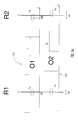
- FIG. 1A schematically illustrates a portion of the spectra of two mode locked lasers and two reference oscillators, and beat frequencies derived therefrom for monitoring and/or stabilizing a CDSL.
- FIG. 1B schematically illustrates an arrangement for a high resolution FTS based on a CDSL.
- FIG. 2 is a schematic representation of sample and detector locations for sample absorption measurement with a CDSL.
- FIG. 3 is a plot illustrating three adjacent interferograms obtainable with a CDSL.
- FIG. 4 is a schematic diagram illustrating dual balanced detection in a FTS based on a CDSL.
- FIG. 5 is a schematic diagram of an arrangement for measuring the absorption and phase response of a sample in a FTS based on a CDSL.
- FIG. 6 is a schematic diagram of an alternative arrangement for measuring the absorption and phase response of a sample in a FTS based on a CDSL.
- FIG. 7 is a schematic diagram of an enhancement cavity for improved sensitivity of absorption and phase measurements using a FTS based on a CDSL.
- FIG. 8 is a schematic diagram of an arrangement used for obtaining spatially resolved emission spectra from a sample.
- FIG. 9 is a schematic diagram of an arrangement for obtaining spatially resolved stimulated Raman emission spectra from a sample.
- FIG. 10 is a schematic diagram of an arrangement for coherent anti-Stokes Raman spectroscopy.
- FIG. 11 is schematic diagram of a CDSL used in linear optical sampling.
- FIG. 12 is a schematic diagram of a CDSL in a pump probe configuration.
- FIG. 12A is a schematic diagram illustrating the use of a CDSL in a two dimensional spectroscopy measurement.
- FIG. 13 is a schematic diagram illustrating the use of a CDSL in optical coherence tomography.
- FIG. 14 is a schematic diagram illustrating a CDSL in THz ranging.
- FIG. 15 is a schematic diagram illustrating a CDSL in THz spectroscopy and spectroscopic imaging.
- FIG. 16 is a schematic diagram illustrating an effective CDSL constructed with only one laser.
- FIG. 16 a is a schematic diagram illustrating the generic design of a CSL including an optical reference.
- FIG. 17A is a diagram schematically illustrating a mode locked oscillator design suitable for use in a CSL incorporating optical referencing with an external laser.
- FIG. 17B is a diagram schematically illustrating an alternative mode locked oscillator design suitable for use in a CSL incorporating optical referencing with an external laser.
- FIG. 18 is a diagram illustrating in-phase (triangles up) and quadrature-phase (triangles down) reference signals as well as their ratio (square) obtainable from a reference interferometer configured to probe the mirror position of a repetition rate modulated mode locked oscillator.
- FIG. 19 is a schematic representation of a FTS based on a CSL including optical referencing.
- FIG. 19A is a schematic representation of an electronic scheme for centering the zero-delay point during repetition rate dithering.
- FIG. 19B is a series of plots illustrating various signals for centering the zero-delay point during repetition rate dithering in relation to the actual cavity length modulation.
- FIG. 20 is a schematic representation of a CDSL including an optical reference configured for FTS.
- FIG. 21 is a schematic representation of a CDSL incorporating repetition rate multiplication.
- FIG. 22 is a schematic representation of a CDSL for pump probe experiments and imaging incorporating repetition rate multiplication.
- FIG. 23 is a schematic representation of a CSL for two-dimensional spectroscopy applications.
- FIG. 24 is a schematic diagram illustrating an alternative embodiment of an effective CSL constructed with only one laser including optical referencing.
- FIG. 25 is a plot illustrating a measurement of an interferogram recorded with a CSL.
- FIG. 26 is a plot illustrating measurement of a frequency spectrum of an interferogram recorded with a CSL (thin line) and of a corrected frequency spectrum (thick line) accounting for fluctuations in intra-cavity mirror velocity.
- CDSL systems and applications Some examples of CDSL systems and applications are disclosed below. Implementations providing for one or more of high resolution, high acquisition rate, high sensitivity, low-noise, and a high-level of integration are described. Non-linear spectral generation and various implementations for phase-control lead to stable output signals in the near-IR range, thereby providing benefits for IR absorption and emission spectroscopy, THz imaging and ranging applications.
- FIG. 1 schematically illustrates a coherent dual scanning laser system 100 (CDSL) according to an embodiment for Fourier transform absorption spectroscopy.
- CDSL coherent dual scanning laser system 100
- output of CDSL 100 is directed to a sample to be measured.
- a Fourier transform spectrometer (FTS) probes a physical property of the sample using spectral information in the emission envelope of the CDSL.
- FTS Fourier transform spectrometer
- CDSL 100 comprises two mode locked lasers (oscillator O 1 and oscillator O 2 ) and two cw reference lasers (R 1 and R 2 ). Each oscillator produces outputs that are combined with outputs from each of the reference lasers, which may be CW lasers.
- FIG. 1B schematically illustrates a portion of the spectra 110 , 120 corresponding to outputs from O 1 and O 2 , respectively.
- O 1 and O 2 have slightly different repetition rates f r1 , f r2 , and the frequency lines of O 1 and O 2 are separated by the respective repetition rates.
- Certain frequency lines of O 1 ,O 2 are spaced apart from immediately adjacent frequencies f x , f y of the cw reference lasers as shown.
- beat frequencies f b1 , f b2 , f b3 , and f b4 , and difference frequencies ⁇ f 2 and ⁇ f 1 thereof are derived from O 1 and O 2 and adjacent frequency lines of R 1 and R 2 .
- the signals are detected with photodetectors so as to monitor and/or stabilize the CDSL.
- a control system which may include a phase locked loop and analog and/or digital signal processors, may be used to monitor and/or stabilize the CDSL.
- the outputs of oscillators O 1 ,O 2 and cw reference laser R 1 are combined via two fiber optic couplers C 1 and C 2 , respectively.
- An additional fiber optic coupler C 3 splits the output of reference laser R 1 and directs the R 1 output to couplers C 1 and C 2 .
- the beat frequency between a frequency line of oscillator O 1 and cw laser R 1 , f b1 is detected with detector D 1 .
- the beat frequency between a frequency line of oscillator O 2 and cw laser R 1 , f b2 is detected with detector D 2 .
- ⁇ f 2 can further be stabilized by appropriately varying the cavity length of O 2 via phase locking of ⁇ f 2 to an external RF reference (not shown).
- analog or digital phase locked loops can be implemented.
- the beat frequencies f b1 to f b4 are also digitized.
- f b1 and f b2 can both be locked individually to external RF references using for example cavity length or oscillator pump power control of one or the other oscillator, which also stabilizes ⁇ f 2 .
- Locking of a cw reference laser to two mode locked lasers for the construction of a CDSL was for example discussed in '435.
- beat signals can be observed when the comb lines are on either side of f x and f y respectively.
- This ambiguity can be eliminated by the use of optical single side-band (SSB) mixers, which suppress the beat signals on one side of f x and f y .
- SSB optical single side-band
- an optical SSB mixer can suppress f b1 and f b3 in FIG. 1A , while passing f b2 and f b4 .
- the comb lines have thus to be shifted to be on the right side of f x and f y respectively.
- SSB mixers simplify the required locking electronics and the interpretation of the observed beat signals.
- Optical SSB mixers are well known in the state of the art and are, for example, shown in FIG. 10.4 of ‘Building Electro-Optical Systems’ by P. C. D. Hobbs, John Wiley&Sons (2000) and are not further described here.
- the incorporation of SSB mixers in FIG. 1 requires the substitution of each of the four detectors D 1 -D 4 in FIG. 1 with a set of two pairs of balanced detectors (resulting in a total of 8 balanced detector pairs) for in-phase detection and quadrature detection of the respective beat signals.
- Fiber optic beam paths and couplers provide for a high level of integration.
- free-space beam paths and beamsplitters may be implemented, alone or in combination with fiber technology.
- mode locked fiber lasers are implemented as oscillators O 1 and O 2 , although solid-state laser oscillators and diode lasers may be used in various embodiments, alone or in combination with fiber oscillators.
- a sample and FTS detection unit as illustrated in FIG. 1 is shown in more detail in the example of FIG. 2 .
- the outputs of the two oscillators O 1 , O 2 are combined via beamsplitter B 1 (or an equivalent fiber optic coupler) in order to construct a FTS for absorption spectroscopy.
- a second beam splitter B 2 allows for the detection of a reference spectrum via detector D 5 .
- the absorption spectrum of a sample inserted in front of detector D 6 is measured using the output of detector D 6 .
- Signal processing equipment, SP may be utilized in the FTS to condition signals from the detectors and process the information obtained from the detectors. Schemes for obtaining the absorption spectrum via a FTS based on a CDSL were also discussed in '435.
- n and m can be obtained for example via absolute frequency measurements using a separate comb laser.
- f ceo1 or f ceo2 are measured. In at least one embodiment this can be performed with an f-2f interferometer.
- f ceo1 can be obtained from
- f ceo ⁇ ⁇ 1 n ⁇ ( f y + f b ⁇ ⁇ 3 ) - m ⁇ ( f x + f b ⁇ ⁇ 1 ) n - m . ( 7 )
- f ceo1 can be obtained from recording f b3 and f b1 in addition to stabilizing ⁇ f 1 and ⁇ f 2 .
- f ceo1 can be recorded during the acquisition time ⁇ of an interferogram and the interferogram can then be multiplied with a phase correction term
- O opt exp [ - i ⁇ ( ⁇ f rep ) ⁇ ⁇ 0 ⁇ ⁇ f ceo ⁇ ⁇ 1 ⁇ ( t ) ⁇ ⁇ d t ] .
- f opt [f rf ⁇ f ceo ]f rep / ⁇ (9) as also explained in '435.
- the usable signal acquisition time in FTS can be regarded as being limited by the coherence time of the cw references.
- f rep can be locked to an external frequency reference, which can for example be done via modulating the pump current to one of the mode locked lasers.
- f rep can be recorded and an additional phase correction term can be added to eq. (8). Because the cw lasers can be locked to optical clocks and coherence times of the order of seconds can be achieved, Hertz level frequency resolution can be achieved. Thus, frequency resolution very much smaller than the repetition rate of the mode locked lasers is obtainable.
- ⁇ f 1 and ⁇ f 2 can be stabilized by locking optical beat signals generated by overlap between individual comb lines and a cw reference laser to external RF references.
- ⁇ f 1 and ⁇ f 2 can be stabilized by using cw reference lasers as transfer oscillators and locking the difference frequency of two comb lines from two different modelocked lasers to external RF references. Any combination of these two methods is also possible.
- ⁇ f 1 and ⁇ f 2 can further be directly measured and stabilized by isolating two individual comb lines from the two comb lasers via optical filtering and measuring the resulting beat signal.
- Optical filters can, for example, be conveniently constructed from fiber Bragg gratings or Fabry-Perot etalons or a combination of both.
- FIG. 1B An example of a scheme for locking ⁇ f 1 and ⁇ f 2 with optical filters is shown in FIG. 1B .
- F 1 and F 2 represent two optical filter arrangements.
- F 1 can comprise a fiber Bragg grating operated in reflection in conjunction with an optical circulator and a high resolution Fabry-Perot etalon.
- the free spectral range of the etalon is then selected to be narrower than the bandwidth of the fiber Bragg grating. Such an arrangement is not separately shown. The remaining components were described with respect to FIG. 1 .
- Optical amplifiers can further be inserted before the optical filters in order to increase the signal to noise ratio for the ⁇ f 1 and ⁇ f 2 measurements. For the best resolution the overall bandwidth of the optical filters is comparable to or smaller than the repetition rate of the two comb lasers; however, larger filter bandwidths can also be implemented if lower spectral resolution is sufficient.
- Phase locking methods generally use a phase/frequency detector which can be implemented via analog electronics as a frequency mixer or via digital electronics, digital frequency counters or via digital signal processing.
- the phase/frequency-detector produces an output proportional to the phase/frequency difference between the beat-signal to be stabilized and an external RF reference.
- the feedback-loop of the phase-locked loop is implemented such that the phase-difference between the beat-signal and the RF reference is minimized.
- a residual phase-difference still remains due to limited locking bandwidth and imperfections of the feedback-loop. This residual small phase difference is still present on ⁇ f ceo and ⁇ and therefore according to eq.
- phase noise of the output of the phase detectors at closed phase locked loops e.g. the in-loop error signal is recorded and used to compute correction terms to the interferogram or to the reconstructed optical spectrum.
- frequency locking schemes can be implemented and the error signal from the frequency locks can be recorded and used for the computation of correction terms.
- S 2 can also be derived directly from the difference between the repetition rates of the two frequency combs.
- a signal S 2 can also be derived from the individual repetition rates of the two mode locked lasers, the individual carrier envelope offset frequencies of the two lasers or their difference as well as any beat signal between a cw reference laser and an individual comb line of the mode locked lasers and the error signal from the phase locked loop or a frequency lock can be used to obtain corrections to the value of S 2 .
- the obtainable resolution is then inversely proportional to the number of recorded interferograms and limited by the coherence time of the cw reference lasers.
- the f-2f interferometer can then be used to lock the carrier envelope offset frequency of one of the two oscillators, for example f ceo1 , with an additional phase locked loop, which can be implemented via modulation of the pump current of the relevant mode locked laser. Modulation of the pump current can further be used to lock the repetition rate f rep + ⁇ of the second laser to GPS.
- f rep and ⁇ f ceo can be related to the GPS reference frequency, allowing for absolute frequency calibration (with respect to GPS).
- the frequency broadening stages included after oscillators O 1 and O 2 can further comprise optical parametric oscillators (OPOs) to enable spectroscopic measurements in the mid-IR.
- OPOs optical parametric oscillators
- Such OPOs can for example be constructed from periodically poled LiNbO 3 or optically patterned GaAs crystals, although any other nonlinear crystals can also be used.
- Both the repetition rate and the carrier envelope offset frequency of the OPOs can be locked to oscillators O 1 and O 2 ; with a slight difference in repetition rate a FTS operating in the mid-IR spectral region can thus be constructed.
- OPOs with carrier envelope offset frequency locked to a pump laser are known and are not further described here.
- the signal/noise ratio of a FTS based on a CDSL can further be improved by implementing a dual balanced detection technique, as shown in FIG. 4 .
- the output pulses of oscillators O 1 and O 2 are combined with a polarization beam splitter and aligned to propagate along two orthogonal polarization axes of a fiber amplifier and an optional spectral broadening unit 405 , which may include a highly nonlinear fiber (HLNF), a non-linear fiber amplifier, or various combinations thereof.
- the pulses then pass an optical sample and the two orthogonal polarizations are split into two propagation paths path 1 and path 2 via a second polarization beam splitter disposed downstream from the sample.
- HLNF highly nonlinear fiber
- a half-wave plate ( ⁇ /2) inserted in path 2 realigns the polarization directions.
- the pulses are then combined via optical beam splitter BS, and the signal due to interference between the two oscillators is detected using detectors D 1 and D 2 . Because the interference signal detected on detectors D 1 and D 2 is out of phase, by subtraction of the signal measured on D 1 and D 2 any cw background in the detected signal can be eliminated, leading to an increase in signal/noise ratio for the detected interference signal.
- the same pump laser for both oscillators (this can be done for example using a beam-splitter for splitting the pump appropriately, as shown) and to balance the dispersion along both propagation paths.
- a dual balanced detection scheme using one amplifier and nonlinear spectral broadening element is shown.
- dual balanced detection schemes can also be readily employed using two oscillators and two amplifiers as well as two nonlinear spectral broadening elements.
- Such schemes are not separately shown.
- a dual balanced detection scheme can be used in conjunction with the arrangement of FIGS. 1 and 2 , i.e. via subtracting the current from detectors D 5 and D 6 to improve the obtainable S/N ratios in the detection scheme. In this case, it is beneficial to move the sample to between beamsplitters B 1 and B 2 in FIG. 2 .
- any other suitable dual beam interferometer can also be implemented. Dual balanced detection is applicable to reduce amplitude noise in any of such dual beam interferometers, even when the amplitude noise from both beams is not correlated. It is required, however, to balance the signal level on both detectors. The better the signal balance, the more amplitude noise reduction is achievable.
- adjustable attenuators which can be used to compensate for any wavelength-dependent signal differences.
- signal processing equipment (not shown) may also be utilized to process the detector output signals, and the information may be utilized in a metrology or imaging system. Numerous combinations are possible.
- phase response of samples in absorption FTS constructed with frequency comb lasers are well known (S. Schiller et al., ‘Spectrometry with frequency combs’, Opt. Lett., vol. 27, pp. 766-768 (2002).
- phase response of samples can also be measured when using absorption FTS based on CDSL.
- An exemplary embodiment of an FTS detector and sample arrangement for phase measurements based on a Mach-Zehnder interferometer is shown in FIG. 5 .
- O 1 and O 2 are the mode locked oscillators, and the outputs are combined via beam splitter B 1 .
- O 1 and O 2 can further be connected to cw lasers for control of their carrier envelope offset frequencies and repetition rates as described with reference to FIG. 1 .
- the reference spectrum of oscillators O 1 and O 2 is measured with detector D 1 .
- Additional amplification and spectral broadening stages 505 can further be implemented between beam splitters B 1 and B 2 as discussed in '435 (not shown).
- a combination 405 of a linear fiber amplifier and a HLNF as shown in FIG. 4 herein, and/or a non-linear fiber amplifier may be utilized for amplification and broadening.
- a Mach-Zehnder interferometer is configured by splitting the combined outputs of O 1 and O 2 , with the sample in one path of the interferometer.
- a path length difference can further be incorporated in the two arms of the Mach-Zehnder interferometer in order to avoid signal distortions from cross phase modulation in any nonlinear spectral broadening stages as also discussed in '435.
- the sample transmission is further measured at detector D 2 and the phase response is measured with detectors D 3 and D 4 .
- phase and absorption response of the sample can be obtained using a sample and detector arrangement as shown in FIG. 6 .
- Such a scheme was discussed by Coddington and is not further described here.
- the sensitivity of an absorption FTS may be increased by using an enhancement cavity with a cavity round-trip time matched to the repetition rate of one oscillator (e.g. oscillator O 1 ), as shown in FIG. 7 .
- the enhancement cavity is inserted into one arm of the interferometer and it is preferably mounted into a long tube and terminated with mirrors M 1 and M 2 .
- the tube further contains a gas intake valve and can also contain a gas output valve.
- the sensitivity may be further increased with matching of the cavity round trip time of oscillator O 1 to the round trip time of the enhancement cavity, as discussed in '998.
- phase matching between the cavity and oscillator O 1 is implemented. Phase matching can be obtained by adjustment of the carrier envelope offset frequency of oscillator O 1 , as discussed in '998 or by frequency shifting of the oscillator pulses with an inserted optical modulator, as shown in FIG. 7 .
- a CDSL configured for emission FTS is shown in FIG. 8 .
- oscillators O 1 and O 2 generate femtosecond pulses which can further be amplified and spectrally broadened as discussed above, (not shown).
- the oscillators operate at slightly different repetition rates and the carrier envelope offset frequency of both oscillators can further be controlled.
- the outputs of the oscillators are preferably compressed to a pulse width of less than about 1 ps.
- the output of oscillator O 1 is split via beamsplitter B 1 into two propagation paths. Pulses propagating in the upper propagation path are then directed through a narrow bandpass filter F 1 to reduce the pulse bandwidth.
- the bandpass filter temporally broadens the pulses to a width of about 1-100 ps.
- the broadened pulses can further be amplified in another amplifier (not shown).
- the broadened pulses are then directed through an optical scanner and focused via a microscope objective MO onto a sample, which induces spectral emission in the sample.
- various samples will have a Raman response and emit a weak Raman spectrum.
- the Raman response can further be enhanced using surface enhancement techniques, known as surface enhanced Raman scattering, SERS or resonant Raman scattering, RRS, or any enhancement techniques, which are known in the art.
- the emission spectrum is then collected with the microscope objective and directed via beamsplitters B 2 , B 3 and B 4 onto detectors D 1 and D 2 .
- Notch or high-pass filter F 2 filters the pump pulses impinging onto the sample and is configured to transmit the spectral emission or Raman emission from the sample.
- the emission signal and the pulses from oscillators O 1 and O 2 are further combined via beam splitters B 3 and B 4 respectively and detected via detectors D 1 and D 2 .
- spectral overlap between the emission spectra and the oscillator spectra is provided.
- the short oscillator pulses sample the long lasting spectral emission emitted from the sample as a function of time.
- the output of detectors D 1 and D 2 corresponds to the optical interference signal between the sample emission and the output from oscillators O 1 and O 2 respectively.
- the non-DC part of the output of detectors D 1 and D 2 is proportional to a convolution of the respective pulse envelope with the sample emission E em (t) apart from a phase factor.
- the non-DC part of the output of detectors D 1 and D 2 is then electronically multiplied and further considering the pulses are very much shorter than the sample emission, a signal E em (t)E em (t ⁇ ) apart from a phase factor is produced, where E em (t) is the emission signal as a function of time and ⁇ is the time delay between the two pulses emitted from oscillators O 1 and O 2 .
- the time delay ⁇ advances by a small amount between each sampling point, where a sampling event is for example triggered with oscillator O 2 and the detector output is recorded at this sampling event with a rate corresponding to the repetition rate of oscillator O 2 .
- ⁇ ( ⁇ ) is thus equivalent to the autocorrelation function of E em (t) and the emission spectrum is hence obtained from a Fourier transform of ⁇ ( ⁇ ). Because the product E em (t)E em (t ⁇ ) depends on the carrier envelope phase of the sampling pulses, the carrier envelope offset frequency of the two oscillator pulses is stabilized. Alternatively, an appropriate phase correction term can be obtained via recording of ⁇ f ceo . Equally fluctuations in the difference ⁇ between the two repetition rates of the two oscillators can be monitored to obtain precise values of ⁇ as a function of time. ⁇ f ceo and ⁇ can be obtained using two cw lasers as discussed with respect to FIG. 1 , which is not further explained here. In this example an arrangement for the detection of emission spectra in reflection is shown. However, a similar arrangement could also be used in transmission which is not separately shown.
- a CDSL configured for the measurement of stimulated emission spectra is shown in FIG. 9 .
- oscillators O 1 and O 2 generate broad bandwidth pulses which can further be amplified and spectrally broadened (not shown).
- the oscillators are configured to operate at slightly different repetition rates and the carrier envelope offset frequency of both oscillators can further be controlled.
- the output of oscillators O 1 and O 2 is directed via beam splitters B 1 and B 2 onto detector D 1 to obtain a reference spectrum.
- the unfiltered pulses from oscillator O 2 as test pulses.
- a fraction of the test pulse output of oscillator O 2 is further passed through a narrow bandpass filter F 1 to generate pump pulses.
- the pump pulses can further be amplified, which is not separately shown.
- the pump pulses from O 2 and the test pulses from O 2 are further combined with beamsplitter 4 and directed onto the test sample via a microscope objective, where temporal overlap on the test sample is ensured.
- a notch filter, F 2 then filters out the narrow pump pulses collected by another microscope objective so that broad bandwidth test pulses are transmitted to detector D 2 , where they are also combined with the output from oscillator O 1 via beamsplitter B 5 .
- stimulated Raman scattering emission leads to an amplification (or attenuation) of certain spectral bands inside the test pulses.
- FIG. 10 A CDSL for the measurement of coherent anti-Stokes Raman scattering microscopy (CARS) is shown in FIG. 10 .
- Oscillators O 1 and O 2 are conditioned to produce a broad spectral output with a spectral width corresponding to the width of the Raman spectra of the sample.
- oscillator O 2 is used to generate both picosecond Raman pulses as well as red-shifted signal pulses.
- pump and signal pulses can be obtained via spectral filtering (using filters F 1 and F 2 ) from broad bandwidth pulses. Both pump and signal pulses are then transmitted through the sample leading to the generation of a blue-shifted anti-Stokes output.
- the signal and pump are subsequently suppressed by a short pass filter, F 4 , which transmits the anti-Stokes output.
- the output of oscillator O 1 is then preferably chosen to overlap with the anti-Stokes spectrum generated in the sample using, for example, filter F 3 .
- the anti-Stokes output from the sample is then combined via beamsplitter B 3 with the output of oscillator O 1 and sampled with detectors D 1 and D 2 , where dual balanced detection can also be implemented.
- This scheme is effectively equivalent to heterodyne detection of the anti-Stokes CARS output with oscillator O 1 acting as the local oscillator and can produce very good sensitivity.
- a high degree of vibrational selectivity can be obtained using relatively narrow signal and/or local oscillator pulses. Using optical scanners and appropriate imaging devices, the construction of a CARS microscope is further possible.
- the detection scheme shown in FIG. 10 is effectively an example of a generic sampling or coherent detection method, as shown in FIG. 11 .
- the oscillator and the signal comprise two mode locked lasers operating at slightly different repetition rates, which can in turn be phase locked to external cw reference lasers for improved carrier phase stability.
- the signal is modified coherently in the signal modification stage and the modified signal is then sampled with the oscillator pulses.
- An appropriate Fourier transform of the sampled detector outputs from detectors D 1 and D 2 then yields the product of the spectrum of oscillator O 1 times the modified signal spectrum. If the oscillator pulses and signal pulses prior to signal modification are known with reasonable accuracy, the inverse of the Fourier transform can then yield the impulse response of the signal modification unit.
- FIG. 12 An application of the generic sampling method of FIG. 11 is shown in FIG. 12 for pump probe measurements.
- local oscillator pulses and signal pulses are derived from two mode locked oscillators operating at slightly different repetition rates, which are in turn locked to—or referenced by—cw lasers for repetition rate and carrier envelope offset frequency control, or that incorporate other means for carrier envelope offset frequency control. Additional spectral broadening, amplification and compression of the oscillator pulses may further be incorporated as set forth above.
- the signal pulses are further used to generate high power pump pulses propagating in the pump arm and a fraction of the signal pulses is split off via beam splitter B 1 to generate probe pulses propagating in a probe arm.
- the probe and pump pulses are recombined with beam splitter B 2 .
- the time delay between the probe and pump pulses can be adjusted freely by translation of mirrors M 1 and M 2 .
- the pulses propagating in the pump arm can further be modified via a pump modification unit; this modification can, for example, comprise frequency doubling, shifting, polarization rotation, optical filtering, optical phase and amplitude modulations and pulse chirping.
- the pulses propagating in the probe arm can also be modified.
- the pump and probe pulses are further focused into a sample, where the strong pump pulses lead to changes in the pulse propagation characteristics of the probe pulses.
- the pump pulses can induce Raman oscillations in the sample, which generate time dependent phase modulations ⁇ ( ⁇ ) in the probe pulses propagating through the sample, provided the probe pulses are adjusted to arrive after the pump pulses.
- the time dependent phase modulations ⁇ ( ⁇ ) and the corresponding phase modulation spectrum can be analyzed by sampling the probe pulses with the local oscillator pulses using detectors D 1 and D 2 , which results in a measurement of the electric field of the probe pulses.
- the absolute value of the phase modulations is then obtained by comparing the field of the probe pulses with the pump pulses on and off.
- the Raman spectrum R( ⁇ ) of the sample can be calculated from a Fourier transform of F[ ⁇ ( ⁇ )] as described in Schlup et al., ‘Sensitive and selective detection of low-frequency vibrational modes through a phase-shifting Fourier-Transform Spectroscopy’, IEEE J.
- absorption modulations induced by pump pulses on probe pulses can also be measured.
- the time dependence of the probe phase modulations ⁇ ( ⁇ ) as a function of probe spectral frequency can also be measured.
- Such a measurement is provided by inserting a high finesse etalon into the probe arm in FIG. 12 , which is not separately shown.
- the high finesse etalon allows transmission of a certain number of selected probe spectral frequencies (etalon teeth).
- the analysis of the phase modulations at each of these etalon teeth thus enables one to measure the phase modulations both as a function of time and probe spectral frequency ⁇ ( ⁇ , ⁇ ).
- Two-dimensional spectroscopy are also possible.
- two dimensional absorption spectroscopy as discussed by P. Hamm et al., in ‘The two-dimensional IR nonlinear spectroscopy of a cyclic penta-peptide in relation to its three-dimensional structure’, Prov. Nat. Acad. Sci., 96, 2036 (1999) is also possible with pump probe measurements as discussed with respect to FIG. 9 , FIG. 10 and FIG. 12 .
- the arrangement as shown in FIG. 12 can be used for two dimensional absorption spectroscopy via inclusion of a tunable optical filter in the pump modification unit.
- the induced absorption spectrum of a probe pulse can then be measured as a function of pump pulse frequency as required for two-dimensional absorption spectroscopy.
- An important requirement is further that spectral overlap exists between the oscillator and probe pulses in the whole ‘probed’ spectral absorption range.
- Such a two dimensional spectroscopic measurement is referred to as double resonance experiment in the state of the art.
- probe pulse modification by only one pump pulse in a collinear arrangement in principle any number of pump pulses can be used and a collinear arrangement between probe and oscillator pulses is not required in order to observe probe modifications with a local oscillator reference pulse in a CDSL arrangement.
- a CDSL can also be implemented for general two dimensional spectroscopy.
- a possible configuration for two-dimensional Fourier transform spectroscopy is shown in FIG. 12A .
- signal and oscillator sources operating at slightly different repetition rates as discussed with respect to FIG. 12 are used.
- the pulses from the signal source are split into a three pulse sequence (which is not necessarily collinear, i.e.
- These three pulses can then generate a photon echo signal pulse which is optically sampled as a function of time t (the so-called detection time in Hochstrasser) with the oscillator pulses, and detected with detectors D 1 and D 2 .
- the resulting time domain interferogram can then be Fourier transformed along variables t and ⁇ in order to yield two-dimensional absorption spectra.
- a sequence of read out pulses can also be implemented.
- the first two pulses can be modulated to increase the sensitivity of the measurement.
- the transmission of pulse three can be directly measured with the first two pulses being on and off.
- Such two-dimensional absorption spectra are highly useful for the analysis of complex molecular structures as for example discussed by Hochstrasser. Because of the great improvement in acquisition speeds possible for two-dimensional spectroscopy with the arrangement shown in FIG. 12A compared to conventional two-dimensional spectroscopy as discussed by Hochstrasser, the pump probe arrangement as discussed with respect to the examples of FIG. 12 and FIG. 12A is further adaptable to optical imaging applications and microscopy, by implementing an appropriate focusing and optical scanning arrangement in front of the sample and behind the sample. Further modifications of the actual pulses as well as their spatial and temporal arrangement and sequencing as well as the implementation of larger number of pulse sequences are also possible, allowing for general multi-dimensional spectroscopic measurements.
- a CDSL as implemented for FTS operated in reflection or in optical coherence tomography is shown in FIG. 13 .
- the oscillators can be connected to additional cw lasers as described with respect to FIG. 1 . Additional frequency broadening stages can also be implemented to broaden the spectral output of the oscillators.
- the output of oscillator O 1 is directed to the sample and the light reflected from the sample is directed to beam splitter B 2 via beam splitter B 1 .
- the light reflected from the sample is then combined with the output from oscillator O 2 via beam splitter B 2 .
- the combined light is then detected with detectors D 1 and D 2 .
- an improvement in sensitivity can be achieved by the implementation of a dual balanced detection scheme, where the output of detectors D 1 and D 2 is subtracted.
- an accurate balance of the dispersion along the two propagation paths of the two oscillators is implemented. When operated as a FTS in reflection, both the absorption and phase response of a sample can be obtained.
- the detected signal is preferably filtered at the fundamental interferometric beat frequency, i.e. the equivalent Doppler shift frequency that results in reflection from a mirror moving at a uniform velocity.
- CW lasers may be utilized in embodiments when ultra-high resolution is desirable. A similar arrangement may also be used in optical ranging applications.
- FIG. 14 a CDSL for THz ranging is shown in FIG. 14 .
- the arrangement is similar to FIG. 13 , however an additional THz emitter is inserted after oscillator O 1 .
- the THz signal reflected from the sample is then directed via beamsplitters B 1 and B 2 onto the THz detector, where a pump probe detection scheme is implemented in order to achieve an optimum signal/noise ratio.
- Photoconductive emitters or optical rectification in electro-optic crystals as well known in the state of the art can be implemented for THz emission and detection.
- a stabilization of the difference in repetition rates between the two oscillators is sufficient for THz ranging.
- a photo-conductive antenna can be used as a THz detector to monitor the RF beat signal generated from the reflected THz spectrum.
- the THz reflection spectrum and the THz phase response can then be inferred from an RF analysis of the RF beat signal, as discussed in '435.
- a control of the carrier envelope offset frequencies is not required, because the THz generation process automatically nulls out the carrier envelope offset frequency shift.
- the system shown in FIG. 1 can further be used in THz spectroscopy, micro-spectroscopy and optical imaging, for example as illustrated in FIG. 15 .
- the two oscillators can further be connected to two cw lasers for a control of the difference in repetition rates and carrier envelope offset frequencies between the two lasers.
- the two oscillators are combined and amplified and additional frequency conversion sections based on supercontinuum generation in highly nonlinear fibers or difference frequency generation as discussed in '435 can be implemented.
- the frequency converted signal is transmitted via an optical scanner and subsequently focused onto an optical sample.
- the transmitted signal is then detected via detector D 1 or a focal plane array.
- Detector D 2 is used to obtain a reference spectrum.
- the spectrally and spatially resolved sample transmission is then obtained via calculating the Fourier transform of the signal from detector D 1 as a function of spatial position.
- the use of a focal plane array detector has the advantage that the spectrum can be measured simultaneously at many points, thus minimizing the time is takes to obtain an image.
- FIG. 16 Such an implementation is shown in FIG. 16 .
- only one comb laser O 1 is used, where the cavity length of said oscillator is modulated at a high frequency.
- Beam splitter B 1 then deflects some of the pulse into a long optical delay line. After propagation through the optical delay line, optically delayed pulses emerge; we refer to these pulses as delayed pulses.
- the optical delay line is conveniently a long length of fiber 160 , with a length in the range from 10 m-several tens of km, or in the range from 100 m-10 km; however other optical delay lines can also be implemented, such as for example a Herriott cell. In various embodiments the length of optical fiber may be in the range from about 5 m to about 100 m, or other similar ranges.
- the time delayed pulses interfere at beamsplitter B 2 with oscillator pulses arriving from O 1 without optical delay, we refer to these pulses as direct pulses. Moreover, due to the rapid modulation of the oscillator repetition rate, the time delay between the direct and delayed pulses is time dependent, leading to a continuous scanning of the pulse separation at beamsplitter B 2 .
- the delay line creates an effective second oscillator O 2 .
- All the previously discussed applications of CDSLs are thus applicable when using only one comb laser with a time delayed replica, i.e. such an effective second oscillator.
- any other applications where a scanning delay line is required are also possible; such other applications were for example discussed in WO 2009/000079 and U.S. Pat. No. 5,778,016.
- detectors D 5 and D 6 are implemented for the measurement of the optical absorption of a sample, similar to what was already discussed with respect to FIG. 2 .
- the example CDSLs corresponding to FIG. 5-FIG . 15 may also be configured with one frequency comb laser with its time delayed replica for the construction of an effective CDSL or more generally a coherent scanning laser system (CSL).
- Amplification stages and spectral broadening stages can also be implemented to broaden the optical spectrum of the implemented oscillator upstream of beamsplitter B 1 or downstream of beamsplitter B 2 or anywhere else external to oscillator O 1 .
- a single-pass optical delay line is shown, equally a double-pass optical delay line can be used in conjunction with a Faraday rotator after the first pass in order to minimize polarization fluctuations in the optical delay line.
- beamsplitter B 1 can be used also to interferometrically combine the direct and delayed pulses.
- an actual absorbing medium can be inserted into the optical delay line in order to increase the sensitivity of an absorption measurement.
- a gaseous medium can be introduced into a Herriott cell for ultra-sensitive detection of trace gases.
- the achievable maximum scan range of this scanning delay line is proportional to the oscillator repetition rate. It is thus preferable to implement oscillators operating at a repetition rate of 100 MHz or even more preferably at 500 MHz or higher. High oscillator repetition rates also generally allow for higher scan frequencies.
- silica fibers particularly for wavelengths>1800 nm.
- Lower transmission losses can for example be obtained using silica photonic crystal fibers or photonic crystal fibers made from fluoride or chalcogenide fibers or bulk optic delay lines such as a Herriott cell, a White cell, or other suitable optical delay arrangement.
- a pulse compressor can be implemented at the end of the optical delay line for dispersion compensation.
- low dispersion fibers can also be implemented.
- dispersion in the optical delay line can be minimized when implementing a bulk optic delay line such as a Herriott cell, a White cell, or other suitable optical delay arrangement.
- delay line length variations can for example be eliminated by using active length stabilization as well known in the state of the art and for example described in K. Holman et al., ‘Precise frequency transfer through a fiber network by use of 1.5- ⁇ m mode-locked sources’, Opt. Lett., vol. 29, pp. 1554-1556 (2004) and J. Kim et al., Long-term femtosecond timing link stabilization using a single-crystal balanced cross-correlator', Optics Letters, 32, pp. 1044-1046 (2007).
- delay line length variations lead to slow spectral shifts between individual recorded Fourier transform spectra. Thus these spectral shifts can be accounted for by calibration with simultaneous recording of an optical reference such as an optical filter.
- timing jitter of the oscillator pulses which produces slow, random timing fluctuations between the direct and delayed pulses. Therefore, low timing jitter oscillator pulses are beneficial to implement.
- random fluctuations in the interferogram recorded between the direct and delayed pulses can further be suppressed by using optical referencing techniques, as already discussed with respect to FIG. 1 .
- two reference lasers R 1 and R 2 can be used, which are made to interfere with the outputs of the direct and delayed pulses via detectors D 1 -D 4 , to detect the difference between the repetition rates and carrier envelope offset frequencies of the direct and delayed pulses respectively.
- a recording of the fluctuations of the repetition rate and carrier envelope offset frequency can then be used to generate a corrected interferogram.
- a Fourier transform of the corrected interferogram then produces the actual RF spectrum, which can then be used to calculate the optical spectrum.
- the approximate length of the optical delay line is known, information from detectors D 2 and D 3 can be used to calculate the differences in carrier envelope offset frequencies and pulse repetition rates at the second beam splitter, since to first order the optical delay line does not affect the carrier envelope offset frequency or the pulse repetition rate. Also the carrier envelope offset frequency can be measured upstream of the optical delay line in order to predict the carrier envelope offset frequency at the output of the optical delay line.
- optical SSB mixers can also be implemented in place of detectors D 1 -D 4 , with two pairs of balanced detectors (for in-phase and quadrature detection) replacing each of the detectors D 1 -D 4 as already discussed with respect to FIG. 1 .
- the difference between the repetition rate and carrier envelope offset frequencies between the direct and delayed pulses can be separately measured without any referencing in order to obtain appropriate correction and calibration factors for the measured interferograms.
- only the difference in carrier envelope offset frequencies (or repetition rates) can be recorded while the difference in repetition rates (or carrier envelope offset frequencies) between the pulses can be inferred from another measurement.
- FIG. 16 a An example configuration of a generic coherent scanning laser system including repetition rate modulation is shown in FIG. 16 a .
- a source is configured for repetition rate modulation.
- the modulation frequency is preferably higher than 1 Hz, it can be higher than 10 Hz, and even higher than 1 kHz, depending on the application. In some applications, modulation frequencies as low as 10 mHz (millihertz) and even lower can be implemented also. At such low modulation frequencies optical referencing, as discussed with respect to FIG. 16 , can be conveniently used to measure and correct for random repetition rate and carrier envelope offset frequency variations.
- coherent scanning delay lines can be used in Fourier transform spectroscopy and other applications.
- Oscillator repetition rates can be in the range from 5 MHz-10 GHz, and in some embodiments several tens of MHz or higher.
- the oscillator is part of an optical source, which is further configured to generate pulse pairs. These pulse pairs can, for example, be generated by using an optical delay line inside the source (not shown) with differential propagation lengths.
- a second oscillator can be added to the source, as already discussed with respect to FIG. 1 .
- the repetition rate of the second oscillator can be approximately constant.
- At least one optical reference is then configured to measure the pulse pair delay (the time span between the two pulses comprising the pulse pair), and in some embodiments may also be used to measure the difference in the carrier envelope phase between the two pulses. For example in FIG.
- such an optical reference can comprise one or two cw reference lasers, although any other form of optical reference can also be implemented.
- the interferogram generated by the pulse pairs is further detected by at least one detector (not shown), sampled and used to calculate an optical spectrum as in conventional Fourier transform spectroscopy.
- Information from the interaction of the optical reference with either/or both the repetition rate modulator and the pulse pair is further used for an analysis of the interferogram.
- the optical reference can be used only for calibration purposes and the analysis of the interferogram can proceed without continued use of the optical reference.
- FIG. 17A schematically illustrates an oscillator design 1700 for a coherent scanning laser system according to one embodiment.
- the oscillator is based on a Fabry-Perot cavity and comprises a gain fiber, doped for example with Er, Yb, Tm, Ho or Bi, and pumped by a pump source.
- the oscillator includes a saturable absorber mirror (SA) incorporated at one end of the cavity to initiate mode-locking, and a reflective mirror (M 1 ) at the second end of the cavity.
- SA saturable absorber mirror
- M 1 reflective mirror
- Dispersion compensation elements such as bulk grating pairs can also be inserted into the cavity, for example in front of the saturable absorber.
- Modification of the light propagation through such grating pairs can further be used for rapid control of the carrier envelope offset frequency of such oscillators.
- the pump light and the oscillator (signal) output are obtained via the incorporation of appropriate fiber couplers, as well known in the state of the art.
- the spatial position of mirror M 1 and the repetition rate of the cavity can be modulated by mounting M 1 for example onto a piezo-electric transducer, or by using a reflective M(O)EMS [micro-(opto)-electromechanical system] element.
- any other suitable arrangement for repetition rate modulation can also be used.
- an acousto-optic or electro-optic modulator can also be incorporated into the cavity.
- the reference laser can be directed towards mirror M 1 from the intra-cavity side using appropriate dichroic beam splitters, where different wavelengths for the oscillating signal and the reference laser are chosen.
- the oscillator system of this example further includes a measurement system for measuring the spatial position of M 1 .
- M 1 can be combined with a second stationary mirror M 2 to construct a Fabry-Perot reference cavity.
- a reference Michelson interferometer can be constructed by removing M 2 and incorporating another stationary mirror to observe an interference pattern at the reference output. Such a reference system is not separately shown.
- Such reference systems for measuring the location of mirrors are known from standard Fourier transform spectroscopy and are not further discussed here.
- FIG. 18 A reference output from a reference Michelson interferometer as a function of time assuming a sinusoidal modulation of mirror M 1 is shown in FIG. 18 .
- the DC part of the signal is subtracted, which can be accomplished using dual balanced detection as well known in the state of the art.
- a quadrature signal a signal phase shifted by 90°, can also be simultaneously measured by the incorporation of an appropriate phase plate in one arm of the Michelson interferometer.
- An exemplary quadrature signal is also shown in FIG. 18 .
- Such detection schemes are well known in the state of the art and are for example described in FIG. 10.4 of ‘Building Electro-Optical Systems’ by P. C. D. Hobbs, John Wiley&Sons (2000) and are not further described here.
- FIG. 17B is an alternative configuration for an oscillator design 1750 for a coherent CSL according to another embodiment.
- a Fabry-Perot cavity constructed using a fiber Bragg grating as one cavity mirror and a saturable absorber mirror as the second cavity mirror is shown.
- Such oscillator designs were for example described in U.S. Pat. No. 7,190,705 to Fermann et al. and are not further discussed here.
- the spatial position of the saturable absorber mirror can be modulated and the position of the saturable absorber mirror can be measured using similar schemes as discussed with respect to FIG. 17A .
- Other arrangements for cavity length modulation as discussed with respect to FIG. 17A can also be implemented.
- Other oscillator designs can also be used.
- frequency broadening, pulse compression and dispersion compensation stages can be implemented after the oscillator output as for example discussed with respect to FIGS. 1 and 16 and in '435.
- a frequency broadening stage can for example also comprise a synchronously pumped optical parametric oscillator (OPO).
- OPO optical parametric oscillator
- the OPO cavity length can be modulated synchronously to the repetition rate of the (seed) oscillator.
- such an OPO can also include a gas cell for sensitive gas measurements.
- FIG. 19 shows another exemplary configuration of a FTS based on oscillator designs as discussed with respect to FIGS. 17A and 17B .
- Other oscillator designs can also be used.
- frequency broadening, via an OPO pulse compression and dispersion compensation stages can be implemented after the oscillator output as discussed with respect to FIGS. 1 and 16 .
- An FTS probes a physical property of the sample using spectral information in the emission envelope of the CSL.
- an optical delay line producing a time delay T d is incorporated, which produces two time delayed pulses at beam splitter B 2 .
- x ⁇ ( t ) ⁇ ⁇ ⁇ x 2 ⁇ sin ⁇ ( 2 ⁇ ⁇ ⁇ ⁇ ⁇ t T M ) ,
- x tot ⁇ ( t ) 2 ⁇ ⁇ ⁇ ⁇ ⁇ x ⁇ ⁇ T D T L ⁇ cos ⁇ [ ⁇ ⁇ ⁇ t T D ] , where T L is the round-trip time of the oscillator.
- T L is the round-trip time of the oscillator.
- the mirror modulation and the generated time delay between the two pulses are 90° out of phase.
- uniform sampling of the interferogram means that the time delay between the two interfering signals increases by a constant factor between two sample points. In conventional Fourier transform spectroscopy this is sometimes referred to as sampling at equidistant optical path length differences. In embodiments of CSLs utilizing sinusoidal mirror modulation the criteria does not apply.
- a uniform time delay between the two pulses at beam splitter B 2 can be obtained by the implementation of a non-uniform sampling grid to compensate for the modulation.
- a non-uniform sampling grid can, for example, be generated from the reference interferogram obtained at the reference output of oscillators of FIGS. 17A and 17B .
- the reference interferogram produces an output cos(x(t)+ ⁇ ), where x(t) is time dependent and ⁇ is a phase offset determined by the location of the stationary mirror in the reference interferometer.
- An exemplary function tan(x(t)+ ⁇ ) obtained from exemplary in-phase and quadrature signals is also shown in FIG. 18 .
- the pulse delay at beam splitter B 2 can then be obtained, which allows for the calculation of an appropriate sampling grid with the requirement of uniform increments of pulse delay between sampling points. Any other suitable method for obtaining a uniform sampling grid can also be implemented.
- the mirror positional variations achieved with a certain applied modulation signal can also be calibrated once to produce a sampling grid which can then be repeatedly used for accurate sampling of interferograms generated between two pulses. Therefore continuous monitoring of the repetition rate and carrier envelope variations of the pulses is not required. In some embodiments such variations can be measured once (or at certain time intervals) and used for the interpretation of many subsequently acquired interferograms. This greatly reduces required signal processing times. Also, the accuracy of the obtained mirror positional variations can be checked and calibrated via the use of samples with known absorption lines or transmission or reflection properties.
- a particularly simple method for obtaining a uniform sampling grid is to filter the source spectrum with a narrow bandpass optical filter. Such filtering may be carried out after propagation through the optical delay line and recombination at an optical beam splitter, for example as illustrated in FIG. 16 .
- the phase of the optical beat frequency measured through the narrow bandpass optical filter is directly proportional to the optical path length differences between the two interfering pulses.
- the optical beat frequency can thus be electronically sampled and a digital sampling device can be directly triggered whenever the sinusoidal waveform generated by the optical beat frequency passes through zero.
- Such schemes for obtaining a uniform sampling grid are also well known from conventional Fourier transform spectroscopy.
- the narrow bandpass optical filter can then also serve for absolute frequency calibration of the recorded interferograms.
- the length of the optical delay line can be stabilized with well known techniques as discussed with respect to FIG. 16 and also in K. Holman, D. Hudson, J. Ye and D. J. Jones., Opt. Lett., vol. 30, pp. 1225-1227 (2005).
- Fiber length stabilization as discussed by Holman et al., involves a comparison of the pulse train before and after transmission though the optical delay line using two detectors. Appropriate mixing of the detector signals allows measurement of phase fluctuations between the detectors; the detected phase noise is then fed back to fiber length modulators for active fiber length stabilization.
- a second reference laser (reference laser 2 ) as shown in FIG. 19 can be coupled into the imbalanced Mach-Zehnder interferometer via B 1 and path length variations can be recorded and compensated via observing an interference signal of the second reference laser at beam-splitter B 2 on detector D 4 .
- Any other form of a length stabilizer for recording of the path length variations of the optical delay line can also be implemented.
- modulation of the cavity end mirror position does not affect the carrier envelope offset frequency of the laser, which simplifies the implementation of such cavity length modulation schemes in coherent scanning delay lines.
- an f-2f interferometer can further be incorporated to measure and correct for possible carrier-envelope offset frequency fluctuations during mirror modulation.
- various techniques and feedback systems for controlling carrier-envelope offset frequency fluctuations are disclosed in '859.
- the beat of the mode locked laser with two reference lasers can be implemented to measure and compensate for carrier envelope offset frequency and time delay fluctuations after beamsplitter B 2 .
- These reference lasers can be configured to interfere with the laser pulses either before or after the optical delay line or both and can also be configured to interfere with the laser pulses after beamsplitter B 2 .
- the interferogram obtained at beamsplitter B 2 can be filtered with two narrow band filters such as fiber gratings in order to measure and compensate for carrier envelope offset frequency and time delay fluctuations.
- Optical reference filters can also be introduced before or after the optical delay line or both. Optical referencing with optical filters was discussed in Giacarri et al., ‘Referencing of the beating spectra of frequency combs’ (International Patent Application, Publication WO 2009/000079) and is not further described here.
- a dual laser coherent scanning delay line can also be implemented for precision FTS, as shown in FIG. 20 .
- Such CDSLs were also discussed with respect to FIG. 1 .
- Sucha et al. For sinusoidal cavity length modulation, the same considerations for optimum sampling point distribution as for a CSL also apply.
- Optical referencing as discussed with respect to FIG. 1 can then be implemented to track the repetition rate and carrier envelope offset frequency modulations of the two mode locked lasers.
- external reference lasers can be implemented as discussed with respect to FIG. 16 .
- a CDSL including repetition rate dithering and optical referencing is shown in FIG. 20 .
- O 1 is constructed with a modulated cavity mirror
- O 2 is constructed with a fixed cavity mirror.
- random fluctuations of the laser repetition rate and carrier envelope offset frequency can be neglected, which means the variations in relative pulse delay at beam splitter B 3 can be inferred from a measurement of the mirror position.
- the modulation of the laser repetition rates and fluctuations of the carrier envelope offset frequency can further be tracked and compensated for with the implementation of cw reference lasers and/or narrow bandpass filters as discussed with respect to FIG. 19 and with respect to FIG. 1 .
- FIG. 19A shows a preferred embodiment of a feedback circuit which is used for centering the zero-delay point during repetition rate dithering
- the individual signals are schematically shown in FIG. 19B .
- the delay between O 1 and O 2 during repetition rate dithering is shown as a function of time in FIG. 19B , plot A.
- the scan is not symmetric to the zero-delay point, which is indicated by the dashed horizontal line.
- an interferogram is detected ( FIG. 19B , plot B) which is further processed in an envelope detector ( FIG. 19B , plot C).
- a trigger circuit detects all positive edge-crossings of the envelope at a set trigger level ( FIG. 19B , plot C).
- Those trigger events change the state of a flip flop ( FIG. 10B , plot D).
- the output Q as well the inverted output Q of the flip-flop is low-pass filtered and compared, generating an error signal.
- This error-signal can be used to change the duty-cycle of the dithering, which advances one oscillator, for example e.g. O 1 , with respect to the other (O 2 ) and therefore centers the dither-range with respect to zero delay. When the dither-range is centered the error signal is zero. There is a sign ambiguity in the feedback signal which can be resolved by changing the sign if the magnitude of the error signal does not decrease after closing the loop.
- other techniques for the stabilization of the time intervals between pulse crossing events can also be implemented. Some techniques for the stabilization of these time intervals were discussed, for example, in U.S. Pat. No. 6,396,856.
- nonlinear interactions between the two interfering pulses are to be considered.
- One way to avoid nonlinear interactions was already discussed in '435, where frequency broadening of two time-delayed pulses was described, which are subsequently overlapped in time with an imbalanced Mach-Zehnder interferometer, such a scheme is not separately shown here.
- the same principle is also applicable to CSL and CDSLs that incorporate repetition rate modulation.
- the two pulses can be time delayed and propagated along two different polarization axes in the frequency broadening stage and later recombined by the introduction of a polarization dependent group delay. Any other methods for the introduction and compensation of a group delay between the two interfering pulses can be implemented.
- nonlinear frequency broadening stages can be conveniently introduced before the pulses are split at beamsplitter B 1 .
- nonlinear interactions are avoided between the interfering pulses.
- a low-dispersion optical delay line such as a Herriott cell as discussed above, for example with respect to FIG. 16 , to generate time varying optical path delays.
- the carrier-envelope offset frequency can be set to zero, greatly simplifying the interpretation of the measured interferograms.
- CSLs and CDSLs can be used in many different applications, comprising pump probe spectroscopy, optical coherence tomography (OCT), LIDAR and optical sampling and any other application requiring two pulses with a varying time delay as for example described in G.
- OCT optical coherence tomography
- LIDAR optical coherence tomography
- the signal acquisition rate can also be increased by the implementation of repetition rate multiplication via the use of enhancement cavities.
- An example of an enhancement cavity was discussed with respect to FIG. 7 .
- An exemplary system design including repetition rate multiplication is shown in FIG. 21 .
- Repetition rate multiplication using enhancement cavities was for example discussed by T. Sizer in ‘Increase in laser repetition rate by spectral selection’, IEEE J. Quantum Electronics, vol. 25, pp. 97-103 (1989) and the application of such cavities to FTS was also discussed herein with respect to FIG. 7 , where appropriate methods for stabilizing the carrier envelope offset frequencies and repetition rates of both oscillators were also discussed.
- T. Sizer in ‘Increase in laser repetition rate by spectral selection’, IEEE J. Quantum Electronics, vol. 25, pp. 97-103 (1989) and the application of such cavities to FTS was also discussed herein with respect to FIG. 7 , where appropriate methods for stabilizing the carrier envelope offset frequencies and repetition rates of both oscillators were also discussed.
- any other cavity design may also be implemented.
- frequency broadening and pulse compression stages may be implemented downstream of the oscillators.
- the cavity effectively increases the repetition rate of oscillator O 1 , resulting in a pulse repetition rate of 1/T c .
- the possible signal acquisition rate of interferograms detected with balanced detectors D 1 and D 2 is increased by a factor of T O1 /T c compared to the case without an enhancement cavity.
- repetition rate multiplication for only one oscillator is shown, in principle repetition rate multiplication for both oscillators may be implemented using, for example, two enhancement cavities.
- FIG. 22 An alternative configuration of a CDSL incorporating repetition rate multiplication is shown in FIG. 22 .
- oscillators O 1 and O 2 generate broad bandwidth pulses, which may span a significant portion of an octave.
- the broad bandwidth pulses can further be amplified and spectrally broadened (not shown).
- the oscillators are configured to operate at slightly different repetition rates and the carrier envelope offset frequency of both oscillators can further be controlled.
- the output of oscillators O 1 and O 2 is directed via beam splitters B 1 and B 2 onto detector D 1 to obtain a reference spectrum.
- the unfiltered pulses from oscillator O 2 as test pulses.
- a fraction of the test pulse output of oscillator O 2 is further passed through a narrow bandpass filter F 1 to generate pump pulses.
- the pump pulses can further be amplified, which is not separately shown.
- the repetition rate of the test pulses from O 2 is then multiplied by the shown cavity, where conveniently a multiplication factor of two is sufficient. Repetition rate multiplication can also occur before frequency broadening.
- the pump pulses from O 2 and the test pulses from O 2 are further combined with beamsplitter 4 and directed onto the test sample via a microscope objective, where temporal overlap on the test sample is ensured.
- a notch filter, F 2 then filters out the narrow pump pulses collected by another microscope objective so that broad bandwidth test pulses are transmitted to detector D 2 , where they are also combined with the output from oscillator O 1 via beamsplitter B 5 .
- stimulated Raman scattering emission leads to an amplification (or attenuation) of certain spectral bands inside the test pulses. Spatially resolved information is generated via changing the position of the test sample between the two microscope objectives.
- FIG. 22 an arrangement for transmission measurements is shown.
- a similar arrangement can also be used for reflection measurements with modifications of the optical system.
- both reflection and transmission measurements may be obtained.
- Both oscillators can further be pumped by the same pump laser for noise reduction and improved signal/noise ratios can be obtained via the implementation of dual balanced detection schemes.
- the use of the enhancement cavity effectively doubles the possible signal acquisition rate, since only every other test pulse gets perturbed by the pump pulses. By subtracting the test pulse spectra detected with pump pulses on and off, an accurate measurement of the stimulated Raman emission spectrum can be readily obtained.
- probe pulse modification by only one pump pulse in a collinear arrangement with respect to FIG. 22 in principle any number of pump pulses can be used and a collinear arrangement between probe and oscillator pulses is not required in order to observe probe modifications with a local oscillator reference pulse in a CDSL or a CSL arrangement.
- a CSL can also be implemented for general two dimensional spectroscopy.
- a possible configuration for two-dimensional Fourier transform spectroscopy based on a CSL is shown in FIG. 23 .
- an oscillator as described with respect to FIG. 17A or 17 B, or any other mode locked oscillator with a modulated repetition rate, can be implemented.
- the pulses from the oscillator or generally the signal source are split into a three pulse sequence (which is not necessarily collinear, i.e. a boxcar geometric configuration, as well known in the state of the art can be implemented) with an arrangement of two optical delay lines DL 1 and DL 2 .
- the pulses are generated from one oscillator pulse.
- Such three pulse sequences for two-dimensional spectroscopy were for discussed with respect to FIG. 12A .
- the first optical delay allows for an adjustable time separation ⁇ between the first two pulses, the so-called coherence time adjustment ⁇ in Hochstrasser.
- the second optical delay line allows for an adjustment of the time separation of the third pulse with respect to the first two pulses, the so-called waiting time adjustment T in Hochstrasser.
- These three pulses can then generate a photon echo signal pulse which is optically sampled as a function of time t (the so-called detection time in Hochstrasser) with the oscillator pulses delayed by delay line DL 3 , and detected with detectors D 1 and D 2 .
- Delay line DL 3 is configured to generate a pulse 4 which is configured to interfere with pulses 1 - 3 after a time corresponding to at least several oscillator round-trip times to produce a time-varying pulse delay.
- any of other delay lines can also be configured in such a fashion, which allows for the generation of time dependent pulse delays between pulses 1 - 3 without any moving parts.
- the resulting time domain interferogram produced with the delay lines can be Fourier transformed along variables t and ⁇ in order to yield two-dimensional absorption spectra.
- a sequence of read out pulses can also be implemented.
- the first two pulses can be modulated to increase the sensitivity of the measurement.
- the transmission of pulse three can be directly measured with the first two pulses being on and off.
- Such two-dimensional absorption spectra are highly useful for the analysis of complex molecular structures as for example discussed by Hochstrasser. Because of the great improvement in acquisition speeds possible for two-dimensional spectroscopy with the arrangement shown in FIG. 23 compared to conventional two-dimensional spectroscopy as discussed by Hochstrasser, the pump probe arrangement as discussed with respect to the examples of FIG. 23 is further adaptable to optical imaging applications and microscopy, by implementing appropriate focusing and optical scanning arrangements in front of the sample and behind the sample. Further modifications of the actual pulses as well as their spatial and temporal arrangement and sequencing as well as the implementation of larger number of pulse sequences are also possible, allowing for general multi-dimensional spectroscopic measurements.
- a CSL including optical referencing
- a design example is shown in FIG. 24 .
- the comb laser was constructed as shown in FIG. 17A , with some exceptions as discussed below.
- a separate reference laser R 1 was not used and rather a fiber Bragg grating (FBG) was used for optical referencing, and disposed downstream from the comb laser.
- the mirror pair M 1 -M 2 of FIG. 17A was also replaced by a single intra-cavity moving mirror, shown in FIG. 24 . at the limits of the travel range (depicted by the arrow).
- a highly Yb-doped fiber was used as the gain fiber with a length of 6 cm, and pumped with a 980 nm laser diode.
- dispersion compensation elements (not shown) were inserted in front of the SA inside the oscillator corresponding to FIG. 17A .
- the dispersion compensating element comprised two bulk transmission gratings with groove density of 600 l/mm.
- the arrangement of the gain fiber, pump, isolator, and delivery optics was otherwise as schematically illustrated in FIG. 17A .
- the fiber Bragg grating is shown as FBG in FIG. 24 and is connected to the circulator C.
- the output from the fixed delay line is coupled into the circulator, and then reflected out of the FBG and detected with detector D.
- the laser produced approximately 100 fs pulses with a spectral bandwidth of 20 nm when operating the laser near the zero dispersion point with an output power of 10 mW at a repetition rate of 60 MHz.
- the center wavelength was 1030 nm.
- the intra-cavity moving mirror was mounted on a piezo-electric transducer (PZT) having an absolute travel range of around 10 ⁇ m, although only 1.25 ⁇ m travel range was used here at a modulation frequency of 1 kHz.
- the moving mirror is schematically illustrated in FIG.
- the shown enclosure of the two rectangles contains all the components from FIG. 17A with the exceptions as discussed above.
- the cavity length modulations were increased 8 fold to a total cavity length modulation of ⁇ 5 ⁇ m by optical folding, using moving mirror M 1 as well as two stationary mirrors (not shown).
- the optical delay line had a length of approximately 260 m and thus the path length modulation increased the possible pulse separations by approximately a factor of 50 compared to the cavity length modulations.
- the maximum achievable pulse delay at the fiber Bragg grating was around 0.25 mm.
- the dispersion in the optical delay line was further compensated with a fiber Bragg grating, though dispersion compensation of the optical delay line is not absolutely required.
- the interferogram recorded via detector D via an optical sampling device is shown in FIG. 25 .
- the start of the interferogram coincides with the turning point of the PZT.
- the amplitude of the interferogram is lower at the beginning due to the presence of a low pass RF filter. Any amplitude modulation that can occur from tilt movement away from a linear axis during PZT oscillation needs to be minimized. Such amplitude modulations can induce relaxation oscillations in the oscillator and lead to large variations of the carrier-envelope offset frequency.
- the zero-point crossings of the shown reference interferogram can be used to trigger an actual sampling device. Frequency doubling of the reference pulses can further be implemented to increase the accuracy of the sampling points.
- the Fourier transform obtained from the interferogram is shown in FIG. 26 .
- the broad spectrum corresponds to the Fourier transform of the uncorrected interferogram
- the narrow spectrum corresponds to the Fourier transform of the interferogram corrected for equidistant optical path length differences between sampling points.
- the bandwidth of the Fourier transform correction corresponds to 1/500 th of the central frequency (4 MHz), as expected from the recording of 500 fringes at 1 ⁇ m. In optical frequency the resolution thus corresponds to 20 cm ⁇ 1 or around 2 nm. It was further verified that a calibration of a mirror movement obtained with one interferogram could be used for the correction of other interferograms.
- Optical frequency resolutions ⁇ 0.1 cm ⁇ 1 and ⁇ 0.01 cm ⁇ 1 can be obtained with optimally designed systems. At scan rates of 10-100 Hz travel ranges from moving mirrors up to 1 mm are suitable, with oscillators operating at several hundred MHz repetition rates, magnified scan ranges in the m range are suitable at these lower scan frequencies. Note that by recording an interferogram via the fiber Bragg grating FBG, length fluctuations of the delay line as well as timing jitter between the two interfering pulses are also recorded, since the zero crossing points of the interferogram correspond to points of equal optical path length differences between the two optical pulses.
- the interfering pulses become strongly correlated and thus any carrier envelope fluctuations between these two pulses can also be greatly reduced.
- the resolution can further be enhanced by using an etalon in conjunction with the fiber Bragg grating or by also using one or two cw reference lasers for optical referencing as discussed earlier with respect to FIG. 16 .
- CDSLs effective CDSLs
- CSLs CSLs
- various alternatives for implementation including highly integrated configurations
- At least one embodiment includes a coherent dual scanning laser system (CDSL).
- the system includes first and second passively mode locked oscillators, the oscillators configured to operate at slightly different repetition rates, such that a difference ⁇ f r in repetition rates is small compared to the values f r1 and f r2 of the repetition rates of the first and second oscillators.
- the first oscillator generates multiple frequency lines separated by f r1 within a first optical emission envelope and the second oscillator generates multiple frequency lines separated by f r2 within a second optical emission envelope.
- the system also includes first and second cw reference lasers operating at respective cw reference frequencies f x and f y , each of first and second cw reference lasers optically connected with each of the first and second oscillators, and producing outputs located within the emission envelope of each of the oscillators.
- the first cw reference laser has a frequency line separated by f b1 from a frequency line of the first oscillator, and separated by f b2 from a frequency line of the second oscillator.
- the second cw reference laser has a frequency line separated by f b3 from a frequency line of the first oscillator and separated by f b4 from a frequency line of the second oscillator.
- the RF beat frequencies are locked to external RF reference signals via phase locked loops, for example.
- a CDSL may include a non-linear frequency conversion section optically connected to each oscillator, and the section may include a non-linear optical element generating a broadband spectrum having a bandwidth substantially greater than an oscillator spectrum.
- a nonlinear frequency conversion section may include an optical parametric oscillator.
- an optical parametric oscillator may include a gas cell for trace gas detection.
- the frequency conversion section includes an output section that receives and combines multiple input frequencies and generates a spectral output at a difference frequency thereof.
- a CDSL is arranged as part of a FTS, wherein the FTS is utilized to probe a physical property of a test sample with spectral components within an oscillator emission envelope.
- the CDSL is arranged with measurement or imaging equipment for one or more of optical imaging, microscopy, spectroscopy, micro-spectroscopy, THz imaging, emission spectroscopy, Raman spectroscopy, stimulated Raman spectroscopy, Raman spectroscopy imaging, and multidimensional spectroscopy.
- measurement or imaging equipment comprises an element for optical scanning.
- a CDSL includes a phase-locked loop to control the repetition rate of one of the oscillators.
- a CDSL includes a phase locked loop and an f-2f interferometer to control a value of a carrier envelope offset frequency of one of the first and second oscillators.
- a mode locked oscillator includes a mode locked solid-state, fiber or diode laser oscillator.
- a mode locked oscillator includes a Nd, Yb, Tm, Er or Bi fiber oscillator.
- At least one fiber amplifier amplifies one or more oscillator outputs.
- a nonlinear frequency conversion section includes a difference frequency generator.
- a non-linear frequency section includes a supercontinuum generator disposed downstream of at least one oscillator.
- a means for monitoring the absolute value of a carrier envelope offset frequency of at least one of the two oscillators is provided, and the means may include detection and signal processing equipment, for example.
- a means for monitoring at least the repetition rate of one or both of the oscillators is included, and the means may include a detector and signal processing equipment, for example.
- beat frequencies ⁇ f b1 and ⁇ f b2 are used to generate a frequency grid in the RF domain that has a one to one correspondence to a frequency grid in the optical domain.
- two reference cavities are provided for frequency control of the cw lasers.
- Various embodiments include an enhancement cavity matched in round-trip time to the repetition rate of one of the oscillators to improve the detection sensitivity of trace gases inserted into the cavity.
- At least one embodiment includes a system having a CDSL; a material emitting THz radiation in response to an output of the CDSL; and a detector responsive to the THz radiation.
- a CDSL generates trains of short optical pulses
- a system includes: a beam combiner for spatially combining trains of short optical pulses to propagate along a common optical path downstream of the beam combiner; a non-linear optical element for spectrally broadening at least one train of short optical pulses propagating along the common optical path; and a dual arm interferometer configured with different arm lengths so as to detect interference between pulse trains when the pulses are not temporally overlapping in time prior to entering the interferometer.
- an arm length difference corresponds to approximately one-third of the cavity round trip time of first and second oscillators.
- a CDSL includes: a beamsplitter for combining outputs of first and second oscillators; at least one detector for detecting the beat signal generated by combined oscillator outputs; and a signal processor receiving and processing the beat-signal, the beat signal representative of an absorption, emission or phase spectrum of a sample inserted into at least one of the optical paths of either oscillator output, upstream of the beam splitter.
- a CDSL includes: a beamsplitter for combining the outputs of the oscillators; at least one detector detecting the beat signal generated by the combined oscillator outputs; a signal processor receiving and processing the beat-signal, the beat signal representative of an absorption, phase or emission spectrum of a sample inserted into optical paths of the combined oscillator outputs, downstream of the beam splitter.
- a detector is arranged to record a beat spectrum for a time period which exceeds the inverse of the difference in repetition rates between the first and second oscillators.
- a second detector is included for recording a reference spectrum.
- a CDSL includes a second detector for recording the absorption or emission spectrum or phase response of a sample, the detection sensitivity being further enhanced via recording the difference in detection currents between the two detectors.
- a CDSL includes: an optical amplifier having polarization axes, the amplifier disposed downstream from the first and second oscillators.
- the CDSL also includes a nonlinear frequency conversion section having polarization axes corresponding with the axes of the amplifier, the section optically connected to an output of the amplifier and generating amplified and frequency converted outputs.
- the oscillators are arranged to propagate respective oscillator outputs along different polarization axes of the amplifier, and along corresponding polarization axes of the nonlinear frequency conversion section.
- a polarization beam splitter splits the amplified and frequency converted outputs along the two polarization axes.
- a beam splitter for interferometrically combining the amplified and frequency converted outputs along the two polarization axes is included, and the beam splitter for interferometrically combining is disposed downstream from the sample.
- Detectors detect the beat signal between the two oscillators along the two outputs of the beam splitter for interferometrically combining.
- a signal processor records the difference in detection currents between the two detectors.
- Various embodiments include a dual balanced detection arrangement for recording one or more of absorption, emission and phase response of a sample in one or more of transmission and reflection.
- two oscillators are pumped with a common pump laser.
- a CDSL is configured to generate a strong pump and a weak probe beam from a first oscillator with an adjustable time delay between the pump and probe pulses, where a second oscillator is configured to produce a signal beam, the pump and probe beam coupled into a sample, and wherein a second oscillator is used to detect a change induced in a propagation characteristic of the probe beam, the change being induced by the pump beam.
- propagation characteristics include phase or absorption changes.
- propagation characteristics include time dependent phase or absorption changes.
- a CDSL is arranged with a measurement or imaging system configured for optical imaging of the sample or microscopy in the sample.
- At least one embodiment includes a system having: first and second passively mode locked oscillators, the oscillators configured to operate at slightly different repetition rates, such that a difference ⁇ f r in repetition rates is small compared to the values f r1 and f r2 of the repetition rates of the first and second oscillators.
- the first oscillator generates multiple frequency lines separated by f r1 within a first optical emission envelope.
- the second oscillator generating multiple frequency lines being separated by f r2 within a second optical emission envelope.
- the system may be configured for emission measurements using Fourier transform spectroscopy techniques
- the system is configured to probe one or both of spontaneous and stimulated Raman emission spectra in one or both of reflection or transmission.
- the system is configured to probe a spectral output of a device emitting electro-magnetic radiation.
- system is configured for spontaneous Raman microscopy.
- the system is configured for stimulated Raman microscopy.
- system configured for stimulated coherent anti-Stokes Raman microscopy.
- emission may be resonantly enhanced.
- Raman emission may be enhanced with surface enhanced Raman scattering or resonant Raman scattering.
- At least one embodiment includes a system having: first and second passively mode locked oscillators, the oscillators configured to operate at slightly different repetition rates, such that a difference ⁇ f r in repetition rates is small compared to the values f r1 and f r2 of the repetition rates of the first and second oscillators.
- the first oscillator generates multiple frequency lines separated by f r1 within a first optical emission envelope.
- the second oscillator generates multiple frequency lines separated by f r2 within a second optical emission envelope.
- the system includes a test sample.
- the system is configured such that second oscillator emission is coupled into the test sample, the test sample coherently modifying the emission resulting from the second oscillator emerging from the test sample.
- the first oscillator is configured as a local oscillator which samples the emission emerging from the test sample.
- Various embodiments include a means for spectral broadening and filtering of the oscillator outputs, and the means may include a highly non-linear fiber and/or an optical filter, for example.
- At least one embodiment includes a system having: first and second passively mode locked oscillators, the oscillators configured to operate at slightly different repetition rates, such that a difference ⁇ f r in repetition rates is small compared to the values f r1 and f r2 of the repetition rates of the first and second oscillators.
- the first oscillator generates multiple frequency lines separated by f r1 within a first optical emission envelope.
- the second oscillator generates multiple frequency lines separated by f r2 within a second optical emission envelope.
- the output of one of the oscillators is coupled into a test sample.
- the test sample modifies the emission resulting from an oscillator output emerging from the test sample.
- the system may be configured for testing one of more of spectral, spectral phase, temporal and temporal phase characteristics of the modified emission.
- the system includes a means for spectral broadening and filtering of the oscillator outputs.
- a system may be configured: to generate a strong pump and a weak probe beam from the first oscillator with an adjustable time delay between the pump and probe pulses, where the second oscillator is configured to produce a signal beam, with the pump and probe beam coupled into an optical sample, and wherein the second oscillator generates an output representative of a change induced on a propagation characteristics of the probe beam by the pump beam.
- At least one embodiment includes a method for obtaining Raman spectra from an optical sample.
- the method includes: measuring the phase perturbations of a probe pulse induced by a pump pulse during propagation through the sample, wherein the pump and probe pulse are generated by a first mode locked signal laser, and the phase measurement is derived from a signal generated by a second mode locked laser operating as a local oscillator, wherein the first and second lasers are configured to operate at slightly different repetition rates.
- At least one embodiment includes a method for obtaining emission spectra from an optical sample.
- the method includes measuring the sample emission induced by a pump pulse during propagation through the sample, the pump pulse being generated with a first mode locked signal laser.
- the emission measurement is derived by a multiplication of a first and a second interference signal.
- the first interference signal is derived from optically interfering the pump pulse with the sample emission.
- the second interference signal is derived from optically interfering the sample emission with a signal generated by a second mode locked laser operating as a local oscillator laser.
- the first and second lasers are configured to operate at slightly different repetition rates.
- At least one embodiment includes a system.
- the system includes first and second passively mode locked oscillators, the oscillators configured to operate at slightly different repetition rates, such that a difference ⁇ f r in repetition rates is small compared to the values f r1 and f r2 of the repetition rates of the first and second oscillators.
- the first oscillator generates multiple frequency lines separated by f r1 within a first optical emission envelope.
- the second oscillator generates multiple frequency lines being separated by f r2 within a second optical emission envelope.
- the system may be configured for two dimensional emission/absorption spectral measurements.
- two dimensional Fourier transform spectroscopy techniques are implemented for the extraction of two-dimensional emission/absorption spectral information.
- a system may be configured for multi-dimensional spectroscopy.
- a ratio of a repetition rate of an oscillator to the difference in repetition rates of first and second oscillators may be in the range from about 10 6 to about 10 9 .
- first and second oscillators may have substantially similar emission envelopes.
- a CDSL may include a digital and/or analog phase locked loop.
- imaging equipment may include a focal plane array detector.
- At least one embodiment includes a coherent scanning laser system for generating pulse pairs with a time varying time delay.
- the system includes an optical source to generate an output, including optical pulses at a repetition rate, wherein a repetition rate of the optical source is modulated.
- the source includes: at least one mode locked oscillator upstream of the output, and a first beam splitter configured to beam split the output into two optical paths having different propagation lengths. The pulses propagating along the two optical paths are recombined at a second beam splitter.
- one optical path may include an optical delay line which includes a length of optical fiber.
- the length may be in the range from about 10 meters to several tens of km. In some embodiments the length may be in the range from about 100 m to 10 km, about 5 m to 100 m, or other similar ranges.
- the first and second beamsplitters are identical.
- a coherent scanning laser system is configured for Fourier transform spectroscopy.
- At least one embodiment includes coherent scanning laser system for generating pulse pairs with a time varying time delay.
- the system includes an optical source having at least one mode locked oscillator.
- the source generates optical pulses at a time-varying repetition rate.
- a repetition rate modulator is configured to modulate the repetition rate at a modulation rate.
- the source generates an output that includes the pulse pairs,
- the system includes an optical reference having at least one optical element configured for generating a reference signal for measurement of at least the time delay between the two pulses of the pulse pair as a function of time.
- the rate of change of the time delay between the pulse pairs may be identical to the modulation rate and/or a function of the modulation rate.
- the source includes a first beam divider downstream of the mode locked oscillator, the beam divider configured to propagate the output of the mode locked oscillator along two optical paths having different propagation lengths; and a beam combiner configured to recombine the pulses propagating along the two optical paths.
- a beam divider and/or beam combiner may include a bulk optical component, for example a bulk optic beam splitter.
- a bulk optical component for example a bulk optic beam splitter.
- fiber couplers and/or any suitable integrated optical device may be utilized, alone or in combination with bulk optical elements.
- a beam divider and beam combiner are constructed from identical components.
- a beam divider and/or beam combiner may include a fiber coupler, a bulk optical beam splitter, or a combination thereof.
- a source includes a second mode locked oscillator operating at a second repetition rate.
- a first pulse from the pulse pair is generated with the first source.
- a second pulse from the pulse pair is generated with the second source.
- the second repetition rate of the second oscillator may be approximately constant.
- At least one optical element is configured to provide for a measurement of a difference in carrier envelope phase between the two pulses of the pulse pair.
- a repetition rate modulator modulates a cavity length of an oscillator.
- a repetition rate modulator may include one of a cavity mirror mounted on a piezo-electric transducer, a MEMS, MOEMS mirror, acousto-optic or an intra-cavity electro-optic modulator.
- An optical reference may include an interferometer to measure a location of an intra-cavity element of the mode locked oscillator.
- An intra-cavity element may include a cavity mirror of the mode locked oscillator.
- An optical reference may include at least one narrow bandpass spectral filter to filter the pulse pairs.
- An optical reference may include at least one cw reference laser configured to record beat signals between the pulse pairs and the at least one reference laser.
- a stabilizer is included for active stabilization of the differential propagation length.
- a reference laser may be configured to measure a differential propagation length.
- a spectral broadening stage may be disposed down-stream of the source or the mode locked oscillator.
- a spectral broadening stage may include an optical parametric oscillator.
- an optical parametric oscillator may include a gas cell for trace gas detection.
- a spectral broadening stage may be included in the source and/or disposed downstream from the source.
- optical components for dispersion compensation may be included, and may be configured for equalization of the dispersion along the different propagation paths.
- detectors are provided to detect an interferogram between the pulse pairs.
- Various embodiments may include a means for generating sampling points at equidistant optical path length differences between the pulses comprising the pulse pair.
- a means for generating sampling points may include a digital and/or analog signal processor, and may be programmable.
- a coherent scanning laser system may be configured as a portion of a system for Fourier transform spectroscopy.
- a modulation rate of a repetition rate modulator may be greater than about 1 Hz.
- a modulation rate of a repetition rate modulator may be greater than about 10 Hz. In various embodiments a modulation rate of a repetition rate modulator may be greater than about 1 kHz.
- Various embodiments may include a means for stabilizing the average of the first repetition rate to be equal to the second repetition rate, characterized in that the time interval between pulse crossing events between the pulses from the two oscillators is approximately constant as a function of time.
- a means for generating sampling points at equidistant optical path length differences includes detecting a reference interferogram and using the zero-crossing points of the reference interferogram for sampling of a second interferogram.
- a coherent scanning laser system may be configured as a portion of a system for two-dimensional Fourier transform spectroscopy.
- At least one embodiment includes A coherent dual scanning laser system (CDSL).
- the system may include first and second passively mode locked oscillators configured to operate at slightly different repetition rates, such that a difference ⁇ f r in repetition rates is small compared to the values f r1 and f r2 of the repetition rates of the first and second oscillators.
- the system includes at least one enhancement cavity for multiplying the repetition rate of at least one oscillator by an integer factor; a means for locking the repetition rate and phase of the at least one oscillator to the at least one enhancement cavity.
- the system further includes a means for detection an interferogram between the two oscillators after repetition rate multiplication of the one oscillator.
- Various embodiments include a non-linear frequency conversion section optically connected to each oscillator, the section comprising a non-linear optical element generating a frequency converted spectrum with a spectral coverage exceeding the spectral coverage of the oscillators.
- an optical reference generates a calibration signal
- the system further includes a signal processor receiving the calibration signal and calibrating the time-varying pulse delays as a function of time for more than one modulation cycle of the repetition rate modulator.
- a CDSL is configured for pump probe measurements.
- Various embodiments include an element for amplification of the pulses along at least a portion of the two propagation paths, for example at least one fiber amplifier.
- Optical propagation paths may include one or both of a bulk optical component and a length of optical fiber.
- At least one embodiment includes a coherent scanning laser system for generating pulse pairs with a time varying time delay.
- the system includes an optical source generating an output.
- the output includes optical pulses at a repetition rate.
- the repetition rate is modulated.
- the source includes at least one mode locked oscillator upstream of the output of said source and a first beam splitter.
- the beam splitter splitting the output into two optical paths, having different propagation lengths, and the pulses propagating along the two optical paths are recombined at a second beam splitter.
- the first and second beam splitters are identical.
- system is configured for Fourier transform spectroscopy.
- At least one embodiment includes a coherent dual scanning laser system (CDSL).
- the first oscillator generates multiple frequency lines separated by f r1 within a first optical emission envelope.
- the second oscillator generates multiple frequency lines separated by f r2 within a second optical emission envelope.
- the system further includes at least one cw reference laser operating at a respective cw reference frequency f x , the cw reference laser being optically connected with each of the first and second oscillators, and having an output located within the emission envelope of each of the oscillators.
- the cw reference laser has a frequency separated by f b1 from a frequency line of the first oscillator and separated by f b2 from a frequency line of the second oscillator.
- the RF signal is stabilized to said external RF reference via phase locked loops or a frequency locking scheme.
- the signal processor may be operatively connected to process any information signal derived from ⁇ f 2 , f b1 , f b2 , ⁇ f r , f r1 , f r2 , ⁇ f ceo , f ceo1 , f ceo2 and the reference and may provide correction(s) via a phase locked loop.
- At least one embodiment includes a coherent dual scanning laser system (CDSL).
- the system includes first and second passively mode locked oscillators.
- the oscillators are configured to operate at slightly different repetition rates, such that a difference ⁇ f r in repetition rates is small compared to values f r1 and f r2 of the repetition rates of the first and second oscillators.
- the first oscillator generates multiple frequency lines separated by f r1 within a first optical emission envelope and the second oscillator generates multiple frequency lines separated by f r2 within a second optical emission envelope.
- the system also includes: means for detecting beat frequencies ⁇ f 2 and ⁇ f 1 , the beat frequencies corresponding to the difference between two next neighbor comb lines from the two oscillators at two different locations within the optical emission envelope.
- the means for detecting the beat frequencies utilizes optical combining of the output of the two mode locked oscillators and passing the combined output through two separate narrow bandpass optical filters.
- the beat frequencies are locked to external RF reference signals via phase locked loops.
- the coherent scanning laser system is configured as a portion of a system for Fourier transform spectroscopy with a spectral resolution ⁇ 1 cm ⁇ 1 .
- the coherent scanning laser system is configured as a portion of a system for Fourier transform spectroscopy with a spectral resolution ⁇ 0.1 cm ⁇ 1 .
- the coherent scanning laser system may include a dual balanced detection arrangement to limit amplitude noise in an interferogram.
Abstract
Description
f=f ceo +mf rep,
where m is an integer and fceo is the carrier envelope offset frequency. The integer m is also referred to as the comb line order. However, in contrast to mode locked lasers, frequency comb lasers require precise control of the repetition rate and carrier envelope offset frequency.
nf rep +f ceo1 =f x +f b1 (1)
n(f rep+δ)+f ceo2 =f x +f b2, (2)
mf rep +f ceo1 =f y +f b3 (3)
m(f rep+δ)+f ceo2 =f y +f b4, (4)
where frep, frep+δ and fceo1, fceo2 are the repetition rates and carrier envelope offset frequencies of the two mode locked lasers respectively, n and m are integers, and with an assumption the optical references fx, fy are beating with frequency lines from the two mode locked lasers of the same order n and m respectively. It can then be easily shown that the difference in repetition rates δ and the difference in carrier envelope offset frequencies Δfceo between the two mode locked lasers is given by
Thus stabilization of Δf1 and Δf2 in turn stabilizes δ and Δfceo. As explained in '435, from a knowledge of δ and Δfceo (and the laser repetition rate) the calibration of the frequency scale of a FTS based on CDSL can be performed. However, the obtainable resolution is then comparable to the repetition rate of the mode locked lasers. The comb line orders, n and m, can be obtained for example via absolute frequency measurements using a separate comb laser. As shown in '435, in order to obtain improved resolution, either fceo1 or fceo2 are measured. In at least one embodiment this can be performed with an f-2f interferometer. Alternatively, fceo1 can be obtained from
A similar expression can also be written down for fceo2. Hence fceo1 can be obtained from recording fb3 and fb1 in addition to stabilizing Δf1 and Δf2. For an actual wavelength calibration fceo1 can be recorded during the acquisition time τ of an interferogram and the interferogram can then be multiplied with a phase correction term
A Fourier transform of the corrected interferogram then yields the RF spectrum, which can be related to the optical spectrum via a conversion factor
f opt =[f rf −Δf ceo ]f rep/δ (9)
as also explained in '435. Alternatively, the usable signal acquisition time in FTS can be regarded as being limited by the coherence time of the cw references. In various embodiments it is beneficial to lock frep to an external frequency reference, which can for example be done via modulating the pump current to one of the mode locked lasers. Alternatively, frep can be recorded and an additional phase correction term can be added to eq. (8). Because the cw lasers can be locked to optical clocks and coherence times of the order of seconds can be achieved, Hertz level frequency resolution can be achieved. Thus, frequency resolution very much smaller than the repetition rate of the mode locked lasers is obtainable.
Γ(τ)=ΣE em(t)E em(t−τ)
where TL is the round-trip time of the oscillator. Hence any movement of the cavity mirror is amplified by a factor of (2/π)TD/TL. In this case the mirror modulation and the generated time delay between the two pulses are 90° out of phase. Here it was assumed that for x(t)=0, the pulses overlap perfectly in time and phase at beam-splitter B2.
Claims (34)
Priority Applications (4)
| Application Number | Priority Date | Filing Date | Title |
|---|---|---|---|
| US12/895,127 US9153928B2 (en) | 2006-03-10 | 2010-09-30 | Optical signal processing with modelocked lasers |
| US14/035,244 US9252561B2 (en) | 2006-03-10 | 2013-09-24 | Frequency comb source with large comb spacing |
| US14/847,139 US9711932B2 (en) | 2006-03-10 | 2015-09-08 | Optical signal processing with modelocked lasers |
| US14/967,709 US9759983B2 (en) | 2006-03-10 | 2015-12-14 | Frequency comb source with large comb spacing |
Applications Claiming Priority (8)
| Application Number | Priority Date | Filing Date | Title |
|---|---|---|---|
| US11/372,859 US7649915B2 (en) | 2003-07-25 | 2006-03-10 | Pulsed laser sources |
| US11/546,998 US7809222B2 (en) | 2005-10-17 | 2006-10-13 | Laser based frequency standards and their applications |
| US12/399,435 US8120778B2 (en) | 2009-03-06 | 2009-03-06 | Optical scanning and imaging systems based on dual pulsed laser systems |
| US24820709P | 2009-10-02 | 2009-10-02 | |
| US28617909P | 2009-12-14 | 2009-12-14 | |
| US30172210P | 2010-02-05 | 2010-02-05 | |
| US36454510P | 2010-07-15 | 2010-07-15 | |
| US12/895,127 US9153928B2 (en) | 2006-03-10 | 2010-09-30 | Optical signal processing with modelocked lasers |
Related Child Applications (1)
| Application Number | Title | Priority Date | Filing Date |
|---|---|---|---|
| US14/847,139 Division US9711932B2 (en) | 2006-03-10 | 2015-09-08 | Optical signal processing with modelocked lasers |
Publications (2)
| Publication Number | Publication Date |
|---|---|
| US20110080580A1 US20110080580A1 (en) | 2011-04-07 |
| US9153928B2 true US9153928B2 (en) | 2015-10-06 |
Family
ID=43822947
Family Applications (2)
| Application Number | Title | Priority Date | Filing Date |
|---|---|---|---|
| US12/895,127 Expired - Fee Related US9153928B2 (en) | 2006-03-10 | 2010-09-30 | Optical signal processing with modelocked lasers |
| US14/847,139 Expired - Fee Related US9711932B2 (en) | 2006-03-10 | 2015-09-08 | Optical signal processing with modelocked lasers |
Family Applications After (1)
| Application Number | Title | Priority Date | Filing Date |
|---|---|---|---|
| US14/847,139 Expired - Fee Related US9711932B2 (en) | 2006-03-10 | 2015-09-08 | Optical signal processing with modelocked lasers |
Country Status (5)
| Country | Link |
|---|---|
| US (2) | US9153928B2 (en) |
| JP (1) | JP5764566B2 (en) |
| CN (1) | CN102576971A (en) |
| DE (1) | DE112010003904T5 (en) |
| WO (1) | WO2011041472A1 (en) |
Cited By (6)
| Publication number | Priority date | Publication date | Assignee | Title |
|---|---|---|---|---|
| US20150348781A1 (en) * | 2005-09-14 | 2015-12-03 | Semiconductor Energy Laboratory Co., Ltd. | Laser annealing method and device |
| US20180180655A1 (en) * | 2016-09-01 | 2018-06-28 | Imra America, Inc. | Ultra-low noise photonic phase noise measurement system for microwave signals |
| US20180364278A1 (en) * | 2018-06-15 | 2018-12-20 | Mark J. Hagmann | Frequency Comb Feedback Control for Scanning Probe Microscopy |
| US10884227B2 (en) | 2016-11-10 | 2021-01-05 | The Trustees Of Columbia University In The City Of New York | Rapid high-resolution imaging methods for large samples |
| US11201447B2 (en) * | 2017-07-25 | 2021-12-14 | Imra America, Inc. | Multi-pulse amplification |
| US20220399696A1 (en) * | 2019-11-13 | 2022-12-15 | President And Fellows Of Harvard College | Widely tunable compact terahertz gas lasers |
Families Citing this family (94)
| Publication number | Priority date | Publication date | Assignee | Title |
|---|---|---|---|---|
| US7414780B2 (en) | 2003-06-30 | 2008-08-19 | Imra America, Inc. | All-fiber chirped pulse amplification systems |
| US7486705B2 (en) | 2004-03-31 | 2009-02-03 | Imra America, Inc. | Femtosecond laser processing system with process parameters, controls and feedback |
| US8571075B2 (en) | 2010-11-29 | 2013-10-29 | Imra America, Inc. | Frequency comb source with large comb spacing |
| US9886549B2 (en) | 2007-12-07 | 2018-02-06 | Roche Diabetes Care, Inc. | Method and system for setting time blocks |
| JP5721940B2 (en) * | 2009-11-04 | 2015-05-20 | オリンパス株式会社 | Optical spectrum detection method |
| US20120253721A1 (en) * | 2011-03-29 | 2012-10-04 | Georgia Tech Research Corporation | Determining characteristics of ultrashort pulses |
| US9793673B2 (en) | 2011-06-13 | 2017-10-17 | Kla-Tencor Corporation | Semiconductor inspection and metrology system using laser pulse multiplier |
| JP5610399B2 (en) * | 2011-08-02 | 2014-10-22 | 独立行政法人科学技術振興機構 | Pump probe measuring device |
| US8411354B2 (en) | 2011-08-05 | 2013-04-02 | Coherent, Inc. | Carrier-envelope-phase stabilization of a master oscillator optical amplifier system |
| EP2762859B1 (en) * | 2011-09-30 | 2019-08-21 | Tokyo University of Science, Educational Foundation | Optical interferometer, information acquisition apparatus, and information acquisition method |
| US8581643B1 (en) | 2011-10-28 | 2013-11-12 | Lightlab Imaging, Inc. | Phase-lock loop-based clocking system, methods and apparatus |
| US9151592B2 (en) * | 2012-01-03 | 2015-10-06 | Skorpios Technologies, Inc. | Method and system for multiple resonance interferometer |
| CN104081694B (en) * | 2012-02-07 | 2016-08-24 | 瑞典爱立信有限公司 | Photon RF generator |
| CN102608825B (en) * | 2012-03-02 | 2015-04-29 | 北京航空航天大学 | Method and system for realizing multi-frequency optical comb |
| WO2013127370A1 (en) * | 2012-03-02 | 2013-09-06 | 北京航空航天大学 | Method and system for measuring optical asynchronous sampled signal |
| CN102628797B (en) * | 2012-04-18 | 2013-08-28 | 山东省科学院激光研究所 | Active cavity gas detection system based on laser injection mode locking technology |
| WO2013165945A1 (en) | 2012-05-01 | 2013-11-07 | Imra America, Inc. | Optical frequency ruler |
| CN104428643B (en) * | 2012-06-04 | 2017-10-13 | 英派尔科技开发有限公司 | Integrated form Raman spectroscopic detector |
| WO2014036405A2 (en) * | 2012-08-30 | 2014-03-06 | The Board Of Regents Of The University Of Texas System | Method and apparatus for ultrafast multi-wavelength photothermal optical coherence tomography (oct) |
| CN102967566A (en) * | 2012-11-14 | 2013-03-13 | 广东汉唐量子光电科技有限公司 | High-precision and high-speed trace analysis device |
| US9151940B2 (en) * | 2012-12-05 | 2015-10-06 | Kla-Tencor Corporation | Semiconductor inspection and metrology system using laser pulse multiplier |
| KR101979249B1 (en) * | 2012-12-21 | 2019-05-16 | 한국전자통신연구원 | Beating signal monitering module, terahertz wave generating device and optical signal monitoring device using the same |
| JPWO2015045266A1 (en) * | 2013-09-24 | 2017-03-09 | 国立大学法人東京農工大学 | measuring device |
| EP3061165A4 (en) * | 2013-10-21 | 2017-08-09 | Genia Photonics Inc. | Synchronized tunable mode-locked lasers |
| DE112014005158B4 (en) | 2013-11-12 | 2022-02-17 | Imra America, Inc. | Compact fiber-based short-pulse laser sources |
| US9363583B2 (en) * | 2013-12-27 | 2016-06-07 | Futurewei Technologies, Inc. | System and method for reducing the stimulated Raman scattering crosstalk in channel monitoring |
| FR3020526B1 (en) * | 2014-04-28 | 2016-05-27 | Thales Sa | METHOD FOR GENERATING M DEMODULATION SIGNALS |
| US10027425B2 (en) * | 2014-06-16 | 2018-07-17 | Eth Zurich | Method for optical and electrical signal processing of a multi-heterodyne signal generated by a multi-mode semi-conductor laser and detection device utilizing that method |
| US9525265B2 (en) | 2014-06-20 | 2016-12-20 | Kla-Tencor Corporation | Laser repetition rate multiplier and flat-top beam profile generators using mirrors and/or prisms |
| US9995627B2 (en) * | 2014-07-31 | 2018-06-12 | Smiths Detection Inc. | Raster optic device for optical hyper spectral scanning |
| JP6598437B2 (en) * | 2014-08-18 | 2019-10-30 | キヤノン株式会社 | Optical pulse synchronizer and microscope system |
| KR101603909B1 (en) * | 2014-10-02 | 2016-03-16 | 광주과학기술원 | Photomixing-based CW Terahertz Generation and Detection Apparatus Utilizing the Phase Noise Compensation Method |
| CN104316180B (en) * | 2014-11-02 | 2016-06-01 | 华东师范大学 | Based on two optical frequency com optical imaging methods of continuous Frequency Stabilized Lasers |
| CN104506297A (en) * | 2014-12-16 | 2015-04-08 | 北京大学 | Frequency transmission system based on digital compensation systems, and transmission method of frequency transmission system |
| JP6278917B2 (en) * | 2015-03-10 | 2018-02-14 | 日本電信電話株式会社 | Component concentration measuring apparatus and component concentration measuring method |
| DE102015113355B4 (en) * | 2015-08-13 | 2019-01-24 | Toptica Photonics Ag | Optical scanning |
| US10126170B2 (en) * | 2015-09-10 | 2018-11-13 | Massachusetts Institute Of Technology | Computationally-assisted multi-heterodyne spectroscopy |
| CN105092560A (en) * | 2015-09-14 | 2015-11-25 | 哈尔滨工业大学 | Device and method for detecting signal intensity of frequency-shift excitation raman spectrum based on tunable laser |
| JP2017059683A (en) * | 2015-09-16 | 2017-03-23 | 国立大学法人 東京大学 | Laser oscillator and spectrometer provided with laser oscillator, optical coherence tomography device, asynchronous optical sampling device, long-distance absolute distance measurement device, and cw laser high-speed, high-resolution spectrometer |
| TWI634756B (en) * | 2015-12-15 | 2018-09-01 | 呂海涵 | 10 m/25 Gbps LiFi TRANSMISSION SYSTEM BASED ON A TWO-STAGE INJECTION-LOCKED 680 NM VCSEL TRANSMITTER |
| JP2017133853A (en) * | 2016-01-25 | 2017-08-03 | 株式会社リコー | Distance measurement device |
| US10101600B2 (en) * | 2016-02-21 | 2018-10-16 | Flir Systems, Inc. | Systems and methods for amplification of back-scattered signal by laser source cavity |
| US9865982B1 (en) * | 2016-03-30 | 2018-01-09 | Rockwell Collins, Inc. | Environmentally robust and compact mode-locked laser |
| US9960843B2 (en) * | 2016-04-21 | 2018-05-01 | Ciena Corporation | Nonlinear spatially resolved interferometer (NL-SRI) for characterizing optical properties of deployed telecommunication cables |
| JPWO2017222022A1 (en) * | 2016-06-23 | 2019-04-11 | 大学共同利用機関法人 高エネルギー加速器研究機構 | Fiber laser circuit |
| US10121224B2 (en) * | 2016-07-28 | 2018-11-06 | Raytheon Company | Device and method of multi-dimensional frequency domain extrapolation of sensor data |
| US10533836B2 (en) | 2016-09-15 | 2020-01-14 | The Regents Of The University Of Michigan | Multidimensional coherent spectroscopy using frequency combs |
| US10119917B2 (en) * | 2016-11-11 | 2018-11-06 | B & W Tek LLC | Apparatus and method for bidirectional Raman spectroscopy |
| WO2018104938A1 (en) * | 2016-12-05 | 2018-06-14 | Yissum Research Development Company Of The Hebrew University Of Jerusalem Ltd. | A radio-frequency (rf) system and a method thereof |
| CN106788761B (en) * | 2016-12-10 | 2019-05-07 | 西安电子科技大学 | A kind of mixed light coding method and device |
| CN110168822B (en) * | 2017-01-05 | 2021-07-20 | Ipg光子公司 | Optical frequency comb generator with carrier envelope offset frequency detection |
| US10584372B1 (en) * | 2017-01-19 | 2020-03-10 | Arun Ananth Aiyer | Sensor device and method for label-free detection of double strand nucleotides |
| WO2018140927A1 (en) * | 2017-01-30 | 2018-08-02 | Ipg Photonics Corporation | Tunable nonlinear solid state raman laser laser source |
| JP6963322B2 (en) * | 2017-02-28 | 2021-11-10 | 国立大学法人電気通信大学 | Optical frequency comb control method and optical frequency comb control device |
| FR3066862A1 (en) * | 2017-05-23 | 2018-11-30 | Centre National D'etudes Spatiales | REMOTE SPECTROSCOPY DEVICE WITH COMPLEX LASER SOURCE AND ASSOCIATED DISTANCE SPECTROSCOPY METHOD |
| JP7032689B2 (en) * | 2017-05-24 | 2022-03-09 | 学校法人東京理科大学 | Optical measuring device and optical measuring method |
| JP6804061B2 (en) * | 2017-06-06 | 2020-12-23 | 日本電信電話株式会社 | Dielectric spectroscope |
| CN107706707B (en) * | 2017-10-27 | 2019-07-26 | 北方工业大学 | Low noise acousto-optic multifrequency tunable oscillator |
| CN109921275A (en) * | 2017-12-13 | 2019-06-21 | 深圳新飞通光电子技术有限公司 | The outside cavity gas laser of fast frequency hopping |
| CN108318143B (en) * | 2017-12-18 | 2019-08-02 | 中国科学院西安光学精密机械研究所 | The measuring system of high-repetition-rate ultrashort light pulse carrier envelope phase |
| JP7194438B2 (en) * | 2018-03-02 | 2022-12-22 | 国立大学法人電気通信大学 | Two-dimensional spectroscopic measurement method and two-dimensional spectroscopic measurement device |
| WO2019167476A1 (en) * | 2018-03-02 | 2019-09-06 | 国立大学法人電気通信大学 | Interference signal strength acquisition method and interference signal strength acquisition device |
| JP7272652B2 (en) * | 2018-03-02 | 2023-05-12 | 国立大学法人電気通信大学 | Two-dimensional spectroscopy and two-dimensional spectroscopic device |
| DE102018109250A1 (en) * | 2018-04-18 | 2019-10-24 | INOEX GmbH Innovationen und Ausrüstungen für die Extrusionstechnik | Method and THz measuring device for measuring a measurement object with electromagnetic radiation |
| CN108896965B (en) * | 2018-04-26 | 2022-05-17 | 北京理工大学 | 200GHz frequency band signal receiving and transmitting measurement system |
| FR3081738B1 (en) * | 2018-06-05 | 2020-09-04 | Imagine Optic | METHODS AND SYSTEMS FOR THE GENERATION OF LASER PULSES OF HIGH PEAK POWER |
| FR3082623B1 (en) * | 2018-06-19 | 2020-06-05 | Office National D'etudes Et De Recherches Aerospatiales (Onera) | LIDAR WITH HETERODYNE DETECTION BY LOCAL OSCILLATOR AND DUAL SOUNDING BEAM, AT ONE OR MORE SIMULTANEOUS FREQUENCIES, AND LIDAR DETECTION METHOD BY DUAL HETERODYNING DETECTION. |
| IT201800007429A1 (en) * | 2018-07-23 | 2020-01-23 | METHOD AND APPARATUS TO MAINTAIN THE CONDITION OF SIMULTANEOUS RESONANCE OF TWO DISTINCT ELECTROMAGNETIC FIELDS IN A CAVITY | |
| WO2020089740A1 (en) * | 2018-10-31 | 2020-05-07 | Agilent Technologies, Inc. | Flash timing randomisation |
| JP7152761B2 (en) * | 2018-11-26 | 2022-10-13 | 株式会社Xtia | Optical comb generator |
| CN109612590B (en) * | 2018-12-27 | 2020-05-26 | 中国科学院半导体研究所 | Ultrafast optical wavelength measuring system |
| JP7014192B2 (en) * | 2019-01-25 | 2022-02-01 | 横河電機株式会社 | Fourier spectrophotometer |
| US10983003B2 (en) * | 2019-02-11 | 2021-04-20 | Massachusetts Institute Of Technology | High-performance on-chip spectrometers and spectrum analyzers |
| WO2020257154A1 (en) * | 2019-06-17 | 2020-12-24 | Georgia Tech Research Corporation | Low-aberration high-speed-compatible optical delay lines and methods thereof |
| CN112114322A (en) * | 2019-06-21 | 2020-12-22 | 广州印芯半导体技术有限公司 | Time-of-flight distance measuring device and time-of-flight distance measuring method |
| CN110401099B (en) * | 2019-07-10 | 2020-07-14 | 中国电子科技集团公司第四十四研究所 | Optical frequency comb flatness control method based on optical filtering |
| CN110401098B (en) * | 2019-07-10 | 2020-07-14 | 中国电子科技集团公司第四十四研究所 | Optical frequency comb flatness control device based on optical filtering |
| CN112311468A (en) * | 2019-08-01 | 2021-02-02 | 上海交通大学 | Non-pulse signal based linear optical sampling method and system |
| CN110927092B (en) * | 2019-11-29 | 2021-01-19 | 清华大学 | Double-electromagnetic-frequency comb type mid-infrared spectrometer |
| US20230028731A1 (en) * | 2019-12-09 | 2023-01-26 | Institut National De La Recherche Scientifique | Method and system for measuring carrier-to-envelope phase fluctuations of a femtosecond laser pulse |
| US11681033B2 (en) * | 2020-05-07 | 2023-06-20 | Beijing Voyager Technology Co., Ltd. | Enhanced polarized light collection in coaxial LiDAR architecture |
| EP3916365A1 (en) * | 2020-05-25 | 2021-12-01 | Aragon Photonics Labs, S.L.U. | Method and system for interrogating optical fibers |
| KR102340037B1 (en) * | 2020-09-03 | 2021-12-20 | 한국원자력연구원 | Apparatus and method for identifying for traces gases |
| CN112202044B (en) * | 2020-09-24 | 2022-12-16 | 国科光芯(海宁)科技股份有限公司 | Laser system based on mode conversion and laser generation method |
| CN112362173B (en) * | 2020-11-18 | 2022-08-09 | 中国航空工业集团公司北京长城计量测试技术研究所 | Laser wavelength measuring device and method based on difference frequency double combs |
| CN112782106B (en) * | 2020-12-23 | 2021-11-30 | 山西大学 | Device and method for obtaining narrow-linewidth rydberg atomic spectrum |
| US11821807B2 (en) | 2021-01-25 | 2023-11-21 | Ciena Corporation | Estimating nonlinear phase shift in a multi-span fiber-optic link using a coherent receiver |
| US11598798B1 (en) * | 2021-08-18 | 2023-03-07 | Eagle Technology, Llc | Sensor receiver having Rydberg cell and spaced apart pulsed probe beams and associated methods |
| US11815538B2 (en) * | 2021-08-18 | 2023-11-14 | Eagle Technology, Llc | Sensor receiver having a Rydberg cell with a plurality of excitation sources and associated methods |
| CN113890625B (en) * | 2021-09-26 | 2024-02-02 | 中国科学院光电技术研究所 | Device and method for aligning phases of array optical communication telescope |
| CN114552355B (en) * | 2022-01-27 | 2023-06-09 | 中国科学院福建物质结构研究所 | Polarization separation composite cavity holmium laser |
| CN114460060B (en) * | 2022-02-28 | 2023-10-03 | 复旦大学 | Raman spectrum imaging system and method for rapid detection of nano/micro plastic |
| WO2023243365A1 (en) * | 2022-06-14 | 2023-12-21 | パナソニックIpマネジメント株式会社 | Laser device |
| CN114942228B (en) * | 2022-07-21 | 2022-10-21 | 中国人民解放军国防科技大学 | Accurate measurement device and method for transient characteristics of material |
Citations (63)
| Publication number | Priority date | Publication date | Assignee | Title |
|---|---|---|---|---|
| JPS4619503Y1 (en) | 1967-02-17 | 1971-07-07 | ||
| US4191473A (en) | 1978-01-09 | 1980-03-04 | Hansch Theodor W | Method of and apparatus for measuring the absolute wavelength of a source of unknown frequency radiation |
| US4451923A (en) | 1980-12-01 | 1984-05-29 | Hansch Theodor W | Method of and apparatus for measuring optical frequency variations |
| US4700150A (en) | 1985-06-14 | 1987-10-13 | Stanford University | External laser frequency stabilizer |
| US5079444A (en) | 1989-02-27 | 1992-01-07 | Max-Planck-Gesellschaft Zur Foerderung Der Wissenschaften E.V. | Method and apparatus for producing a non-linear interaction between two electromagnetic waves |
| JPH0619503B2 (en) | 1985-12-13 | 1994-03-16 | キヤノン株式会社 | Camera data recorder |
| US5359612A (en) | 1993-09-29 | 1994-10-25 | The United States Of America As Represented By The Secretary Of The Navy | High repetition rate, mode locked, figure eight laser with extracavity feedback |
| US5379309A (en) | 1993-08-16 | 1995-01-03 | California Institute Of Technology | High frequency source having heterodyned laser oscillators injection-locked to a mode-locked laser |
| US5479422A (en) | 1994-08-12 | 1995-12-26 | Imra America, Inc. | Controllabel dual-wavelength operation of modelocked lasers |
| US5748309A (en) | 1994-10-20 | 1998-05-05 | Max-Planck-Gesellschaft Zur Forderung Der Wissenschaften | Coherent periodically pulsed radiation spectrometer |
| US5778016A (en) | 1994-04-01 | 1998-07-07 | Imra America, Inc. | Scanning temporal ultrafast delay methods and apparatuses therefor |
| JPH11221684A (en) | 1998-02-06 | 1999-08-17 | Hamamatsu Photonics Kk | Pulse laser beam machine |
| US6038055A (en) | 1997-11-13 | 2000-03-14 | Max-Planck-Gesellschaft Zur Forderung Der Wissenschaften E.V. | Method and device for generating phase-coherent light pulses |
| US6072811A (en) | 1998-02-11 | 2000-06-06 | Imra America | Integrated passively modelocked fiber lasers and method for constructing the same |
| WO2000055948A1 (en) | 1999-03-12 | 2000-09-21 | MAX-PLANCK-Gesellschaft zur Förderung der Wissenschaften e.V. | Generation of stabilised, ultra-short light pulses and the use thereof for synthesising optical frequencies |
| US6192058B1 (en) | 1998-09-18 | 2001-02-20 | Sarnoff Corporation | Multiwavelength actively mode-locked external cavity semiconductor laser |
| WO2002021644A2 (en) | 2000-09-08 | 2002-03-14 | MAX-PLANCK-Gesellschaft zur Förderung der Wissenschaften e.V. | Method and device for producing stabilised ultrashort laser light pulses |
| US6373867B1 (en) | 1997-07-11 | 2002-04-16 | Calmar Optcom, Inc. | Generation of a wavelength-tunable laser oscillation in a wave-guiding gain medium based on passive mode lock |
| US6570704B2 (en) | 2001-03-14 | 2003-05-27 | Northrop Grumman Corporation | High average power chirped pulse fiber amplifier array |
| US6590910B2 (en) | 2000-09-22 | 2003-07-08 | Calmar Optcom, Inc. | Actively mode-locked fiber laser with controlled chirp output |
| US6654394B1 (en) | 1999-07-01 | 2003-11-25 | The Research And Development Institute, Inc. | Laser frequency stabilizer using transient spectral hole burning |
| US20040057682A1 (en) | 2002-09-20 | 2004-03-25 | Fitel Usa Corp. | All fiber low noise supercontinuum source |
| US6724788B1 (en) | 2000-09-06 | 2004-04-20 | Max-Planck-Gesellschaft Zur Forderung Der Wissenschaften E.V. | Method and device for generating radiation with stabilized frequency |
| US6751385B2 (en) | 2001-06-29 | 2004-06-15 | Fujitsu Limited | Method and device for measuring the waveform of an optical signal |
| WO2004077142A1 (en) | 2003-02-25 | 2004-09-10 | Toptica Photonics Ag | Production of tuneable picosecond light impulses in a visible spectral range |
| US20040190119A1 (en) | 2003-02-25 | 2004-09-30 | Florian Tauser | Fiber-optic amplification of light pulses |
| US20040213302A1 (en) | 2000-05-23 | 2004-10-28 | Fermann Martin E. | Pulsed laser sources |
| US6813447B2 (en) | 2002-05-23 | 2004-11-02 | Corning Incorporated | Recovery of clock pulses of wavelength division multiplexed optical signals |
| US6813429B2 (en) | 2001-04-11 | 2004-11-02 | University Of Southampton | Sources of, and methods for generating, optical pulses |
| US6814376B2 (en) | 2002-08-08 | 2004-11-09 | Triquint Technology Holding Co. | Method and system for generating short pulse signals |
| US6819690B2 (en) | 1999-12-22 | 2004-11-16 | Franz Xavier Kärtner | Mode-coupled laser |
| US20050047739A1 (en) | 2003-08-27 | 2005-03-03 | Mesophotonics Limited | Nonlinear optical device |
| US20050063425A1 (en) | 2003-09-22 | 2005-03-24 | Krassimir Krastev | Phase-insensitive recovery of clock pulses of wavelength division multiplexed optical signals |
| US20050073689A1 (en) | 2003-10-01 | 2005-04-07 | Pang H. Yang | Time correlation of ultrafast laser pulses |
| US6885683B1 (en) | 2000-05-23 | 2005-04-26 | Imra America, Inc. | Modular, high energy, widely-tunable ultrafast fiber source |
| US6897959B2 (en) | 2001-04-13 | 2005-05-24 | Menlo Biocombs, Inc. | Frequency comb analysis |
| US20050169324A1 (en) | 2004-01-30 | 2005-08-04 | Ilday Fatih O. | Self-similar laser oscillator |
| US6956887B2 (en) | 1998-09-08 | 2005-10-18 | Imra America, Inc. | Resonant fabry-perot semiconductor saturable absorbers and two photon absorption power limiters |
| US7026594B2 (en) | 2000-09-08 | 2006-04-11 | Max-Planck-Gesellschaft Zur Forderung Der Wissenschaft E.V. | Method and device for producing radio frequency waves |
| US20060192969A1 (en) * | 2005-02-28 | 2006-08-31 | Marks Daniel L | Distinguishing non-resonant four-wave-mixing noise in coherent stokes and anti-stokes Raman scattering |
| US20060268949A1 (en) | 2005-05-24 | 2006-11-30 | Christoph Gohle | Method and radiation source for generating pulsed coherent radiation |
| US20070086713A1 (en) | 2005-10-17 | 2007-04-19 | Imra America, Inc. | Laser based frequency standards and their applications |
| US7218443B2 (en) | 2003-02-25 | 2007-05-15 | Toptica Photonics Ag | Generation of tunable light pulses |
| WO2007079342A2 (en) | 2005-12-27 | 2007-07-12 | Rensselaer Polytechnic Institute | Method of analyzing a remotely-located object utilizing an optical technique to detect terahertz radiation |
| US20080069159A1 (en) | 2006-05-19 | 2008-03-20 | Peter Adel | Laser system |
| US7414780B2 (en) | 2003-06-30 | 2008-08-19 | Imra America, Inc. | All-fiber chirped pulse amplification systems |
| US7418017B2 (en) | 2005-07-27 | 2008-08-26 | Menlo Systems Gmbh | Interferometer, in particular for determining and stabilizing the relative phase of short pulses |
| US7450813B2 (en) | 2006-09-20 | 2008-11-11 | Imra America, Inc. | Rare earth doped and large effective area optical fibers for fiber lasers and amplifiers |
| WO2009000079A1 (en) | 2007-06-26 | 2008-12-31 | Universite Laval | Referencing of the beating spectra of frequency combs |
| US7496260B2 (en) | 2007-03-27 | 2009-02-24 | Imra America, Inc. | Ultra high numerical aperture optical fibers |
| JP2009130347A (en) | 2007-11-23 | 2009-06-11 | Kwangju Inst Of Science & Technol | Device and method for stabilizing absolute phase of laser pulse to which direct locking method is applied |
| US20090213880A1 (en) | 2008-01-29 | 2009-08-27 | Canon Kabushiki Kaisha | Pulse laser apparatus, terahertz measuring apparatus, and terahertz tomographic apparatus |
| US7605371B2 (en) | 2005-03-01 | 2009-10-20 | Osaka University | High-resolution high-speed terahertz spectrometer |
| US20090296197A1 (en) | 2008-05-30 | 2009-12-03 | Ronald Holzwarth | Device for generating or receiving terahertz radiation |
| WO2009146671A1 (en) | 2008-06-03 | 2009-12-10 | Skz - Kfe Ggmbh Kunststoff-Forschung Und- Entwicklung | Thz pump-probe spectroscopy with a delay which can be set by the repetition rate |
| WO2010010437A1 (en) | 2008-07-25 | 2010-01-28 | Centre National De La Recherche Scientifique - Cnrs | Fourier transform spectrometer with a frequency comb light source |
| WO2010011875A2 (en) | 2008-07-24 | 2010-01-28 | The Regents Of The University Of California | Apparatus and method for dispersive fourier-transform imaging |
| US7659977B2 (en) | 2006-04-21 | 2010-02-09 | Intel Corporation | Apparatus and method for imaging with surface enhanced coherent anti-stokes raman scattering (SECARS) |
| US7728317B2 (en) | 2005-10-21 | 2010-06-01 | Centre National De La Recherche Scientifique (C.N.R.S.) | Optical heterodyne sampling device having probe and pump beams |
| US7782910B2 (en) | 2001-03-16 | 2010-08-24 | Imra America, Inc. | Single-polarization high power fiber lasers and amplifiers |
| US20100225897A1 (en) | 2009-03-06 | 2010-09-09 | Imra America, Inc. | Optical scanning and imaging systems based on dual pulsed laser systems |
| US20110019267A1 (en) | 2009-07-24 | 2011-01-27 | Coherent, Inc. | Carrier envelope phase stabilization of an optical amplifier |
| US20110069309A1 (en) | 2009-09-18 | 2011-03-24 | Newbury Nathan R | Comb-based spectroscopy with synchronous sampling for real-time averaging |
Family Cites Families (12)
| Publication number | Priority date | Publication date | Assignee | Title |
|---|---|---|---|---|
| US765997A (en) * | 1904-02-01 | 1904-07-26 | Apex Mfg Company | Ore-roasting furnace. |
| DK0431192T3 (en) | 1989-06-26 | 1996-12-09 | Tadashi Iura | Bed |
| US5121248A (en) * | 1989-07-06 | 1992-06-09 | Dynetics, Inc. | Acousto-optic time-integrating signal processor |
| JPH07103828A (en) * | 1993-09-30 | 1995-04-21 | Ando Electric Co Ltd | Estimation unit for variable frequency characteristics |
| US6249630B1 (en) * | 1996-12-13 | 2001-06-19 | Imra America, Inc. | Apparatus and method for delivery of dispersion-compensated ultrashort optical pulses with high peak power |
| US5909469A (en) | 1997-08-29 | 1999-06-01 | Telefonaktoebolaget Lm Ericsson | Link adaptation method for links using modulation schemes that have different symbol rates |
| JP3378502B2 (en) * | 1998-05-15 | 2003-02-17 | 日本電信電話株式会社 | Optical signal waveform measurement method |
| JP4462389B2 (en) | 1998-11-20 | 2010-05-12 | 株式会社富士通ゼネラル | Air conditioner |
| SE521322C2 (en) | 1998-12-08 | 2003-10-21 | Ericsson Telefon Ab L M | Arrangements for establishing AAL2 connections with predictive connection access control in communication networks |
| US7232642B2 (en) | 2004-05-11 | 2007-06-19 | Sumitomo Chemical Company, Limited | Chemically amplified positive resist composition, a haloester derivative and a process for producing the same |
| DE102005050151B3 (en) * | 2005-10-19 | 2006-11-02 | MAX-PLANCK-Gesellschaft zur Förderung der Wissenschaften e.V. | Fourier spectroscopy method for scanning periodically repeating events, involves adjusting pulse sequence from second pulse laser of Fourier spectrometer using adjustment signal derived from determined cross-correlation function |
| US8558993B2 (en) * | 2010-05-21 | 2013-10-15 | The National Institute of Standards and Technology, as Presented by the Secretary of Commerce | Optical frequency comb-based coherent LIDAR |
-
2010
- 2010-09-30 JP JP2012532291A patent/JP5764566B2/en not_active Expired - Fee Related
- 2010-09-30 CN CN2010800425302A patent/CN102576971A/en active Pending
- 2010-09-30 DE DE112010003904T patent/DE112010003904T5/en not_active Withdrawn
- 2010-09-30 WO PCT/US2010/050798 patent/WO2011041472A1/en active Application Filing
- 2010-09-30 US US12/895,127 patent/US9153928B2/en not_active Expired - Fee Related
-
2015
- 2015-09-08 US US14/847,139 patent/US9711932B2/en not_active Expired - Fee Related
Patent Citations (75)
| Publication number | Priority date | Publication date | Assignee | Title |
|---|---|---|---|---|
| JPS4619503Y1 (en) | 1967-02-17 | 1971-07-07 | ||
| US4191473A (en) | 1978-01-09 | 1980-03-04 | Hansch Theodor W | Method of and apparatus for measuring the absolute wavelength of a source of unknown frequency radiation |
| US4451923A (en) | 1980-12-01 | 1984-05-29 | Hansch Theodor W | Method of and apparatus for measuring optical frequency variations |
| US4700150A (en) | 1985-06-14 | 1987-10-13 | Stanford University | External laser frequency stabilizer |
| JPH0619503B2 (en) | 1985-12-13 | 1994-03-16 | キヤノン株式会社 | Camera data recorder |
| US5079444A (en) | 1989-02-27 | 1992-01-07 | Max-Planck-Gesellschaft Zur Foerderung Der Wissenschaften E.V. | Method and apparatus for producing a non-linear interaction between two electromagnetic waves |
| US5379309A (en) | 1993-08-16 | 1995-01-03 | California Institute Of Technology | High frequency source having heterodyned laser oscillators injection-locked to a mode-locked laser |
| US5359612A (en) | 1993-09-29 | 1994-10-25 | The United States Of America As Represented By The Secretary Of The Navy | High repetition rate, mode locked, figure eight laser with extracavity feedback |
| US5778016A (en) | 1994-04-01 | 1998-07-07 | Imra America, Inc. | Scanning temporal ultrafast delay methods and apparatuses therefor |
| US6396856B1 (en) | 1994-04-01 | 2002-05-28 | Irma America, Inc. | Scanning temporal ultrafast delay methods and apparatuses therefor |
| US5479422A (en) | 1994-08-12 | 1995-12-26 | Imra America, Inc. | Controllabel dual-wavelength operation of modelocked lasers |
| US5748309A (en) | 1994-10-20 | 1998-05-05 | Max-Planck-Gesellschaft Zur Forderung Der Wissenschaften | Coherent periodically pulsed radiation spectrometer |
| US6373867B1 (en) | 1997-07-11 | 2002-04-16 | Calmar Optcom, Inc. | Generation of a wavelength-tunable laser oscillation in a wave-guiding gain medium based on passive mode lock |
| US6038055A (en) | 1997-11-13 | 2000-03-14 | Max-Planck-Gesellschaft Zur Forderung Der Wissenschaften E.V. | Method and device for generating phase-coherent light pulses |
| JPH11221684A (en) | 1998-02-06 | 1999-08-17 | Hamamatsu Photonics Kk | Pulse laser beam machine |
| US6072811A (en) | 1998-02-11 | 2000-06-06 | Imra America | Integrated passively modelocked fiber lasers and method for constructing the same |
| US6956887B2 (en) | 1998-09-08 | 2005-10-18 | Imra America, Inc. | Resonant fabry-perot semiconductor saturable absorbers and two photon absorption power limiters |
| US6192058B1 (en) | 1998-09-18 | 2001-02-20 | Sarnoff Corporation | Multiwavelength actively mode-locked external cavity semiconductor laser |
| WO2000055948A1 (en) | 1999-03-12 | 2000-09-21 | MAX-PLANCK-Gesellschaft zur Förderung der Wissenschaften e.V. | Generation of stabilised, ultra-short light pulses and the use thereof for synthesising optical frequencies |
| US6785303B1 (en) | 1999-03-12 | 2004-08-31 | Max-Planck-Gesellschaft Zur Forderung Der Wissenschaften E. V. | Generation of stabilized, ultra-short light pulses and the use thereof for synthesizing optical frequencies |
| US6654394B1 (en) | 1999-07-01 | 2003-11-25 | The Research And Development Institute, Inc. | Laser frequency stabilizer using transient spectral hole burning |
| US6819690B2 (en) | 1999-12-22 | 2004-11-16 | Franz Xavier Kärtner | Mode-coupled laser |
| US7190705B2 (en) | 2000-05-23 | 2007-03-13 | Imra America. Inc. | Pulsed laser sources |
| US20040213302A1 (en) | 2000-05-23 | 2004-10-28 | Fermann Martin E. | Pulsed laser sources |
| US6885683B1 (en) | 2000-05-23 | 2005-04-26 | Imra America, Inc. | Modular, high energy, widely-tunable ultrafast fiber source |
| US6724788B1 (en) | 2000-09-06 | 2004-04-20 | Max-Planck-Gesellschaft Zur Forderung Der Wissenschaften E.V. | Method and device for generating radiation with stabilized frequency |
| US7026594B2 (en) | 2000-09-08 | 2006-04-11 | Max-Planck-Gesellschaft Zur Forderung Der Wissenschaft E.V. | Method and device for producing radio frequency waves |
| WO2002021644A2 (en) | 2000-09-08 | 2002-03-14 | MAX-PLANCK-Gesellschaft zur Förderung der Wissenschaften e.V. | Method and device for producing stabilised ultrashort laser light pulses |
| US6590910B2 (en) | 2000-09-22 | 2003-07-08 | Calmar Optcom, Inc. | Actively mode-locked fiber laser with controlled chirp output |
| US6570704B2 (en) | 2001-03-14 | 2003-05-27 | Northrop Grumman Corporation | High average power chirped pulse fiber amplifier array |
| US7782910B2 (en) | 2001-03-16 | 2010-08-24 | Imra America, Inc. | Single-polarization high power fiber lasers and amplifiers |
| US6813429B2 (en) | 2001-04-11 | 2004-11-02 | University Of Southampton | Sources of, and methods for generating, optical pulses |
| US6897959B2 (en) | 2001-04-13 | 2005-05-24 | Menlo Biocombs, Inc. | Frequency comb analysis |
| US7203402B2 (en) | 2001-04-13 | 2007-04-10 | Menlo Biocombs, Inc. | Frequency comb analysis |
| US6751385B2 (en) | 2001-06-29 | 2004-06-15 | Fujitsu Limited | Method and device for measuring the waveform of an optical signal |
| US6813447B2 (en) | 2002-05-23 | 2004-11-02 | Corning Incorporated | Recovery of clock pulses of wavelength division multiplexed optical signals |
| US6814376B2 (en) | 2002-08-08 | 2004-11-09 | Triquint Technology Holding Co. | Method and system for generating short pulse signals |
| US20040057682A1 (en) | 2002-09-20 | 2004-03-25 | Fitel Usa Corp. | All fiber low noise supercontinuum source |
| US20040190119A1 (en) | 2003-02-25 | 2004-09-30 | Florian Tauser | Fiber-optic amplification of light pulses |
| US7218443B2 (en) | 2003-02-25 | 2007-05-15 | Toptica Photonics Ag | Generation of tunable light pulses |
| WO2004077142A1 (en) | 2003-02-25 | 2004-09-10 | Toptica Photonics Ag | Production of tuneable picosecond light impulses in a visible spectral range |
| US7202993B2 (en) | 2003-02-25 | 2007-04-10 | Toptica Photonics Ag | Production of tuneable picosecond light pulses in a visible spectral range |
| US7224518B2 (en) | 2003-02-25 | 2007-05-29 | Toptica Photonics Ag | Fiber-optic amplification of light pulses |
| US7414780B2 (en) | 2003-06-30 | 2008-08-19 | Imra America, Inc. | All-fiber chirped pulse amplification systems |
| US7649915B2 (en) | 2003-07-25 | 2010-01-19 | Imra America, Inc. | Pulsed laser sources |
| US20050047739A1 (en) | 2003-08-27 | 2005-03-03 | Mesophotonics Limited | Nonlinear optical device |
| US20050063425A1 (en) | 2003-09-22 | 2005-03-24 | Krassimir Krastev | Phase-insensitive recovery of clock pulses of wavelength division multiplexed optical signals |
| US20050073689A1 (en) | 2003-10-01 | 2005-04-07 | Pang H. Yang | Time correlation of ultrafast laser pulses |
| US20050169324A1 (en) | 2004-01-30 | 2005-08-04 | Ilday Fatih O. | Self-similar laser oscillator |
| US20060192969A1 (en) * | 2005-02-28 | 2006-08-31 | Marks Daniel L | Distinguishing non-resonant four-wave-mixing noise in coherent stokes and anti-stokes Raman scattering |
| US7605371B2 (en) | 2005-03-01 | 2009-10-20 | Osaka University | High-resolution high-speed terahertz spectrometer |
| US20060268949A1 (en) | 2005-05-24 | 2006-11-30 | Christoph Gohle | Method and radiation source for generating pulsed coherent radiation |
| US7418017B2 (en) | 2005-07-27 | 2008-08-26 | Menlo Systems Gmbh | Interferometer, in particular for determining and stabilizing the relative phase of short pulses |
| US7809222B2 (en) | 2005-10-17 | 2010-10-05 | Imra America, Inc. | Laser based frequency standards and their applications |
| US20070086713A1 (en) | 2005-10-17 | 2007-04-19 | Imra America, Inc. | Laser based frequency standards and their applications |
| US7728317B2 (en) | 2005-10-21 | 2010-06-01 | Centre National De La Recherche Scientifique (C.N.R.S.) | Optical heterodyne sampling device having probe and pump beams |
| WO2007079342A2 (en) | 2005-12-27 | 2007-07-12 | Rensselaer Polytechnic Institute | Method of analyzing a remotely-located object utilizing an optical technique to detect terahertz radiation |
| US7659977B2 (en) | 2006-04-21 | 2010-02-09 | Intel Corporation | Apparatus and method for imaging with surface enhanced coherent anti-stokes raman scattering (SECARS) |
| US20080069159A1 (en) | 2006-05-19 | 2008-03-20 | Peter Adel | Laser system |
| US7804863B2 (en) | 2006-05-19 | 2010-09-28 | Menlo Systems Gmbh | Laser system |
| US7450813B2 (en) | 2006-09-20 | 2008-11-11 | Imra America, Inc. | Rare earth doped and large effective area optical fibers for fiber lasers and amplifiers |
| US7496260B2 (en) | 2007-03-27 | 2009-02-24 | Imra America, Inc. | Ultra high numerical aperture optical fibers |
| WO2009000079A1 (en) | 2007-06-26 | 2008-12-31 | Universite Laval | Referencing of the beating spectra of frequency combs |
| JP2009130347A (en) | 2007-11-23 | 2009-06-11 | Kwangju Inst Of Science & Technol | Device and method for stabilizing absolute phase of laser pulse to which direct locking method is applied |
| US20090213880A1 (en) | 2008-01-29 | 2009-08-27 | Canon Kabushiki Kaisha | Pulse laser apparatus, terahertz measuring apparatus, and terahertz tomographic apparatus |
| US20090296197A1 (en) | 2008-05-30 | 2009-12-03 | Ronald Holzwarth | Device for generating or receiving terahertz radiation |
| WO2009146671A1 (en) | 2008-06-03 | 2009-12-10 | Skz - Kfe Ggmbh Kunststoff-Forschung Und- Entwicklung | Thz pump-probe spectroscopy with a delay which can be set by the repetition rate |
| US20110141540A1 (en) | 2008-06-03 | 2011-06-16 | Thomas Eugen Hochrein | Method for generating two optical pulses with a variable, time pulse interval |
| WO2010011875A2 (en) | 2008-07-24 | 2010-01-28 | The Regents Of The University Of California | Apparatus and method for dispersive fourier-transform imaging |
| WO2010010444A1 (en) | 2008-07-25 | 2010-01-28 | Centre National De La Recherche Scientifique -Cnrs | Interferometer with frequency combs and posteriori correction scheme |
| WO2010010438A2 (en) | 2008-07-25 | 2010-01-28 | Centre National De La Recherche Scientifique - Cnrs | Interferometer with frequency combs and synchronisation scheme |
| WO2010010437A1 (en) | 2008-07-25 | 2010-01-28 | Centre National De La Recherche Scientifique - Cnrs | Fourier transform spectrometer with a frequency comb light source |
| US20100225897A1 (en) | 2009-03-06 | 2010-09-09 | Imra America, Inc. | Optical scanning and imaging systems based on dual pulsed laser systems |
| US20110019267A1 (en) | 2009-07-24 | 2011-01-27 | Coherent, Inc. | Carrier envelope phase stabilization of an optical amplifier |
| US20110069309A1 (en) | 2009-09-18 | 2011-03-24 | Newbury Nathan R | Comb-based spectroscopy with synchronous sampling for real-time averaging |
Non-Patent Citations (61)
| Title |
|---|
| A. Bartels et. al., Ultrafast time-domain spectroscopy based on high-speed asynchronous optical sampling, Rev. Sci. Instruments vol. 78 No. 3, Mar. 2007, p. 35107. |
| Apolonski A., et al., Controlling the Phase Evolution of Few-Cycle Light Pulses, Physical Review Letters, Jul. 24, 2000, vol. 85, No. 4, pp. 740-743. |
| Bartels A., et al., Broadband phase-coherent optical frequency synthesis with actively linked Ti:sapphire and Cr:forsterite femtosecond lasers, Opt. Lett. 29, 403-405. (2004). |
| Bhushan A. S. et al., 150 Gsample/s wavelength division sampler with time-stretched output, Electron. Lett., vol. 34, No. 5, pp. 474475, 1998. |
| C.H. Li et al., A laser frequency comb that enables radial velocity measurements with a precision of 1 cm/s, Nature, vol. 452, pp. 610 (2008). |
| C.X. Shi, A novel Er-doped fiber laser with adjustable pulse output experiment, Microwave and Optical Technology Letters vol. 12, No. 1, May 1966 pp. 26-29. |
| Cundiff S. et al., Femtosecond combs linewidth due to pulse dynamics in mode-locked laser, ThD4, pp. 719-720 Lasers and Electro-Optics Society, 2007. LEOS 2007. The 20th Annual Meeting of the IEEE. |
| Cundiff S., Colloquium: Femtosecond optical frequency combs, Review of Modern Physics, vol. 75, p. 325-342 (Jan. 1, 2003). |
| D. Jones , Carrier-Evelope phase control of femtosecond mode locked lasers and direct optical frequency synthesis, D. Jones, Science Magazine (Nov. 7, 2003). |
| D. Von Der Linde, Characterization of the noise in continuously operating mode-locked lasers, Appl. Phys. B. vol. B 39 p. 201-217 (1986). |
| Diddam S. et al., An Optical Clock Based on a Single Trapped 199Hg+ Ion, Science 2001 293: 825-82. |
| Diddam S. et al., Direct RF of optical frequency measurements with a Femtosecond laser comb, IEEE Transactions on Intrumentation and Measurement, vol. 50, Is.2, p. 552-555 (Apr. 1, 2001). |
| E. Ebendorff-Heidepriem et al., Highly nonlinear bismuth-oxide-based glass holey fiber, presented at OFC 2004, Los Angeles, California, paper ThA4. |
| F. Fatemi, Frequency comb linewidth of an actively mode-locked fiber laser, Optical Society of America , Optics Letters, vol. 29, Issue 9, pp. 944-946 (2004). |
| F. Keilmann et .al., Time domain mid-infrared frequency-comb spectrometer, Optics Letters vol. 29, No. 13, 2004 , p. 1542. |
| G. Stewart et al., A modelocking fiber laser system for Multi-Point Intra-cavity Gas Spectroscopy, Optical Fiber Sensors OFS 2002, p. 1-6 paper WA3. |
| H. R. Telle et al., Carrier-envelope offset phase control : a novel concept for absolute frequency measurement and ultrashort pulse generation, Appl. Phys. Lett., B69, 327 332 (1999). |
| Hong et al., "Broad-spectrum frequency comb generation and carrier-envelope offset frequency measurement by second-harmonic generation of a mode-locked fiber laser", Optics Letters vol. 28, No. 17 p. 1516-18 Sep. 1, 2003. |
| I. Coddington et .al., Coherent Multiheterodyne Spectroscopy Using Stabilized Optical Frequency Combs Physical Review Letters vol. 100, 013902, 2008. |
| J. Kim et al., Long-term femtosecond timing link stabilization using a single-crystal balanced cross-correlator, Optics Letters, 32, pp. 1044-1046 (2007). |
| J. M. Dudley et al., 'Supercontinuum generation in photonic crystal fiber,' Reviews of Modern Physics, vol. 78, Oct.-Dec. 2006. |
| J. Mandon et.al., Fourier transform Spectroscopy with a laser frequency comb, Nature Photonics vol. 3, p. 99 Feb. 2009. |
| J. Millo et al., Ultra-low-noise microwave extraction from fiber-based optical frequency comb, Opt. Lett., vol. 34, pp. 3707 (2009). |
| J. Stenger et al., Ultraprecise Measurement of Optical Frequency Ratios, Phys. Rev. Lett., vol. 88, pp. 073601-1-073601-4, (2002). |
| J.J.McFerran et al., Low-noise synthesis of microwave signals from an optical source, Electron. Lett. 41, 36-37 (2005). |
| Japanese Office Action (Notice of Reasons for Rejection); dated Jun. 10, 2014 (English Translation received Aug. 5, 2014); Application No. 2012-532291. |
| K. Holman "Detailed studies and control of intensity-related dynamics of femtosecond frequency combs from mode-locked Ti: Sapphire Lasers", IEEE Journal of Selected Topics in Quantum Electronics, vol. 9, Is. 4, p. 1018-1024 (Jul. 1, 2003). |
| K. Holman et al., Precise frequency transfer through a fiber network by use of 1.5-m mode-locked sources, Opt. Lett., vol. 29, pp. 1554 1556 (2004). |
| K. Holman et al., Remote transfer of a high-stability and ultralow-jitter timing signal Optics Letters, vol. 30, Iss. 10, pp. 12251227 (2005). |
| K. Kikuchi et al., Highly-nonlinear bismuth oxide-based glass fibers for all-optical signal processing, OFC 2002, post deadline paper. |
| L-S. Ma et al., A New Method to Determine the Absolute Mode Number of a Mode-Locked Femtosecond-Laser Comb Used for Absolute Optical Frequency Measurements IEEE Journal of Selected topics in quantum electronics, vol. 9 p. 1066 (2003). |
| Minoshima et al., Study on cyclic errors in a distance measurement using a frequency comb generated by a mode-locked laser, Conference on Lasers and Electro-Optics 2004, paper CTuH6. |
| Minoshima, Femtosecond-comb distance meter; ultrahigh-resolution distance measurement using a mode-locked laser, THB (10), CLEO/Pacific Rim 2003-The 5th Pacific Rim Conference on Lasers and Electro-Optics THB (10), p. 394 Dec. 15-19, 2003. |
| N. Newbury et. al.; Low-noise fiber-laser frequency combs JOSA B vol. 24, No. 8, Aug. 2007 p. 1756-1770. |
| P. C. D. Hobbs Building Electro-Optical Systems, John Wiley&Sons (2000) Fig. 10.4 p. 332. |
| P. Delhaye et al., Optical frequency comb generation from a monolithic microresonator, Nature, vol. 450, pp. 1214 1217 (2007). |
| P. Giaccari et. al., Active Fourier-transform spectroscopy combining the direct RF beating of two fiber-based mode-locked lasers with a novel referencing method Optics Express vol. 16 No. 6, p. 4347 Mar. 2008. |
| P. Hamm et al., The two-dimensional IR nonlinear spectroscopy of a cyclic penta-peptide in relation to its three-dimensional structure, Prov. Nat. Acad. Sci. 96, p. 2036, 1999. |
| Poppe et al., "Few-cycle optical waveform synthesis", Appl. Phys. B Lasers Opt. 72,373-376 2001. |
| R. J. Jones et. al., Stabilization of Femtosecond lasers for Optical Frequency Metrology and Direct Optical to Radio Frequency Systhesis, Physical Review Letters vol. 86, No. 15, Apr. 2001 p. 3288-91. |
| R. M. Hochstrasser et al., Two-dimensional spectroscopy at infrared and optical frequencies, in Proceedings of the National Academy of Sciences, vol. 104, pp. 14190 (2007). |
| R.J.Jones et al., Precision stabilization of femtosecond lasers to high-finesse optical cavities, Physical Review A 69, 051803(R) (2004). |
| Rauschenberger et al., Control of the frequency comb from a mode-locked Erbium-doped fiber laser, Optics Express vol. 10 #24, p. 1404, Dec. 2, 2002. |
| S. A. Roy et al., Hybrid sampling approach for imaging Fourier-transform spectrometry, Applied Optics, vol. 46, pp. 8482 8487 (2007). |
| S. Bartaline et al., Frequency metrology with quantum cascade lasers, Proceedings of SPIE, vol. 7222, pp. 72220C1-1 72220C1-10 (2009). |
| S. Diddams et al., A phase and frequency controlled femtosecond laser for metrology and single-cycle nonlinear optics ASSL 2000 p. 631-633. |
| S. Diddams et al., Molecular fingerprinting with the resolved modes of a femtosecond laser frequency comb, Nature, vol. 445, pp. 627 (2007). |
| Schlup et al., Sensitive and selective detection of low-frequency vibrational modes through a phase-shifting Fourier-Transform spectroscopy, IEEE J. Quantum Electronics, vol. 45, No. 7, pp. 777, 2009. |
| T. Hoehrein et. al., Optical Sampling by LaserCavity Tuning, Optics Express vol. 18, No. 2, Jan. 18, 2010 p. 1613. |
| T. Okuno et al., Silica-Based Functional Fibers with Enhanced Nonlinearity and Their Applications, IEEE J. Sel. Top. Quantum Electron. 5, 1385 (1999). |
| T. R. Schibli et al: "Attosecond active synchronization of passively mode-locked lasers by balanced cross correlation," Optics Letters vol. 28, No. 11, p. 947 Jun. 2003. |
| T. Sizer Increase in laser repetition rate by spectral selection, IEEE J. Quantum Electronics, vol. 25, pp. 97 103 (1989. |
| T. Udem et al., Optical frequency metrology, Nature, vol. 416, pp. 233 (2002). |
| T. Yasui et. al., Terahertz frequency comb by multifrequency-heterodyning photoconductive detection for high-accuracy, high-resolution terahertz spectroscopy Applied Physics Letters vol. 88, 241104 (2006). |
| T.W. Hansch et al., Laser frequency stabilization by polarization spectroscopy of a reflecting reference cavity, Optics Communications, vol. 35, Issue 3, Dec. 1980, pp. 441-444. |
| Tamura, et al., 77-fs pulse generation from a stretched-pulse mode-locked all fiber ring laser, Optics Letters, vol. 18, No. 13, Jul. 1, 1993, pp. 1080-1082. |
| Tamura, et al., Unidirectional ring resonators for self-starting passively mode-locked lasers, Optics Letters, vol. 18, No. 3, Feb. 1, 1993, pp. 220-222. |
| Tauser et al, Amplified femtosecond pulses from an Er:fiber system: Nonlinear pulse shortening and self-referencing detection of the carrier-envelope phase evolution, Optics Express 11, 594-600 (2003). |
| Translation of Japanese Office Action, (Notice of Reasons or Rejection), dated Jun. 10, 2014, filed Dec. 10, 2014, Application No. 2012-532291. |
| Washburn, et al., A Phase Locked Frequency comb from an all-fibre supercontinuum source, The 29th European Conference on Optical Communications, Sep. 22-24, 2003, Rimini, Italy (2003). |
| Xu et al., Route to phase control of ultrashort light pulses, Optics Letters, vol. 21, Issue 24, pp. 2008-2010 (1996). |
Cited By (8)
| Publication number | Priority date | Publication date | Assignee | Title |
|---|---|---|---|---|
| US20150348781A1 (en) * | 2005-09-14 | 2015-12-03 | Semiconductor Energy Laboratory Co., Ltd. | Laser annealing method and device |
| US20180180655A1 (en) * | 2016-09-01 | 2018-06-28 | Imra America, Inc. | Ultra-low noise photonic phase noise measurement system for microwave signals |
| US10884227B2 (en) | 2016-11-10 | 2021-01-05 | The Trustees Of Columbia University In The City Of New York | Rapid high-resolution imaging methods for large samples |
| US11506877B2 (en) | 2016-11-10 | 2022-11-22 | The Trustees Of Columbia University In The City Of New York | Imaging instrument having objective axis and light sheet or light beam projector axis intersecting at less than 90 degrees |
| US11201447B2 (en) * | 2017-07-25 | 2021-12-14 | Imra America, Inc. | Multi-pulse amplification |
| US20180364278A1 (en) * | 2018-06-15 | 2018-12-20 | Mark J. Hagmann | Frequency Comb Feedback Control for Scanning Probe Microscopy |
| US10401383B2 (en) * | 2018-06-15 | 2019-09-03 | Mark J. Hagmann | Frequency comb feedback control for scanning probe microscopy |
| US20220399696A1 (en) * | 2019-11-13 | 2022-12-15 | President And Fellows Of Harvard College | Widely tunable compact terahertz gas lasers |
Also Published As
| Publication number | Publication date |
|---|---|
| WO2011041472A1 (en) | 2011-04-07 |
| CN102576971A (en) | 2012-07-11 |
| DE112010003904T5 (en) | 2013-03-07 |
| US20110080580A1 (en) | 2011-04-07 |
| JP2013507005A (en) | 2013-02-28 |
| US20150380892A1 (en) | 2015-12-31 |
| US9711932B2 (en) | 2017-07-18 |
| JP5764566B2 (en) | 2015-08-19 |
Similar Documents
| Publication | Publication Date | Title |
|---|---|---|
| US9711932B2 (en) | Optical signal processing with modelocked lasers | |
| CN102159926B (en) | Interferometer with frequency combs and synchronisation scheme | |
| US9698559B2 (en) | Optical scanning and imaging systems based on dual pulsed laser systems | |
| Manzoni et al. | Coherent pulse synthesis: towards sub‐cycle optical waveforms | |
| Taubman et al. | Stabilization, injection and control of quantum cascade lasers, and their application to chemical sensing in the infrared | |
| Marino et al. | Classical signature of ponderomotive squeezing in a suspended mirror resonator | |
| Maddaloni et al. | Optical comb generators for laser frequency measurement | |
| US20190356103A1 (en) | Optical frequency comb generator with carrier envelope offset frequency detection | |
| Ye et al. | Applications of optical cavities in modern atomic, molecular, and optical physics | |
| Frunder et al. | CARS spectrometer with cw intra‐cavity excitation for high‐resolution Raman spectroscopy | |
| Tran | Widely tunable and SI-traceable frequency-comb-stabilised mid-infrared quantum cascade laser: application to high precision spectroscopic measurements of polyatomic molecules | |
| Bukshtab et al. | Spectroscopic interferometry and laser-excitation spectroscopy | |
| Baumann et al. | Spectroscopy with a coherent dual frequency comb interferometer at 3.4 μm | |
| Richard et al. | A widely tunable, high power, single-mode laser for linear and nonlinear spectroscopy | |
| Rhoades | Molecular Dual-Comb Spectroscopy in the Near and Mid-Infrared | |
| Skehan | Dual Comb Spectrometry of Solid Samples | |
| McCracken et al. | Recent advances in ultrafast optical parametric oscillator frequency combs | |
| Ycas et al. | An optical frequency comb for infrared spectrograph calibration | |
| Barwood et al. | Laser Stabilization for Precision Measurements | |
| Dubroeucq | Development of a cavity-enhanced Fourier transform spectrometer based on optical frequency combs for laboratory astrophysics | |
| VICENTINI | High-resolution spectroscopy by optical frequency combs | |
| Flatscher et al. | Absolute Long-distance measurements with (sub)-micrometer accuracy for formation flight applications | |
| Margolis et al. | Optical frequency combs and applications at NPL | |
| Newbury et al. | Fiber Frequency Combs: Development and Applications |
Legal Events
| Date | Code | Title | Description |
|---|---|---|---|
| AS | Assignment |
Owner name: IMRA AMERICA, INC., MICHIGAN Free format text: ASSIGNMENT OF ASSIGNORS INTEREST;ASSIGNORS:FERMANN, MARTIN;HARTL, INGMAR;RUEHL, AXEL;SIGNING DATES FROM 20101022 TO 20101026;REEL/FRAME:025310/0192 |
|
| STCF | Information on status: patent grant |
Free format text: PATENTED CASE |
|
| MAFP | Maintenance fee payment |
Free format text: PAYMENT OF MAINTENANCE FEE, 4TH YEAR, LARGE ENTITY (ORIGINAL EVENT CODE: M1551); ENTITY STATUS OF PATENT OWNER: LARGE ENTITY Year of fee payment: 4 |
|
| FEPP | Fee payment procedure |
Free format text: MAINTENANCE FEE REMINDER MAILED (ORIGINAL EVENT CODE: REM.); ENTITY STATUS OF PATENT OWNER: LARGE ENTITY |
|
| LAPS | Lapse for failure to pay maintenance fees |
Free format text: PATENT EXPIRED FOR FAILURE TO PAY MAINTENANCE FEES (ORIGINAL EVENT CODE: EXP.); ENTITY STATUS OF PATENT OWNER: LARGE ENTITY |
|
| STCH | Information on status: patent discontinuation |
Free format text: PATENT EXPIRED DUE TO NONPAYMENT OF MAINTENANCE FEES UNDER 37 CFR 1.362 |
|
| FP | Lapsed due to failure to pay maintenance fee |
Effective date: 20231006 |