US9155993B2 - Exhaust-gas treatment apparatus and exhaust-gas treatment method - Google Patents
Exhaust-gas treatment apparatus and exhaust-gas treatment method Download PDFInfo
- Publication number
- US9155993B2 US9155993B2 US12/593,300 US59330008A US9155993B2 US 9155993 B2 US9155993 B2 US 9155993B2 US 59330008 A US59330008 A US 59330008A US 9155993 B2 US9155993 B2 US 9155993B2
- Authority
- US
- United States
- Prior art keywords
- effluent
- desulfurizing
- dissolved salt
- dissolved
- desulfurization apparatus
- Prior art date
- Legal status (The legal status is an assumption and is not a legal conclusion. Google has not performed a legal analysis and makes no representation as to the accuracy of the status listed.)
- Active
Links
Images


Classifications
-
- B—PERFORMING OPERATIONS; TRANSPORTING
- B01—PHYSICAL OR CHEMICAL PROCESSES OR APPARATUS IN GENERAL
- B01D—SEPARATION
- B01D53/00—Separation of gases or vapours; Recovering vapours of volatile solvents from gases; Chemical or biological purification of waste gases, e.g. engine exhaust gases, smoke, fumes, flue gases, aerosols
- B01D53/34—Chemical or biological purification of waste gases
- B01D53/46—Removing components of defined structure
- B01D53/48—Sulfur compounds
- B01D53/50—Sulfur oxides
- B01D53/501—Sulfur oxides by treating the gases with a solution or a suspension of an alkali or earth-alkali or ammonium compound
- B01D53/504—Sulfur oxides by treating the gases with a solution or a suspension of an alkali or earth-alkali or ammonium compound characterised by a specific device
-
- B—PERFORMING OPERATIONS; TRANSPORTING
- B03—SEPARATION OF SOLID MATERIALS USING LIQUIDS OR USING PNEUMATIC TABLES OR JIGS; MAGNETIC OR ELECTROSTATIC SEPARATION OF SOLID MATERIALS FROM SOLID MATERIALS OR FLUIDS; SEPARATION BY HIGH-VOLTAGE ELECTRIC FIELDS
- B03C—MAGNETIC OR ELECTROSTATIC SEPARATION OF SOLID MATERIALS FROM SOLID MATERIALS OR FLUIDS; SEPARATION BY HIGH-VOLTAGE ELECTRIC FIELDS
- B03C3/00—Separating dispersed particles from gases or vapour, e.g. air, by electrostatic effect
- B03C3/01—Pretreatment of the gases prior to electrostatic precipitation
- B03C3/013—Conditioning by chemical additives, e.g. with SO3
-
- B—PERFORMING OPERATIONS; TRANSPORTING
- B03—SEPARATION OF SOLID MATERIALS USING LIQUIDS OR USING PNEUMATIC TABLES OR JIGS; MAGNETIC OR ELECTROSTATIC SEPARATION OF SOLID MATERIALS FROM SOLID MATERIALS OR FLUIDS; SEPARATION BY HIGH-VOLTAGE ELECTRIC FIELDS
- B03C—MAGNETIC OR ELECTROSTATIC SEPARATION OF SOLID MATERIALS FROM SOLID MATERIALS OR FLUIDS; SEPARATION BY HIGH-VOLTAGE ELECTRIC FIELDS
- B03C3/00—Separating dispersed particles from gases or vapour, e.g. air, by electrostatic effect
- B03C3/017—Combinations of electrostatic separation with other processes, not otherwise provided for
-
- B—PERFORMING OPERATIONS; TRANSPORTING
- B03—SEPARATION OF SOLID MATERIALS USING LIQUIDS OR USING PNEUMATIC TABLES OR JIGS; MAGNETIC OR ELECTROSTATIC SEPARATION OF SOLID MATERIALS FROM SOLID MATERIALS OR FLUIDS; SEPARATION BY HIGH-VOLTAGE ELECTRIC FIELDS
- B03C—MAGNETIC OR ELECTROSTATIC SEPARATION OF SOLID MATERIALS FROM SOLID MATERIALS OR FLUIDS; SEPARATION BY HIGH-VOLTAGE ELECTRIC FIELDS
- B03C3/00—Separating dispersed particles from gases or vapour, e.g. air, by electrostatic effect
- B03C3/02—Plant or installations having external electricity supply
- B03C3/16—Plant or installations having external electricity supply wet type
-
- F—MECHANICAL ENGINEERING; LIGHTING; HEATING; WEAPONS; BLASTING
- F23—COMBUSTION APPARATUS; COMBUSTION PROCESSES
- F23J—REMOVAL OR TREATMENT OF COMBUSTION PRODUCTS OR COMBUSTION RESIDUES; FLUES
- F23J15/00—Arrangements of devices for treating smoke or fumes
- F23J15/02—Arrangements of devices for treating smoke or fumes of purifiers, e.g. for removing noxious material
- F23J15/04—Arrangements of devices for treating smoke or fumes of purifiers, e.g. for removing noxious material using washing fluids
-
- B—PERFORMING OPERATIONS; TRANSPORTING
- B01—PHYSICAL OR CHEMICAL PROCESSES OR APPARATUS IN GENERAL
- B01D—SEPARATION
- B01D2251/00—Reactants
- B01D2251/40—Alkaline earth metal or magnesium compounds
- B01D2251/404—Alkaline earth metal or magnesium compounds of calcium
-
- F—MECHANICAL ENGINEERING; LIGHTING; HEATING; WEAPONS; BLASTING
- F23—COMBUSTION APPARATUS; COMBUSTION PROCESSES
- F23J—REMOVAL OR TREATMENT OF COMBUSTION PRODUCTS OR COMBUSTION RESIDUES; FLUES
- F23J2215/00—Preventing emissions
- F23J2215/20—Sulfur; Compounds thereof
-
- F—MECHANICAL ENGINEERING; LIGHTING; HEATING; WEAPONS; BLASTING
- F23—COMBUSTION APPARATUS; COMBUSTION PROCESSES
- F23J—REMOVAL OR TREATMENT OF COMBUSTION PRODUCTS OR COMBUSTION RESIDUES; FLUES
- F23J2217/00—Intercepting solids
- F23J2217/10—Intercepting solids by filters
- F23J2217/102—Intercepting solids by filters electrostatic
-
- F—MECHANICAL ENGINEERING; LIGHTING; HEATING; WEAPONS; BLASTING
- F23—COMBUSTION APPARATUS; COMBUSTION PROCESSES
- F23J—REMOVAL OR TREATMENT OF COMBUSTION PRODUCTS OR COMBUSTION RESIDUES; FLUES
- F23J2219/00—Treatment devices
- F23J2219/40—Sorption with wet devices, e.g. scrubbers
Definitions
- the present invention relates to an exhaust-gas treatment apparatus and an exhaust-gas treatment method for removing SO 3 from combustion exhaust gas.
- Combustion exhaust gas including sulfur oxides, such as SO 2 and SO 3 is emitted from a combustion furnace in which fuels containing at least 0.5 wt % sulfur content, such as heavy fuels or coal fuels, are combusted.
- SO 3 is produced as a result of partial oxidation of SO 2 at high temperatures. Therefore, the presence of SO 3 is about a few percent relative to SO 2 . Nevertheless, the concentration of exhaust SO 3 should be controlled below a few ppm because SO 3 not only causes air heaters to clog or erode or chimney flues to erode but also causes blueish smoke to occur when cooled and discharged from a chimney.
- Patent Document 1
- the desulfurization apparatus is intended mainly for use with the caustic soda method or the water magnesite method.
- Desulfurization apparatuses based on the caustic soda method or the water magnesite method can process only about 200,000 to 300,000 Nm 3 of combustion exhaust gas, considering that the chemical solution to be used is expensive and that the effluent flow rate is high.
- Desulfurization apparatuses capable of processing a larger amount of combustion exhaust gas include those based on the lime-gypsum method that can process up to one million Nm 3 or more.
- the present invention has been conceived in light of these circumstances, and an object thereof is to provide an exhaust-gas treatment apparatus and an exhaust-gas treatment method capable of realizing the dissolved-salt spray method easily and at low cost.
- Another object of the present invention is to provide an exhaust-gas treatment apparatus and an exhaust-gas treatment method that include a desulfurization apparatus based on the lime-gypsum method yet are still capable of realizing the dissolved-salt spray method without extensive addition of new facilities for supplying a dissolved salt.
- Still another object of the present invention is to provide an exhaust-gas treatment apparatus and an exhaust-gas treatment method for realizing the dissolved-salt spray method without causing a significant increase in the operating cost, such as that resulting from introduction of a new chemical solution, even though dissolved salt is not used in the desulfurizing effluent.
- an exhaust-gas treatment apparatus and an exhaust-gas treatment method according to the present invention provide the following solutions.
- an exhaust-gas treatment apparatus is an exhaust-gas treatment apparatus that removes SO 2 and SO 3 contained in combustion exhaust gas and includes a desulfurization apparatus based on a lime-gypsum method and a spray section that sprays desulfurizing effluent from the desulfurization apparatus to an upstream side of the desulfurization apparatus.
- SO 2 is mainly removed by the desulfurization apparatus based on the lime-gypsum method.
- Desulfurizing effluent based on the lime-gypsum method contains MgSO 4 , namely a dissolved salt, whose raw material is Mg in the form of lime.
- MgSO 4 namely a dissolved salt
- an aqueous solution containing this dissolved salt is transformed into atomized droplets, and the moisture content about the dissolved salt of these atomized droplets evaporates due to the combustion exhaust gas. Because the moisture content of the atomized droplets is evaporated to produce dried particles of dissolved salt in this manner, atomized particles of dissolved salt can be obtained. Then, as result of SO 3 coming into contact with the atomized, dried particles of dissolved salt, contaminants are adsorbed and fixed, and then removed from the gas.
- the dissolved salt in the sprayed desulfurizing effluent adsorbs SO 3 in the combustion exhaust gas, is collected in the desulfurization apparatus, is dissolved again, and is recovered as dissolved salt.
- gypsum CaSO 4 .2H 2 O
- the recovered dissolved salt is sprayed again.
- the exit temperature of the spray section should be 130° C. or more, preferably 140° C. or more.
- a two-fluid nozzle is preferable as the spray section because droplets to be sprayed can be atomized. It is preferable that droplets of desulfurizing effluent to be sprayed have diameters such that the moisture content evaporates while sprayed droplets of an aqueous solution are floating; for example, the diameter is preferably 10 ⁇ m to 100 ⁇ m, more preferably about 20 to 50 ⁇ m.
- a wet electrical dust precipitator may be provided at a downstream side of the desulfurization apparatus.
- Dust and SO 3 that have not been captured by the preceding dry electrostatic precipitator, dissolved-salt spray apparatus, or desulfurization apparatus based on the lime-gypsum method can be removed by this wet electrical dust precipitator.
- the facility capacity (required electrode area) of the wet electrical dust precipitator is determined by the SO 3 concentration at the inlet of the wet electrical dust precipitator. Therefore, in combination with the dissolved-salt spray apparatus, the capacity of the wet electrical dust precipitator can be decreased.
- effluent from the wet electrical dust precipitator may be made to merge with the desulfurizing effluent from the desulfurization apparatus.
- Alkaline solutions such as a NaOH aqueous solution and a Mg (OH) 2 aqueous solution are supplied for neutralization to the wet electrical dust precipitator. After neutralization, these alkaline solutions are transformed into aqueous solutions containing dissolved salts such as Na 2 SO 4 and MgSO 4 in the form of effluent.
- the concentration of dissolved salt can be increased by allowing this post-neutralization effluent to merge with the desulfurizing effluent.
- the SO 3 removal efficiency can be further enhanced by spraying desulfurizing effluent containing such post-neutralization effluent to an upstream side of the desulfurization apparatus in this manner.
- the wet electrical dust precipitator includes a dielectric gas cleaning apparatus.
- a dry electrostatic precipitator may be provided at an upstream side of the spray section, and a residue of desulfurizing effluent excluding desulfurizing effluent introduced to the spray section may be sprayed to an upstream side of the dry electrostatic precipitator, wherein the residue and the desulfurizing effluent introduced to the spray section constitute the desulfurizing effluent from the desulfurization apparatus.
- the residue of desulfurizing effluent excluding the desulfurizing effluent introduced to the spray section is sprayed to an upstream side of the dry electrostatic precipitator.
- the moisture content of the desulfurizing effluent that has been sprayed to an upstream side of the dry electrostatic precipitator is evaporated by the sensible heat of the combustion exhaust gas flowing through the chimney flue, leaving dry solid content as a residue. This dry solid content is then removed by the dry electrostatic precipitator. Therefore, it is not necessary to separately process the desulfurizing effluent from the desulfurization apparatus. That is, a non-effluent treatment of the desulfurizing effluent is realized.
- a heat exchanger that recovers heat from a combustion exhaust gas upstream of the desulfurization apparatus may be provided.
- Heat can be used effectively by recovering the heat of the combustion exhaust gas with the heat exchanger.
- the heat recovered by the heat exchanger can be supplied to boiler feedwater.
- the heat recovered by the heat exchanger may be given to combustion exhaust gas before being released to the atmosphere.
- White smoke can be prevented from occurring by increasing, by means of the heat exchanger, the temperature of the combustion exhaust gas before being released to the atmosphere.
- a sedimentation tank that separates solid content of the desulfurizing effluent from the desulfurization apparatus may be provided, and a separated liquid isolated by the sedimentation tank may be supplied to the spray section.
- desulfurizing effluent contains gypsum in the form of solid content (CaSO 4 ). This solid content is separated by the sedimentation tank to obtain a separated liquid from which solid content has been removed. Then, because this separated liquid is sprayed, the risk of clogging the feed opening of the spray section with solid content can be reduced.
- a membrane separation apparatus that membrane-separates the separated liquid from the sedimentation tank may be provided.
- the solid content can be removed at a high level by supplying the separated liquid to the membrane separation apparatus, thereby further reducing the risk of clogging the feed opening of the spray section.
- a salt-level measuring section that measures a concentration of dissolved salt in desulfurizing effluent supplied to the spray section may be provided.
- Dissolved salt can be sprayed at an appropriate salt level by measuring the concentration of dissolved salt in the desulfurizing effluent supplied to the spray section and, for example, by increasing/decreasing the volume of effluent.
- a densimeter or a conductivity meter can be used for the salt-level measuring section.
- a dissolved-salt-level adjusting section may be provided in a flow channel of desulfurizing effluent supplied to the spray section.
- desulfurizing effluent to be sprayed can be adjusted to exhibit a desired concentration of dissolved salt even when the desired concentration of dissolved salt cannot be attained, such as when the operation is started.
- the dissolved-salt-level adjusting section includes those supplying dissolved-salt producing materials serving as raw materials for producing dissolved salts such as NaOH and Mg (OH) 2 , as well as dissolved salts such as Na 2 SO 4 and MgSO 4 .
- an exhaust-gas treatment apparatus is an exhaust-gas treatment apparatus that removes SO 3 and dust contained in a combustion exhaust gas and includes a dry electrostatic precipitator that removes dust; a dust-dissolving section that supplies an alkaline solution to dust collected by the dry electrostatic precipitator to dissolve the dust; and a spray section that sprays effluent from the dust-dissolving section to an upstream side of the dry electrostatic precipitator.
- Dust is removed by the dry electrostatic precipitator. Furthermore, SO 3 is removed by the dust solution (effluent from the dust-dissolving section) sprayed from the spray section. The reason why SO 3 is removed by a dust solution is described below.
- the dust solution from the dust-dissolving section contains dissolved salt, as a solute, originating from the alkaline solution such as NaOH or Mg(OH) 2 .
- the alkaline solution such as NaOH or Mg(OH) 2 .
- an aqueous solution containing this dissolved salt is transformed into atomized droplets, and the moisture content about the dissolved salt of these atomized droplets evaporates due to the combustion exhaust gas. Because the moisture content of the atomized droplets is evaporated to produce dried particles of dissolved salt in this manner, atomized particles of dissolved salt can be obtained. Then, as result of SO 3 coming into contact with the atomized, dried particles of dissolved salt, contaminants are adsorbed and fixed, and removed from the gas.
- the dissolved salt in the effluent is dried into solid dissolved salt by the sensible heat of the combustion exhaust gas.
- This solid dissolved salt adsorbs SO 3 and is captured by the dry electrostatic precipitator.
- the solid dissolved salt captured by the dry electrostatic precipitator is discharged together with dust via an ash treatment facility.
- an aqueous solution containing dissolved salt can be produced again and then sprayed again to an upstream side of the dry electrostatic precipitator. Because dissolved salt is circulated in this manner, the concentration of dissolved salt in the effluent can be increased. Furthermore, as a result of dissolved salt being circulated, it is not necessary to deliver many alkaline solutions for SO 3 removal. This helps reduce the amount of chemicals used.
- the exit temperature of the spray section should be 130° C. or more, preferably 140° C. or more.
- a two-fluid nozzle is preferable as the spray section in that droplets to be sprayed can be atomized. It is preferable that droplets of effluent to be sprayed have diameters such that the moisture content evaporates while sprayed droplets of an aqueous solution are floating; for example, the diameter is preferably 10 ⁇ m to 100 ⁇ m, more preferably about 20 to 50 ⁇ m.
- any concentration of dissolved salt can be obtained by adjusting the concentration of an alkaline solution supplied as a neutralizer.
- a desulfurization apparatus based on a lime-gypsum method may be provided downstream of the dry electrostatic precipitator, and desulfurizing effluent from the desulfurization apparatus may be introduced to the dust-dissolving section.
- Desulfurizing effluent can be used for dust dissolution by introducing the desulfurizing effluent to the dust-dissolving section.
- the concentration of dissolved salt in the effluent sprayed to the combustion exhaust gas can be increased.
- a gypsum separator that separates gypsum from the desulfurizing effluent from the desulfurization apparatus may be provided, and the effluent discharged from the dust-dissolving section may be supplied to the gypsum separator.
- a dust solution is supplied to the gypsum separator. Because the solid content is separated in the gypsum separator, gypsum mixed with insoluble matter in the dust solution is produced. Because reuse or discarding is performed in the form of gypsum mixed with discharged dust, the need for separately providing a dust treatment apparatus is eliminated, thus simplifying the facility.
- an exhaust-gas treatment method is an exhaust-gas treatment method of removing SO 2 and SO 3 contained in combustion exhaust gas and includes spraying desulfurizing effluent from a desulfurization apparatus based on a lime-gypsum method to an upstream side of the desulfurization apparatus.
- an exhaust-gas treatment method includes supplying an alkaline solution to dust collected by a dry electrostatic precipitator for removing dust to dissolve the dust; and spraying effluent resulting after the dust is dissolved to an upstream side of the dry electrostatic precipitator.
- an alkaline solution is supplied to some of the dust collected by the dry electrostatic precipitator for removing dust.
- the alkaline solution not only neutralizes the liquid pH but also allows the concentration of salt to be adjusted.
- an exhaust-gas treatment apparatus can be constructed easily at low cost without having to separately provide an apparatus for producing dissolved salt.
- an exhaust-gas treatment apparatus can be constructed easily and at low cost without having to separately provide an apparatus for producing dissolved salt.
- dissolved salt is recirculated for use by collecting dissolved salt with the electrical dust precipitator, it is not necessary to deliver many alkaline solutions for SO 3 removal. This can reduce the operating costs.
- FIG. 1 is a schematic diagram depicting an exhaust-gas treatment apparatus according to a first embodiment of the present invention.
- FIG. 2 is a schematic diagram depicting parts surrounding a desulfurization apparatus and a wet electrical dust precipitator in FIG. 1 .
- FIG. 3 is a schematic diagram depicting a structure having an additional membrane separation apparatus downstream of a sedimentation tank in FIG. 2 .
- FIG. 4 is a schematic diagram depicting an exhaust-gas treatment apparatus according to a second embodiment of the present invention.
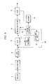
- FIG. 5 is a schematic diagram depicting an exhaust-gas treatment apparatus according to a third embodiment of the present invention.
- FIG. 6 is a schematic diagram depicting an exhaust-gas treatment apparatus according to a fourth embodiment of the present invention.
- FIG. 7 is a schematic diagram depicting an exhaust-gas treatment apparatus according to a fifth embodiment of the present invention.
- FIG. 8 is a schematic diagram depicting an exhaust-gas treatment apparatus according to a sixth embodiment of the present invention.
- FIG. 1 shows an exhaust-gas treatment apparatus according to this embodiment.
- the exhaust-gas treatment apparatus is disposed in a chimney flue downstream of a boiler 3 provided with a combustion furnace and includes a denitration apparatus 7 ; an air heater 9 ; a dry electrostatic precipitator (D-EP) 11 ; a desulfurization apparatus 13 based on the lime-gypsum method; and a wet electrical dust precipitator (W-EP) 15 .
- a denitration apparatus 7 includes a denitration apparatus 7 ; an air heater 9 ; a dry electrostatic precipitator (D-EP) 11 ; a desulfurization apparatus 13 based on the lime-gypsum method; and a wet electrical dust precipitator (W-EP) 15 .
- D-EP dry electrostatic precipitator
- W-EP wet electrical dust precipitator
- the boiler 3 is, for example, an oil-fired boiler for combusting heavy oil containing at least 0.5 wt % sulfur content.
- the denitration apparatus 7 removes nitrogen oxides (NOx) contained in the combustion exhaust gas from the boiler 3 .
- the air heater 9 performs heat exchange between combustion air supplied to the boiler 3 and combustion exhaust gas. Because of this, the combustion air is heated by the sensible heat of the combustion exhaust gas and supplied to the boiler 3 .
- the dry electrostatic precipitator 11 electrically captures dust in the combustion exhaust gas.
- the dust collected by the dry electrostatic precipitator 11 is processed by an ash treatment apparatus (dust treatment apparatus) 17 .
- the desulfurization apparatus 13 mainly removes SO 2 in the combustion exhaust gas by the lime-gypsum method.
- the desulfurizing effluent from the desulfurization apparatus 13 is introduced to a gypsum separator 29 , where gypsum 16 is separated.
- the desulfurizing effluent flowing out of the gypsum separator 29 is sprayed upstream of the desulfurization apparatus 13 as desulfurizing effluent containing dissolved salt 19 . More specifically, some of the desulfurizing effluent is sprayed by a two-fluid nozzle (refer to reference numeral 35 in FIG.
- the two-fluid nozzle changes liquid into very fine particles by means of pressurized air, and the sprayed desulfurizing effluent is preferably 10 ⁇ m to 100 ⁇ m, more preferably 20 to 50 ⁇ m, and still more preferably 25 to 35 ⁇ m in diameter.
- the environment is preferably at the water evaporating temperature or higher.
- the temperature is preferably equal to or higher than the SO 3 dew-point temperature at which a reaction with dissolved salt occurs. This is because, at a temperature below the dew point, the SO 3 gas is transformed into SO 3 mist and it becomes difficult to adhere to very fine particles of dry dissolved salt, thus decreasing the removal capability. For this reason, the exit temperature of the two-fluid nozzle is 130° C. or higher, and preferably 140° C. or higher.
- a residue of desulfurizing effluent that has not been sprayed upstream of the desulfurization apparatus 13 is processed by an effluent treatment apparatus 20 and then discharged outside.
- the wet electrical dust precipitator 15 removes dust and SO 3 .
- An NaOH aqueous solution for neutralization is supplied to the wet electrical dust precipitator 15 , as described below, and neutralized effluent merges with the desulfurizing effluent from the desulfurization apparatus 13 .
- a dielectric gas cleaning apparatus that dielectrically polarizes dielectric particles, such as sprayed water, capture precharged dust or SO 3 by the Coulomb force acting among the dielectric particles may be used as the wet electrical dust precipitator 15 .
- FIG. 2 shows the structure downstream of the dry electrostatic precipitator 11 shown in FIG. 1 . More specifically, the figure depicts the desulfurization apparatus 13 and the wet electrical dust precipitator 15 .
- the desulfurization apparatus 13 includes an absorbent spray 21 that sprays an absorbent containing CaCO 3 , a reaction layer 22 disposed below the absorbent spray 21 , and a reservoir 24 disposed below the reaction layer 22 .
- a liquid-jet column, a spray tower, or a plastic packed bed may be used for the reaction layer 22 .
- An absorbent feed pump 26 is disposed between the absorbent spray 21 and the reservoir 24 , and the absorbent in the reservoir 24 is sucked by this absorbent feed pump 26 into the absorbent spray 21 and circulated.
- Limestone is supplied from a limestone feed section 25 to the reservoir 24 , so that absorbent slurry containing CaCO 3 is produced. Because limestone contains about 0.5 to 2 wt % Mg, Mg also dissolves as a result of the limestone being dissolved in the desulfurization apparatus and reacts with SO 2 in the gas, thereby producing a Mg dissolved salt. Desulfurizing effluent containing the produced MgSO 4 is introduced via an eductor pump 27 to the gypsum separator 29 , together with gypsum.
- CaSO 4 is also dissolved in some of the desulfurizing effluent (the solubility of CaSO 4 is 2000 mg/1).
- the gypsum in the form of solid content is separated from liquid in the gypsum separator 29 .
- the separated gypsum is discharged outside for reuse.
- the liquid separated by the gypsum separator 29 is introduced as desulfurizing effluent into a sedimentation tank 31 .
- Particulate solid content that has not been separated in the gypsum separator 29 is further separated in the sedimentation tank 31 .
- particulate solid content with high specific gravity is sedimented.
- the sedimented liquid containing the sedimented particulate solid content is taken out from below and is returned to the reservoir 24 .
- the supernatant liquor of the desulfurizing effluent that has been separated in the sedimentation tank 31 is taken out by a dissolved-salt spray pump 33 and is introduced to a two-fluid nozzle 35 .
- the rest of desulfurizing effluent is branched off, is processed by an effluent treatment apparatus 37 , and is then discharged outside.
- Desulfurizing effluent (dissolved salt) is sprayed from the two-fluid nozzle 35 to a dissolved-salt spray area 36 in the chimney flue extending substantially vertically.
- An antechamber 31 a of the sedimentation tank 31 is provided with a salt level sensor (salt-level measuring section) 50 so that the concentration of dissolved salt in the desulfurizing effluent to be supplied to the two-fluid nozzle 35 can be measured.
- a salt level sensor salt-level measuring section
- a densimeter or a conductivity meter may be used for the salt level sensor 50 .
- the antechamber 31 a of the sedimentation tank 31 is also provided with a dissolved-salt feed section (dissolved-salt-level adjusting section) 52 .
- Dissolved-salt producing materials serving as raw materials for producing dissolved salts, such as NaOH and Mg(OH) 2
- dissolved salts such as Na 2 SO 4 and MgSO 4 are supplied from the dissolved-salt feed section 52 .
- a washing-water tank 40 is disposed near the wet electrical dust precipitator 15 .
- NaOH is supplied to this washing-water tank 40 from an alkaline-water feed section 42 in order to prevent a pH decrease resulting from SO 2 and SO 3 being adsorbed and removed in the wet electrical dust precipitator 15 .
- the washing water, containing NaOH, pooled in the washing-water tank 40 is introduced by a washing-water feed pump 44 to the wet electrical dust precipitator 15 .
- the corrosion of components in the apparatus is prevented by supplying this washing water for neutralization to the wet electrical dust precipitator 15 .
- a dissolved salt (Na 2 SO 4 ) is generated as a result of NaOH in the washing water reacting with SO 2 and SO 3 in the combustion exhaust gas.
- Na 2 SO 4 in the form of dissolved salt is present in the effluent discharged to the washing-water tank 40 .
- the effluent pooled in the washing-water tank 40 is re-introduced by the washing-water feed pump 44 to the wet electrical dust precipitator 15 , some of the effluent is supplied to the reservoir 24 of the desulfurization apparatus 13 .
- the exhaust-gas treatment apparatus with the above-described structure is operated as follows. First, the operation during steady operation is described, followed by the operation during initial operation.
- combustion exhaust gas containing SO 2 is discharged to the downstream chimney flue. Some (a few percent) of the SO 2 is oxidized into SO 3 at high-temperature sections in the boiler 3 and the denitration apparatus 7 .
- the combustion exhaust gas that has passed through the denitration apparatus 7 gives up some of its sensible heat to combustion air through the air heater 9 . At this time, the temperature of combustion exhaust gas decreases to about 160 to 200° C.
- the combustion exhaust gas that has passed through the air heater 9 is introduced to the dry electrostatic precipitator 11 , and dust in the combustion exhaust gas is removed.
- the removed dust is processed by the ash treatment apparatus 17 and is discharged outside.
- the combustion exhaust gas that has passed through the dry electrostatic precipitator 11 is sprayed with desulfurizing effluent (dissolved salt) from the two-fluid nozzle 35 in the dissolved-salt spray area 36 (refer to FIG. 2 ) when flowing through the chimney flue before the desulfurization apparatus 13 .
- Most of the SO 3 is removed by desulfurizing effluent atomized by the two-fluid nozzle 35 .
- SO 3 is removed from the gas as a result of being adsorbed to and fixed with the atomized dry particles of dissolved salt.
- MgSO 4 in the desulfurizing effluent is based on the limestone supplied as a raw material to the desulfurization apparatus 13
- Na 2 SO 4 in the desulfurizing effluent is based on NaOH added as a raw material to washing water that is supplied to the wet electrical dust precipitator 15 .
- Reaction formulae in the process of removing SO 3 with particles of dissolved salts are shown below as one example. Because these reaction formulae vary depending on the amount of sprayed dissolved salts, the actual SO 3 -removal mechanism is not limited to these reaction formulae.
- Particles of dissolved salts (MgSO 4 and Na 2 SO 4 ) that have been dried as a result of being sprayed into the combustion gas are subjected to the reaction processes with SO 3 , specified in the formulae below, thereby producing (Mg) 1/2 HSO 4 .H 2 O(solid) and NaHSO 4 .H 2 O(solid).
- Combustion exhaust gas from which most SO 3 has been removed with dissolved salts supplied from the two-fluid nozzle 35 is introduced to the desulfurization apparatus 13 .
- NaHSO 4 ⁇ H 2 O) that have been sprayed from the two-fluid nozzle 35 to adsorb SO 3 are also introduced to the reservoir 24 together with the absorbent.
- solid dissolved salts are reproduced via the following reaction processes. 2(Mg) 112 HSO 4 ⁇ H 2 O(solid)+CaCO 3 ⁇ MgSO 4 (dissolved)+CaSO 4 ⁇ 2H 2 O+CO 2 +H 2 O 2NaHSO 4 ⁇ H 2 O(solid)+CaCO 3 ⁇ Na 2 SO 4 (dissolved)+CaSO 4 ⁇ 2H 2 O+CO 2 +H 2 O
- the reproduced dissolved salts (MgSO 4 and Na 2 SO 4 ) are introduced to the two-fluid nozzle 35 again and used to remove SO 3 .
- the dissolved salts in the desulfurizing effluent are made to circulate from the reservoir 24 to the gypsum separator 29 , the sedimentation tank 31 , the two-fluid nozzle 35 , and the reservoir 24 in that order as described above, the dissolved salts in the desulfurizing effluent are conserved, thereby eliminating the need for extra operating costs.
- the concentration of dissolved salt can be increased by adjusting limestone supplied from the limestone feed section 25 and the flow rate of effluent discharged to the effluent treatment facility 37 .
- Desulfurizing effluent (dissolved salt) supplied from the two-fluid nozzle 35 has a concentration appropriate for adsorbing SO 3 according to various conditions. For this reason, the concentration of dissolved salt in the desulfurizing effluent supplied from the two-fluid nozzle 35 is controlled while the concentration of dissolved salt is being monitored with the salt level sensor 50 . More specifically, the flow rate of desulfurizing effluent that is sent to the effluent treatment apparatus 37 for disposal is adjusted. For example, if the concentration of dissolved salt is low, the rate of flow into the effluent treatment apparatus 37 is decreased to increase the concentration of dissolved salt. In contrast, if the concentration of dissolved salt is high, the rate of flow into the effluent treatment apparatus 37 is increased and salt in the circulating desulfurizing effluent is discarded to decrease the concentration of dissolved salt.
- the concentration of dissolved salt in the desulfurizing effluent is preferably controlled to range from 30000 mg/l to 100000 mg/l.
- Combustion exhaust gas from which SO 2 has been removed in the desulfurization apparatus 13 is introduced into the wet electrical dust precipitator 15 , where remaining dust, SO 3 , and so forth are removed from the combustion exhaust gas, which is then discharged outside via a chimney (not shown in the figure).
- the desired concentration of dissolved salt may not be obtained during initial operation because of insufficient circulation of dissolved salt. If this is the case, the desired concentration of dissolved salt is achieved from the early stage by supplying dissolved-salt producing materials and dissolved salt from the dissolved-salt feed section 52 . Once the concentration of dissolved salt is increased, it is not necessary to further supply dissolved-salt producing materials or dissolved salt because dissolved salt is circulated and conserved as described above.
- the exhaust-gas treatment apparatus can be constructed easily without having to provide a separate apparatus for producing dissolved salt.
- a membrane separation apparatus 54 may be provided downstream of the sedimentation tank 31 to further remove solid content in the desulfurizing effluent.
- reference symbol 56 denotes a tank that is disposed downstream of the membrane separation apparatus 54 to pool membrane-separated desulfurizing effluent (dissolved salt)
- reference symbol 33 a denotes a pump for supplying supernatant liquor in the sedimentation tank 31 to the membrane separation apparatus
- reference symbol 33 b denotes a pump for supplying desulfurizing effluent pooled in the tank 56 to the two-fluid nozzle 35 .
- a second embodiment according to the present invention will be described with reference to FIG. 4 .
- This embodiment differs from the first embodiment in that desulfurizing effluent is subjected to a non-effluent treatment.
- the other components are the same as those in the first embodiment. Therefore, the same components as those in the first embodiment are denoted with the same reference numerals, and hence, a description thereof will be omitted.
- a residue of desulfurizing effluent excluding the desulfurizing effluent that is supplied from the desulfurization apparatus 13 and introduced into the two-fluid nozzle 35 (refer to FIG. 2 ), is sprayed upstream of the dry electrostatic precipitator 11 via a flow channel 60 .
- the moisture content of the desulfurizing effluent that has been sprayed upstream of the dry electrostatic precipitator 11 is evaporated by sensible heat of the combustion exhaust gas flowing through the chimney flue, and consequently, dry and solid content is produced as a residue. This dry, solid content is then removed by the dry electrostatic precipitator 11 .
- a third embodiment according to the present invention will be described with reference to FIG. 5 .
- This embodiment differs from the first embodiment in that a heat exchanger for heat exchange of combustion exhaust gas is added.
- the other components are the same as those in the first embodiment. Therefore, the same components as those in the first embodiment are denoted with the same reference numerals, and hence, a description thereof will be omitted.
- This embodiment is also applicable to the second embodiment.
- a heat exchanger (gas-gas heater (GGH)) 62 that performs heat exchange between the combustion exhaust gas from the dry electrostatic precipitator 11 to the desulfurization apparatus 13 and the combustion exhaust gas before being released to the atmosphere downstream of the wet electrical dust precipitator 15 is provided.
- GGH gas-gas heater
- the heat exchanger 62 is indicated at two locations in the figure, it does not mean that two separate heat exchangers 62 are provided; it just means that heat exchange is performed between these heat exchangers 62 .
- White smoke can be prevented from occurring by increasing, with the heat exchanger 62 described above, the temperature of combustion exhaust gas before it is released to the atmosphere.
- heat may be extracted by the heat exchanger from the combustion exhaust gas upstream of the desulfurization apparatus 13 so that the extracted heat can be supplied to, for example, boiler feedwater for effective utilization of the heat.
- a fourth embodiment according to the present invention will be described with reference to FIG. 6 .
- This embodiment differs from the first embodiment in that, unlike the first embodiment, SO 3 removal is not performed by means of desulfurizing effluent.
- the boiler 3 , the denitration apparatus 7 , the air heater 9 , the dry electrostatic precipitator 11 , the desulfurization apparatus 13 , the wet electrical dust precipitator 15 , and the ash treatment apparatus 17 are the same as their counterparts in the first embodiment, and hence descriptions thereof will be omitted.
- An alkaline aqueous solution is supplied to the ash-dissolving section 70 from an alkaline-aqueous-solution feed section 72 for neutralizing ash.
- an alkaline aqueous solution an NaOH aqueous solution, Mg(OH) 2 , and so forth can be used.
- Effluent resulting after ash has been dissolved and neutralized in the ash-dissolving section 70 is sprayed as dissolved salt 74 towards the upstream end of the dry electrostatic precipitator 11 , namely, the combustion exhaust gas in the chimney flue between the air heater 9 and the dry electrostatic precipitator 11 .
- the feature that the two-fluid nozzle 35 (refer to FIG. 2 ) is used when the dissolved salt 74 is to be sprayed is the same as in the first embodiment.
- the reaction process of removing SO 3 in the combustion exhaust gas is the same as in the first embodiment because the dissolved salts in effluent use Na and Mg as their raw materials in the first embodiment. More specifically, when effluent containing dissolved salt is sprayed, the effluent is transformed into atomized droplets, and then the moisture content about the dissolved salt of these atomized droplets is evaporated with combustion exhaust gas. Because dried particles of dissolved salt are produced by evaporating the moisture content of the atomized droplets as described above, atomized particles of dissolved salt can be obtained. Then, as a result of SO 3 coming into contact with the atomized and dried particles of dissolved salt, contaminants are adsorbed and fixed, and thus removed from the gas.
- the dissolved salt in the effluent is dried by sensible heat of the combustion exhaust gas into solid dissolved salt, which adsorbs SO 3 and is captured by the dry electrostatic precipitator 11 .
- the solid dissolved salt captured by the dry electrostatic precipitator 11 is introduced to the ash-dissolving section 70 together with dust, is processed, and is sprayed again. Because dissolved salt is circulated in this manner, the concentration of dissolved salt in the effluent can be increased. This means that a concentration of dissolved salt appropriate for SO 3 removal can be achieved.
- the concentration of dissolved salt in the effluent to be sprayed into combustion exhaust gas can be adjusted easily by adjusting the concentration of an alkaline aqueous solution supplied from the alkaline-aqueous-solution feed section 72 .
- the present invention is not limited to this.
- a desulfurization apparatus based on the caustic soda method or the water magnesite method is also possible.
- a fifth embodiment according to the present invention will be described with reference to FIG. 7 .
- This embodiment differs from the fourth embodiment in that desulfurizing effluent from the desulfurization apparatus 13 is delivered to the ash-dissolving section 70 . Because the other components are the same, the same components are denoted with the same reference numerals, and hence a description thereof will be omitted.
- the concentration of dissolved salt in the effluent to be sprayed into combustion exhaust gas can be increased.
- FIG. 8 A sixth embodiment according to the present invention will be described with reference to FIG. 8 .
- This embodiment differs from the fifth embodiment in that the ash treatment apparatus 17 is omitted. Because the other components are the same, the same components are denoted with the same reference numerals, and hence a description thereof will be omitted.
- the ash treatment apparatus 17 (refer to FIG. 7 ) is not provided in this embodiment. Dust captured by the dry electrostatic precipitator 11 is supplied from the ash-dissolving section 70 via a flow channel 77 to the gypsum separator 29 , together with gypsum slurry from the desulfurization apparatus 13 . By doing so, dust is processed together with gypsum in the desulfurizing effluent (refer to reference numeral 18 ).
Abstract
Description
- 11: dry electrostatic precipitator
- 13: desulfurization apparatus
- 15: wet electrical dust precipitator
- 31: sedimentation tank
- 35: two-fluid nozzle (spray section)
- 54: membrane separation apparatus
MgSO4(dissolved)+SO3+3H2O→2(Mg)1/2HSO4.H2O(solid)
Na2SO4(dissolved)+SO3+3H2O→2NaHSO4H2O(solid)
2(Mg)112HSO4·H2O(solid)+CaCO3 →MgSO4(dissolved)+CaSO4·2H2O+CO2+H2O
2NaHSO4·H2O(solid)+CaCO3 →Na2SO4(dissolved)+CaSO4·2H2O+CO2+H2O
Claims (1)
Applications Claiming Priority (3)
| Application Number | Priority Date | Filing Date | Title |
|---|---|---|---|
| JP2007092512A JP5384799B2 (en) | 2007-03-30 | 2007-03-30 | Exhaust gas treatment apparatus and exhaust gas treatment method |
| JP2007-092512 | 2007-03-30 | ||
| PCT/JP2008/056300 WO2008123489A1 (en) | 2007-03-30 | 2008-03-31 | Exhaust gas treating apparatus and method of treating exhaust gas |
Publications (2)
| Publication Number | Publication Date |
|---|---|
| US20100119428A1 US20100119428A1 (en) | 2010-05-13 |
| US9155993B2 true US9155993B2 (en) | 2015-10-13 |
Family
ID=39830967
Family Applications (2)
| Application Number | Title | Priority Date | Filing Date |
|---|---|---|---|
| US12/593,300 Active US9155993B2 (en) | 2007-03-30 | 2008-03-31 | Exhaust-gas treatment apparatus and exhaust-gas treatment method |
| US12/872,370 Abandoned US20100329957A1 (en) | 2007-03-30 | 2010-08-31 | Exhaust-gas treatment apparatus and exhaust-gas treatment method |
Family Applications After (1)
| Application Number | Title | Priority Date | Filing Date |
|---|---|---|---|
| US12/872,370 Abandoned US20100329957A1 (en) | 2007-03-30 | 2010-08-31 | Exhaust-gas treatment apparatus and exhaust-gas treatment method |
Country Status (3)
| Country | Link |
|---|---|
| US (2) | US9155993B2 (en) |
| JP (1) | JP5384799B2 (en) |
| WO (1) | WO2008123489A1 (en) |
Cited By (1)
| Publication number | Priority date | Publication date | Assignee | Title |
|---|---|---|---|---|
| US20150182974A1 (en) * | 2013-12-30 | 2015-07-02 | Shanghai Clyde Bergemann Machinery Co., Ltd. | Flue gas treatment device |
Families Citing this family (20)
| Publication number | Priority date | Publication date | Assignee | Title |
|---|---|---|---|---|
| AU2011259877B2 (en) | 2010-05-31 | 2014-09-18 | Mitsubishi Heavy Industries, Ltd. | Exhaust gas treatment system and method |
| EP2578295B1 (en) | 2010-05-31 | 2020-05-27 | Mitsubishi Heavy Industries Engineering, Ltd. | Exhaust gas treatment system and method |
| WO2011152549A1 (en) | 2010-05-31 | 2011-12-08 | 三菱重工業株式会社 | Exhaust gas treatment system and method |
| AU2011259879B2 (en) | 2010-05-31 | 2014-08-28 | Mitsubishi Heavy Industries, Ltd. | Exhaust gas treatment system and method |
| CA2800997C (en) * | 2010-05-31 | 2015-12-22 | Mitsubishi Heavy Industries, Ltd. | Air pollution control system and method |
| AU2011259878B2 (en) * | 2010-05-31 | 2015-01-15 | Mitsubishi Heavy Industries, Ltd. | Exhaust gas processing system and method |
| JP5335740B2 (en) * | 2010-08-03 | 2013-11-06 | 株式会社日立製作所 | Exhaust gas treatment method and equipment |
| US8790444B2 (en) | 2011-03-01 | 2014-07-29 | Rsr Technologies, Inc. | Wet electrostatic precipitator and related methods |
| US8715402B2 (en) * | 2011-03-22 | 2014-05-06 | Mitsubishi Heavy Industries, Ltd. | Air pollution control system and air pollution control method, spray drying device of dewatering filtration fluid from desulfurization discharged water, and method thereof |
| JP2012200657A (en) * | 2011-03-24 | 2012-10-22 | Mitsubishi Heavy Ind Ltd | Spray-drying device for dehydrated filtrate from desulfurization wastewater, exhaust gas treatment system and method |
| JP5835940B2 (en) * | 2011-05-12 | 2015-12-24 | 三菱重工メカトロシステムズ株式会社 | Exhaust gas treatment method and exhaust gas treatment apparatus |
| JP5773756B2 (en) | 2011-05-31 | 2015-09-02 | 三菱日立パワーシステムズ株式会社 | Spray drying apparatus and exhaust gas treatment system for dehydrated filtrate |
| CN102604685B (en) * | 2011-12-29 | 2014-11-26 | 武汉凯迪工程技术研究总院有限公司 | Biomass synthesis gas positive pressure purification process and system configuration for oil production |
| CN102588050A (en) * | 2012-02-23 | 2012-07-18 | 庄建中 | Automobile exhaust purifier |
| CN103480260B (en) * | 2013-09-17 | 2015-07-01 | 上海大学 | Wet flue gas desulphurization technology by utilization of ethylene waste lye |
| JP2017136554A (en) * | 2016-02-04 | 2017-08-10 | 株式会社ユウ・ピー・アイ | Measuring-recording device for scrubber |
| CN108006683A (en) * | 2017-12-28 | 2018-05-08 | 华电郑州机械设计研究院有限公司 | A kind of method and apparatus that desulfurization wastewater zero-emission is realized using full flue gas |
| CN109173655A (en) * | 2018-10-31 | 2019-01-11 | 山东师范大学 | A kind of SCR denitration process of sintering flue gas |
| CN110252059B (en) * | 2019-06-14 | 2021-08-27 | 苏州市协力环保设备有限公司 | Fiberboard drying waste gas treatment system and fiberboard drying waste gas treatment process |
| BE1030226B1 (en) * | 2022-01-26 | 2023-08-29 | Indaver Nv | DEVICE FOR CLEANING OF FLUE GAS FROM THE BURNING OF SOLID COMBUSTIBLE MATERIAL AND OBTAINED CLEANED FLUE GAS |
Citations (38)
| Publication number | Priority date | Publication date | Assignee | Title |
|---|---|---|---|---|
| US3904742A (en) * | 1972-03-18 | 1975-09-09 | Ken Akimoto | Method for directly preparing a sulfate or sulfates from exhaust gases containing SO{HD 2 {B gas |
| US4539190A (en) * | 1984-09-11 | 1985-09-03 | Mitsubishi Jukogyo Kabushiki Kaisha | Method for the treatment of exhaust gases |
| US4643813A (en) * | 1984-12-13 | 1987-02-17 | Nippon Mining Co., Ltd. | Process for producing alkanesulfonic acids |
| US4649034A (en) | 1985-06-14 | 1987-03-10 | Conoco Inc. | Catalyzed flue gas desulfurization |
| US4687649A (en) * | 1983-09-09 | 1987-08-18 | Babcock-Hitachi Kabushiki Kaisha | Flue gas desulfurization process |
| JPS62197130A (en) | 1986-02-24 | 1987-08-31 | Kansai Electric Power Co Inc:The | Method for treating exhaust gas |
| US4915920A (en) | 1987-12-09 | 1990-04-10 | Yoshio Kobayashi | Dry method of purifying flue gas |
| JPH0557141A (en) | 1991-09-03 | 1993-03-09 | Ishikawajima Harima Heavy Ind Co Ltd | Flue gas desulfurization apparatus |
| US5270015A (en) * | 1986-11-07 | 1993-12-14 | Board Of Regents, The University Of Texas System | Apparatus for removing sulfur from sulfur containing gases |
| JPH0780244A (en) | 1993-09-14 | 1995-03-28 | Sumitomo Heavy Ind Ltd | Treatment of exhaust gas |
| JPH07110109A (en) | 1993-10-13 | 1995-04-25 | Mitsubishi Heavy Ind Ltd | Dry type simplified desulfurizer |
| JPH07155537A (en) | 1993-12-08 | 1995-06-20 | Kansai Electric Power Co Inc:The | High performance waste gas treating method and device therefor |
| US5599508A (en) * | 1993-06-01 | 1997-02-04 | The Babcock & Wilcox Company | Flue gas conditioning for the removal of acid gases, air toxics and trace metals |
| US5601791A (en) | 1994-12-06 | 1997-02-11 | The United States Of America As Represented By The Administrator Of The U.S. Environmental Protection Agency | Electrostatic precipitator for collection of multiple pollutants |
| JPH09141126A (en) * | 1995-11-20 | 1997-06-03 | Mitsubishi Heavy Ind Ltd | Duct type wet electric dust precipitator |
| US5820831A (en) * | 1994-06-09 | 1998-10-13 | Abb Environmental Systems, Div. Of Abb Flakt, Inc. | Method and apparatus for preparing calcium carbonate for scrubbing sulfur oxides from combustion effluents |
| JPH1176751A (en) | 1997-09-08 | 1999-03-23 | Mitsubishi Heavy Ind Ltd | Exhaust gas treating equipment |
| JP2000271434A (en) | 1999-03-25 | 2000-10-03 | Ishikawajima Harima Heavy Ind Co Ltd | Method and device for treating waste water of flue gas desulfurization plant |
| US6129910A (en) | 1993-06-02 | 2000-10-10 | Geltex Pharmaceuticals, Inc. | Water-insoluble noncrosslinked bile acid sequestrants |
| US6149713A (en) * | 1997-12-22 | 2000-11-21 | Mitsubishi Heavy Industries, Ltd. | Flue gas treating process |
| JP2001062247A (en) | 1999-06-22 | 2001-03-13 | Mitsubishi Heavy Ind Ltd | Method and system for desulfurizing exhaust gas |
| US6203598B1 (en) * | 1998-02-23 | 2001-03-20 | Mitsubishi Heavy Industries, Ltd. | Flue gas treating process and system |
| US6203508B1 (en) | 1997-10-16 | 2001-03-20 | Scimed Life Systems, Inc. | Thermal and stress mapping of body lumens |
| JP2001145818A (en) | 1999-11-24 | 2001-05-29 | Ishikawajima Harima Heavy Ind Co Ltd | Flue gas desulfurization method and device therefor |
| JP2001205044A (en) | 2000-01-21 | 2001-07-31 | Ishikawajima Harima Heavy Ind Co Ltd | Method for desulfurization waste water treatment and its equipment |
| EP1142625A1 (en) * | 1995-03-30 | 2001-10-10 | Mitsubishi Jukogyo Kabushiki Kaisha | Combustion exhaust gas treatment apparatus and method |
| US6594553B1 (en) * | 2000-04-18 | 2003-07-15 | Alstom (Switzerland) Ltd | Process for enhancing the sulfur capture capability of an alkaline earth material |
| US20040109807A1 (en) | 2002-12-10 | 2004-06-10 | Chemical Lime Company | Method of removing SO3 from flue gases |
| US20040109802A1 (en) | 2002-12-05 | 2004-06-10 | Meserole Frank B | Process for removing SO3/H2SO4 from flue gases |
| US20040120874A1 (en) * | 2002-12-02 | 2004-06-24 | Bert Zauderer | Reduction of sulfur, nitrogen oxides and volatile trace metals from combustion in furnaces and boilers |
| US20040208809A1 (en) | 2002-12-10 | 2004-10-21 | D Alesandro Raymond J | Method of removing SO3 from flue gases |
| US6863875B1 (en) * | 1998-04-13 | 2005-03-08 | Mitsubishi Heavy Industries, Ltd. | Flue gas treating system and process |
| US20050066772A1 (en) | 2003-09-26 | 2005-03-31 | Flores-Morales Jose Ignacio | Desulphurization of ferrous materials using glass cullet |
| US20050201914A1 (en) | 2004-03-12 | 2005-09-15 | American Electric Power Company, Inc. | System and method for treating a flue gas stream |
| US20050271569A1 (en) * | 2002-09-24 | 2005-12-08 | Kvaerner Power Oy | Method and an apparatus for processing flue gas scrubber material flows |
| US20060239881A1 (en) * | 2005-04-26 | 2006-10-26 | Mitsubishi Heavy Industries, Ltd. | Exhaust gas treatment system and exhaust gas treatment method |
| US20070231230A1 (en) | 2006-04-03 | 2007-10-04 | Codan Development, Llc | Process for removing so3/h2so4 from flue gases |
| US7524470B2 (en) * | 2006-07-13 | 2009-04-28 | Alstom Technology Ltd | Reduced liquid discharge in wet flue gas desulfurization |
-
2007
- 2007-03-30 JP JP2007092512A patent/JP5384799B2/en active Active
-
2008
- 2008-03-31 WO PCT/JP2008/056300 patent/WO2008123489A1/en active Application Filing
- 2008-03-31 US US12/593,300 patent/US9155993B2/en active Active
-
2010
- 2010-08-31 US US12/872,370 patent/US20100329957A1/en not_active Abandoned
Patent Citations (41)
| Publication number | Priority date | Publication date | Assignee | Title |
|---|---|---|---|---|
| US3904742A (en) * | 1972-03-18 | 1975-09-09 | Ken Akimoto | Method for directly preparing a sulfate or sulfates from exhaust gases containing SO{HD 2 {B gas |
| US4687649A (en) * | 1983-09-09 | 1987-08-18 | Babcock-Hitachi Kabushiki Kaisha | Flue gas desulfurization process |
| US4539190A (en) * | 1984-09-11 | 1985-09-03 | Mitsubishi Jukogyo Kabushiki Kaisha | Method for the treatment of exhaust gases |
| US4643813A (en) * | 1984-12-13 | 1987-02-17 | Nippon Mining Co., Ltd. | Process for producing alkanesulfonic acids |
| US4649034A (en) | 1985-06-14 | 1987-03-10 | Conoco Inc. | Catalyzed flue gas desulfurization |
| JPS62197130A (en) | 1986-02-24 | 1987-08-31 | Kansai Electric Power Co Inc:The | Method for treating exhaust gas |
| US4853194A (en) | 1986-02-24 | 1989-08-01 | Mitsubishi Jukogyo Kabushiki Kaisha | Method for treating exhaust gas |
| US5270015A (en) * | 1986-11-07 | 1993-12-14 | Board Of Regents, The University Of Texas System | Apparatus for removing sulfur from sulfur containing gases |
| US4915920A (en) | 1987-12-09 | 1990-04-10 | Yoshio Kobayashi | Dry method of purifying flue gas |
| JPH0557141A (en) | 1991-09-03 | 1993-03-09 | Ishikawajima Harima Heavy Ind Co Ltd | Flue gas desulfurization apparatus |
| US5599508A (en) * | 1993-06-01 | 1997-02-04 | The Babcock & Wilcox Company | Flue gas conditioning for the removal of acid gases, air toxics and trace metals |
| US6129910A (en) | 1993-06-02 | 2000-10-10 | Geltex Pharmaceuticals, Inc. | Water-insoluble noncrosslinked bile acid sequestrants |
| JPH0780244A (en) | 1993-09-14 | 1995-03-28 | Sumitomo Heavy Ind Ltd | Treatment of exhaust gas |
| JPH07110109A (en) | 1993-10-13 | 1995-04-25 | Mitsubishi Heavy Ind Ltd | Dry type simplified desulfurizer |
| JPH07155537A (en) | 1993-12-08 | 1995-06-20 | Kansai Electric Power Co Inc:The | High performance waste gas treating method and device therefor |
| US5820831A (en) * | 1994-06-09 | 1998-10-13 | Abb Environmental Systems, Div. Of Abb Flakt, Inc. | Method and apparatus for preparing calcium carbonate for scrubbing sulfur oxides from combustion effluents |
| US5601791A (en) | 1994-12-06 | 1997-02-11 | The United States Of America As Represented By The Administrator Of The U.S. Environmental Protection Agency | Electrostatic precipitator for collection of multiple pollutants |
| EP1142625A1 (en) * | 1995-03-30 | 2001-10-10 | Mitsubishi Jukogyo Kabushiki Kaisha | Combustion exhaust gas treatment apparatus and method |
| JPH09141126A (en) * | 1995-11-20 | 1997-06-03 | Mitsubishi Heavy Ind Ltd | Duct type wet electric dust precipitator |
| JPH1176751A (en) | 1997-09-08 | 1999-03-23 | Mitsubishi Heavy Ind Ltd | Exhaust gas treating equipment |
| US6203508B1 (en) | 1997-10-16 | 2001-03-20 | Scimed Life Systems, Inc. | Thermal and stress mapping of body lumens |
| US6149713A (en) * | 1997-12-22 | 2000-11-21 | Mitsubishi Heavy Industries, Ltd. | Flue gas treating process |
| US6203598B1 (en) * | 1998-02-23 | 2001-03-20 | Mitsubishi Heavy Industries, Ltd. | Flue gas treating process and system |
| US6863875B1 (en) * | 1998-04-13 | 2005-03-08 | Mitsubishi Heavy Industries, Ltd. | Flue gas treating system and process |
| JP2000271434A (en) | 1999-03-25 | 2000-10-03 | Ishikawajima Harima Heavy Ind Co Ltd | Method and device for treating waste water of flue gas desulfurization plant |
| JP2001062247A (en) | 1999-06-22 | 2001-03-13 | Mitsubishi Heavy Ind Ltd | Method and system for desulfurizing exhaust gas |
| JP2001145818A (en) | 1999-11-24 | 2001-05-29 | Ishikawajima Harima Heavy Ind Co Ltd | Flue gas desulfurization method and device therefor |
| JP2001205044A (en) | 2000-01-21 | 2001-07-31 | Ishikawajima Harima Heavy Ind Co Ltd | Method for desulfurization waste water treatment and its equipment |
| US6594553B1 (en) * | 2000-04-18 | 2003-07-15 | Alstom (Switzerland) Ltd | Process for enhancing the sulfur capture capability of an alkaline earth material |
| US20050271569A1 (en) * | 2002-09-24 | 2005-12-08 | Kvaerner Power Oy | Method and an apparatus for processing flue gas scrubber material flows |
| US20040120874A1 (en) * | 2002-12-02 | 2004-06-24 | Bert Zauderer | Reduction of sulfur, nitrogen oxides and volatile trace metals from combustion in furnaces and boilers |
| US6803025B2 (en) | 2002-12-05 | 2004-10-12 | Frank B. Meserole | Process for removing SO3/H2SO4 from flue gases |
| US20040109802A1 (en) | 2002-12-05 | 2004-06-10 | Meserole Frank B | Process for removing SO3/H2SO4 from flue gases |
| US20040208809A1 (en) | 2002-12-10 | 2004-10-21 | D Alesandro Raymond J | Method of removing SO3 from flue gases |
| US20040109807A1 (en) | 2002-12-10 | 2004-06-10 | Chemical Lime Company | Method of removing SO3 from flue gases |
| US20050066772A1 (en) | 2003-09-26 | 2005-03-31 | Flores-Morales Jose Ignacio | Desulphurization of ferrous materials using glass cullet |
| US20050201914A1 (en) | 2004-03-12 | 2005-09-15 | American Electric Power Company, Inc. | System and method for treating a flue gas stream |
| US20060239881A1 (en) * | 2005-04-26 | 2006-10-26 | Mitsubishi Heavy Industries, Ltd. | Exhaust gas treatment system and exhaust gas treatment method |
| JP2006326575A (en) | 2005-04-26 | 2006-12-07 | Mitsubishi Heavy Ind Ltd | Device and method of treating exhaust gas |
| US20070231230A1 (en) | 2006-04-03 | 2007-10-04 | Codan Development, Llc | Process for removing so3/h2so4 from flue gases |
| US7524470B2 (en) * | 2006-07-13 | 2009-04-28 | Alstom Technology Ltd | Reduced liquid discharge in wet flue gas desulfurization |
Non-Patent Citations (6)
| Title |
|---|
| A Decision to Grant a Patent dated Sep. 24, 2013 in corresponding to Japanese Application No. 2007-092512. |
| International Search Report of PCT/JP2008/056300, mailing date of Jun. 17, 2008. |
| Japanese Office Action dated Oct. 30, 2012, issued in corresponding Japanese Patent Application No. 2007-092512, w/ English Translation, (10 pages). |
| U.S. Office Action dated Feb. 13, 2013, issued in corresponding U.S. Appl. No. 12/872,370. |
| U.S. Office Action dated Feb. 4, 2011, issued in corresponding U.S. Appl. No. 12/872,370 (12 pages). |
| U.S. Office Action dated Sep. 8, 2011, issued in corresponding U.S. Appl. No. 12/872,370 (7 pages). |
Cited By (2)
| Publication number | Priority date | Publication date | Assignee | Title |
|---|---|---|---|---|
| US20150182974A1 (en) * | 2013-12-30 | 2015-07-02 | Shanghai Clyde Bergemann Machinery Co., Ltd. | Flue gas treatment device |
| US9782782B2 (en) * | 2013-12-30 | 2017-10-10 | Shanghai Clyde Bergemann Machinery Co., Ltd. | Flue gas treatment device |
Also Published As
| Publication number | Publication date |
|---|---|
| US20100119428A1 (en) | 2010-05-13 |
| US20100329957A1 (en) | 2010-12-30 |
| WO2008123489A1 (en) | 2008-10-16 |
| JP2008246406A (en) | 2008-10-16 |
| JP5384799B2 (en) | 2014-01-08 |
Similar Documents
| Publication | Publication Date | Title |
|---|---|---|
| US9155993B2 (en) | Exhaust-gas treatment apparatus and exhaust-gas treatment method | |
| JP4920993B2 (en) | Exhaust gas treatment apparatus and exhaust gas treatment method | |
| CA2782843C (en) | A method and a device for cleaning a carbon dioxide rich flue gas | |
| JP5984712B2 (en) | Exhaust gas treatment system and exhaust gas treatment method | |
| US8877152B2 (en) | Oxidation system and method for cleaning waste combustion flue gas | |
| JPWO2004023040A1 (en) | Smoke treatment system | |
| WO2014103682A1 (en) | Exhaust gas processing equipment and gas turbine power generation system using same | |
| JP5144967B2 (en) | Exhaust gas treatment system | |
| CN100475316C (en) | Exhaust gas treatment device and exhaust gas treatment method | |
| JPH1157397A (en) | Gas purifying method | |
| JPH078748A (en) | Wet process flue gas desulfurization and device using desulfurization method | |
| KR100266098B1 (en) | Method of treating combustion gas and apparatus therefor | |
| US10617999B2 (en) | Process for removing SO2 from flue gases using liquid sorbent injection | |
| JP2000053980A (en) | Purification of gas | |
| JPH11319479A (en) | Treatment of flue gas | |
| JP4023015B2 (en) | Method for removing unburned carbon from heavy oil combustion ash | |
| JP4507404B2 (en) | Boiler flue gas treatment system | |
| JPH1133349A (en) | Flue gas treatment method and flue gas treatment installation | |
| JP2012020216A (en) | Wet-type apparatus for desulfurizing flue gas | |
| MXPA99001738A (en) | Process and system to treat hum gas | |
| JP2003205222A (en) | Stack gas desulfurization apparatus | |
| MXPA98001386A (en) | Procedure and system to treat hum gas |
Legal Events
| Date | Code | Title | Description |
|---|---|---|---|
| AS | Assignment |
Owner name: MITSUBISHI HEAVY INDUSTRIES ENVIRONMENT ENGINEERIN Free format text: ASSIGNMENT OF ASSIGNORS INTEREST;ASSIGNORS:NAGAYASU, HIROMITSU;UEDA, YASUTOSHI;HAMAGUCHI, RYOKICHI;AND OTHERS;REEL/FRAME:023306/0578 Effective date: 20090528 |
|
| STCF | Information on status: patent grant |
Free format text: PATENTED CASE |
|
| AS | Assignment |
Owner name: MITSUBISHI HITACHI POWER SYSTEMS ENVIRONMENTAL SOL Free format text: ASSIGNMENT OF ASSIGNORS INTEREST;ASSIGNOR:MITSUBISHI HEAVY INDUSTRIES ENVIRONMENTAL & CHEMICAL ENGINEERING CO., LTD.;REEL/FRAME:038301/0702 Effective date: 20151001 |
|
| MAFP | Maintenance fee payment |
Free format text: PAYMENT OF MAINTENANCE FEE, 4TH YEAR, LARGE ENTITY (ORIGINAL EVENT CODE: M1551); ENTITY STATUS OF PATENT OWNER: LARGE ENTITY Year of fee payment: 4 |
|
| AS | Assignment |
Owner name: MITSUBISHI POWER ENVIRONMENTAL SOLUTIONS, LTD., JAPAN Free format text: CHANGE OF NAME;ASSIGNOR:MITSUBISHI HITACHI POWER SYSTEMS ENVIRONMENTAL SOLUTIONS, LTD.;REEL/FRAME:055055/0721 Effective date: 20200901 |
|
| MAFP | Maintenance fee payment |
Free format text: PAYMENT OF MAINTENANCE FEE, 8TH YEAR, LARGE ENTITY (ORIGINAL EVENT CODE: M1552); ENTITY STATUS OF PATENT OWNER: LARGE ENTITY Year of fee payment: 8 |