US9166322B2 - Female electric terminal with gap between terminal beams - Google Patents
Female electric terminal with gap between terminal beams Download PDFInfo
- Publication number
- US9166322B2 US9166322B2 US14/169,216 US201414169216A US9166322B2 US 9166322 B2 US9166322 B2 US 9166322B2 US 201414169216 A US201414169216 A US 201414169216A US 9166322 B2 US9166322 B2 US 9166322B2
- Authority
- US
- United States
- Prior art keywords
- beams
- clamp arms
- terminal
- terminal base
- clamp
- Prior art date
- Legal status (The legal status is an assumption and is not a legal conclusion. Google has not performed a legal analysis and makes no representation as to the accuracy of the status listed.)
- Active, expires
Links
Images

Classifications
-
- H—ELECTRICITY
- H01—ELECTRIC ELEMENTS
- H01R—ELECTRICALLY-CONDUCTIVE CONNECTIONS; STRUCTURAL ASSOCIATIONS OF A PLURALITY OF MUTUALLY-INSULATED ELECTRICAL CONNECTING ELEMENTS; COUPLING DEVICES; CURRENT COLLECTORS
- H01R13/00—Details of coupling devices of the kinds covered by groups H01R12/70 or H01R24/00 - H01R33/00
- H01R13/02—Contact members
- H01R13/10—Sockets for co-operation with pins or blades
- H01R13/11—Resilient sockets
- H01R13/113—Resilient sockets co-operating with pins or blades having a rectangular transverse section
-
- H—ELECTRICITY
- H01—ELECTRIC ELEMENTS
- H01R—ELECTRICALLY-CONDUCTIVE CONNECTIONS; STRUCTURAL ASSOCIATIONS OF A PLURALITY OF MUTUALLY-INSULATED ELECTRICAL CONNECTING ELEMENTS; COUPLING DEVICES; CURRENT COLLECTORS
- H01R13/00—Details of coupling devices of the kinds covered by groups H01R12/70 or H01R24/00 - H01R33/00
- H01R13/02—Contact members
- H01R13/15—Pins, blades or sockets having separate spring member for producing or increasing contact pressure
- H01R13/18—Pins, blades or sockets having separate spring member for producing or increasing contact pressure with the spring member surrounding the socket
-
- H—ELECTRICITY
- H01—ELECTRIC ELEMENTS
- H01R—ELECTRICALLY-CONDUCTIVE CONNECTIONS; STRUCTURAL ASSOCIATIONS OF A PLURALITY OF MUTUALLY-INSULATED ELECTRICAL CONNECTING ELEMENTS; COUPLING DEVICES; CURRENT COLLECTORS
- H01R2101/00—One pole
Definitions
- the present invention relates in general to an electrical terminal and, more specifically, to a female electrical terminal designed for controlling the force required to insert a corresponding male terminal.
- Electrical connectors may be used in automobiles, for example, in completing electrical circuits with components in a power distribution box or connecting a wiring harness to an electrical device.
- These connectors may include a female terminal and a corresponding male terminal.
- the female terminal includes opposed beams that are biased into engagement with the male blade.
- the female terminal is typically made from a material having desirable electrical conductivity, such as copper.
- the female terminal may include a spring feature that helps bias the beams into engagement with the blade in order to maintain strong contact between the female terminal and the male terminal. By biasing the beams into engagement with the blade, the amount of force required to insert the male blade between the beams is increased. It would be advantageous to have a female electrical terminal that allows greater control over the magnitude of the required insertion force while still maintaining strong contact between the female terminal and the male terminal.
- the female electric terminal assembly includes a body.
- a first beam extends from the body.
- a second beam extends from the body.
- a channel is defined between the first beam and the second beam.
- a clamp is attached to the body. The clamp applies a force to bias the first beam into the channel. The clamp applies a force to bias the second beam into the channel. A gap is maintained between the first beam and the second beam.
- the female electric terminal assembly includes a body.
- a first beam extends from the body to a first beam end.
- a second beam extends from the body to a second beam end.
- a clamp biases the first beam and the second beam in an inward direction into the channel.
- the first beam extends from the first beam end in the inward direction to a contact area.
- the contact area is the portion of the first beam that is closest to the second beam.
- the first beam extends from the contact area in an outward direction to the body. The first beam does not contact the second beam at the contact area.
- the female electric terminal assembly includes a terminal base.
- the terminal base is made of a first electrically-conductive material.
- the terminal base includes a body.
- a first beam extends from the body.
- a second beam extends from the body to define a channel between the first beam and the second beam.
- the first beam and the second beam extend from the body in an inward direction to respective contact areas.
- the first beam and the second beam extend from the contact areas in an outward direction that is opposite the inward direction to respective beam ends.
- a clamp is attached to the terminal base.
- the clamp made of a second electrically-conductive material that is a different material than the first electrically-conductive material. The clamp applies a force to bias the first beam into the channel.
- the clamp applies a force to bias the second beam into the channel.
- the first beam and the second beam are in respective rest positions relative to the body before the clamp is attached to the terminal base and the first beam and the second beam are separated by a rest width.
- the first beam and the second beam are in respective clamped positions relative to the body when the clamp is attached to the terminal base and are separated by a clamped width.
- the clamped width is less than the rest width. A gap is maintained between the first beam and the second beam.
- FIG. 1 is a perspective view of a female electric terminal assembly.
- FIG. 2 is a perspective view of the female electric terminal assembly and a corresponding male blade terminal with a wire attached to the female electric terminal assembly.
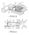
- FIG. 3 is a perspective view similar to FIG. 2 , showing the male blade terminal mated with the female electric terminal assembly.
- FIG. 4 is a cross-sectional view of a terminal base of the female electrical terminal assembly.
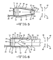
- FIG. 5 is a cross sectional view similar to FIG. 4 , taken along the line 5 - 5 of FIG. 3 .
- FIG. 6 is a cross-sectional view similar to FIG. 5 , showing the female electric terminal assembly engaged with the male blade terminal.
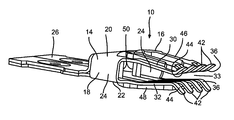
- FIG. 1 a female electric terminal assembly, indicated generally at 10 .
- the female electric terminal assembly 10 is configured to mate with a corresponding male blade terminal 12 , as shown in FIG. 3 , to create an electrical connection.
- the female electric terminal assembly 10 and the male blade terminal 12 may be enclosed in respective housings (not shown) and are suitable for use in situations in which it is desirable to have a separable electrical connection.
- the female electric terminal assembly 10 includes a terminal base 14 and a clamp 16 .
- the terminal base 14 is made of an electrically-conductive material, such as copper, or aluminum, but the terminal base 14 may be made of any other desired material.
- the illustrated terminal base 14 is made from a single piece of sheet metal stamped and folded into the illustrated shape. However, the terminal base 14 may be made from more than one piece of material and may be made by any desired method. Further, the particular shape of the terminal base 14 may be different from that illustrated, if desired.
- the terminal base 14 includes a body 18 .
- the body 18 has a generally rectangular box shape including a first side 20 and a spaced-apart second side 22 .
- the first side 20 and the second side 22 are connected by two side walls 24 .
- a termination area 26 extends from the body 18 .
- an electrically-conductive wire 28 is attached to the termination area 26 .
- the terminal base 14 also includes a plurality of first beams 30 that extend from the first side 20 of the body 18 and a plurality of second beams 32 that extend from the second side 22 of the body 18 .
- the first beams 30 and the second beams 32 define a channel 33 there between.
- the first beams 30 and the second beams 32 extend from the body 18 on opposed sides of a connection plane 34 (best seen in FIG. 4 , FIG. 5 , and FIG. 6 ).
- the connection plane 34 is located in the channel 33 and corresponds to the position of the male blade terminal 12 when the male blade terminal 12 is mated with the female electric terminal assembly 10 .
- the first beams 30 and the second beams 32 extend from the body 18 in opposed pairs, with one member of each pair on each side of the connection plane 34 . However, this is not necessary and the first beams 30 and the second beams 32 may have any other desired arrangement that allows them to mate with the corresponding male blade terminal 12 .
- Each of the first beams 30 and second beams 32 includes a contact area 36 .
- the first beams 30 and the second beams 32 extend from the body 18 , they extend in an inward direction 38 (see FIG. 4 , FIG. 5 , and FIG. 6 ) toward the connection plane 34 up to the contact area 36 .
- the first beams 30 and second beams 32 extend past the contact area 36 and extend in an outward direction 40 (see FIG. 4 , FIG. 5 , and FIG. 6 ) away from the connection plane 34 to respective beam ends 42 .
- the contact areas 36 are the portions of the first beams 30 and second beams 32 that are closest to the connection plane 34 .
- the contact area 36 of a particular first beam 30 is also the portion of that first beam 30 that is closest to the respective paired second beam 32 .
- the contact areas 36 are the portions of the first beams 30 and the second beams 32 that are in contact with the male blade terminal 12 when the male blade terminal 12 is mated with the female electric terminal assembly 10 , as shown in FIG. 3 and FIG. 6 .
- each of the outwardly-extending portions of the first beams 30 and the second beams 32 between the contact areas 36 and the beam ends 42 defines an initial engagement surface 44 .
- the initial engagement surface 44 is the portion of the respective first beam 30 or second beam 32 that the male blade terminal 12 first engages when the male blade terminal 12 is mated with the female electric terminal assembly 10 , as will be described below.
- the clamp 16 includes first clamp arms 46 on the first side 20 of the body 18 and second clamp arms 48 on the second side 22 of the body 18 .
- the first clamp arms 46 and the second clamp arms 48 are connected by lateral portions 50 that extend through the body 18 .
- the clamp 16 serves to bias the first beams 30 and the second beams 32 of the terminal base 14 in the inward direction 38 , as is described below.
- the specific shape of the clamp 16 shown is only one embodiment, and the clamp 16 may have a different shape from that shown, if desired.
- the clamp 16 is made of an electrically-conductive material, but may be made of any other desired material.
- the clamp 16 may be made of a different material than the terminal base 14 .
- the illustrated clamp 16 is made of stainless steel. However, the clamp 16 may be made of any other desired material.
- the illustrated clamp 16 is made from a single piece of sheet metal stamped and folded into the illustrated shape. However, the clamp 16 may be made from more than one piece of material and may be made by any desired method. Further, the particular shape of the clamp 16 may be different from that illustrated, if desired.
- the clamp 16 serves to bias the first beams 30 and the second beams 32 into engagement of the male blade terminal 12 .
- the first clamp arms 46 are disposed to engage the first beams 30 and bias the first beams 30 in the inward direction 38 toward the connection plane 34 .
- the second clamp arms 48 are disposed to engage the second beams 32 and bias the second beams 32 in the inward direction 38 toward the connection plane 34 .
- the design and operation of the clamp 16 is similar to the clamping member described in U.S. Pat. No. 7,892,050, the disclosure of which is incorporated herein by reference.
- the first beams 30 do not engage the second beams 32 , and a gap 56 is maintained between the first beams 30 and the second beams 32 of the terminal base 14 as shown in FIG. 5 .
- FIG. 4 a cross-section view of the terminal base 14 is shown without the clamp 16 attached.
- the first beams 30 and the second beams 32 are shown in respective rest positions relative to the body 18 . As shown, there is a rest space between the contact area 36 of the first beams 30 and the contact area 36 of the second beams 32 .
- the rest space has a rest width 52 .
- FIG. 5 a cross-sectional view similar to that of FIG. 4 is shown.
- the cross-sectional view shown in FIG. 5 is taken along line 5 - 5 of FIG. 3 .
- the clamp 16 biases the first beams 30 and the second beams 32 in the inward direction 38 toward the connection plane 34 . Therefore, the first beams 30 and the second beams 32 are pre-tensioned in the inward direction 38 by the clamp 16 .
- the first beams 30 and the second beams 32 are in respective clamped positions relative to the body 18 , and there is a clamped space between the contact area 36 of the first beams 30 and the contact area 36 of the second beams 32 .
- the clamped space has a clamped width 54 .
- the clamped width 54 is less than the rest width 52 .
- the first beams 30 are not in contact with the second beams 32 , and the gap 56 is maintained between the first beams 30 and the second beams 32 .
- the illustrated gap 56 extends the full length of the first beams 30 and the second beams 32 .
- FIG. 6 a cross-sectional view similar to that of FIG. 5 is shown, with the male blade terminal 12 mated with the female electric terminal assembly 10 .
- the initial engagement surfaces 44 are angled so that, from the beam ends 42 , the first beam 30 and the second beam 32 angle in the inward direction 38 toward each other to the contact area 36 .
- the first beam 30 does not contact the second beam 32 at the contact area 36 .
- the first beam 30 and the second beam 32 angle in the outward direction 40 away from each other.
- the engaged width 62 is at least equal to a width of the male blade terminal 12 . It should be appreciated that in the illustrated embodiment, the first blades 30 and the second blades 32 are arranged in opposed pairs on opposite sides of the connection plane 34 , and the engaged width 62 is equal to the width of the male blade terminal 12 . However, the first blades 30 and the second blades 32 may be arranged different, for example with the second blade opposite a space between the first blades, so that the distance between the first beams 30 and the second beams 32 is greater than the thickness of the male blade terminal 12 . In the illustrated embodiment, the engaged width 62 is greater than the rest width 52 , but the engaged width 62 may be equal to or less than the rest width 52 , if desired.
- the female electric terminal assembly 10 applies a normal force (Fn) on the male blade terminal 12 in the inward direction 38 .
- the components of the normal force (Fn) include a clamp force (Fc) applied by the clamp 16 and a base force (Fb) applied by the terminal base 14 .
- Fc clamp force
- Fb base force
- the first blades 30 and the second blades 32 are pre-tensioned in the inward direction 38 by the clamp 16 .
- a pre-tensioning force (Ft) is applied to the first blades 30 and the second blade 32 .
- the pre-tensioning force (Ft) is relieved when the first blades 30 and the second blades 32 are moved from the clamped positions (shown in FIG. 5 ) to the rest positions (shown in FIG. 4 ).
- the frictional force will also resist the male blade terminal 12 being removed from the female electric terminal assembly 10 .
- There may be a desired maximum value of the normal force in order to limit the amount of force necessary to mate the male blade terminal with the female electric terminal assembly 10 .
- the normal force helps maintain positive contact between the terminal base 14 and the male blade terminal 12 , and that contact is helpful in maintaining desired electrical conductivity between the two components.
- There may be a desired minimum value for the normal force in order to maintain sufficient contact between the terminal base 14 and the male blade terminal 12 .
- the design of the female electric terminal 10 allows the normal force to be selected based on factors including the spring characteristics of the terminal base 14 , the spring characteristics of the clamp 16 , and the relative size of the clamped width 54 and the engaged width 62 . It should be appreciated that because the female electric terminal assembly 10 includes the gap 56 , the first beams 30 and the second beams 32 do not have to travel as far to be moved from the clamped width 54 to the engaged width 62 , as compared to a conventional female terminal.
Abstract
Description
Fn=Fc+Fb−Ft
Claims (12)
Priority Applications (2)
| Application Number | Priority Date | Filing Date | Title |
|---|---|---|---|
| US14/169,216 US9166322B2 (en) | 2013-02-08 | 2014-01-31 | Female electric terminal with gap between terminal beams |
| DE201410001692 DE102014001692A1 (en) | 2013-02-08 | 2014-02-07 | Socket electrical connection subunit for completing electric circuits in energy distribution box, in motor car, has clamp attached at connector base, for applying force to pre-tension pins into channel for maintaining gap between pins |
Applications Claiming Priority (2)
| Application Number | Priority Date | Filing Date | Title |
|---|---|---|---|
| US201361762552P | 2013-02-08 | 2013-02-08 | |
| US14/169,216 US9166322B2 (en) | 2013-02-08 | 2014-01-31 | Female electric terminal with gap between terminal beams |
Publications (2)
| Publication Number | Publication Date |
|---|---|
| US20140227915A1 US20140227915A1 (en) | 2014-08-14 |
| US9166322B2 true US9166322B2 (en) | 2015-10-20 |
Family
ID=51297737
Family Applications (1)
| Application Number | Title | Priority Date | Filing Date |
|---|---|---|---|
| US14/169,216 Active 2034-03-17 US9166322B2 (en) | 2013-02-08 | 2014-01-31 | Female electric terminal with gap between terminal beams |
Country Status (2)
| Country | Link |
|---|---|
| US (1) | US9166322B2 (en) |
| CN (1) | CN104009312A (en) |
Cited By (9)
| Publication number | Priority date | Publication date | Assignee | Title |
|---|---|---|---|---|
| US20190237891A1 (en) * | 2017-01-31 | 2019-08-01 | Kostal Kontakt Systeme Gmbh | Contact Blade for a Socket-Like Connector Part, and Socket-Like Connector Part |
| US10693252B2 (en) | 2016-09-30 | 2020-06-23 | Riddell, Inc. | Electrical connector assembly for high-power applications |
| US10992073B1 (en) * | 2019-12-20 | 2021-04-27 | Lear Corporation | Electrical terminal assembly with increased contact area |
| US20210194171A1 (en) * | 2019-12-20 | 2021-06-24 | Lear Corporation | Electrical terminal assembly with connection retainer |
| US11398696B2 (en) | 2018-06-07 | 2022-07-26 | Eaton Intelligent Power Limited | Electrical connector assembly with internal spring component |
| US11411336B2 (en) | 2018-02-26 | 2022-08-09 | Eaton Intelligent Power Limited | Spring-actuated electrical connector for high-power applications |
| US11721942B2 (en) | 2019-09-09 | 2023-08-08 | Eaton Intelligent Power Limited | Connector system for a component in a power management system in a motor vehicle |
| US11721927B2 (en) | 2019-09-09 | 2023-08-08 | Royal Precision Products Llc | Connector recording system with readable and recordable indicia |
| US11929572B2 (en) | 2020-07-29 | 2024-03-12 | Eaton Intelligent Power Limited | Connector system including an interlock system |
Families Citing this family (16)
| Publication number | Priority date | Publication date | Assignee | Title |
|---|---|---|---|---|
| US9190756B2 (en) | 2013-08-01 | 2015-11-17 | Lear Corporation | Electrical terminal assembly |
| US9142902B2 (en) | 2013-08-01 | 2015-09-22 | Lear Corporation | Electrical terminal assembly |
| US9711926B2 (en) | 2013-11-19 | 2017-07-18 | Lear Corporation | Method of forming an interface for an electrical terminal |
| US9331448B2 (en) * | 2014-03-25 | 2016-05-03 | Tyco Electronics Corporation | Electrical connector having primary and secondary leadframes |
| DE102014217933A1 (en) | 2014-09-08 | 2016-03-10 | Continental Automotive Gmbh | Electric motor with SMD components and associated connection part |
| US9647368B2 (en) * | 2014-09-22 | 2017-05-09 | Ideal Industries, Inc. | Terminals for electrical connectors |
| CN104283034A (en) * | 2014-09-24 | 2015-01-14 | 沈阳兴华航空电器有限责任公司 | Novel jack contact body |
| CN104577361A (en) * | 2014-12-29 | 2015-04-29 | 温州市珠城电气有限公司 | Flag-shaped duckbilled terminal |
| EP3182525A1 (en) * | 2015-12-18 | 2017-06-21 | Delphi Technologies, Inc. | Contact terminal assembled from at least two parts |
| US10141669B2 (en) * | 2016-08-01 | 2018-11-27 | Te Connectivity Corporation | Plug connector having a tab terminal for a power connector system |
| DE102016221351A1 (en) * | 2016-10-28 | 2018-05-03 | Te Connectivity Germany Gmbh | Flat contact socket with extension arm |
| EP3442080A1 (en) * | 2017-08-09 | 2019-02-13 | HILTI Aktiengesellschaft | Plug connector for a battery unit |
| US10193247B1 (en) * | 2017-11-14 | 2019-01-29 | Lear Corporation | Electrical contact spring with extensions |
| JP7001961B2 (en) * | 2018-03-02 | 2022-01-20 | 株式会社オートネットワーク技術研究所 | Female terminal |
| US10826215B2 (en) * | 2018-09-25 | 2020-11-03 | Alltop Electronics (Suzhou) Ltd. | Electrical connector and electrical connector assembly with the same |
| US20230246369A1 (en) * | 2022-01-28 | 2023-08-03 | J.S.T. Corporation | Power connector system having a right-angle type plug connector or a straight type plug connector engageable with a header connector |
Citations (52)
| Publication number | Priority date | Publication date | Assignee | Title |
|---|---|---|---|---|
| US2774951A (en) | 1954-12-16 | 1956-12-18 | Aircraft Marine Prod Inc | Terminal clip |
| US2921287A (en) | 1957-01-18 | 1960-01-12 | Burndy Corp | Snap fit interlocking connector |
| US3550069A (en) | 1967-06-06 | 1970-12-22 | Amp Inc | Electrical connector tab receptacles |
| US4553799A (en) * | 1983-07-11 | 1985-11-19 | Deters Paul M | Electrical connector clip assembly |
| US4553808A (en) | 1983-12-23 | 1985-11-19 | Amp Incorporated | Electrical terminal intended for mating with a terminal tab |
| US4570147A (en) | 1980-04-28 | 1986-02-11 | Pacific Engineering Company, Ltd. | Time delay fuse |
| US4583812A (en) | 1984-06-29 | 1986-04-22 | Amp Incorporated | Electrical contact with assist spring |
| US4646052A (en) | 1985-12-24 | 1987-02-24 | Sumitomo Wiring System, Ltd. | Slow blow fuse |
| US4672352A (en) | 1986-04-23 | 1987-06-09 | Kabushiki Kaisha T An T | Fuse assembly |
| US4751490A (en) | 1986-04-18 | 1988-06-14 | Yazaki Corporation | Fuse terminal |
| US4842534A (en) | 1988-10-14 | 1989-06-27 | Interlock Corporation | Fuse/bus bar assembly |
| US4869972A (en) | 1987-04-06 | 1989-09-26 | Yazaki Corporation | Material for fuse |
| US4871990A (en) | 1987-08-25 | 1989-10-03 | Yazaki Corporation | Cartridge fuse |
| US4941851A (en) | 1989-08-15 | 1990-07-17 | Hsueh Fu Cheng | Fuse holder for flat-type fuse block |
| US4958426A (en) | 1987-09-01 | 1990-09-25 | Yazaki Corporation | Fuse terminal manufacturing method |
| US5007865A (en) * | 1987-09-28 | 1991-04-16 | Amp Incorporated | Electrical receptacle terminal |
| US5088940A (en) | 1989-10-24 | 1992-02-18 | Yazaki Corporation | Electrical junction device |
| US5147230A (en) | 1991-12-19 | 1992-09-15 | General Motors Corporation | Two piece electrical female terminal |
| US5226842A (en) | 1991-01-11 | 1993-07-13 | Yazaki Corporation | Female terminal |
| US5350321A (en) | 1992-01-28 | 1994-09-27 | Yazaki Corporation | Female terminal |
| US5416461A (en) | 1992-07-17 | 1995-05-16 | Yazaki Corporation | Fusible link |
| US5427552A (en) | 1993-11-22 | 1995-06-27 | Chrysler Corporation | Electrical terminal and method of fabricating same |
| US5474475A (en) | 1993-07-07 | 1995-12-12 | Sumitomo Wiring Systems, Ltd. | Construction for fixing bus bar for miniature fuses to electrical connection box |
| US5488346A (en) | 1993-06-21 | 1996-01-30 | Yazaki Corporation | Connection terminal for fuse |
| US5581225A (en) | 1995-04-20 | 1996-12-03 | Littelfuse, Inc. | One-piece female blade fuse with housing |
| JPH09147731A (en) | 1995-11-27 | 1997-06-06 | Taiheiyo Seiko Kk | Plug-in type female fuse |
| US5658174A (en) | 1995-12-01 | 1997-08-19 | Molex Incorporated | Female electrical terminal |
| US5662487A (en) | 1992-12-09 | 1997-09-02 | Sumitomo Wiring Systems, Ltd. | Connector |
| US5679034A (en) | 1994-06-17 | 1997-10-21 | Yazaki Corporation | Construction of retaining resilient contact piece in female electrical connection member |
| US5716245A (en) | 1995-07-28 | 1998-02-10 | Yazaki Corporation | Female terminal |
| US5739741A (en) | 1994-06-30 | 1998-04-14 | Yazaki Corporation | Method of interrupting current in fuse and fuse structure |
| US5745024A (en) | 1995-10-02 | 1998-04-28 | Pacific Engineering Co., Ltd. | Fuse element for slow-blow fuses |
| US5795193A (en) | 1996-10-23 | 1998-08-18 | Yazaki Corporation | Power distribution box with busbar having bolt retaining means |
| US5886611A (en) | 1997-06-09 | 1999-03-23 | Delphi Automotive Systems Deutschland Gmbh | Fuse assembly |
| JP2000133114A (en) | 1998-10-27 | 2000-05-12 | Yazaki Corp | Chained type large current fusible link |
| US6126495A (en) | 1997-10-28 | 2000-10-03 | Grote & Hartmann Gmbh & Co. Kg | Miniaturized plug-in contact element |
| US6178106B1 (en) | 1998-11-03 | 2001-01-23 | Yazaki North America, Inc. | Power distribution center with improved power supply connection |
| US6431880B1 (en) | 1998-06-22 | 2002-08-13 | Cooper Technologies | Modular terminal fuse block |
| US6506060B2 (en) | 2000-04-13 | 2003-01-14 | Sumitomo Wiring Systems, Ltd. | Electrical junction box |
| US6558198B2 (en) | 2000-11-30 | 2003-05-06 | Autonetworks Technologies, Ltd. | Fuse device and fuse device connecting structure |
| US20040124963A1 (en) | 2002-10-02 | 2004-07-01 | Goro Nakamura | Fusible link unit |
| US6759938B2 (en) | 2001-04-27 | 2004-07-06 | Yazaki Corporation | Fuse link assembly and layout method therefor |
| US6824430B2 (en) | 2002-10-02 | 2004-11-30 | Yazaki Corporation | Fusible link unit |
| US20060205267A1 (en) | 2005-03-11 | 2006-09-14 | Lear Corporation | Electrical connector and method of producing same |
| US20080224814A1 (en) | 2007-03-13 | 2008-09-18 | Lear Corporation | Electrical assembly and manufacturing method |
| US7592892B2 (en) | 2006-04-18 | 2009-09-22 | Sumitomo Wiring Systems, Ltd. | Fusible link unit accommodated in in-vehicle electrical connection box |
| US7595715B2 (en) | 2007-09-27 | 2009-09-29 | Lear Corporation | High power case fuse |
| US7612647B2 (en) | 2005-09-21 | 2009-11-03 | Yazaki Corporation | Fusible link |
| US7766706B2 (en) | 2008-11-17 | 2010-08-03 | J. S. T. Corporation | Female terminal assembly with compression clip |
| US7892050B2 (en) | 2009-06-17 | 2011-02-22 | Lear Corporation | High power fuse terminal with scalability |
| US20110076901A1 (en) | 2009-06-17 | 2011-03-31 | Lear Corporation | Power terminal |
| US8182299B2 (en) | 2008-02-14 | 2012-05-22 | Phoenix Contact Gmbh & Co. Kg | Electrical connection device |
Family Cites Families (3)
| Publication number | Priority date | Publication date | Assignee | Title |
|---|---|---|---|---|
| EP2048746B1 (en) * | 2007-08-13 | 2016-10-05 | Tyco Electronics Nederland B.V. | Busbar connection system |
| CN101982904A (en) * | 2010-08-31 | 2011-03-02 | 上海航天科工电器研究院有限公司 | Power contact component |
| US8388389B2 (en) * | 2011-07-07 | 2013-03-05 | Tyco Electronics Corporation | Electrical connectors having opposing electrical contacts |
-
2014
- 2014-01-31 US US14/169,216 patent/US9166322B2/en active Active
- 2014-02-10 CN CN201410046643.XA patent/CN104009312A/en active Pending
Patent Citations (53)
| Publication number | Priority date | Publication date | Assignee | Title |
|---|---|---|---|---|
| US2774951A (en) | 1954-12-16 | 1956-12-18 | Aircraft Marine Prod Inc | Terminal clip |
| US2921287A (en) | 1957-01-18 | 1960-01-12 | Burndy Corp | Snap fit interlocking connector |
| US3550069A (en) | 1967-06-06 | 1970-12-22 | Amp Inc | Electrical connector tab receptacles |
| US4570147A (en) | 1980-04-28 | 1986-02-11 | Pacific Engineering Company, Ltd. | Time delay fuse |
| US4553799A (en) * | 1983-07-11 | 1985-11-19 | Deters Paul M | Electrical connector clip assembly |
| US4553808A (en) | 1983-12-23 | 1985-11-19 | Amp Incorporated | Electrical terminal intended for mating with a terminal tab |
| US4583812A (en) | 1984-06-29 | 1986-04-22 | Amp Incorporated | Electrical contact with assist spring |
| US4646052A (en) | 1985-12-24 | 1987-02-24 | Sumitomo Wiring System, Ltd. | Slow blow fuse |
| US4751490A (en) | 1986-04-18 | 1988-06-14 | Yazaki Corporation | Fuse terminal |
| US4672352A (en) | 1986-04-23 | 1987-06-09 | Kabushiki Kaisha T An T | Fuse assembly |
| US4869972A (en) | 1987-04-06 | 1989-09-26 | Yazaki Corporation | Material for fuse |
| US4871990A (en) | 1987-08-25 | 1989-10-03 | Yazaki Corporation | Cartridge fuse |
| US4958426A (en) | 1987-09-01 | 1990-09-25 | Yazaki Corporation | Fuse terminal manufacturing method |
| US5007865A (en) * | 1987-09-28 | 1991-04-16 | Amp Incorporated | Electrical receptacle terminal |
| US4842534A (en) | 1988-10-14 | 1989-06-27 | Interlock Corporation | Fuse/bus bar assembly |
| US4941851A (en) | 1989-08-15 | 1990-07-17 | Hsueh Fu Cheng | Fuse holder for flat-type fuse block |
| US5088940A (en) | 1989-10-24 | 1992-02-18 | Yazaki Corporation | Electrical junction device |
| US5226842A (en) | 1991-01-11 | 1993-07-13 | Yazaki Corporation | Female terminal |
| US5147230A (en) | 1991-12-19 | 1992-09-15 | General Motors Corporation | Two piece electrical female terminal |
| US5350321A (en) | 1992-01-28 | 1994-09-27 | Yazaki Corporation | Female terminal |
| US5416461A (en) | 1992-07-17 | 1995-05-16 | Yazaki Corporation | Fusible link |
| US5662487A (en) | 1992-12-09 | 1997-09-02 | Sumitomo Wiring Systems, Ltd. | Connector |
| US5488346A (en) | 1993-06-21 | 1996-01-30 | Yazaki Corporation | Connection terminal for fuse |
| US5474475A (en) | 1993-07-07 | 1995-12-12 | Sumitomo Wiring Systems, Ltd. | Construction for fixing bus bar for miniature fuses to electrical connection box |
| US5427552A (en) | 1993-11-22 | 1995-06-27 | Chrysler Corporation | Electrical terminal and method of fabricating same |
| US5679034A (en) | 1994-06-17 | 1997-10-21 | Yazaki Corporation | Construction of retaining resilient contact piece in female electrical connection member |
| US5739741A (en) | 1994-06-30 | 1998-04-14 | Yazaki Corporation | Method of interrupting current in fuse and fuse structure |
| US5581225A (en) | 1995-04-20 | 1996-12-03 | Littelfuse, Inc. | One-piece female blade fuse with housing |
| US5716245A (en) | 1995-07-28 | 1998-02-10 | Yazaki Corporation | Female terminal |
| US5745024A (en) | 1995-10-02 | 1998-04-28 | Pacific Engineering Co., Ltd. | Fuse element for slow-blow fuses |
| JPH09147731A (en) | 1995-11-27 | 1997-06-06 | Taiheiyo Seiko Kk | Plug-in type female fuse |
| US5658174A (en) | 1995-12-01 | 1997-08-19 | Molex Incorporated | Female electrical terminal |
| US5795193A (en) | 1996-10-23 | 1998-08-18 | Yazaki Corporation | Power distribution box with busbar having bolt retaining means |
| US5886611A (en) | 1997-06-09 | 1999-03-23 | Delphi Automotive Systems Deutschland Gmbh | Fuse assembly |
| US6126495A (en) | 1997-10-28 | 2000-10-03 | Grote & Hartmann Gmbh & Co. Kg | Miniaturized plug-in contact element |
| US6431880B1 (en) | 1998-06-22 | 2002-08-13 | Cooper Technologies | Modular terminal fuse block |
| JP2000133114A (en) | 1998-10-27 | 2000-05-12 | Yazaki Corp | Chained type large current fusible link |
| US6178106B1 (en) | 1998-11-03 | 2001-01-23 | Yazaki North America, Inc. | Power distribution center with improved power supply connection |
| US6506060B2 (en) | 2000-04-13 | 2003-01-14 | Sumitomo Wiring Systems, Ltd. | Electrical junction box |
| US6558198B2 (en) | 2000-11-30 | 2003-05-06 | Autonetworks Technologies, Ltd. | Fuse device and fuse device connecting structure |
| US6759938B2 (en) | 2001-04-27 | 2004-07-06 | Yazaki Corporation | Fuse link assembly and layout method therefor |
| US20040124963A1 (en) | 2002-10-02 | 2004-07-01 | Goro Nakamura | Fusible link unit |
| US6824430B2 (en) | 2002-10-02 | 2004-11-30 | Yazaki Corporation | Fusible link unit |
| US7071808B2 (en) | 2002-10-02 | 2006-07-04 | Yazaki Corporation | Fusible link unit |
| US20060205267A1 (en) | 2005-03-11 | 2006-09-14 | Lear Corporation | Electrical connector and method of producing same |
| US7612647B2 (en) | 2005-09-21 | 2009-11-03 | Yazaki Corporation | Fusible link |
| US7592892B2 (en) | 2006-04-18 | 2009-09-22 | Sumitomo Wiring Systems, Ltd. | Fusible link unit accommodated in in-vehicle electrical connection box |
| US20080224814A1 (en) | 2007-03-13 | 2008-09-18 | Lear Corporation | Electrical assembly and manufacturing method |
| US7595715B2 (en) | 2007-09-27 | 2009-09-29 | Lear Corporation | High power case fuse |
| US8182299B2 (en) | 2008-02-14 | 2012-05-22 | Phoenix Contact Gmbh & Co. Kg | Electrical connection device |
| US7766706B2 (en) | 2008-11-17 | 2010-08-03 | J. S. T. Corporation | Female terminal assembly with compression clip |
| US7892050B2 (en) | 2009-06-17 | 2011-02-22 | Lear Corporation | High power fuse terminal with scalability |
| US20110076901A1 (en) | 2009-06-17 | 2011-03-31 | Lear Corporation | Power terminal |
Cited By (18)
| Publication number | Priority date | Publication date | Assignee | Title |
|---|---|---|---|---|
| US10693252B2 (en) | 2016-09-30 | 2020-06-23 | Riddell, Inc. | Electrical connector assembly for high-power applications |
| US11870175B2 (en) * | 2016-09-30 | 2024-01-09 | Eaton Intelligent Power Limited | Spring-actuated electrical connector for high-power applications |
| US11223150B2 (en) | 2016-09-30 | 2022-01-11 | Royal Precision Products, Llc | Spring-actuated electrical connector for high-power applications |
| US20220131299A1 (en) * | 2016-09-30 | 2022-04-28 | Royal Precision Products, Llc | Spring-actuated electrical connector for high-power applications |
| US10389054B1 (en) * | 2017-01-31 | 2019-08-20 | Kostal Kontakt Systeme Gmbh | Contact blade for a socket-like connector part, and socket-like connector part |
| US20190237891A1 (en) * | 2017-01-31 | 2019-08-01 | Kostal Kontakt Systeme Gmbh | Contact Blade for a Socket-Like Connector Part, and Socket-Like Connector Part |
| US11411336B2 (en) | 2018-02-26 | 2022-08-09 | Eaton Intelligent Power Limited | Spring-actuated electrical connector for high-power applications |
| US11721924B2 (en) | 2018-02-26 | 2023-08-08 | Royal Precision Products Llc | Spring-actuated electrical connector for high-power applications |
| US11715900B2 (en) | 2018-06-07 | 2023-08-01 | Royal Precision Products Llc | Electrical connector system with internal spring component and applications thereof |
| US11398696B2 (en) | 2018-06-07 | 2022-07-26 | Eaton Intelligent Power Limited | Electrical connector assembly with internal spring component |
| US11476609B2 (en) | 2018-06-07 | 2022-10-18 | Eaton Intelligent Power Limited | Electrical connector system with internal spring component and applications thereof |
| US11715899B2 (en) | 2018-06-07 | 2023-08-01 | Royal Precision Products Llc | Electrical connector assembly with internal spring component |
| US11721942B2 (en) | 2019-09-09 | 2023-08-08 | Eaton Intelligent Power Limited | Connector system for a component in a power management system in a motor vehicle |
| US11721927B2 (en) | 2019-09-09 | 2023-08-08 | Royal Precision Products Llc | Connector recording system with readable and recordable indicia |
| US11069999B2 (en) * | 2019-12-20 | 2021-07-20 | Lear Corporation | Electrical terminal assembly with connection retainer |
| US20210194171A1 (en) * | 2019-12-20 | 2021-06-24 | Lear Corporation | Electrical terminal assembly with connection retainer |
| US10992073B1 (en) * | 2019-12-20 | 2021-04-27 | Lear Corporation | Electrical terminal assembly with increased contact area |
| US11929572B2 (en) | 2020-07-29 | 2024-03-12 | Eaton Intelligent Power Limited | Connector system including an interlock system |
Also Published As
| Publication number | Publication date |
|---|---|
| US20140227915A1 (en) | 2014-08-14 |
| CN104009312A (en) | 2014-08-27 |
Similar Documents
| Publication | Publication Date | Title |
|---|---|---|
| US9166322B2 (en) | Female electric terminal with gap between terminal beams | |
| US9190756B2 (en) | Electrical terminal assembly | |
| US8795007B2 (en) | Terminal fitting | |
| US20140235113A1 (en) | Female electrical connector with terminal arm extension protection | |
| JP6437276B2 (en) | connector | |
| US20150074996A1 (en) | Method of Assembling An Electrical Terminal Assembly | |
| US9537241B2 (en) | Electrical connector with female terminal and motor with such an electrical connector | |
| JP6969643B2 (en) | Terminal modules, terminal module units, and connectors | |
| US20160254610A1 (en) | Female Terminal Fitting | |
| US10116078B1 (en) | High current compression blade connection system | |
| US9300085B2 (en) | Electrical wiring assembly and vibration resistant electrical connector for same | |
| US9136660B2 (en) | Female terminal | |
| US7713099B2 (en) | Electrical connector | |
| US9780464B2 (en) | Connector with clamp element | |
| JP2016091970A (en) | Socket terminal structure | |
| WO2013172457A1 (en) | Female terminal | |
| JP2006505102A (en) | Plug connector for connecting two conductors | |
| US11509086B2 (en) | Electrical connector | |
| WO2017082016A1 (en) | Terminal metal fitting and connector | |
| JP5660415B1 (en) | Female terminal | |
| JP2005339829A (en) | Fastening terminal | |
| US20180375241A1 (en) | Female contact with lateral retaining blades for male contact and connection assembly including such female and male contacts | |
| US9356375B2 (en) | Male terminal fitting | |
| JP6112364B2 (en) | Joint connector | |
| US20080254666A1 (en) | Electrical connector and associated methods |
Legal Events
| Date | Code | Title | Description |
|---|---|---|---|
| AS | Assignment |
Owner name: LEAR CORPORATION, MICHIGAN Free format text: ASSIGNMENT OF ASSIGNORS INTEREST;ASSIGNORS:GLICK, MICHAEL;MENZIES, DAVID;NATTER, BRANTLEY;REEL/FRAME:032196/0113 Effective date: 20140129 Owner name: LEAR CORPORATION, MICHIGAN Free format text: ASSIGNMENT OF ASSIGNORS INTEREST;ASSIGNOR:PAVLOVIC, SLOBODAN;REEL/FRAME:032193/0130 Effective date: 20140209 |
|
| AS | Assignment |
Owner name: JPMORGAN CHASE BANK, N.A., AS COLLATERAL AGENT, ILLINOIS Free format text: SECURITY INTEREST;ASSIGNOR:LEAR CORPORATION;REEL/FRAME:034695/0526 Effective date: 20141114 Owner name: JPMORGAN CHASE BANK, N.A., AS COLLATERAL AGENT, IL Free format text: SECURITY INTEREST;ASSIGNOR:LEAR CORPORATION;REEL/FRAME:034695/0526 Effective date: 20141114 |
|
| STCF | Information on status: patent grant |
Free format text: PATENTED CASE |
|
| AS | Assignment |
Owner name: LEAR CORPORATION, MICHIGAN Free format text: RELEASE BY SECURED PARTY;ASSIGNOR:JPMORGAN CHASE BANK, N.A., AS AGENT;REEL/FRAME:037701/0154 Effective date: 20160104 |
|
| MAFP | Maintenance fee payment |
Free format text: PAYMENT OF MAINTENANCE FEE, 4TH YEAR, LARGE ENTITY (ORIGINAL EVENT CODE: M1551); ENTITY STATUS OF PATENT OWNER: LARGE ENTITY Year of fee payment: 4 |
|
| MAFP | Maintenance fee payment |
Free format text: PAYMENT OF MAINTENANCE FEE, 8TH YEAR, LARGE ENTITY (ORIGINAL EVENT CODE: M1552); ENTITY STATUS OF PATENT OWNER: LARGE ENTITY Year of fee payment: 8 |