US9190879B2 - Laminated rotor machining enhancement - Google Patents
Laminated rotor machining enhancement Download PDFInfo
- Publication number
- US9190879B2 US9190879B2 US13/823,054 US201113823054A US9190879B2 US 9190879 B2 US9190879 B2 US 9190879B2 US 201113823054 A US201113823054 A US 201113823054A US 9190879 B2 US9190879 B2 US 9190879B2
- Authority
- US
- United States
- Prior art keywords
- lamination
- chamfer
- rotor
- face
- radially inward
- Prior art date
- Legal status (The legal status is an assumption and is not a legal conclusion. Google has not performed a legal analysis and makes no representation as to the accuracy of the status listed.)
- Active, expires
Links
- 238000003754 machining Methods 0.000 title description 12
- 238000003475 lamination Methods 0.000 claims abstract description 151
- 238000000576 coating method Methods 0.000 claims description 10
- 239000011810 insulating material Substances 0.000 claims description 10
- 230000006835 compression Effects 0.000 claims description 9
- 238000007906 compression Methods 0.000 claims description 9
- 239000011248 coating agent Substances 0.000 claims description 7
- 239000004593 Epoxy Substances 0.000 claims description 4
- 125000006850 spacer group Chemical group 0.000 description 12
- 238000004804 winding Methods 0.000 description 9
- 229910000831 Steel Inorganic materials 0.000 description 7
- 239000010959 steel Substances 0.000 description 7
- XEEYBQQBJWHFJM-UHFFFAOYSA-N Iron Chemical compound [Fe] XEEYBQQBJWHFJM-UHFFFAOYSA-N 0.000 description 4
- 239000000463 material Substances 0.000 description 4
- 239000007787 solid Substances 0.000 description 4
- 238000005452 bending Methods 0.000 description 3
- 230000008878 coupling Effects 0.000 description 3
- 238000010168 coupling process Methods 0.000 description 3
- 238000005859 coupling reaction Methods 0.000 description 3
- 239000011152 fibreglass Substances 0.000 description 3
- 238000005242 forging Methods 0.000 description 3
- 238000004519 manufacturing process Methods 0.000 description 3
- 238000000034 method Methods 0.000 description 3
- 238000005520 cutting process Methods 0.000 description 2
- 238000009413 insulation Methods 0.000 description 2
- 229910052742 iron Inorganic materials 0.000 description 2
- 239000002184 metal Substances 0.000 description 2
- 229910052751 metal Inorganic materials 0.000 description 2
- VNWKTOKETHGBQD-UHFFFAOYSA-N methane Chemical group C VNWKTOKETHGBQD-UHFFFAOYSA-N 0.000 description 2
- 230000001360 synchronised effect Effects 0.000 description 2
- 229910000976 Electrical steel Inorganic materials 0.000 description 1
- 229910019142 PO4 Inorganic materials 0.000 description 1
- 239000000470 constituent Substances 0.000 description 1
- 238000001816 cooling Methods 0.000 description 1
- 230000001419 dependent effect Effects 0.000 description 1
- 230000005611 electricity Effects 0.000 description 1
- 230000005284 excitation Effects 0.000 description 1
- 238000002955 isolation Methods 0.000 description 1
- 230000013011 mating Effects 0.000 description 1
- 238000005259 measurement Methods 0.000 description 1
- 150000002739 metals Chemical class 0.000 description 1
- 238000012986 modification Methods 0.000 description 1
- 230000004048 modification Effects 0.000 description 1
- 239000003607 modifier Substances 0.000 description 1
- 230000005405 multipole Effects 0.000 description 1
- NBIIXXVUZAFLBC-UHFFFAOYSA-K phosphate Chemical compound [O-]P([O-])([O-])=O NBIIXXVUZAFLBC-UHFFFAOYSA-K 0.000 description 1
- 239000010452 phosphate Substances 0.000 description 1
- 238000012545 processing Methods 0.000 description 1
- 238000004080 punching Methods 0.000 description 1
- 230000000717 retained effect Effects 0.000 description 1
- 238000012546 transfer Methods 0.000 description 1
- XLYOFNOQVPJJNP-UHFFFAOYSA-N water Substances O XLYOFNOQVPJJNP-UHFFFAOYSA-N 0.000 description 1
- 238000003466 welding Methods 0.000 description 1
Images


Classifications
-
- H—ELECTRICITY
- H02—GENERATION; CONVERSION OR DISTRIBUTION OF ELECTRIC POWER
- H02K—DYNAMO-ELECTRIC MACHINES
- H02K1/00—Details of the magnetic circuit
- H02K1/06—Details of the magnetic circuit characterised by the shape, form or construction
- H02K1/22—Rotating parts of the magnetic circuit
- H02K1/28—Means for mounting or fastening rotating magnetic parts on to, or to, the rotor structures
-
- H—ELECTRICITY
- H02—GENERATION; CONVERSION OR DISTRIBUTION OF ELECTRIC POWER
- H02K—DYNAMO-ELECTRIC MACHINES
- H02K1/00—Details of the magnetic circuit
- H02K1/06—Details of the magnetic circuit characterised by the shape, form or construction
- H02K1/12—Stationary parts of the magnetic circuit
- H02K1/16—Stator cores with slots for windings
- H02K1/165—Shape, form or location of the slots
-
- H—ELECTRICITY
- H02—GENERATION; CONVERSION OR DISTRIBUTION OF ELECTRIC POWER
- H02K—DYNAMO-ELECTRIC MACHINES
- H02K1/00—Details of the magnetic circuit
- H02K1/06—Details of the magnetic circuit characterised by the shape, form or construction
- H02K1/22—Rotating parts of the magnetic circuit
- H02K1/26—Rotor cores with slots for windings
- H02K1/265—Shape, form or location of the slots
-
- H—ELECTRICITY
- H02—GENERATION; CONVERSION OR DISTRIBUTION OF ELECTRIC POWER
- H02K—DYNAMO-ELECTRIC MACHINES
- H02K15/00—Methods or apparatus specially adapted for manufacturing, assembling, maintaining or repairing of dynamo-electric machines
- H02K15/02—Methods or apparatus specially adapted for manufacturing, assembling, maintaining or repairing of dynamo-electric machines of stator or rotor bodies
- H02K15/024—Methods or apparatus specially adapted for manufacturing, assembling, maintaining or repairing of dynamo-electric machines of stator or rotor bodies with slots
-
- H—ELECTRICITY
- H02—GENERATION; CONVERSION OR DISTRIBUTION OF ELECTRIC POWER
- H02K—DYNAMO-ELECTRIC MACHINES
- H02K3/00—Details of windings
- H02K3/46—Fastening of windings on the stator or rotor structure
- H02K3/48—Fastening of windings on the stator or rotor structure in slots
- H02K3/487—Slot-closing devices
Definitions
- the subject matter disclosed herein relates generally to a rotor structure of an electric machine such as a generator. More particularly, the invention relates to an electric machine having a laminated rotor structure including chamfers on the laminations to reduce smearing.
- Generators typically include a stator and a rotor, the rotor rotating about a longitudinal axis within the stator to convert mechanical energy into electrical energy.
- the stator typically includes windings from which electrical power is output.
- the rotor includes radially cut slots about the circumference of the rotor body, which extend lengthwise along the rotor body. These slots contain the coils which form the rotor field windings for carrying current.
- the rotor field windings are supported in place against centrifugal forces by using one of a number of different systems including, e.g., coil wedges which bear against the slot surfaces.
- the regions of the coils which extend beyond the ends of the rotor body are referred to as end windings, and are supported against centrifugal forces by retaining rings.
- the portion of the rotor shaft forging which is located under the rotor end windings is referred to as the spindle.
- Rotors may be formed from a solid single forging of high strength iron or steel, which provide the rotor with the required bending stiffness to support the rotor both statically and to transmit torque from the rotor to a drive flange of the generator for successful operation of a large, high speed generator.
- These solid single-forging rotors are expensive to produce, and limited production capacity may result in long lead times for ordering and manufacture.
- Laminated rotor bodies have been used in some electric machines such as generators and motors to alleviate the expense and lead time associated with solid steel rotors. These laminated rotor bodies comprise laminations placed on, or attached to, a single steel shaft, such that the shaft provides the required bending stiffness for the rotor. Laminated rotor bodies have also been used in electric machines in which the stack of laminations is held in compression by a series of rods that pass through holes in the periphery of the laminations.
- surfaces that serve as mechanical load transfer interfaces typically need machining to avoid stress concentration, and likelihood of resultant failure. Additional machining may be needed to form and/or shape mating surfaces between the rotor and wedges which hold the windings in place. Further, the assembled rotor may have excessive radial runout, which may require machining of the outer diameter of the rotor body to reduce to an acceptable level. The machining that the rotor may undergo following assembly may result in smearing, or electrical contact between laminations, across insulation layers between laminations.
- a first aspect of the disclosure provides a rotor comprising a lamination stack including a plurality of stacked laminations.
- Each lamination has a first thickness, and includes a plurality of radially extending slots arranged about a circumference of each of the plurality of laminations, and a first chamfer on a surface of each of the plurality of radially extending slots, wherein the surface mates with a wedge, and wherein the chamfer connects the surface and a first face of the lamination.
- At least one stud member passes longitudinally through at least one hole in the lamination stack, a first end flange member on a first end of the lamination stack, and a second end flange member on a second end of the lamination stack.
- a first fastener is affixed to a first end of each of the at least one stud member; and a second fastener is affixed to a second end of each of the at least one stud member.
- the first fastener and the second fastener provide compression to the laminated stack.
- a plurality of coils are positioned within the plurality of slots.
- a second aspect of the disclosure provides an electric machine comprising a rotor and a stator surrounding the rotor.
- the rotor includes a lamination stack including a plurality of stacked laminations.
- Each lamination has a first thickness, and includes a plurality of radially extending slots arranged about a circumference thereof, and a first chamfer on a surface of each of the plurality of radially extending slots, wherein the surface mates with a wedge, and wherein the chamfer connects the surface and a first face of the lamination.
- At least one stud member passes longitudinally through at least one hole in the lamination stack, a first end flange member on a first end of the lamination stack, and a second end flange member on a second end of the lamination stack.
- a first fastener is affixed to a first end of each of the at least one stud member; and a second fastener is affixed to a second end of each of the at least one stud member.
- the first fastener and the second fastener provide compression to the laminated stack.
- a plurality of coils are positioned within the plurality of slots.
- a third aspect of the disclosure provides a lamination for forming a rotor body comprising: a plurality of radially extending slots arranged about a circumference of the lamination; a first chamfer on a surface of each of the plurality of radially extending slots, wherein the surface mates with a rotor wedge, and wherein the chamfer connects the surface and a first face of the lamination; and at least one hole in the lamination for a stud member to pass through.
- FIG. 1 depicts a three-dimensional view of a portion of a generator rotor according to embodiments of the invention.
- FIG. 2 shows a cross-sectional view of a generator having a rotor and a stator according to embodiments of the invention.
- FIG. 3 shows a perspective view of a generator rotor including rotor field windings according to embodiments of the invention.
- FIG. 4 shows a cross-sectional view of a generator rotor according to embodiments of the invention.
- FIG. 5 shows a perspective view of various parts of the generator rotor according to embodiments of the invention.
- FIGS. 6-7 show front views of rotor body laminations according to two embodiments of the invention.
- FIG. 8 shows a front detail view of a slot in a rotor body lamination according to one embodiment of the invention.
- FIGS. 9-10 show front views of a portion of a rotor body lamination and wedge.
- FIG. 11 shows a perspective view of a portion of lamination according to one embodiment of the invention.
- FIG. 12 shows a side orthographic view of a portion of a lamination according to one embodiment of the invention.
- FIGS. 13-14 show a cross-sectional view cut along plane A-A (labeled in FIG. 10 ) of a portion of a laminated rotor body prior and after machining, respectively, in accordance with an embodiment of the invention.
- FIGS. 15-16 show a cross-sectional view cut along plane A-A (labeled in FIG. 10 ) of a portion of a laminated rotor body prior and after machining, respectively, in accordance with an embodiment of the invention.
- FIG. 17 shows a perspective view of a portion of lamination according to one embodiment of the invention.
- FIG. 18 shows a side orthographic view of a portion of a lamination according to one embodiment of the invention.
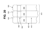
- FIGS. 19-20 show side orthographic views of a portion of a laminated rotor body stack according to embodiments of the invention.
- FIG. 21 shows a perspective view of a portion of a rotor body lamination according to the embodiment of the invention shown in, e.g., FIG. 15 .
- FIG. 22 shows a side orthographic view of a portion of a lamination according to the embodiment of the invention shown in, e.g., FIG. 15 .
- At least one embodiment of the present invention is described below in reference to its application in connection with the operation of an electric machine. Although embodiments of the invention are illustrated relative to an electric machine in the form of a generator, it is understood that the teachings are equally applicable to other electric machines including, but not limited to, motors. Further, at least one embodiment of the present invention is described below in reference to a nominal size and including a set of nominal dimensions. However, it should be apparent to those skilled in the art that the present invention is likewise applicable to any suitable generator and/or motor. Further, it should be apparent to those skilled in the art that the present invention is likewise applicable to various scales of the nominal size and/or nominal dimensions.
- FIGS. 1-3 show different aspects of a generator.
- FIG. 1 shows a three-dimensional perspective view of a portion of rotor 120 , in an embodiment which may be included in, e.g., a two pole synchronous generator.
- Rotor 120 may include a spindle 100 and groups of coils 130 disposed about spindle 100 .
- Each group of coils 130 may be contained within a plurality of slots 140 , and retained therein by coil wedges 150 .
- each group of coils 130 may contain a plurality of ducts 110 to assist in cooling coils 130 . Further aspects of the generator and rotor 120 will be described with reference to FIGS. 1-13 .
- FIG. 2 shows a cross-sectional schematic view of a generator 200 , including stator 240 , and rotor 120 positioned within stator 240 .
- Stator 240 includes groups of coils 245 , and may comprise any now known or later developed stator structure.
- rotor 120 may include spindle 100 and groups of coils 130 disposed about spindle 100 .
- Spindle 100 may be formed of, for example, iron or steel.
- Rotor 120 rotates about a longitudinal axis 250 within stator 240 .
- Rotor 120 further includes rotor body 300 , which comprises a multi-pole magnetic core. In rotor 120 depicted in FIG. 2 , the magnetic core includes two poles.
- Rotor body 300 further includes a plurality of slots 140 which contain coils 130 , forming the rotor field winding. As shown in FIG. 1 , in an embodiment, coils 130 may be held in place within slots 140 by coil wedges 150 . Coils 130 are further held in place by retaining rings 320 on each end of rotor body 300 , as depicted in FIG. 3 . In other embodiments, coils 130 may be held in place by carbon fiber rings or fiberglass banding (not shown), in which the uncured fiberglass banding material is wound under tension directly over rotor 120 and coils 130 , and then cured.
- Drive coupling 340 may be disposed between generator 200 and a source of mechanical energy, which may include a turbine or engine, and is configured to rotate rotor 120 with respect to stator 240 .
- Rotation of rotor 120 results in an electrical current being created in groups of coils 245 affixed to stator 240 ( FIG. 2 ), generating electricity.
- the current is then transmitted away from generator 200 for use in a variety of applications including, for example, powering homes and/or buildings.
- FIG. 4 shows rotor 120 according to an embodiment of the present invention, in which rotor body 300 comprises a stack 410 of a plurality of laminated plates, or laminations 415 .
- the thickness of each lamination 415 varies with the size of generator 200 .
- each lamination 415 has a first thickness measuring about 0.9525 cm (about 0.375 inch). This is merely one possible thickness of each lamination 415 , however, and is only illustrative, and not intended to exclude the use of laminations that are either thinner or thicker than described.
- the necessary and/or optimal thickness of the laminations 415 varies with the slip speed, power, and size of the electric machine in which they are used and the manufacturing method used to cut the laminations.
- laminations 415 may be suitable for, e.g., an approximately 100 megawatt generator. A generator with greater output power may utilize thinner laminations 415 than about 0.9525 cm. Typically, laminations 415 are thicker than laminations which may make up stator 240 . In one embodiment, stator 240 may comprises a plurality of stacked laminations in a fashion similar to rotor 120 , wherein each of the plurality of laminations is about 0.036 cm (about 0.014 in.) thick.
- lamination stack 410 is flanked by a first end flange member 420 located on a first end of lamination stack 410 , and by a second end flange member 425 located on a second end of lamination stack 410 .
- First and second end flange members 420 and 425 may be, but need not be, part of the magnetically active portion of rotor 120 comprising rotor body 300 .
- lamination stack 410 and first and second end flange members 420 and 425 may further be flanked by a first spacer member 430 located adjacent to the first end flange member 420 , and a second spacer member 435 located adjacent to the second end flange member 425 .
- end flange members 420 , 425 and spacer members 430 , 435 each further include a hole passing therethrough.
- end flange members 420 , 425 may include spacer members 430 , 435 , respectively, as constituent parts of the structure of the end flange members 420 , 425 . In such an embodiment, a separate spacer members 430 , 435 may not be used.
- spacer members 430 , 435 and end flange members 420 , 425 may each comprise a plurality of sub-components which together form the spacer member or end flange member structures as shown in FIG. 5 .
- stud member 440 passes through hole 510 in each of the stacked laminations 415 that comprises lamination stack 410 , as well as through the holes in each of the first and second end flange members 420 and 425 , and first and second spacer members 430 and 435 (if present).
- Stud member 440 comprises a high strength material which is able to maintain very high compression such as, for example, steel.
- stud member 440 may be threaded only on each of the ends of stud member 440 .
- First fastener 445 and second fastener 450 secure each of the ends of stud member 440 , and, together with stud member 440 , provide compression to laminated stack 410 .
- Fasteners 445 and 450 which may include nuts, torque nuts or torque bolts, or other threaded fasteners, may be tightened using any known means including but not limited to: use of hydraulic tensioning equipment, heat tightening, and so on.
- first end flange member 420 and second end flange member 425 may be shaped to provide nearly uniform pressure over an entirety of a cross section of the lamination stack 410 , the first and second end flange members 420 , 425 being tapered in thickness such that the outer diameter of each flange 420 , 425 initially contacts the outer diameter of lamination stack 410 .
- each end flange member 420 , 425 deforms so the entire face of flange 420 , 425 is in contact with the entire face of the ends of the lamination stack 410 .
- Tightening of fasteners 445 , 450 results in compression of laminated stack 410 at a pressure sufficient to provide the necessary bending stiffness to rotor body 300 and sufficient frictional capability to transmit a torque load from rotor body 300 to a drive shaft.
- the pressure necessary to accomplish this varies with the size of generator 200 , and consequently, with the size of rotor 120 . Larger machines require increased rotor stiffness, approaching that of a solid steel rotor.
- the pressures achieved are highly dependent on a variety of variables including but not limited to: the size of the rotor, the materials from which it is made, the extent to which fasteners 445 , 450 are tightened, and so on.
- a non-drive end shaft spindle 455 may be affixed to first spacer member 430
- a drive end shaft spindle 460 may be affixed to the second spacer member 435
- spacer members 430 , 435 each include a flange 465 , 470 to which spindles 455 , 460 may be affixed, respectively.
- spindles 455 , 460 may be affixed to spacer members 430 , 435 by a plurality of bolts 475 , although any known method of fixation such as welding may also be used.
- drive end spindle 460 includes drive coupling 340 ( FIG.
- spindle 455 is configured to operably connect rotor 120 to a source of mechanical energy such as, for example, a turbine, causing rotor 120 to rotate.
- a source of mechanical energy such as, for example, a turbine
- spindle 455 may also be configured to have an auxiliary drive coupling 360 ( FIG. 3 ) operably connected to rotor 120 .
- Non-drive end spindle 455 is configured to operably connect coils 130 with coil collector rings 350 ( FIG. 3 ), which are disposed about spindle 455 ( FIG. 4 ), or a brushless exciter (not shown) to provide excitation current to the rotor coils 130 .
- each lamination 415 includes a plurality of radially extending slots 140 circumferentially arranged about at least a portion of the circumference of each lamination 415 .
- FIG. 6 depicts an embodiment of a slot arrangement suited to a two pole synchronous generator.
- FIG. 7 depicts an embodiment of a slot arrangement suited to an asynchronous generator rotor having a three phase winding.
- each lamination 415 further includes a hole 510 passing through the lamination.
- the number of holes 510 may be one or greater than one.
- laminations 415 are made of steel, and may be cut using any known method, including but not limited to machining, cutting with a laser, cutting with a water jet, or punching with a die.
- the laminations may undergo further processing to coat the surface of each lamination with an insulating coating 370 (see FIGS. 10-13 ) to provide electrical isolation between adjacent laminations 415 .
- One possible insulating coating may be a phosphate based inorganic coating in accordance with ASTM C-5 electrical steel insulation.
- insulating coatings may include EB 500FF C-6, EB5001 C-6, EB5300 C-5, among other possible insulating coatings.
- insulating coating 370 may measure between about 0.001 mm and about 0.020 mm in thickness.
- the laminations 415 depicted in FIGS. 6-8 show embodiments in which rotor coils 130 are held in place within slots 140 by coil wedges 150 , however other embodiments may include, e.g., carbon fiber rings or fiberglass banding to hold coils 130 in slots 140 as discussed above.
- laminations 415 include surface 550 in slot 140 , where lamination 415 mates with wedge 150 .
- Lamination 415 may be machined to create surface 550 and so avoid concentration of stress at points along the interface with wedge 150 ( FIG. 9 ).
- surface 550 may include first chamfer 520 .
- First chamfer 520 connects surface 550 and a first face 418 of the lamination ( FIG. 11 ) on an angle which may be approximately 45° in one embodiment. Other embodiments in which the angle is more or less than 45° are also used.
- First chamfer 520 may be cut along line B-B (labeled in FIG. 10 ) such that first chamfers 520 physically separate successive laminations 415 in a stack 410 of laminations as shown in FIGS. 13-14 .
- FIGS. 13-14 show a view of laminations 415 cut along plane A-A (labeled in FIG. 10 ).
- first chamfers 520 may be filled with insulating material 530 to further aid in avoiding smearing across insulating coatings 370 between laminations 415 , which may take place during machining of, e.g., surface 550 .
- insulating material 530 may be epoxy.
- FIG. 14 shows laminations 415 from the same view as FIG. 13 (along plane A-A as labeled in FIG. 10 ). In FIG. 14 , laminations 415 have been machined to create surface 550 .
- double sided, i.e., symmetrical first chamfers 540 may be used instead of the single sided, i.e., asymmetrical first chamfers 520 illustrated in FIGS. 11-14 .
- Double-sided first chamfer 540 connects surface 550 with first face 418 of lamination 415 and second, opposing face 422 of lamination 415 ( FIG. 15 ).
- Double-sided first chamfers 540 provide for increased axial distance between laminations 415 and may further decrease likelihood of smearing.
- double-sided first chamfers 540 may be filled with insulating material 530 and machined ( FIGS. 15-16 ) as described above.
- laminations 415 may additionally include second chamfer 521 at an outer diameter of lamination 415 .
- Second chamfer 521 connects first face 418 of lamination 415 with outer circumference surface 525 of lamination 415 .
- second chamfer 521 may reduce the occurrence of smearing across laminations 415 by increasing the axial distance between the laminations 415 at the outer diameter of stack 410 .
- FIGS. 17-19 depict a single sided chamfer 521 , however, a double sided second chamfer 522 ( FIG.
- second chamfers 521 , 522 may also be filled with insulating material 530 .
- a rotor body 300 is assembled, including assembling a stack 410 of a plurality of laminations 415 , and inserting a stud member 440 through a hole 510 in each of the plurality of laminations 415 .
- Each of the plurality of laminations 415 includes a plurality of radially extending slots 140 arranged about a circumference of each of the plurality of laminations 415 .
- Each of the plurality of laminations 415 may further include a first chamfer 520 on a face of each of the laminations 415 , or a first chamfer 540 on both faces of each of the laminations 415 .
- first chamfer 520 may be filled with an insulating material 530 , which may be an epoxy.
- second chamfers 521 , 522 may be provided at the outer diameter of each lamination 415 , which may be single- or double-sided.
- a number of surfaces of the assembled rotor body 300 may be machined, for a variety of purposes, including, e.g., surface 550 of lamination 415 , at the interface between wedge 150 and lamination 415 (see FIG. 9 ) and the outer circumference surface 525 of rotor body 300 ( FIGS. 17-19 ).
- FIGS. 13-16 provide a more detailed view of the machining of the laminations 415 to achieve uniform contacts.
- the step of filling first chamfers 520 , 540 and second chamfers 521 , 522 if present in each of the plurality of laminations 415 with insulating material 530 occurs after assembly of rotor body 300 but prior to machining at least one surface of laminations 415 /rotor body 300 .
- the terms “first,” “second,” and the like do not denote any order, quantity, or importance, but rather are used to distinguish one element from another, and the terms “a” and “an” herein do not denote a limitation of quantity, but rather denote the presence of at least one of the referenced item.
- the modifier “about” used in connection with a quantity is inclusive of the stated value and has the meaning dictated by the context (e.g., includes the degree of error associated with measurement of the particular quantity).
- the suffix “(s)” as used herein is intended to include both the singular and the plural of the term that it modifies, thereby including one or more of that term (e.g., the metal(s) includes one or more metals).
- Ranges disclosed herein are inclusive and independently combinable (e.g., ranges of “up to about 25 mm, or, more specifically, about 5 mm to about 20 mm,” is inclusive of the endpoints and all intermediate values of the ranges of “about 5 mm to about 25 mm,” etc.).
Abstract
Description
Claims (20)
Applications Claiming Priority (1)
| Application Number | Priority Date | Filing Date | Title |
|---|---|---|---|
| PCT/RU2011/000492 WO2013006079A1 (en) | 2011-07-06 | 2011-07-06 | Laminated rotor machining enhancement |
Publications (2)
| Publication Number | Publication Date |
|---|---|
| US20140232234A1 US20140232234A1 (en) | 2014-08-21 |
| US9190879B2 true US9190879B2 (en) | 2015-11-17 |
Family
ID=45562418
Family Applications (1)
| Application Number | Title | Priority Date | Filing Date |
|---|---|---|---|
| US13/823,054 Active 2031-07-18 US9190879B2 (en) | 2011-07-06 | 2011-07-06 | Laminated rotor machining enhancement |
Country Status (5)
| Country | Link |
|---|---|
| US (1) | US9190879B2 (en) |
| EP (1) | EP2730008B1 (en) |
| KR (1) | KR101766519B1 (en) |
| RU (1) | RU2556246C1 (en) |
| WO (1) | WO2013006079A1 (en) |
Cited By (1)
| Publication number | Priority date | Publication date | Assignee | Title |
|---|---|---|---|---|
| EP3633826A1 (en) | 2018-10-03 | 2020-04-08 | GE Energy Power Conversion Technology Ltd. | Rotor with non-through shaft, rotor assembly, rotor with multiple magnetic masses and associated rotating electrical machine |
Families Citing this family (3)
| Publication number | Priority date | Publication date | Assignee | Title |
|---|---|---|---|---|
| GB2506784A (en) | 2011-07-06 | 2014-04-09 | Gen Electric | Laminated rotor balancing provisions |
| KR101628150B1 (en) * | 2014-11-14 | 2016-06-21 | 현대자동차 주식회사 | Rotor structure of wrsm motor |
| DE102016222356A1 (en) * | 2016-11-15 | 2018-05-17 | Bayerische Motoren Werke Aktiengesellschaft | Rotor for an electric machine with retractable windings |
Citations (105)
| Publication number | Priority date | Publication date | Assignee | Title |
|---|---|---|---|---|
| US383659A (en) | 1888-05-29 | Armature for dynamos | ||
| US464026A (en) | 1891-12-01 | Transformer and armature-core | ||
| US780085A (en) | 1904-05-14 | 1905-01-17 | Bullock Electric Mfg Co | Dynamo-electric machine. |
| US932083A (en) | 1907-02-28 | 1909-08-24 | Allis Chalmers | Turbo-rotor. |
| US1028985A (en) | 1905-08-21 | 1912-06-11 | Allis Chalmers | Dynamo-electric machine. |
| GB381641A (en) | 1930-08-04 | 1932-10-13 | Bbc Brown Boveri & Cie | Improvements in or relating to rotors for dynamo-electric machines |
| US2064033A (en) * | 1934-08-15 | 1936-12-15 | Westinghouse Electric & Mfg Co | Turbine generator rotor |
| US3119033A (en) | 1961-11-07 | 1964-01-21 | Parsons C A & Co Ltd | Dynamo-electric machines |
| US3763386A (en) | 1972-04-06 | 1973-10-02 | Airtrol Corp | Unit bearing motor |
| US3783317A (en) | 1972-11-22 | 1974-01-01 | Wagner Electric Corp | Dynamoelectric machine rotor |
| US3965382A (en) | 1974-10-03 | 1976-06-22 | General Electric Company | Rotor having balance weights |
| US4121926A (en) | 1975-11-18 | 1978-10-24 | Sumitomo Aluminum Smelting Company, Limited | Squirrel-cage rotor |
| US4152610A (en) | 1973-08-22 | 1979-05-01 | Patentbureau Danubia | Turbogenerator having dual cooling |
| DE2815214A1 (en) | 1978-03-21 | 1979-10-04 | Bbc Brown Boveri & Cie | Laminated core for rotary electric machine - has triangular wedge slots enclosing sharp angle and forming rounded apex |
| JPS5534857A (en) | 1978-09-04 | 1980-03-11 | Hitachi Ltd | Rotor for outer-rotor magnet generator and its manufacturing method |
| US4259603A (en) | 1977-02-25 | 1981-03-31 | Sony Corporation | Electric motor |
| DE3013704A1 (en) | 1980-04-10 | 1981-10-15 | Interelectric Ag, Sachseln | BALANCED ROTOR |
| US4298812A (en) | 1978-11-03 | 1981-11-03 | Alsthom-Atlantique | Gas cooled rotor for an electric machine |
| JPS5754A (en) | 1980-06-02 | 1982-01-05 | Toshiba Corp | Balancing method for rotor |
| US4315301A (en) | 1978-10-16 | 1982-02-09 | Jimena Carlos L | Generator flashlight |
| JPS5746661A (en) | 1980-08-31 | 1982-03-17 | Yamaha Motor Co Ltd | Cylindrical rotor for power generator |
| JPS5791656A (en) | 1980-11-27 | 1982-06-07 | Toshiba Corp | Manufacture of rotor for rotary electric machine |
| US4363986A (en) | 1979-07-26 | 1982-12-14 | Bbc Brown, Boveri & Company, Limited | Rotor of an electrical machine |
| JPS5851759A (en) | 1981-09-24 | 1983-03-26 | Mitsubishi Electric Corp | Rotor for rotary electric machine |
| US4489249A (en) | 1982-03-26 | 1984-12-18 | Alsthom-Atlantique | Electric machine rotor having a laminated and segmented rim |
| JPS605764A (en) | 1983-06-22 | 1985-01-12 | Hitachi Ltd | Squirrel-cage rotor |
| JPS6035946A (en) | 1983-08-05 | 1985-02-23 | Sanyo Electric Co Ltd | Permanent magnet synchronous motor |
| WO1985000938A1 (en) | 1983-08-17 | 1985-02-28 | Sundstrand Corporation | High speed rotor and method of refurbishment |
| US4503377A (en) | 1983-01-14 | 1985-03-05 | Hitachi, Ltd. | Variable speed rotary electric machine |
| JPS6077646A (en) | 1983-09-30 | 1985-05-02 | Aichi Emason Denki Kk | Core blank punching method of brushless motor |
| US4614888A (en) | 1983-08-17 | 1986-09-30 | Sundstrand Corporation | Improved magnetic rotor |
| US4642886A (en) | 1983-08-01 | 1987-02-17 | Siemens Aktiengesellschaft | Method for balancing wound rotors of electrical machines |
| US4761580A (en) * | 1987-06-17 | 1988-08-02 | Magnetek, Inc. | Magnetic top wedge |
| EP0320304A1 (en) | 1987-12-10 | 1989-06-14 | General Electric Company | Conductive metal inserts in rotor of dynamoelectric machine |
| US4922147A (en) | 1988-11-25 | 1990-05-01 | Westinghouse Electric Corp. | Apparatus and method for thermal balancing of the rotor of a dynamo-electric machine |
| JPH02188157A (en) | 1988-11-02 | 1990-07-24 | Carrier Corp | Rolling rotor type motor |
| US5030871A (en) * | 1990-05-11 | 1991-07-09 | General Electric Company | Reducing harmonic losses in dynamoelectric machine rotors |
| EP0461733A2 (en) | 1986-04-18 | 1991-12-18 | Cybernetics Products, Inc. | High speed precision drilling system |
| JPH0421338A (en) | 1990-05-15 | 1992-01-24 | Toshiba Corp | Bipolar rotor for rotary electric machine |
| EP0484026A2 (en) | 1990-10-29 | 1992-05-06 | General Electric Company | Retaining ring for electric machine |
| JPH04178132A (en) | 1990-11-08 | 1992-06-25 | Asmo Co Ltd | Winding of revolving armature |
| US5174011A (en) | 1991-03-27 | 1992-12-29 | Klaus Weigelt | Method for preparing the rotor of a turbogenerator |
| EP0538472A1 (en) | 1990-07-12 | 1993-04-28 | Seiko Epson Corporation | Rotor of brushless motor and manufacture thereof |
| JPH05252679A (en) | 1992-03-02 | 1993-09-28 | Jidosha Denki Kogyo Co Ltd | Armature for miniature motor |
| EP0565312A2 (en) | 1992-04-06 | 1993-10-13 | General Electric Company | Integral motor and control |
| EP0577843A1 (en) | 1992-01-27 | 1994-01-12 | Kabushikigaisha Sekogiken | Reluctance motor and rotor of high-speed reluctance motor |
| EP0595609A1 (en) | 1992-10-29 | 1994-05-04 | General Electric Company | Rotor winding |
| EP0632566A1 (en) | 1993-06-30 | 1995-01-04 | Simmonds Precision Engine Systems, Inc. | Apparatus and methods for heat dissipation in electromechanical devices |
| EP0646937A1 (en) | 1990-11-30 | 1995-04-05 | Intermetallics Co., Ltd. | Method for producing a permanent magnet and an apparatus for producing a green compact |
| EP0657984A1 (en) | 1992-08-12 | 1995-06-14 | Seiko Epson Corporation | Permanent magnet rotor of brushless motor and production method thereof |
| EP0658895A2 (en) | 1993-12-14 | 1995-06-21 | Hitachi, Ltd. | Recording disk apparatus and rotational supporting structure therefor |
| US5495133A (en) | 1993-01-26 | 1996-02-27 | Gec Alsthon Acec Energie | Electric motor with high power and high rotational speed |
| EP0712198A1 (en) | 1994-06-01 | 1996-05-15 | Seiko Epson Corporation | Permanent magnet rotor and method for producing the same |
| EP0728956A1 (en) | 1995-02-17 | 1996-08-28 | Seiko Epson Corporation | Superconducting bearing device and method of producing the same |
| US5559419A (en) | 1993-12-22 | 1996-09-24 | Wisconsin Alumni Research Foundation | Method and apparatus for transducerless flux estimation in drives for induction machines |
| US5685063A (en) | 1994-11-04 | 1997-11-11 | General Electric Company | Method of forming rotor-winding for a dynamoelectric machine |
| EP0823771A1 (en) | 1996-02-23 | 1998-02-11 | Matsushita Electric Industrial Co., Ltd. | Motor |
| US5742515A (en) | 1995-04-21 | 1998-04-21 | General Electric Co. | Asynchronous conversion method and apparatus for use with variable speed turbine hydroelectric generation |
| EP0872944A1 (en) | 1997-04-14 | 1998-10-21 | Sanyo Electric Co., Ltd. | Rotor of electric motor |
| JPH10290556A (en) | 1997-04-14 | 1998-10-27 | Hitachi Ltd | Squirrel-cage rotor |
| US5886443A (en) | 1997-12-03 | 1999-03-23 | General Electric Canada Inc. | Spark suppression of induction type rotors of dynamoelectric machines |
| US5892306A (en) | 1997-03-24 | 1999-04-06 | Emerson Electric Co. | Method and apparatus for balancing a load with a salient pole rotor machine |
| US5894183A (en) | 1996-10-29 | 1999-04-13 | Caterpillar Inc. | Permanent magnet generator rotor |
| US6082186A (en) | 1997-04-23 | 2000-07-04 | Ncr Corporation | Adjustable balance weight |
| EP0622885B1 (en) | 1993-04-30 | 2000-09-20 | Sanyo Electric Co. Ltd | Rotor of electric motor for compressor |
| US6177750B1 (en) | 1998-07-14 | 2001-01-23 | Reliance Electric Technologies, Llc | Rotating assembly construction for high speed induction motor |
| US6265805B1 (en) | 1997-02-07 | 2001-07-24 | Jeumont Industrie | Rotor shaft of synchronous electric machine |
| US20020057027A1 (en) | 2000-06-30 | 2002-05-16 | Mclaren Donald Gordon | Rotating variable frequency transformer with high voltage cables |
| US6459180B1 (en) | 1999-09-17 | 2002-10-01 | Hitachi, Ltd. | Rotary electric power generator |
| US20030094872A1 (en) | 2001-11-16 | 2003-05-22 | Tornquist Gerald Eugene | Rotor end caps and a method of cooling a high speed generator |
| US20030102762A1 (en) | 1998-08-03 | 2003-06-05 | Jansen Patrick Lee | Sensorless control induction motor rotor slot shapes and fabrication methods |
| US6628005B2 (en) | 2001-09-27 | 2003-09-30 | Siemens Westinghouse Power Corporation | Single speed turbine generator for different power system output frequencies in power generation systems and associated methods |
| US20030201646A1 (en) | 2002-04-29 | 2003-10-30 | Solomon Kaploun | All-weather energy and water production via steam-enhanced vortex tower |
| US6710497B2 (en) | 2001-10-16 | 2004-03-23 | General Electric Company | Apparatus and method for a field winding assembly mountable on a rotor in a synchronous machine |
| JP2004140966A (en) | 2002-10-21 | 2004-05-13 | Nissan Motor Co Ltd | Lamination structure of core for rotating electric machine |
| US6774522B2 (en) * | 2002-02-21 | 2004-08-10 | Hitachi, Ltd. | Rotor with slot wedges having different dimension to reduce stress |
| WO2004079882A1 (en) | 2003-03-06 | 2004-09-16 | General Electric Canada Inc. | Insulated core stud for rotor and stator laminations |
| JP2004343919A (en) | 2003-05-16 | 2004-12-02 | Denso Corp | Rotor for dc motor |
| EP1541739A2 (en) | 2003-12-10 | 2005-06-15 | LG Electronics Inc. | Drum type washer with a position sensor |
| JP2005229767A (en) | 2004-02-16 | 2005-08-25 | Mitsubishi Electric Corp | Rotating electric machine |
| US20060214645A1 (en) | 2003-07-05 | 2006-09-28 | Alstom Technology Ltd | Frequency converter for high-speed generators |
| JP2006288061A (en) | 2005-03-31 | 2006-10-19 | Canon Inc | Electric-mechanical energy conversion element, stacked piezoelectric element, vibration wave driver, and manufacturing method of stacked piezoelectric element |
| US20060267441A1 (en) | 2005-05-26 | 2006-11-30 | Baiying Hang | Self-start synchronous motor, method for manufacturing the same and compressor |
| EP1796247A2 (en) | 2005-12-08 | 2007-06-13 | Fanuc Ltd | Mold used for manufacturing electric motor rotor |
| US7275442B2 (en) * | 2005-04-21 | 2007-10-02 | General Electric Company | Method for ultrasonic inspection of generator field teeth |
| JP4021338B2 (en) | 2003-02-12 | 2007-12-12 | 株式会社ケンウッド | DC output offset detection circuit for BTL connection amplifier |
| EP1906509A2 (en) | 2006-09-28 | 2008-04-02 | Hitachi, Ltd. | Rotating electrical machine and alternating-current generator |
| EP1947758A2 (en) | 2007-01-19 | 2008-07-23 | Fanuc Ltd | Method of manufacturing rotor of electric motor and electric motor |
| EP1962326A1 (en) | 2005-12-12 | 2008-08-27 | Asahi Glass Company, Limited | Reflection-type mask blank for euv lithography, and substrate with electrically conductive film for the mask blank |
| JP4178132B2 (en) | 2004-07-07 | 2008-11-12 | 日立オムロンターミナルソリューションズ株式会社 | Paper sheet stacking and separating device |
| EP1998425A2 (en) | 2007-05-28 | 2008-12-03 | Kabushiki Kaisha Toshiba | Rotor of a turbo generator |
| US20090123282A1 (en) | 2007-11-08 | 2009-05-14 | General Electric Company | Rotating machine balancing member assembly including multiple interlocking balancing members |
| EP2083503A2 (en) | 2008-01-22 | 2009-07-29 | LG Electronics Inc. | Brushless direct current motor |
| EP2096735A1 (en) | 2006-12-06 | 2009-09-02 | Honda Motor Co., Ltd | Axial gap motor |
| EP2099115A2 (en) | 2008-03-04 | 2009-09-09 | Hitachi Ltd. | Electric rotating machine and hybrid car provided with the same |
| EP2113987A1 (en) | 2007-02-23 | 2009-11-04 | Daikin Industries, Ltd. | Insulator for motor, stator, motor and compressor |
| US7626309B2 (en) | 2007-09-12 | 2009-12-01 | Canopy Technologies, Llc | Method of balancing an embedded permanent magnet motor rotor |
| US7692352B2 (en) | 2007-09-04 | 2010-04-06 | General Electric Company | Apparatus and method for cooling rotor and stator motor cores |
| JP2010130842A (en) | 2008-11-28 | 2010-06-10 | Sanko Kiki Co Ltd | Stator core and stator core with coil |
| JP2010148294A (en) | 2008-12-21 | 2010-07-01 | Sanyo Electric Co Ltd | Rotor of electric motor |
| US20100281688A1 (en) | 2007-11-19 | 2010-11-11 | Alstom Technology Ltd | Process for producing a rotor |
| US20110080068A1 (en) * | 2009-10-06 | 2011-04-07 | General Electric Company | Laminated generator rotor structure and related method |
| WO2013006078A1 (en) | 2011-07-06 | 2013-01-10 | General Electric Company | Laminated rotor balancing provisions |
| JP5252679B2 (en) | 2007-08-31 | 2013-07-31 | 株式会社ユニバーサルエンターテインメント | Game machine |
| WO2013112067A1 (en) | 2012-01-26 | 2013-08-01 | General Electric Company | Dynamoelectric machine having enhanced rotor ventilation |
Family Cites Families (2)
| Publication number | Priority date | Publication date | Assignee | Title |
|---|---|---|---|---|
| FR2761211B1 (en) * | 1997-03-20 | 1999-06-04 | Centre Nat Rech Scient | ROTATING ELECTRIC MACHINE EXCITING BY WINDINGS, BY MAGNETS OR DOUBLE EXCITATION |
| DE102008004876A1 (en) * | 2007-02-01 | 2008-08-07 | Robert Bosch Gmbh | Electric machine |
-
2011
- 2011-07-06 US US13/823,054 patent/US9190879B2/en active Active
- 2011-07-06 EP EP11815734.6A patent/EP2730008B1/en active Active
- 2011-07-06 RU RU2013158011/07A patent/RU2556246C1/en not_active IP Right Cessation
- 2011-07-06 WO PCT/RU2011/000492 patent/WO2013006079A1/en active Application Filing
- 2011-07-06 KR KR1020147000206A patent/KR101766519B1/en active IP Right Grant
Patent Citations (113)
| Publication number | Priority date | Publication date | Assignee | Title |
|---|---|---|---|---|
| US383659A (en) | 1888-05-29 | Armature for dynamos | ||
| US464026A (en) | 1891-12-01 | Transformer and armature-core | ||
| US780085A (en) | 1904-05-14 | 1905-01-17 | Bullock Electric Mfg Co | Dynamo-electric machine. |
| US1028985A (en) | 1905-08-21 | 1912-06-11 | Allis Chalmers | Dynamo-electric machine. |
| US932083A (en) | 1907-02-28 | 1909-08-24 | Allis Chalmers | Turbo-rotor. |
| GB381641A (en) | 1930-08-04 | 1932-10-13 | Bbc Brown Boveri & Cie | Improvements in or relating to rotors for dynamo-electric machines |
| US2064033A (en) * | 1934-08-15 | 1936-12-15 | Westinghouse Electric & Mfg Co | Turbine generator rotor |
| US3119033A (en) | 1961-11-07 | 1964-01-21 | Parsons C A & Co Ltd | Dynamo-electric machines |
| US3763386A (en) | 1972-04-06 | 1973-10-02 | Airtrol Corp | Unit bearing motor |
| US3783317A (en) | 1972-11-22 | 1974-01-01 | Wagner Electric Corp | Dynamoelectric machine rotor |
| US4152610A (en) | 1973-08-22 | 1979-05-01 | Patentbureau Danubia | Turbogenerator having dual cooling |
| US3965382A (en) | 1974-10-03 | 1976-06-22 | General Electric Company | Rotor having balance weights |
| US4121926A (en) | 1975-11-18 | 1978-10-24 | Sumitomo Aluminum Smelting Company, Limited | Squirrel-cage rotor |
| US4259603A (en) | 1977-02-25 | 1981-03-31 | Sony Corporation | Electric motor |
| DE2815214A1 (en) | 1978-03-21 | 1979-10-04 | Bbc Brown Boveri & Cie | Laminated core for rotary electric machine - has triangular wedge slots enclosing sharp angle and forming rounded apex |
| JPS5534857A (en) | 1978-09-04 | 1980-03-11 | Hitachi Ltd | Rotor for outer-rotor magnet generator and its manufacturing method |
| US4315301A (en) | 1978-10-16 | 1982-02-09 | Jimena Carlos L | Generator flashlight |
| US4298812A (en) | 1978-11-03 | 1981-11-03 | Alsthom-Atlantique | Gas cooled rotor for an electric machine |
| US4363986A (en) | 1979-07-26 | 1982-12-14 | Bbc Brown, Boveri & Company, Limited | Rotor of an electrical machine |
| DE3013704A1 (en) | 1980-04-10 | 1981-10-15 | Interelectric Ag, Sachseln | BALANCED ROTOR |
| JPS5754A (en) | 1980-06-02 | 1982-01-05 | Toshiba Corp | Balancing method for rotor |
| JPS5746661A (en) | 1980-08-31 | 1982-03-17 | Yamaha Motor Co Ltd | Cylindrical rotor for power generator |
| JPS5791656A (en) | 1980-11-27 | 1982-06-07 | Toshiba Corp | Manufacture of rotor for rotary electric machine |
| JPS5851759A (en) | 1981-09-24 | 1983-03-26 | Mitsubishi Electric Corp | Rotor for rotary electric machine |
| US4489249A (en) | 1982-03-26 | 1984-12-18 | Alsthom-Atlantique | Electric machine rotor having a laminated and segmented rim |
| US4503377A (en) | 1983-01-14 | 1985-03-05 | Hitachi, Ltd. | Variable speed rotary electric machine |
| JPS605764A (en) | 1983-06-22 | 1985-01-12 | Hitachi Ltd | Squirrel-cage rotor |
| US4642886A (en) | 1983-08-01 | 1987-02-17 | Siemens Aktiengesellschaft | Method for balancing wound rotors of electrical machines |
| JPS6035946A (en) | 1983-08-05 | 1985-02-23 | Sanyo Electric Co Ltd | Permanent magnet synchronous motor |
| WO1985000938A1 (en) | 1983-08-17 | 1985-02-28 | Sundstrand Corporation | High speed rotor and method of refurbishment |
| US4614888A (en) | 1983-08-17 | 1986-09-30 | Sundstrand Corporation | Improved magnetic rotor |
| JPS6077646A (en) | 1983-09-30 | 1985-05-02 | Aichi Emason Denki Kk | Core blank punching method of brushless motor |
| EP0461733A2 (en) | 1986-04-18 | 1991-12-18 | Cybernetics Products, Inc. | High speed precision drilling system |
| US4761580A (en) * | 1987-06-17 | 1988-08-02 | Magnetek, Inc. | Magnetic top wedge |
| EP0320304A1 (en) | 1987-12-10 | 1989-06-14 | General Electric Company | Conductive metal inserts in rotor of dynamoelectric machine |
| JPH02188157A (en) | 1988-11-02 | 1990-07-24 | Carrier Corp | Rolling rotor type motor |
| US4922147A (en) | 1988-11-25 | 1990-05-01 | Westinghouse Electric Corp. | Apparatus and method for thermal balancing of the rotor of a dynamo-electric machine |
| US5030871A (en) * | 1990-05-11 | 1991-07-09 | General Electric Company | Reducing harmonic losses in dynamoelectric machine rotors |
| JPH0421338A (en) | 1990-05-15 | 1992-01-24 | Toshiba Corp | Bipolar rotor for rotary electric machine |
| EP0538472A1 (en) | 1990-07-12 | 1993-04-28 | Seiko Epson Corporation | Rotor of brushless motor and manufacture thereof |
| EP0538472B1 (en) | 1990-07-12 | 1997-10-29 | Seiko Epson Corporation | Rotor of brushless motor and manufacture thereof |
| EP0484026A2 (en) | 1990-10-29 | 1992-05-06 | General Electric Company | Retaining ring for electric machine |
| JPH04178132A (en) | 1990-11-08 | 1992-06-25 | Asmo Co Ltd | Winding of revolving armature |
| EP0646937A1 (en) | 1990-11-30 | 1995-04-05 | Intermetallics Co., Ltd. | Method for producing a permanent magnet and an apparatus for producing a green compact |
| US5174011A (en) | 1991-03-27 | 1992-12-29 | Klaus Weigelt | Method for preparing the rotor of a turbogenerator |
| EP0577843A1 (en) | 1992-01-27 | 1994-01-12 | Kabushikigaisha Sekogiken | Reluctance motor and rotor of high-speed reluctance motor |
| EP0577843B1 (en) | 1992-01-27 | 1998-03-18 | Kabushikigaisha Sekogiken | High-speed reluctance motor |
| JPH05252679A (en) | 1992-03-02 | 1993-09-28 | Jidosha Denki Kogyo Co Ltd | Armature for miniature motor |
| EP0565312A2 (en) | 1992-04-06 | 1993-10-13 | General Electric Company | Integral motor and control |
| EP0657984A1 (en) | 1992-08-12 | 1995-06-14 | Seiko Epson Corporation | Permanent magnet rotor of brushless motor and production method thereof |
| EP0595609A1 (en) | 1992-10-29 | 1994-05-04 | General Electric Company | Rotor winding |
| US5495133A (en) | 1993-01-26 | 1996-02-27 | Gec Alsthon Acec Energie | Electric motor with high power and high rotational speed |
| EP0622885B1 (en) | 1993-04-30 | 2000-09-20 | Sanyo Electric Co. Ltd | Rotor of electric motor for compressor |
| EP0632566A1 (en) | 1993-06-30 | 1995-01-04 | Simmonds Precision Engine Systems, Inc. | Apparatus and methods for heat dissipation in electromechanical devices |
| EP0658895A2 (en) | 1993-12-14 | 1995-06-21 | Hitachi, Ltd. | Recording disk apparatus and rotational supporting structure therefor |
| US5559419A (en) | 1993-12-22 | 1996-09-24 | Wisconsin Alumni Research Foundation | Method and apparatus for transducerless flux estimation in drives for induction machines |
| EP0712198A1 (en) | 1994-06-01 | 1996-05-15 | Seiko Epson Corporation | Permanent magnet rotor and method for producing the same |
| US5685063A (en) | 1994-11-04 | 1997-11-11 | General Electric Company | Method of forming rotor-winding for a dynamoelectric machine |
| EP0728956A1 (en) | 1995-02-17 | 1996-08-28 | Seiko Epson Corporation | Superconducting bearing device and method of producing the same |
| US5742515A (en) | 1995-04-21 | 1998-04-21 | General Electric Co. | Asynchronous conversion method and apparatus for use with variable speed turbine hydroelectric generation |
| EP0823771A1 (en) | 1996-02-23 | 1998-02-11 | Matsushita Electric Industrial Co., Ltd. | Motor |
| US5894183A (en) | 1996-10-29 | 1999-04-13 | Caterpillar Inc. | Permanent magnet generator rotor |
| US6265805B1 (en) | 1997-02-07 | 2001-07-24 | Jeumont Industrie | Rotor shaft of synchronous electric machine |
| US5892306A (en) | 1997-03-24 | 1999-04-06 | Emerson Electric Co. | Method and apparatus for balancing a load with a salient pole rotor machine |
| JPH10290556A (en) | 1997-04-14 | 1998-10-27 | Hitachi Ltd | Squirrel-cage rotor |
| EP0872944A1 (en) | 1997-04-14 | 1998-10-21 | Sanyo Electric Co., Ltd. | Rotor of electric motor |
| EP0872944B1 (en) | 1997-04-14 | 2008-05-21 | Sanyo Electric Co., Ltd. | Rotor of electric motor |
| US6082186A (en) | 1997-04-23 | 2000-07-04 | Ncr Corporation | Adjustable balance weight |
| US5886443A (en) | 1997-12-03 | 1999-03-23 | General Electric Canada Inc. | Spark suppression of induction type rotors of dynamoelectric machines |
| US6177750B1 (en) | 1998-07-14 | 2001-01-23 | Reliance Electric Technologies, Llc | Rotating assembly construction for high speed induction motor |
| US20030102762A1 (en) | 1998-08-03 | 2003-06-05 | Jansen Patrick Lee | Sensorless control induction motor rotor slot shapes and fabrication methods |
| US6459180B1 (en) | 1999-09-17 | 2002-10-01 | Hitachi, Ltd. | Rotary electric power generator |
| US20020057027A1 (en) | 2000-06-30 | 2002-05-16 | Mclaren Donald Gordon | Rotating variable frequency transformer with high voltage cables |
| US6628005B2 (en) | 2001-09-27 | 2003-09-30 | Siemens Westinghouse Power Corporation | Single speed turbine generator for different power system output frequencies in power generation systems and associated methods |
| US6710497B2 (en) | 2001-10-16 | 2004-03-23 | General Electric Company | Apparatus and method for a field winding assembly mountable on a rotor in a synchronous machine |
| US20030094872A1 (en) | 2001-11-16 | 2003-05-22 | Tornquist Gerald Eugene | Rotor end caps and a method of cooling a high speed generator |
| US6734585B2 (en) | 2001-11-16 | 2004-05-11 | Honeywell International, Inc. | Rotor end caps and a method of cooling a high speed generator |
| US20040164627A1 (en) | 2001-11-16 | 2004-08-26 | Tornquist Gerald Eugene | Rotor end caps and a method of cooling a high speed generator |
| US6774522B2 (en) * | 2002-02-21 | 2004-08-10 | Hitachi, Ltd. | Rotor with slot wedges having different dimension to reduce stress |
| US20030201646A1 (en) | 2002-04-29 | 2003-10-30 | Solomon Kaploun | All-weather energy and water production via steam-enhanced vortex tower |
| JP2004140966A (en) | 2002-10-21 | 2004-05-13 | Nissan Motor Co Ltd | Lamination structure of core for rotating electric machine |
| JP4021338B2 (en) | 2003-02-12 | 2007-12-12 | 株式会社ケンウッド | DC output offset detection circuit for BTL connection amplifier |
| WO2004079882A1 (en) | 2003-03-06 | 2004-09-16 | General Electric Canada Inc. | Insulated core stud for rotor and stator laminations |
| JP2004343919A (en) | 2003-05-16 | 2004-12-02 | Denso Corp | Rotor for dc motor |
| US20060214645A1 (en) | 2003-07-05 | 2006-09-28 | Alstom Technology Ltd | Frequency converter for high-speed generators |
| US20050126230A1 (en) | 2003-12-10 | 2005-06-16 | Choi Seung B. | Drum type washer |
| EP1541739A2 (en) | 2003-12-10 | 2005-06-15 | LG Electronics Inc. | Drum type washer with a position sensor |
| US7562542B2 (en) | 2003-12-10 | 2009-07-21 | Lg Electronics Inc. | Drum type washer |
| JP2005229767A (en) | 2004-02-16 | 2005-08-25 | Mitsubishi Electric Corp | Rotating electric machine |
| JP4178132B2 (en) | 2004-07-07 | 2008-11-12 | 日立オムロンターミナルソリューションズ株式会社 | Paper sheet stacking and separating device |
| JP2006288061A (en) | 2005-03-31 | 2006-10-19 | Canon Inc | Electric-mechanical energy conversion element, stacked piezoelectric element, vibration wave driver, and manufacturing method of stacked piezoelectric element |
| US7275442B2 (en) * | 2005-04-21 | 2007-10-02 | General Electric Company | Method for ultrasonic inspection of generator field teeth |
| US20060267441A1 (en) | 2005-05-26 | 2006-11-30 | Baiying Hang | Self-start synchronous motor, method for manufacturing the same and compressor |
| US7531934B2 (en) | 2005-05-26 | 2009-05-12 | Hitachi Appliances, Inc. | Self-start synchronous motor with permanent magnets and at least one frictional agitation joint, method for manufacturing the same and compressor comprising the same |
| EP1796247A2 (en) | 2005-12-08 | 2007-06-13 | Fanuc Ltd | Mold used for manufacturing electric motor rotor |
| EP1962326A1 (en) | 2005-12-12 | 2008-08-27 | Asahi Glass Company, Limited | Reflection-type mask blank for euv lithography, and substrate with electrically conductive film for the mask blank |
| EP1906509A2 (en) | 2006-09-28 | 2008-04-02 | Hitachi, Ltd. | Rotating electrical machine and alternating-current generator |
| EP2096735A1 (en) | 2006-12-06 | 2009-09-02 | Honda Motor Co., Ltd | Axial gap motor |
| EP1947758A2 (en) | 2007-01-19 | 2008-07-23 | Fanuc Ltd | Method of manufacturing rotor of electric motor and electric motor |
| EP2113987A1 (en) | 2007-02-23 | 2009-11-04 | Daikin Industries, Ltd. | Insulator for motor, stator, motor and compressor |
| EP1998425A2 (en) | 2007-05-28 | 2008-12-03 | Kabushiki Kaisha Toshiba | Rotor of a turbo generator |
| JP5252679B2 (en) | 2007-08-31 | 2013-07-31 | 株式会社ユニバーサルエンターテインメント | Game machine |
| US7692352B2 (en) | 2007-09-04 | 2010-04-06 | General Electric Company | Apparatus and method for cooling rotor and stator motor cores |
| US7626309B2 (en) | 2007-09-12 | 2009-12-01 | Canopy Technologies, Llc | Method of balancing an embedded permanent magnet motor rotor |
| US20090123282A1 (en) | 2007-11-08 | 2009-05-14 | General Electric Company | Rotating machine balancing member assembly including multiple interlocking balancing members |
| US20100281688A1 (en) | 2007-11-19 | 2010-11-11 | Alstom Technology Ltd | Process for producing a rotor |
| EP2083503A2 (en) | 2008-01-22 | 2009-07-29 | LG Electronics Inc. | Brushless direct current motor |
| EP2099115A2 (en) | 2008-03-04 | 2009-09-09 | Hitachi Ltd. | Electric rotating machine and hybrid car provided with the same |
| JP2010130842A (en) | 2008-11-28 | 2010-06-10 | Sanko Kiki Co Ltd | Stator core and stator core with coil |
| JP2010148294A (en) | 2008-12-21 | 2010-07-01 | Sanyo Electric Co Ltd | Rotor of electric motor |
| US20110080068A1 (en) * | 2009-10-06 | 2011-04-07 | General Electric Company | Laminated generator rotor structure and related method |
| WO2013006078A1 (en) | 2011-07-06 | 2013-01-10 | General Electric Company | Laminated rotor balancing provisions |
| WO2013112067A1 (en) | 2012-01-26 | 2013-08-01 | General Electric Company | Dynamoelectric machine having enhanced rotor ventilation |
Non-Patent Citations (12)
| Title |
|---|
| GB Intellectual Property Office, Search Report Under Section 17(5) for GB1016526.4 dated Feb. 1, 2011, 5 pages. |
| International Preliminary Report on Patentability for PCT/RU2014/00034, dated Jul. 29, 2014, 16 pages. |
| International Search Report and Written Opinion for PCT/RU2012/00034, mailed Feb. 8, 2013, 20 pages. |
| Machine Translation of JP 2005-229767, Kazuhisa Takashima, "Rotating Electric Machine," Aug. 25, 2005. |
| Office Action for EP Application No. 11815734.6 dated Jun. 24, 2015, 5 pages. |
| Office Action for U.S. Appl. No. 13/823,369, dated Apr. 15, 2015, 29 pages. |
| Office Action issued in connection with corresponding RU Application No. 2013158011 on Sep. 2, 2014. |
| Patent Cooperation Treaty, International Search Report for PCT/RU2011/000491 dated Jul. 2, 2012, 3 pages. |
| Patent Cooperation Treaty, International Search Report for PCT/RU2011/000492 dated Jul. 17, 2012, 4 pages. |
| Tamai, Office Action Communication for U.S. Appl. No. 12/574,448 dated Aug. 12, 2011, 20 pages. |
| Tamai, Office Action Communication for U.S. Appl. No. 12/574,448 dated Dec. 23, 2011, 20 pages. |
| US. Appl. No. 13/822,767, Office Action dated Sep. 8, 2015, 40 pgs. |
Cited By (2)
| Publication number | Priority date | Publication date | Assignee | Title |
|---|---|---|---|---|
| EP3633826A1 (en) | 2018-10-03 | 2020-04-08 | GE Energy Power Conversion Technology Ltd. | Rotor with non-through shaft, rotor assembly, rotor with multiple magnetic masses and associated rotating electrical machine |
| FR3087058A1 (en) | 2018-10-03 | 2020-04-10 | Ge Energy Power Conversion Technology Limited | ROTOR WITH NON-THREADED SHAFT, ROTOR ASSEMBLY, ROTOR WITH MULTIPLE MAGNETIC MASSES AND ASSOCIATED ROTATING ELECTRIC MACHINE |
Also Published As
| Publication number | Publication date |
|---|---|
| RU2556246C1 (en) | 2015-07-10 |
| KR20140039026A (en) | 2014-03-31 |
| US20140232234A1 (en) | 2014-08-21 |
| EP2730008A1 (en) | 2014-05-14 |
| KR101766519B1 (en) | 2017-08-08 |
| WO2013006079A1 (en) | 2013-01-10 |
| EP2730008B1 (en) | 2023-06-07 |
Similar Documents
| Publication | Publication Date | Title |
|---|---|---|
| US20110080068A1 (en) | Laminated generator rotor structure and related method | |
| EP3298678B1 (en) | Method of construction for permanent magnet generator | |
| EP3723242B1 (en) | Sleeve rotor synchronous reluctance electric machine | |
| US10651698B2 (en) | Rotor of rotary electric machine, rotary electric machine, and rotor member of rotary electric machine | |
| DK177374B1 (en) | Cooling structure for a segmented stator assembly | |
| EP1490944A1 (en) | System and method for providing coil retention in the rotor windings of a high speed generator | |
| US10727705B2 (en) | Compression band shim pack for stator core, related stator and generator | |
| US9190879B2 (en) | Laminated rotor machining enhancement | |
| JP6253520B2 (en) | Rotating electric machine | |
| EP3082224A1 (en) | System and method for supporting laminations of synchronous reluctance motors | |
| DK2297838T3 (en) | Rotor for a multi-pole synchronous electric machine with protruding poles | |
| WO2014192609A1 (en) | Inner rotor brushless motor | |
| US10727706B2 (en) | Electric machine comprising a stator provided with an inner tubular sleeve | |
| EP3509188B1 (en) | Electric generator including a stator end plate | |
| US9325218B2 (en) | Laminated rotor balancing provisions | |
| WO2019116389A1 (en) | Unitary stator, slit rotor and a switched reluctance device thereof | |
| EP3309930B1 (en) | Segmented rotor for an asynchronous machine and an asynchronous machine having such a segmented rotor | |
| US10720804B2 (en) | Permanent magnet machine with segmented sleeve for magnets | |
| EP1054497A2 (en) | Method of manufacturing a component for a rotating machine, and a rotor including such components | |
| KR20180124083A (en) | Double stator rotating electric machine |
Legal Events
| Date | Code | Title | Description |
|---|---|---|---|
| AS | Assignment |
Owner name: GENERAL ELECTRIC COMPANY, NEW YORK Free format text: ASSIGNMENT OF ASSIGNORS INTEREST;ASSIGNORS:SEMENOV, DMITRY YUREVICH;ARRAO, ANTHONY SALVATORE;DAWSON, RICHARD NILS;AND OTHERS;SIGNING DATES FROM 20110614 TO 20110628;REEL/FRAME:030026/0277 |
|
| FEPP | Fee payment procedure |
Free format text: PAYOR NUMBER ASSIGNED (ORIGINAL EVENT CODE: ASPN); ENTITY STATUS OF PATENT OWNER: LARGE ENTITY |
|
| STCF | Information on status: patent grant |
Free format text: PATENTED CASE |
|
| CC | Certificate of correction | ||
| MAFP | Maintenance fee payment |
Free format text: PAYMENT OF MAINTENANCE FEE, 4TH YEAR, LARGE ENTITY (ORIGINAL EVENT CODE: M1551); ENTITY STATUS OF PATENT OWNER: LARGE ENTITY Year of fee payment: 4 |
|
| MAFP | Maintenance fee payment |
Free format text: PAYMENT OF MAINTENANCE FEE, 8TH YEAR, LARGE ENTITY (ORIGINAL EVENT CODE: M1552); ENTITY STATUS OF PATENT OWNER: LARGE ENTITY Year of fee payment: 8 |
|
| AS | Assignment |
Owner name: GE INFRASTRUCTURE TECHNOLOGY LLC, SOUTH CAROLINA Free format text: ASSIGNMENT OF ASSIGNORS INTEREST;ASSIGNOR:GENERAL ELECTRIC COMPANY;REEL/FRAME:065727/0001 Effective date: 20231110 |