US9192347B2 - Medical image processing system applying different filtering to collateral circulation and ischemic blood vessels - Google Patents
Medical image processing system applying different filtering to collateral circulation and ischemic blood vessels Download PDFInfo
- Publication number
- US9192347B2 US9192347B2 US13/908,225 US201313908225A US9192347B2 US 9192347 B2 US9192347 B2 US 9192347B2 US 201313908225 A US201313908225 A US 201313908225A US 9192347 B2 US9192347 B2 US 9192347B2
- Authority
- US
- United States
- Prior art keywords
- blood vessel
- image
- ischemic
- collateral circulation
- processing system
- Prior art date
- Legal status (The legal status is an assumption and is not a legal conclusion. Google has not performed a legal analysis and makes no representation as to the accuracy of the status listed.)
- Active, expires
Links
Images


Classifications
-
- A—HUMAN NECESSITIES
- A61—MEDICAL OR VETERINARY SCIENCE; HYGIENE
- A61B—DIAGNOSIS; SURGERY; IDENTIFICATION
- A61B6/00—Apparatus for radiation diagnosis, e.g. combined with radiation therapy equipment
- A61B6/50—Clinical applications
- A61B6/504—Clinical applications involving diagnosis of blood vessels, e.g. by angiography
-
- A—HUMAN NECESSITIES
- A61—MEDICAL OR VETERINARY SCIENCE; HYGIENE
- A61B—DIAGNOSIS; SURGERY; IDENTIFICATION
- A61B6/00—Apparatus for radiation diagnosis, e.g. combined with radiation therapy equipment
- A61B6/50—Clinical applications
- A61B6/501—Clinical applications involving diagnosis of head, e.g. neuroimaging, craniography
-
- A—HUMAN NECESSITIES
- A61—MEDICAL OR VETERINARY SCIENCE; HYGIENE
- A61B—DIAGNOSIS; SURGERY; IDENTIFICATION
- A61B6/00—Apparatus for radiation diagnosis, e.g. combined with radiation therapy equipment
- A61B6/52—Devices using data or image processing specially adapted for radiation diagnosis
- A61B6/5211—Devices using data or image processing specially adapted for radiation diagnosis involving processing of medical diagnostic data
- A61B6/5217—Devices using data or image processing specially adapted for radiation diagnosis involving processing of medical diagnostic data extracting a diagnostic or physiological parameter from medical diagnostic data
-
- G06F19/321—
-
- G—PHYSICS
- G06—COMPUTING; CALCULATING OR COUNTING
- G06T—IMAGE DATA PROCESSING OR GENERATION, IN GENERAL
- G06T5/00—Image enhancement or restoration
- G06T5/50—Image enhancement or restoration by the use of more than one image, e.g. averaging, subtraction
-
- G—PHYSICS
- G16—INFORMATION AND COMMUNICATION TECHNOLOGY [ICT] SPECIALLY ADAPTED FOR SPECIFIC APPLICATION FIELDS
- G16H—HEALTHCARE INFORMATICS, i.e. INFORMATION AND COMMUNICATION TECHNOLOGY [ICT] SPECIALLY ADAPTED FOR THE HANDLING OR PROCESSING OF MEDICAL OR HEALTHCARE DATA
- G16H30/00—ICT specially adapted for the handling or processing of medical images
- G16H30/40—ICT specially adapted for the handling or processing of medical images for processing medical images, e.g. editing
-
- A—HUMAN NECESSITIES
- A61—MEDICAL OR VETERINARY SCIENCE; HYGIENE
- A61B—DIAGNOSIS; SURGERY; IDENTIFICATION
- A61B6/00—Apparatus for radiation diagnosis, e.g. combined with radiation therapy equipment
- A61B6/42—Apparatus for radiation diagnosis, e.g. combined with radiation therapy equipment with arrangements for detecting radiation specially adapted for radiation diagnosis
- A61B6/4208—Apparatus for radiation diagnosis, e.g. combined with radiation therapy equipment with arrangements for detecting radiation specially adapted for radiation diagnosis characterised by using a particular type of detector
- A61B6/4225—Apparatus for radiation diagnosis, e.g. combined with radiation therapy equipment with arrangements for detecting radiation specially adapted for radiation diagnosis characterised by using a particular type of detector using image intensifiers
-
- A—HUMAN NECESSITIES
- A61—MEDICAL OR VETERINARY SCIENCE; HYGIENE
- A61B—DIAGNOSIS; SURGERY; IDENTIFICATION
- A61B6/00—Apparatus for radiation diagnosis, e.g. combined with radiation therapy equipment
- A61B6/46—Apparatus for radiation diagnosis, e.g. combined with radiation therapy equipment with special arrangements for interfacing with the operator or the patient
- A61B6/461—Displaying means of special interest
- A61B6/466—Displaying means of special interest adapted to display 3D data
-
- A—HUMAN NECESSITIES
- A61—MEDICAL OR VETERINARY SCIENCE; HYGIENE
- A61B—DIAGNOSIS; SURGERY; IDENTIFICATION
- A61B6/00—Apparatus for radiation diagnosis, e.g. combined with radiation therapy equipment
- A61B6/48—Diagnostic techniques
- A61B6/481—Diagnostic techniques involving the use of contrast agents
-
- A—HUMAN NECESSITIES
- A61—MEDICAL OR VETERINARY SCIENCE; HYGIENE
- A61B—DIAGNOSIS; SURGERY; IDENTIFICATION
- A61B6/00—Apparatus for radiation diagnosis, e.g. combined with radiation therapy equipment
- A61B6/48—Diagnostic techniques
- A61B6/486—Diagnostic techniques involving generating temporal series of image data
- A61B6/487—Diagnostic techniques involving generating temporal series of image data involving fluoroscopy
-
- A—HUMAN NECESSITIES
- A61—MEDICAL OR VETERINARY SCIENCE; HYGIENE
- A61B—DIAGNOSIS; SURGERY; IDENTIFICATION
- A61B6/00—Apparatus for radiation diagnosis, e.g. combined with radiation therapy equipment
- A61B6/52—Devices using data or image processing specially adapted for radiation diagnosis
- A61B6/5211—Devices using data or image processing specially adapted for radiation diagnosis involving processing of medical diagnostic data
- A61B6/5229—Devices using data or image processing specially adapted for radiation diagnosis involving processing of medical diagnostic data combining image data of a patient, e.g. combining a functional image with an anatomical image
-
- G—PHYSICS
- G06—COMPUTING; CALCULATING OR COUNTING
- G06T—IMAGE DATA PROCESSING OR GENERATION, IN GENERAL
- G06T2207/00—Indexing scheme for image analysis or image enhancement
- G06T2207/10—Image acquisition modality
- G06T2207/10016—Video; Image sequence
-
- G—PHYSICS
- G06—COMPUTING; CALCULATING OR COUNTING
- G06T—IMAGE DATA PROCESSING OR GENERATION, IN GENERAL
- G06T2207/00—Indexing scheme for image analysis or image enhancement
- G06T2207/30—Subject of image; Context of image processing
- G06T2207/30004—Biomedical image processing
- G06T2207/30101—Blood vessel; Artery; Vein; Vascular
Definitions
- a present embodiment as one aspect of the present invention relates to a medical image processing system which generates images and performs image data processing.
- a contrast-enhanced X-ray image diagnostic apparatus For imaging blood vessels with an enhanced contrast with a contrast agent, a contrast-enhanced X-ray image diagnostic apparatus is known.
- the apparatus includes, for example, an X-ray tube and an FPD (flat panel detector) or an I.I. (image intensifier), which are each provided on both ends of a generally C-shaped support (C-arm), and an image processing section.
- the contrast-enhanced X-ray image diagnostic apparatus is also generally referred to as an angiographic apparatus, which can be used by doctors for diagnosis and treatment (medical examination) such as catheter insertion to a patient as an object and for X-ray photography.
- X-ray image diagnostic apparatuses for observation of collateral circulations and their peripheral blood vessels, there is a medical image pickup technology with X-ray image diagnostic apparatuses, X-ray CT (computed tomography) apparatuses, and MRI (magnetic resonance imaging) apparatuses.
- X-ray CT computed tomography
- MRI magnetic resonance imaging
- collateral circulations which are extracted based on angiographic images (including non-contrast enhanced MRA images obtained without a contrast agent) collected by medical diagnostic imaging apparatuses such as X-ray CT apparatuses, MRI apparatuses and contrast-enhanced X-ray image diagnostic apparatuses, are locally concentrated, and therefore, they are extracted on images as clouds typically seen in the case of moyamoya disease (occlusive disease in circle of Willis).
- the collateral circulations have been an obstacle in observing peripheral vessel structures with use of angiographic images.
- blood vessels that position downstream from a collateral circulation are often shown as minute streams on images as their blood flow rate is low. Accordingly, due to the presence of the collateral circulation, it has been difficult to grasp peripheral vessel structures.
- FIG. 1 is a schematic diagram showing an example of a structure of a medical image processing system according to a first embodiment
- FIG. 4 is a diagram showing an example of an angiographic image (CT image).
- FIG. 5 is a diagram showing an example of a rendering image of the cerebral blood vessels
- FIG. 6 is a diagram showing an example of a rendering image of collateral circulations
- FIG. 7 is a diagram showing an example of a rendering image of ischemic blood vessels
- FIG. 11 is a diagram showing an example of an image of ischemic blood vessels
- FIG. 12 is a diagram showing an example of an image of normal blood vessels
- FIG. 13 is a diagram showing an example of an image of collateral circulations subjected to the suppression filter
- FIG. 15 is a schematic diagram showing an example of a structure of a medical image processing system according to a second embodiment
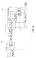
- FIG. 16 is a block diagram showing functions of an angiographic apparatus in the medical image processing system according to the second embodiment
- FIG. 17 is a block diagram showing functions of the angiographic apparatus in the medical image processing system according to the second embodiment
- FIG. 19 is a block diagram showing functions of an angiographic apparatus in the medical image processing system according to the third embodiment.
- FIG. 21 is a diagram showing an example of an alarm display
- FIG. 24 is a schematic diagram showing an example of a structure of a medical image processing system according to a fifth embodiment
- FIG. 25 is a block diagram showing functions of a medical image processing apparatus in the medical image processing system according to the fifth embodiment.
- FIG. 26 is a schematic diagram showing an example of a structure of a medical image processing system according to a sixth embodiment
- FIG. 27 is a block diagram showing functions of a medical image processing apparatus in the medical image processing system according to the sixth embodiment.
- FIG. 28 is a block diagram showing functions of the medical image processing apparatus in the medical image processing system according to the sixth embodiment.
- FIG. 30 is a schematic diagram showing an example of a structure of a medical image processing system according to a seventh embodiment
- FIG. 31 is a block diagram showing functions of a medical image processing apparatus in the medical image processing system according to the seventh embodiment.
- FIG. 32 is a block diagram showing functions of the medical image processing apparatus in the medical image processing system according to the seventh embodiment.
- the present embodiments provide the medical image processing system including: an angiographic image acquisition unit configured to acquire an angiographic image on a region including a blood vessel; a volume data generation unit configured to three-dimensionally reconstruct the angiographic image to generate volume data; a vessel extraction unit configured to extract blood vessels on the basis of the volume data; a sorting unit configured to sort collateral circulations and ischemic blood vessels on the basis of the blood vessels; and an image synthesis unit configured to apply different image processes to the collateral circulations and the ischemic blood vessels, and to generate a synthesized image.
- images with visible vessel structures can be generated.
- FIG. 1 is a schematic diagram showing an example of a structure of a medical image processing system according to a first embodiment.
- FIG. 1 shows a medical image processing system 1 according to the first embodiment.
- the medical image processing system 1 includes an angiographic apparatus 10 as an X-ray image diagnostic apparatus.
- the angiographic apparatus 10 is mainly constituted of a supporting device 11 and a DF (digital fluorography) device 12 .
- the supporting device 11 includes an X-ray tube 21 , an X-ray detector 22 , a C-arm 23 , a table-top (catheter table) 25 , a high-voltage generator 26 , a drive mechanism 27 , and an automatic contrast agent injector (injector) 28 .
- an X-ray tube 21 X-ray detector 22
- C-arm 23 C-arm 23
- table-top (catheter table) 25 a high-voltage generator 26
- a drive mechanism 27 a drive mechanism 27
- an automatic contrast agent injector (injector) 28 a description will be given of the supporting device 11 of an under-tube-type in which the X-ray tube 21 is positioned below the table-top 25
- the supporting device 11 may be of an over-tube-type in which the X-ray tube 21 is positioned above the table-top 25 .
- an X-ray irradiation field diaphragm that is composed of a plurality of lead blades, and a compensating filer that is formed of silicon rubber or the like for attenuating a specified amount of an irradiated X-ray so as to prevent halation.
- the X-ray tube 21 which is provided in one end of the C-arm 23 , receives high voltage power from the high-voltage generator 26 and irradiates an object (patient) P with an X-ray in response to conditions of the high voltage power.
- the X-ray detector 22 is provided in another end of the C-arm 23 , which is an emission side of the X-ray tube 21 , to detect an X-ray which has transmitted through the patient P.
- the X-ray detector 22 is an I.I. (image intensifier)-TV system, and mainly includes an I.I. 22 a and a TV camera 22 b .
- the X-ray detector 22 may also be embodied by an FPD (flat panel detector).
- the I.I. 22 a converts the X-ray that has transmitted through the patient P, into visible light, and further multiplies luminance in process of light-electron-light conversion to form highly sensitive projection data.
- the TV camera 22 b converts optical projection data into electrical signals with use of a CCD (charge coupled device) image sensor.
- CCD charge coupled device
- the C-arm 23 supports the X-ray tube 21 at one end and the X-ray detector 22 at the other end so that the X-ray tube 21 and the X-ray detector 22 are placed face to face about the patient P.
- a moving amount, movement timing, and a moving speed of the C-arm 23 are controlled by the drive mechanism 27 .
- the high-voltage generator 26 generates high voltage power to the X-ray tube 21 under a control of the DF device 12 .
- the drive mechanism 27 moves the C-arm 23 so as to draw an circular arc (in an LAO (left anterior oblique view) direction and in an RAO (right anterior oblique view) direction) or rotates the C-arm 23 (in a CRA (cranial view) direction and a CAU (caudal view) direction).
- the drive mechanism 27 also moves the C-arm 23 in parallel with a longitudinal direction of the table-top 25 that holds the patient P or stands and reclines the C-arm 23 integrally with the table-top 25 under the control of the DF device 12 .
- the drive mechanism 27 further moves the C-arm 23 straight in the longitudinal direction of the table-top 25 that holds the patient P under the control of the DF device 12 , so that the X-ray tube 21 and the X-ray detector 22 are moved in the longitudinal direction of the table-top 25 that holds the patient P for imaging.
- the drive mechanism 27 moves the table-top 25 in a vertical direction, a horizontal direction, and a longitudinal direction under the control of the DF device 12 .
- the injector 28 is an apparatus for injecting a contrast agent into a contrast agent catheter (not shown) that has inserted into an involved part of the patient P under the control of the DF device 12 .
- the DF device 12 which is structured by a computer as a base, can mutually communicate with a network N such as a hospital-based LAN (local area network).
- the DF device 12 is mainly constituted of hardware devices such as an A/D (analog to digital) conversion circuit 30 , an image generation circuit 31 , an image memory 32 , a display device 34 , a CPU (central processing unit) 35 as a processor, a comprehensive memory 36 , an HDD (hard disc drive) 37 , an input device 38 , a communication controller 39 , and a system controller 40 .
- the CPU 35 is mutually connected with respective hardware components that constitute the DF device 12 via a bus as a common signal transmission line.
- the DF device 12 may include a recording medium drive (not shown).
- the A/D conversion circuit 30 converts time-series analog signals (video signals) outputted from the X-ray detector 22 into digital signals.
- the image generation circuit 31 Under a control of the CPU 35 , the image generation circuit 31 applies logarithmic conversion processing (LOG processing) to digital signals of projection data outputted from the A/D conversion circuit 30 , applies addition processing thereto, where necessary, to generate frame-based image data, and stores the image data in the image memory 32 .
- the image generation circuit 31 also applies image processing to the frame-based image data, and stores the image data after image processing in the image memory 32 . Examples of the image processing include magnification, gradation, spatial filtering of the image data, tracing of minimum-value/maximum-value of sequentially stored image data, and addition processing for noise removal.
- the image data generated by the image generation circuit 31 is outputted to the CPU 35 and is stored in a storage device such as the image memory 32 .
- the image memory 32 stores the image data outputted from the image generation circuit 31 under the control of the CPU 35 .
- the CPU 35 is a controller having a packaged integrated circuit (LSI) structure in which an electronic circuit made of semiconductors has a plurality of terminals.
- LSI packaged integrated circuit
- the CPU 35 executes a program stored in the comprehensive memory 36 .
- the CPU 35 loads to the comprehensive memory 36 a program stored in the HDD 37 , a program transferred from the network N, received in the communication controller 39 and installed in the HDD 37 , or a program read from a recording medium mounted on a recording media drive (not shown) and installed in the HDD 37 .
- the CPU 35 then executes the loaded program.
- the comprehensive memory 36 includes ROM (read only memory), RAM (random access memory) or the like.
- the comprehensive memory 36 is a storage device that stores an IPL (initial program loading), a BIOS (BASIC input/output system) and data, and is also used for temporary storage of work memory and data of the CPU 35 .
- the HDD 37 is a storage device structured to unremovably incorporate a metal disk in which magnetic substances are applied or vapor-deposited thereto.
- the HDD 37 stores programs (including application programs and OS (operating system)) installed in the DF device 12 and data. It is also possible to provide GUIs (graphical user interfaces) which allow for heavy use of graphics to display information to users and allow for basic operations to be performed by the input device 38 to OS.
- GUIs graphical user interfaces
- the input device 38 includes such components as a keyboard and a mouse operable by an operator. Input signals in response to the operation are sent to the CPU 35 .
- the input device 38 is mainly constituted of a main console and a system console.
- the communication controller 39 performs communication control in conformity to each protocol.
- the communication controller 39 has a function allowing connection to the network N.
- the angiographic apparatus 10 can be connected to the network N through the communication controller 39 .
- the system controller 40 includes a not shown CPU and memory devices.
- the system controller 40 controls operation of the high voltage generator 26 , the drive mechanism 27 and the injector 28 in the supporting device 11 according to instructions from the CPU 35 .
- the angiographic image acquisition unit 51 has a function to acquire data of angiographic images (including non-contrast enhanced MRA images obtained without a contrast agent) collected by medical diagnostic imaging apparatuses such as X-ray CT apparatuses, MRI apparatuses and contrast-enhanced X-ray image diagnostic apparatuses via a storage device such as the HDD 37 or the network N, and the communication controller 39 .
- medical diagnostic imaging apparatuses such as X-ray CT apparatuses, MRI apparatuses and contrast-enhanced X-ray image diagnostic apparatuses
- CT image An example of an angiographic image (CT image) is shown in FIG. 4 .
- the volume data generation unit 52 has a function to three-dimensionally reconstruct an angiographic image acquired by the angiographic image acquisition unit 51 to generate volume data for three-dimensional image processing.
- the cerebral blood vessel extraction unit 53 has a function to extract data on cerebral blood vessels from the volume data generated by the volume data generation unit 52 .
- An example of a rendering image of the cerebral blood vessels extracted by the cerebral blood vessel extraction unit 53 is shown in FIG. 5 .
- the first sorting unit 54 has a function to sort the cerebral blood vessels into collateral circulations, ischemic blood vessels, and normal blood vessels based on the cerebral blood vessels extracted by the cerebral blood vessel extraction unit 53 .
- the first sorting unit 54 has a first collateral circulation extraction unit 54 a , a first ischemic blood vessel extraction unit 54 b , and a first normal blood vessel extraction unit 54 c.
- the first collateral circulation extraction unit 54 a has a function to extract, from the entire cerebral blood vessels extracted by the cerebral blood vessel extraction unit 53 , data on collateral circulations as circulatory systems which, in the case of an occluded blood circulation in a main artery or a cardinal vein, act to maintain blood flow to an organization through a bypass formed by branching or side-branching and act to maintain return flow to the heart.
- An example of a rendering image of the collateral circulations extracted by the first collateral circulation extraction unit 54 a is shown in FIG. 6 .
- the first ischemic blood vessel extraction unit 54 b has a function to extract data on ischemic blood vessels, which are blood vessels having a lowered blood flow rate on a downstream side, based on the entire cerebral blood vessels extracted by the cerebral blood vessel extraction unit 53 and the collateral circulations extracted by the first collateral circulation extraction unit 54 a .
- An example of a rendering image of the ischemic blood vessels extracted by the first ischemic blood vessel extraction unit 54 b is shown in FIG. 7 .
- the angiographic imaging control unit 55 has a function to control, once a contrast agent catheter is inserted into the patient P, the high-voltage generator 26 , the injector 28 , and the drive mechanism 27 through the system controller 40 so as to perform angiography imaging which is to irradiate a head of the patient P with an X-ray, a dosage of which is based on determined imaging conditions, and a function to acquire a contrast-enhanced X-ray image (projection image) generated by the image generation circuit 31 .
- An example of the contrast-enhanced X-ray image acquired by the angiography imaging control unit 55 is shown in FIG. 9 .
- the raysum fluoroscopic image generation unit 56 has a function to apply perspective projection (perspective) and raysum rendering (raysum rendering) processes to the volume data generated by the volume data generation unit 52 to generate raysum fluoroscopic image data.
- the alignment processing unit 57 has a function to align the raysum fluoroscopic image generated by the raysum fluoroscopic image generation unit 56 and the contrast-enhanced X-ray image sequentially acquired by the angiographic imaging control unit 55 generally in real time.
- the alignment by the alignment processing unit 57 is not limited to that with use of the raysum fluoroscopic image and the contrast-enhanced X-ray image.
- the alignment processing unit 57 may employ a method which uses image-attached information such as an imaging position and range attached to the data.
- the second sorting unit 58 has a function to sort respective blood vessels from the contrast-enhanced X-ray image aligned by the alignment processing unit 57 shown in FIG. 2 , based on the collateral circulations in the volume data extracted by the first collateral circulation extraction unit 54 a shown in FIG. 2 , the ischemic blood vessels in the volume data extracted by the first ischemic blood vessel extraction unit 54 b shown in FIG. 2 , and the normal blood vessels in the volume data extracted by the first normal blood vessel extraction unit 54 c shown in FIG. 2 .
- the second sorting unit 58 has a second collateral circulation extraction unit 58 a , a second ischemic blood vessel extraction unit 58 b , and a second normal blood vessel extraction unit 58 c.
- the second collateral circulation extraction unit 58 a has a function to extract collateral circulation data from the contrast-enhanced X-ray image aligned by the alignment processing unit 57 shown in FIG. 2 , based on the collateral circulations in the volume data extracted by the first collateral circulation extraction unit 54 a shown in FIG. 2 .
- An example of an image of the collateral circulations extracted by the second collateral circulation extraction unit 58 a is shown in FIG. 10 .
- the second ischemic blood vessel extraction unit 58 b has a function to extract ischemic blood vessel data from the contrast-enhanced X-ray image aligned by the alignment processing unit 57 shown in FIG. 2 , based on the ischemic blood vessels in the volume data extracted by the first ischemic blood vessel extraction unit 54 b shown in FIG. 2 .
- An example of an image of the ischemic blood vessels extracted by the second ischemic blood vessel extraction unit 58 b is shown in FIG. 11 .
- the second normal blood vessel extraction unit 58 c has a function to extract normal blood vessel data from the contrast-enhanced X-ray image aligned by the alignment processing unit 57 shown in FIG. 2 , based on the normal blood vessels in the volume data extracted by the first normal blood vessel extraction unit 54 c shown in FIG. 2 .
- An example of an image of the normal blood vessels extracted by the second normal blood vessel extraction unit 58 c is shown in FIG. 12 .
- the filter unit 59 has a suppression filter unit 59 a and a highlight filter unit 59 b .
- the suppression filter unit 59 a of the filter unit 59 performs processing to suppress display of the collateral circulations, while the highlight filter unit 59 b performs processing to highlight the ischemic blood vessels.
- the suppression filter unit 59 a of the filter unit 59 performs display suppression of the ischemic blood vessels, while the highlight filter unit 59 b performs processing to highlight the collateral circulations.
- the suppression filter unit 59 a has a function to apply a suppression filter to suppress display of the collateral circulations in the contrast-enhanced X-ray image. This function is used in the case where collateral circulations in the contrast-enhanced X-ray image extracted by the second collateral circulation extraction unit 58 a have abnormally developed vessel structures and ischemic blood vessels are a highlighted target. An example of an image of the collateral circulations subjected to the suppression filter by the suppression filter unit 59 a is shown in FIG. 13 .
- the highlight filter unit 59 b has a function to apply a highlight filter to highlight display of ischemic blood vessels in the contrast-enhanced X-ray image. This function is used in the case where ischemic blood vessels in the contrast-enhanced X-ray image extracted by the second ischemic blood vessel extraction unit 58 b have normal vessel structures and ischemic blood vessels are a highlighted target.
- the image synthesis unit 60 has a function to apply different image processes to the collateral circulations filtered by the suppression filter unit 59 a , the ischemic blood vessels filtered by the highlight filter unit 59 b , and the normal blood vessels extracted by the second normal blood vessel extraction unit 58 c , to perform synthesis processing thereof, and to sequentially generate synthesized image data.
- the image synthesis unit 60 is set so that the filtered collateral circulations, ischemic blood vessels and the normal blood vessels have independent display attributes (such as display/non-display status, color, and transparency), and then sequentially generates synthesized image data.
- the synthesized image also includes synthesized text information and scales of various parameters or the like.
- the synthesized image generated by the image synthesis unit 60 is sent to the display device 34 as video signals and is displayed through the display device 34 .
- the synthesized image is displayed generally in real time by the image synthesis unit 60 as a reproduced moving image.
- FIG. 14 is a diagram showing contrast-enhanced X-ray images according to the conventional technology in an upper row and showing an example of the synthesized images according to the first embodiment in a lower row.
- the contrast-enhanced X-ray images and the synthesized images shown in FIG. 14 are arrayed in a time-series order from the left-hand side to the right-hand side.
- a contrast agent inflow area spreads out with elapse of time in the contrast-enhanced X-ray images according to the conventional technology. Since collateral circulations, ischemic blood vessels, and normal blood vessels are not sorted, the collateral circulations, the ischemic blood vessels, and the normal blood vessels are displayed with an identical display attribute.
- a contrast agent inflow area also spreads out with elapse of time in the synthesized image of the first embodiment.
- the lower row of FIG. 14 shows an example in which collateral circulations, ischemic blood vessels, and normal blood vessels are displayed with an identical display attribute for the sake of convenience, it is also possible to display the collateral circulations, the ischemic blood vessels, and the normal blood vessels with different display attributes.
- cerebral blood vessels in a contrast-enhanced X-ray image are sorted into collateral circulations and ischemic blood vessels, the respective blood vessels are subjected to different image processes and filtering, and the respective blood vessels are then displayed with independent display attributes, so that vessel structures are reproduced and displayed in real time as visible images.
- a second embodiment is different from the first embodiment in the point that collateral circulations and ischemic blood vessels are displayed with a rendering image of volume data by being synthesized therewith.
- FIG. 15 is a schematic diagram showing an example of a structure of a medical image processing system according to the second embodiment.
- FIG. 15 shows a medical image processing system 1 A according to the second embodiment.
- the medical image processing system 1 A includes an angiographic apparatus 10 A as an X-ray image diagnostic apparatus.
- the angiographic apparatus 10 A is mainly constituted of a supporting device 11 and a DF device 12 A.
- the DF device 12 A which is structured by a computer as a base, can mutually communicate with a network N such as a hospital-based LAN.
- the DF device 12 A is mainly constituted of hardware devices such as an A/D conversion circuit 30 , an image generation circuit 31 , an image memory 32 , a display device 34 , a CPU 35 A as a processor, a comprehensive memory 36 , an HDD 37 , an input device 38 , a communication controller 39 , and a system controller 40 .
- the CPU 35 A is mutually connected with respective hardware components that constitute the DF device 12 A via a bus as a common signal transmission line.
- the DF device 12 A may include a recording medium drive (not shown).
- FIGS. 16 and 17 are block diagrams showing functions of the angiographic apparatus 10 A in the medical image processing system 1 A according to the second embodiment.
- the angiographic apparatus 10 A functions as an angiographic image acquisition unit 51 , a volume data generation unit 52 , a cerebral blood vessel extraction unit 53 , a first sorting unit 54 , an angiographic imaging control unit 55 , a raysum fluoroscopic image generation unit 56 , an alignment processing unit 57 , a second sorting unit 58 , a filter unit 59 , and an image synthesis unit 60 A.
- each of the component members 51 through 60 A shown in FIGS. 16 and 17 is described as functions of the CPU 35 A, the present invention is not limited thereto.
- Each of the component members 51 through 60 A may be a hardware device included in the angiographic apparatus 10 A.
- the image synthesis unit 60 A has a function to synthesize a rendering (including MPR) image based on volume data generated by the volume data generation unit 52 shown in FIG. 16 , collateral circulations filtered by a suppression filter unit 59 a , ischemic blood vessels filtered by a highlight filter unit 59 b , and normal blood vessels extracted by a second normal blood vessel extraction unit 58 c , to provide a setting so that each blood vessel has an independent display attribute, and to sequentially generate synthesized image data.
- the synthesized image also includes synthesized text information and scales of various parameters or the like.
- the synthesized image generated by the image synthesis unit 60 A is sent to the display device 34 as video signals and is displayed through the display device 34 .
- the synthesized image is displayed generally in real time by the image synthesis unit 60 A as a reproduced moving image.
- the synthesized image generated by the image synthesis unit 60 A can be used as a load map for use at the time of inserting a treatment catheter.
- cerebral blood vessels in a contrast-enhanced X-ray image are sorted into collateral circulations and ischemic blood vessels, the respective blood vessels are subjected to different image processes and filtering, and the respective blood vessels are then displayed with independent display attributes, so that vessel structures are reproduced and displayed in real time as visible images at the time of the catheter treatment with the angiographic apparatus 10 A.
- FIG. 18 is a schematic diagram showing one example of a structure of a medical image processing system according to the third embodiment.
- FIG. 18 shows a medical image processing system 1 B according to the third embodiment.
- the medical image processing system 1 B includes an angiographic apparatus 10 B as an X-ray image diagnostic apparatus.
- the angiographic apparatus 10 B is mainly constituted of a supporting device 11 and a DF device 12 B.
- the DF device 12 B which is structured by a computer as a base, can mutually communicate with a network N such as a hospital-based LAN.
- the DF device 12 B is mainly constituted of hardware devices such as an A/D conversion circuit 30 , an image generation circuit 31 , an image memory 32 , a display device 34 , a CPU 35 B as a processor, a comprehensive memory 36 , an HDD 37 , an input device 38 , a communication controller 39 , and a system controller 40 .
- the CPU 35 B is mutually connected with respective hardware components that constitute the DF device 12 B via a bus as a common signal transmission line.
- the DF device 12 B may include a recording medium drive (not shown).
- FIGS. 19 and 20 are block diagrams showing functions of the angiographic apparatus 10 B in the medical image processing system 1 B according to the third embodiment.
- the angiographic apparatus 10 B functions as an angiographic image acquisition unit 51 , a volume data generation unit 52 , a cerebral blood vessel extraction unit 53 , a first sorting unit 54 , an angiographic imaging control unit 55 , a raysum fluoroscopic image generation unit 56 , an alignment processing unit 57 , a second sorting unit 58 , a filter unit 59 , an image synthesis unit 60 B, a catheter tip position acquisition unit 61 , a concerned area setting unit 62 , a fluoroscopic control unit 63 , and an alarm determination unit 64 .
- each of the component members 51 through 64 shown in FIGS. 19 and 20 is described as functions of the CPU 35 B, the present invention is not limited thereto.
- Each of the component members 51 through 64 may be a hardware device included in the angiographic apparatus 10 B.
- the concerned area setting unit 62 has a function to set a concerned area on a synthesized image generated by the image synthesis unit 60 B. For example, when it is desired to avoid insertion of a treatment catheter into collateral circulations, the concerned area setting unit 62 sets a collateral circulation selected by an operator as a concerned area on the synthesized image displayed through the display device 34 .
- the image synthesis unit 60 B has a function to synthesize the above-mentioned synthesized image and a fluoroscopic image sequentially acquired by the fluoroscopic control unit 63 to generate a fluoroscopic synthesized image in sequence.
- the fluoroscopic synthesized image also includes synthesized text information and scales of various parameters or the like.
- the fluoroscopic synthesized image generated by the image synthesis unit 60 B is sent to the display device 34 as video signals and is displayed through the display device 34 .
- the fluoroscopic synthesized image is displayed generally in real time by the image synthesis unit 60 B as a reproduced moving image.
- the above-mentioned synthesized image and the serial fluoroscopic image may independently be displayed side by side through the display device 34 without being synthesized with each other.
- FIG. 21 is a diagram showing an example of an alarm display.
- the alarm determination unit 64 detects the tip of the treatment catheter and issues an alarm through the display device 34 .
- An alarming method is not limited to the method shown in FIG. 21 .
- the display attributes of the collateral circulation as a concerned area may be changed (blinked or the like) to inform an operator of the alarm.
- the medical image processing system 1 B urges a user to change a moving direction of the treatment catheter when a distance between the concerned area and the tip of the treatment catheter is decreased during fluoroscopic guidance.
- the concerned area setting unit 62 may set the collateral circulation as a concerned area, and then the image synthesis unit 60 B may guide the treatment catheter in a direction toward the concerned area.
- cerebral blood vessels in a contrast-enhanced X-ray image are sorted into collateral circulations and ischemic blood vessels, the respective blood vessels are subjected to different image processes and filtering, and the respective blood vessels are displayed with independent display attributes, so that vessel structures are reproduced and displayed in real time as visible images at the time of the catheter treatment by the angiographic apparatus 10 B.
- the image synthesis unit 60 C has a function to synthesize collateral circulations in the volume data extracted by a first collateral circulation extraction unit 54 a , ischemic blood vessels in the volume data extracted by a first ischemic blood vessel extraction unit 54 b , and normal blood vessels extracted by a first normal blood vessel extraction unit 54 c , to provide a setting so that each blood vessel has an independent display attribute and to perform rendering with the setting so as to generate synthesized image data.
- the synthesized image also includes synthesized text information and scales of various parameters or the like.
- the synthesized image generated by the image synthesis unit 60 C is sent to the display device 34 as video signals and is displayed through the display device 34 .
- an object of a fifth embodiment is to perform post-imaging processing of a diagnostic imaging workstation or the like as in the forth embodiment, the fifth embodiment does not have functions to collect and process images in real time.
- FIG. 24 is a schematic diagram showing one example of a structure of a medical image processing system according to the fifth embodiment.
- FIG. 24 shows a medical image processing system 1 D according to the fifth embodiment.
- the medical image processing system 1 D includes a medical image processing apparatus 70 D.
- the medical image processing apparatus 70 D which is structured by a computer as a base, can mutually communicate with a network N.
- the medical image processing apparatus 70 D is mainly constituted of basic hardware devices such as a display device 34 , a CPU 35 D, a comprehensive memory 36 , an HDD 37 , an input device 38 , and a communication controller 39 .
- the CPU 35 D is mutually connected with respective hardware components that constitute the medical image processing apparatus 70 D via a bus as a common signal transmission line.
- the medical image processing apparatus 70 D may include a storage medium drive (not shown).
- FIG. 25 is a block diagram showing functions of the medical image processing apparatus 70 D in the medical image processing system 1 D according to the fifth embodiment.
- the medical image processing apparatus 70 D When the CPU 35 D shown in FIG. 24 executes a program, the medical image processing apparatus 70 D functions as an angiographic image acquisition unit 51 , a volume data generation unit 52 , a cerebral blood vessel extraction unit 53 , a first sorting unit 54 , an image synthesis unit 60 D, and a function image acquisition unit 81 as shown in FIG. 25 .
- the component members 51 through 54 , 60 D and 81 shown in FIG. 25 is described as functions of the CPU 35 D, the present invention is not limited thereto.
- Each of the component members 51 through 54 , 60 D and 81 may be a hardware device included in the medical image processing apparatus 70 D.
- the function image acquisition sections 81 has a function to acquire function images on a region including a brain collected by medical diagnostic imaging apparatuses such as X-ray CT apparatuses, MRI apparatuses and PET (positron emission tomography) apparatuses, or to acquire data on processed images such as perfusion images obtained by analyzing the function images by post-processing, via a storage device such as the HDD 37 or the network N, and the communication controller 39 .
- medical diagnostic imaging apparatuses such as X-ray CT apparatuses, MRI apparatuses and PET (positron emission tomography) apparatuses
- processed images such as perfusion images obtained by analyzing the function images by post-processing
- the image synthesis unit 60 D has a function to synthesize collateral circulations in the volume data extracted by a first collateral circulation extraction unit 54 a , ischemic blood vessels in the volume data extracted by a first ischemic blood vessel extraction unit 54 b , and normal blood vessels in the volume data extracted by a first normal blood vessel extraction unit 54 c , to provide a setting so that each blood vessel has an independent display attribute, to perform rendering, and to further synthesize the function image acquired by the function image acquisition unit 81 to generate synthesized image data.
- the synthesized image also includes synthesized text information and scales of various parameters or the like.
- the synthesized image generated by the image synthesis unit 60 D is sent to the display device 34 as video signals and is displayed through the display device 34 .
- the synthesized image generated by the image synthesis unit 60 D can present a relative positional relation between the function image, the collateral circulations and the ischemic blood vessels.
- cerebral blood vessels in a contrast-enhanced X-ray image are sorted into collateral circulations and ischemic blood vessels, and each vessel is displayed with an independent display attribute, so that vessel structures can be displayed as a visible image.
- an object of a sixth embodiment is to perform post-imaging processing of a diagnostic imaging workstation or the like as in the fourth and fifth embodiments, the sixth embodiment does not have functions to collect and process images in real time.
- FIG. 26 is a schematic diagram showing one example of a structure of a medical image processing system according to the sixth embodiment.
- FIG. 26 shows a medical image processing system 1 E according to the sixth embodiment.
- the medical image processing system 1 E shows a medical image processing apparatus 70 E.
- the medical image processing apparatus 70 E which is structured by a computer as a base, can mutually communicate with a network N.
- the medical image processing apparatus 70 E is mainly constituted of basic hardware devices such as a display device 34 , a CPU 35 E, a comprehensive memory 36 , an HDD 37 , an input device 38 , and a communication controller 39 .
- the CPU 35 E is mutually connected with respective hardware components that constitute the medical image processing apparatus 70 E via a bus as a common signal transmission line.
- the medical image processing apparatus 70 E may include a storage medium drive (not shown).
- FIGS. 27 and 28 are block diagrams showing functions of the medical image processing apparatus 70 E in the medical image processing system 1 E according to the sixth embodiment.
- the medical image processing apparatus 70 E functions, as shown in FIGS. 27 and 28 , as a first angiographic image acquisition section (angiographic image acquisition section) 51 , a first volume data generation section (volume data generation section) 52 , a first cerebral blood vessel extraction section (cerebral blood vessel extraction section) 53 , a first collateral circulation extraction unit 54 a , a first ischemic blood vessel extraction unit 54 b , an image synthesis unit 60 E, a third angiographic image acquisition unit 82 , a third volume data generation unit 83 , a third cerebral blood vessel extraction unit 84 , a third collateral circulation extraction unit 85 , a third ischemic blood vessel extraction unit 86 , a collateral circulation evaluation unit 87 , an ischemic blood vessel evaluation unit 88 , and a treatment effect determination unit 89 .
- each of the component members 51 through 54 b , 60 E and 82 through 89 shown in FIGS. 27 and 28 is described as functions of the CPU 35 E, the present invention is not limited thereto.
- Each of the component members 51 through 54 b , 60 E and 82 through 89 may be a hardware device included in the medical image processing apparatus 70 E.
- the first angiographic image acquisition unit 51 has a function to acquire angiographic images that are pre-treatment data.
- the third angiographic image acquisition unit 82 has a function to acquire post-treatment data that is data on angiographic images (including non-contrast enhanced MRA images obtained without a contrast agent) collected by medical diagnostic imaging apparatuses such as X-ray CT apparatuses, MRI apparatuses and contrast-enhanced X-ray image diagnostic apparatuses via a storage device such as the HDD 37 or the network N, and the communication controller 39 .
- medical diagnostic imaging apparatuses such as X-ray CT apparatuses, MRI apparatuses and contrast-enhanced X-ray image diagnostic apparatuses
- a storage device such as the HDD 37 or the network N, and the communication controller 39 .
- the third volume data generation unit 83 has a function to three-dimensionally reconstruct an angiographic image acquired by the third angiographic image acquisition unit 82 and to generate volume data for three-dimensional image processing.
- the third collateral circulation extraction unit 85 has a function to extract collateral circulations from the entire cerebral blood vessels extracted by the third cerebral blood vessel extraction unit 84 .
- the third collateral circulation extraction unit 85 extracts a collateral circulation as a region having a highest existence probability based on comparison with Atlas, estimation with feature values, or estimation with a morphological filter.
- the ischemic blood vessel evaluation unit 88 has a function to evaluate the level of recovery by treatment, based on the ischemic blood vessels extracted by the first ischemic blood vessel extraction unit 54 b shown in FIG. 27 and the ischemic blood vessels extracted by the third ischemic blood vessel extraction unit 86 .
- the ischemic blood vessel evaluation unit 88 calculates, for example, a time-series volume expansion rate of an ischemic blood vessel and evaluates (quantifies) the level of recovery by treatment.
- the treatment effect determination unit 89 has a function to determine whether or not a recovery speed of moyamoya disease is favorable based on the volume shrinkage rate of the collateral circulation by the collateral circulation evaluation unit 87 and the volume expansion rate of the ischemic blood vessel by the ischemic blood vessel evaluation unit 88 so as to determine a treatment effect against moyamoya disease.
- the level of recovery by the treatment evaluated by the collateral circulation evaluation unit 87 is quantitatively displayed (“40% volume decreased”).
- the level of recovery by the treatment evaluated by the ischemic blood vessel evaluation unit 88 is quantitatively displayed (“20% volume increased”), and the level of recovery of ischemia is quantitatively displayed (“contrast average 10% increased”).
- an object of a seventh embodiment is to perform post-imaging processing of a diagnostic imaging workstation or the like as in the fourth through sixth embodiments, the seventh embodiment does not have functions to collect and process images in real time.
- the seventh embodiment is applied to, for example, a direct bypass operation (superficial temporal artery-middle cerebral artery anastomosis) against moyamoya disease.
- the direct bypass operation is an anastomosis operation between an arteria cerebri media traveling on a cerebral surface and a superficial temporal artery that mainly supplies nutrition to skins and subcutaneous tissues of a head.
- FIG. 30 is a schematic diagram showing one example of a structure of a medical image processing system according to the seventh embodiment.
- FIG. 30 shows a medical image processing system 1 F according to the seventh embodiment.
- the medical image processing system 1 F includes a medical image processing apparatus 70 F.
- the medical image processing apparatus 70 F which is structured by a computer as a base, can mutually communicate with a network N.
- the medical image processing apparatus 70 F is mainly constituted of basic hardware devices such as a display device 34 , a CPU 35 F, a comprehensive memory 36 , an HDD 37 , an input device 38 , and a communication controller 39 .
- the CPU 35 F is mutually connected with respective hardware components that constitute the medical image processing apparatus 70 F via a bus as a common signal transmission line.
- the medical image processing apparatus 70 F may include a storage medium drive (not shown).
- FIGS. 31 and 32 are block diagrams showing functions of the medical image processing apparatus 70 F in the medical image processing system 1 F according to the seventh embodiment.
- the medical image processing apparatus 70 F functions, as shown in FIGS. 31 and 32 , as an angiographic image acquisition unit 51 , a volume data generation unit 52 , a cerebral blood vessel extraction unit 53 , a first collateral circulation extraction unit 54 a , a first ischemic blood vessel extraction unit 54 b , an image synthesis unit 60 F, a junction point coordinate setting unit 90 , a blood vessel branch coordinate setting unit 91 , a connecting distance calculation unit 92 , a bypass blood vessel blood flow rate calculation unit 93 , an ischemic blood vessel blood flow rate estimation unit 94 , and a bypass operation adequacy determination unit 95 .
- each of the component members 51 through 54 b , 60 F and 90 through 95 shown in FIGS. 31 and 32 is described as functions of the CPU 35 F, the present invention is not limited thereto.
- Each of the component members 51 through 54 b , 60 F and 90 through 95 may be a hardware device included in the medical image processing apparatus 70 F.
- the junction point coordinate setting unit 90 has a function to set a bypass position as a junction point coordinate (three-dimensional coordinate system) on an arteria cerebri media regarded as an ischemic blood vessel extracted by the first ischemic blood vessel extraction unit 54 b shown in FIG. 31 .
- the junction point coordinate setting unit 90 sets a junction point coordinate on the arteria cerebri media based on the junction point coordinate selected by an operator with use of the input device 38 .
- the blood vessel branch coordinate setting unit 91 has a function to set a bypass blood vessel branch as a blood vessel branch coordinate (three-dimensional coordinate system) on a superficial temporal artery, based on volume data generated by the volume data generation unit 52 shown in FIG. 31 .
- the blood vessel branch coordinate setting unit 91 sets a blood vessel branch coordinate on a superficial temporal artery based on the blood vessel branch coordinate selected by the operator with use of the input device 38 .
- the connecting distance calculation unit 92 has a function to calculate a distance required for connection between a junction point coordinate and a blood vessel branch coordinate based on the junction point coordinate set by the junction point coordinate setting unit 90 and the blood vessel branch coordinate set by the blood vessel branch coordinate setting unit 91 .
- the bypass blood vessel blood flow rate calculation unit 93 has a function to calculate a blood flow rate of a bypass superficial temporal artery before bypass treatment, based on the blood vessel branch coordinate set by the blood vessel branch coordinate setting unit 91 .
- the blood flow rate calculated by the bypass blood vessel blood flow rate calculation unit 93 is calculated based on time-series changes in a signal value of a cerebral blood vessel on a taken image.
- the ischemic blood vessel blood flow rate estimation unit 94 has a function to estimate a blood flow rate of the arteria cerebri media that is regarded as an ischemic blood vessel before bypass treatment, based on the blood flow rate of the bypass superficial temporal artery calculated by the bypass blood vessel blood flow rate calculation unit 93 and the junction point coordinate set by the junction point coordinate setting unit 90 .
- the bypass operation adequacy determination unit 95 has a function to estimate a blood flow rate of the arteria cerebri media after bypass treatment, based on a blood flow rate of the arteria cerebri media regarded as an ischemic blood vessel before bypass treatment, the blood flow rate being estimated by the ischemic blood vessel blood flow rate estimation unit 94 and based on a connecting distance calculated by the connecting distance calculation unit 92 , and to simulate whether or not ischemia can sufficiently be ameliorated.
- the bypass operation adequacy determination unit 95 determines, based on threshold processing or the like, whether or not a selected bypass superficial temporal artery is adequate for treatment.
- the image synthesis unit 60 F has a function to synthesize a rendering image of the volume data generated by the volume data generation unit 52 shown in FIG. 31 and a result of determination regarding adequacy of the direct bypass operation made by the bypass operation adequacy determination unit 95 to generate synthesized image data.
- the synthesized image also includes synthesized text information and scales of various parameters or the like.
- the synthesized image generated by the image synthesis unit 60 F is sent to the display device 34 as video signals and is displayed through the display device 34 .
- cerebral blood vessels in a contrast-enhanced X-ray image are sorted into collateral circulations and ischemic blood vessels, and each vessel is displayed with an independent display attribute, so that vessel structures can be displayed as a visible image.
- cerebral blood vessels in a contrast-enhanced X-ray image are sorted into collateral circulations and ischemic blood vessels, so that adequacy evaluation of the direct bypass operation can accurately be performed.
- the brain of the patient P has been described as a target region for easy understanding.
- the present invention is not limited to the example where the brain of the patient P is a target region.
Abstract
Description
Claims (13)
Applications Claiming Priority (3)
| Application Number | Priority Date | Filing Date | Title |
|---|---|---|---|
| JP2011228076A JP5921132B2 (en) | 2011-10-17 | 2011-10-17 | Medical image processing system |
| JP2011-228076 | 2011-10-17 | ||
| PCT/JP2012/075684 WO2013058114A1 (en) | 2011-10-17 | 2012-10-03 | Medical image processing system |
Related Parent Applications (1)
| Application Number | Title | Priority Date | Filing Date |
|---|---|---|---|
| PCT/JP2012/075684 Continuation WO2013058114A1 (en) | 2011-10-17 | 2012-10-03 | Medical image processing system |
Publications (2)
| Publication Number | Publication Date |
|---|---|
| US20130259336A1 US20130259336A1 (en) | 2013-10-03 |
| US9192347B2 true US9192347B2 (en) | 2015-11-24 |
Family
ID=48140766
Family Applications (1)
| Application Number | Title | Priority Date | Filing Date |
|---|---|---|---|
| US13/908,225 Active 2032-11-16 US9192347B2 (en) | 2011-10-17 | 2013-06-03 | Medical image processing system applying different filtering to collateral circulation and ischemic blood vessels |
Country Status (4)
| Country | Link |
|---|---|
| US (1) | US9192347B2 (en) |
| JP (1) | JP5921132B2 (en) |
| CN (1) | CN103327899B (en) |
| WO (1) | WO2013058114A1 (en) |
Cited By (3)
| Publication number | Priority date | Publication date | Assignee | Title |
|---|---|---|---|---|
| US20170290544A1 (en) * | 2016-04-12 | 2017-10-12 | Toshiba Medical Systems Corporation | Medical image processing apparatus, medical image diagnosis apparatus and recording medium |
| JP2020018695A (en) * | 2018-08-02 | 2020-02-06 | キヤノンメディカルシステムズ株式会社 | Magnetic resonance imaging apparatus |
| US10568599B2 (en) * | 2014-09-09 | 2020-02-25 | General Electric Company | Multiple frame acquisition for exposure control in X-ray medical imagers |
Families Citing this family (20)
| Publication number | Priority date | Publication date | Assignee | Title |
|---|---|---|---|---|
| US9342876B2 (en) * | 2013-04-25 | 2016-05-17 | Battelle Energy Alliance, Llc | Methods, apparatuses, and computer-readable media for projectional morphological analysis of N-dimensional signals |
| JP6422671B2 (en) * | 2013-05-27 | 2018-11-14 | キヤノンメディカルシステムズ株式会社 | Image processing apparatus and image processing method |
| WO2014196732A1 (en) * | 2013-06-03 | 2014-12-11 | 사회복지법인 삼성생명공익재단 | Novel magnetic resonance image technique for imaging and evaluating collateral circulation |
| CN103908239B (en) * | 2014-03-06 | 2016-01-20 | 中国科学院苏州生物医学工程技术研究所 | Contactless imaging system and formation method thereof |
| CN104933756B (en) * | 2014-03-21 | 2018-03-30 | 北京冠生云医疗技术有限公司 | The construction method and system of three-dimensional coronary analysis model |
| WO2016030744A1 (en) * | 2014-08-29 | 2016-03-03 | 강원대학교산학협력단 | Method for determining patient-specific blood vessel information |
| US9582916B2 (en) | 2014-11-10 | 2017-02-28 | Siemens Healthcare Gmbh | Method and system for unsupervised cross-modal medical image synthesis |
| US9595120B2 (en) | 2015-04-27 | 2017-03-14 | Siemens Healthcare Gmbh | Method and system for medical image synthesis across image domain or modality using iterative sparse representation propagation |
| WO2017087821A2 (en) | 2015-11-18 | 2017-05-26 | Lightlab Imaging, Inc. | X-ray image feature detection and registration systems and methods |
| CN105877767A (en) * | 2016-03-31 | 2016-08-24 | 北京思创贯宇科技开发有限公司 | Coronary artery image angiography method and device |
| EP3378403A1 (en) * | 2017-03-20 | 2018-09-26 | Koninklijke Philips N.V. | Contrast injection imaging |
| US10482600B2 (en) | 2018-01-16 | 2019-11-19 | Siemens Healthcare Gmbh | Cross-domain image analysis and cross-domain image synthesis using deep image-to-image networks and adversarial networks |
| JP7334034B2 (en) * | 2018-10-22 | 2023-08-28 | キヤノンメディカルシステムズ株式会社 | Medical image processing device, X-ray diagnostic device and medical image processing program |
| CN109523500B (en) * | 2018-11-19 | 2020-07-31 | 复旦大学附属华山医院 | Bypass blood vessel determination method and system for intracranial and extracranial blood flow reconstruction |
| CN109523536B (en) * | 2018-11-19 | 2020-10-16 | 复旦大学附属华山医院 | Bypass blood vessel determination method and system for intracranial and extracranial blood flow reconstruction |
| JP7165600B2 (en) * | 2019-02-28 | 2022-11-04 | キヤノンメディカルシステムズ株式会社 | X-ray diagnostic equipment and medical information processing equipment |
| WO2020217758A1 (en) * | 2019-04-25 | 2020-10-29 | 富士フイルム株式会社 | Pseudo angiography image generation device, method, and program |
| CN111613120B (en) * | 2020-04-08 | 2023-03-14 | 宁波创导三维医疗科技有限公司 | Interventional operation radiography imaging effect simulation system |
| KR102289648B1 (en) * | 2021-02-03 | 2021-08-18 | 주식회사 휴런 | Ischemic stroke detection and classification method based on medical image, apparatus and system |
| JP2023176250A (en) * | 2022-05-31 | 2023-12-13 | 朝日インテック株式会社 | Surgical operation support device, surgical operation support method and computer program |
Citations (18)
| Publication number | Priority date | Publication date | Assignee | Title |
|---|---|---|---|---|
| JPH0556974A (en) | 1991-09-04 | 1993-03-09 | Toshiba Corp | Ultrasonic diagnosing device |
| US5602891A (en) | 1995-11-13 | 1997-02-11 | Beth Israel | Imaging apparatus and method with compensation for object motion |
| US20030181809A1 (en) | 2002-03-11 | 2003-09-25 | Hall Andrew F. | 3D imaging for catheter interventions by use of 2D/3D image fusion |
| US20050015006A1 (en) * | 2003-06-03 | 2005-01-20 | Matthias Mitschke | Method and apparatus for visualization of 2D/3D fused image data for catheter angiography |
| US20050046644A1 (en) * | 2003-08-28 | 2005-03-03 | Satoru Ohishi | 3D image processing apparatus |
| JP2006198060A (en) | 2005-01-19 | 2006-08-03 | Ziosoft Inc | Image processing method and image processing program |
| WO2007026598A1 (en) | 2005-08-31 | 2007-03-08 | Gifu University | Medical image processor and image processing method |
| US20080081980A1 (en) * | 2006-09-18 | 2008-04-03 | Michael Maschke | Apparatus and process for stroke examination and treatment using a C-arch X-ray system |
| JP2008206556A (en) | 2007-02-23 | 2008-09-11 | Hitachi Ltd | Medical image processing system |
| US20090010519A1 (en) * | 2007-07-05 | 2009-01-08 | Kabushiki Kaisha Toshiba | Medical image processing apparatus and medical image diagnosis apparatus |
| US20090129649A1 (en) * | 2007-11-20 | 2009-05-21 | Faycal Djeridane | Method and system for processing multiple series of biological images obtained from a patient |
| JP2009125582A (en) | 2007-11-21 | 2009-06-11 | Toshiba Corp | Magnetic resonance imaging apparatus |
| US20090328239A1 (en) * | 2006-07-31 | 2009-12-31 | Bio Tree Systems, Inc. | Blood vessel imaging and uses therefor |
| US20100002839A1 (en) * | 2008-07-04 | 2010-01-07 | Kabushiki Kaisha Toshiba | X-ray imaging apparatus that displays analysis image with taken image, x-ray imaging method, and image processing apparatus |
| US20100014727A1 (en) * | 2008-07-21 | 2010-01-21 | Shenzhen Institute Of Advanced Technology | Methods and devices for producing the parameters of the brain tissues and assessing data of the suitability for thrombolysis of a patient |
| US20110103657A1 (en) * | 2008-01-02 | 2011-05-05 | Bio-Tree Systems, Inc. | Methods of obtaining geometry from images |
| US20110103666A1 (en) | 2009-10-29 | 2011-05-05 | Kabushiki Kaisha Toshiba | X-ray imaging apparatus |
| US20120226141A1 (en) * | 2011-03-02 | 2012-09-06 | Toshiba Medical Systems Corporation | Magnetic resonance imaging apparatus and magnetic resonance imaging method |
-
2011
- 2011-10-17 JP JP2011228076A patent/JP5921132B2/en active Active
-
2012
- 2012-10-03 WO PCT/JP2012/075684 patent/WO2013058114A1/en active Application Filing
- 2012-10-03 CN CN201280005603.XA patent/CN103327899B/en active Active
-
2013
- 2013-06-03 US US13/908,225 patent/US9192347B2/en active Active
Patent Citations (22)
| Publication number | Priority date | Publication date | Assignee | Title |
|---|---|---|---|---|
| JPH0556974A (en) | 1991-09-04 | 1993-03-09 | Toshiba Corp | Ultrasonic diagnosing device |
| WO1997017673A1 (en) | 1995-11-10 | 1997-05-15 | Beth Israel Deaconess Medical Center | Imaging apparatus and method with compensation for object motion |
| JP2002515772A (en) | 1995-11-10 | 2002-05-28 | ベス・イスラエル・デイーコネス・メデイカル・センター | Imaging device and method for canceling movement of a subject |
| US5602891A (en) | 1995-11-13 | 1997-02-11 | Beth Israel | Imaging apparatus and method with compensation for object motion |
| US20030181809A1 (en) | 2002-03-11 | 2003-09-25 | Hall Andrew F. | 3D imaging for catheter interventions by use of 2D/3D image fusion |
| JP2003290192A (en) | 2002-03-11 | 2003-10-14 | Siemens Ag | Drawing method for image of medical instrument introduced into examination region of patient |
| US20050015006A1 (en) * | 2003-06-03 | 2005-01-20 | Matthias Mitschke | Method and apparatus for visualization of 2D/3D fused image data for catheter angiography |
| US20050046644A1 (en) * | 2003-08-28 | 2005-03-03 | Satoru Ohishi | 3D image processing apparatus |
| JP2006198060A (en) | 2005-01-19 | 2006-08-03 | Ziosoft Inc | Image processing method and image processing program |
| WO2007026598A1 (en) | 2005-08-31 | 2007-03-08 | Gifu University | Medical image processor and image processing method |
| US20090328239A1 (en) * | 2006-07-31 | 2009-12-31 | Bio Tree Systems, Inc. | Blood vessel imaging and uses therefor |
| US20080081980A1 (en) * | 2006-09-18 | 2008-04-03 | Michael Maschke | Apparatus and process for stroke examination and treatment using a C-arch X-ray system |
| JP2008206556A (en) | 2007-02-23 | 2008-09-11 | Hitachi Ltd | Medical image processing system |
| US20090010519A1 (en) * | 2007-07-05 | 2009-01-08 | Kabushiki Kaisha Toshiba | Medical image processing apparatus and medical image diagnosis apparatus |
| US20090129649A1 (en) * | 2007-11-20 | 2009-05-21 | Faycal Djeridane | Method and system for processing multiple series of biological images obtained from a patient |
| JP2009125582A (en) | 2007-11-21 | 2009-06-11 | Toshiba Corp | Magnetic resonance imaging apparatus |
| US20110103657A1 (en) * | 2008-01-02 | 2011-05-05 | Bio-Tree Systems, Inc. | Methods of obtaining geometry from images |
| US20100002839A1 (en) * | 2008-07-04 | 2010-01-07 | Kabushiki Kaisha Toshiba | X-ray imaging apparatus that displays analysis image with taken image, x-ray imaging method, and image processing apparatus |
| US20100014727A1 (en) * | 2008-07-21 | 2010-01-21 | Shenzhen Institute Of Advanced Technology | Methods and devices for producing the parameters of the brain tissues and assessing data of the suitability for thrombolysis of a patient |
| US20110103666A1 (en) | 2009-10-29 | 2011-05-05 | Kabushiki Kaisha Toshiba | X-ray imaging apparatus |
| JP2011115562A (en) | 2009-10-29 | 2011-06-16 | Toshiba Corp | X-ray equipment |
| US20120226141A1 (en) * | 2011-03-02 | 2012-09-06 | Toshiba Medical Systems Corporation | Magnetic resonance imaging apparatus and magnetic resonance imaging method |
Non-Patent Citations (5)
| Title |
|---|
| Higashino et al. Image Fusion of Coronary Tree and Regional Cardiac Function Image Using Multislice Computed Tomography, 2006, Circulation Journal, 70: 105-109. * |
| International Preliminary Report on Patentability and Written Opinion issued Apr. 22, 2014 in PCT/JP2012/075684 (submitting English translation only). |
| International Search Report issued on Nov. 6, 2012 for PCT/JP2012/075684 filed on Oct. 3, 2012 with English Translation. |
| International Written Opinion issued on Nov. 6, 2012 for PCT/JP2012/075684 filed on Oct. 3, 2012. |
| Office Action issued Aug. 18, 2015 in Japanese Patent Application No. 2011-228076. |
Cited By (5)
| Publication number | Priority date | Publication date | Assignee | Title |
|---|---|---|---|---|
| US10568599B2 (en) * | 2014-09-09 | 2020-02-25 | General Electric Company | Multiple frame acquisition for exposure control in X-ray medical imagers |
| US20170290544A1 (en) * | 2016-04-12 | 2017-10-12 | Toshiba Medical Systems Corporation | Medical image processing apparatus, medical image diagnosis apparatus and recording medium |
| US10537282B2 (en) * | 2016-04-12 | 2020-01-21 | Canon Medical Systems Corporation | Medical image processing apparatus, medical image diagnosis apparatus and recording medium |
| JP2020018695A (en) * | 2018-08-02 | 2020-02-06 | キヤノンメディカルシステムズ株式会社 | Magnetic resonance imaging apparatus |
| JP7177621B2 (en) | 2018-08-02 | 2022-11-24 | キヤノンメディカルシステムズ株式会社 | Magnetic resonance imaging system |
Also Published As
| Publication number | Publication date |
|---|---|
| JP2013085652A (en) | 2013-05-13 |
| CN103327899B (en) | 2016-04-06 |
| US20130259336A1 (en) | 2013-10-03 |
| WO2013058114A1 (en) | 2013-04-25 |
| JP5921132B2 (en) | 2016-05-24 |
| CN103327899A (en) | 2013-09-25 |
Similar Documents
| Publication | Publication Date | Title |
|---|---|---|
| US9192347B2 (en) | Medical image processing system applying different filtering to collateral circulation and ischemic blood vessels | |
| US8345823B2 (en) | X-ray image diagnosing apparatus, and controlling method of X-ray image diagnosing apparatus | |
| JP6108474B2 (en) | Medical imaging device for providing an image representation to assist in positioning an interventional device | |
| US8315355B2 (en) | Method for operating C-arm systems during repeated angiographic medical procedures | |
| JP6013012B2 (en) | Image processing apparatus and X-ray diagnostic apparatus | |
| JP5818491B2 (en) | Image processing apparatus and image processing method | |
| US8929633B2 (en) | Diagnostic X-ray system and method | |
| WO2012099222A1 (en) | X-ray diagnostic apparatus, image processing apparatus and image processing program | |
| JP2010154982A (en) | X-ray computer tomographic imaging apparatus and image processor | |
| JP2010213760A (en) | Image processing device, and image processing program | |
| WO2013157457A1 (en) | X-ray image capturing device, medical image processing device, x-ray image capturing method, and medical image processing method | |
| US11096640B2 (en) | X-ray diagnostic apparatus, image processing apparatus, and image processing method | |
| US10453184B2 (en) | Image processing apparatus and X-ray diagnosis apparatus | |
| US11464474B2 (en) | Medical image processing apparatus, X-ray diagnostic apparatus, and medical image processing method | |
| JP2007054147A (en) | Apparatus for assisting diagnostic imaging/treatment | |
| JP6744127B2 (en) | Medical image processor | |
| JP2019208903A (en) | Medical image processor, medical image processing method, medical image processing program | |
| KR101638597B1 (en) | Method and Apparatus for processing of medical images | |
| Fieselmann et al. | Automatic measurement of contrast bolus distribution in carotid arteries using a C-arm angiography system to support interventional perfusion imaging | |
| US20230309941A1 (en) | Medical image processing apparatus, x-ray diagnostic apparatus, and storage medium | |
| US20220230368A1 (en) | Method for the improvement of radiological images in the course of an angiography | |
| US10847262B2 (en) | Medical image processing apparatus, medical image processing method and medical image processing system | |
| US20240127450A1 (en) | Medical image processing apparatus and non-transitory computer readable medium | |
| Papanastasiou et al. | Comparison of distributed parameter and Fermi modeling of cardiac MR perfusion with CT perfusion in coronary artery disease versus invasive coronary angiography. |
Legal Events
| Date | Code | Title | Description |
|---|---|---|---|
| AS | Assignment |
Owner name: KABUSHIKI KAISHA TOSHIBA, JAPAN Free format text: ASSIGNMENT OF ASSIGNORS INTEREST;ASSIGNOR:WAKAI, SATOSHI;REEL/FRAME:030532/0983 Effective date: 20130521 Owner name: TOSHIBA MEDICAL SYSTEMS CORPORATION, JAPAN Free format text: ASSIGNMENT OF ASSIGNORS INTEREST;ASSIGNOR:WAKAI, SATOSHI;REEL/FRAME:030532/0983 Effective date: 20130521 |
|
| STCF | Information on status: patent grant |
Free format text: PATENTED CASE |
|
| AS | Assignment |
Owner name: TOSHIBA MEDICAL SYSTEMS CORPORATION, JAPAN Free format text: ASSIGNMENT OF ASSIGNORS INTEREST;ASSIGNOR:KABUSHIKI KAISHA TOSHIBA;REEL/FRAME:038891/0693 Effective date: 20160316 |
|
| MAFP | Maintenance fee payment |
Free format text: PAYMENT OF MAINTENANCE FEE, 4TH YEAR, LARGE ENTITY (ORIGINAL EVENT CODE: M1551); ENTITY STATUS OF PATENT OWNER: LARGE ENTITY Year of fee payment: 4 |
|
| MAFP | Maintenance fee payment |
Free format text: PAYMENT OF MAINTENANCE FEE, 8TH YEAR, LARGE ENTITY (ORIGINAL EVENT CODE: M1552); ENTITY STATUS OF PATENT OWNER: LARGE ENTITY Year of fee payment: 8 |