US9209654B2 - Method and apparatus for enhancing flame radiation - Google Patents
Method and apparatus for enhancing flame radiation Download PDFInfo
- Publication number
- US9209654B2 US9209654B2 US13/729,159 US201213729159A US9209654B2 US 9209654 B2 US9209654 B2 US 9209654B2 US 201213729159 A US201213729159 A US 201213729159A US 9209654 B2 US9209654 B2 US 9209654B2
- Authority
- US
- United States
- Prior art keywords
- flame
- hydrocarbon
- radiating energy
- time
- energy
- Prior art date
- Legal status (The legal status is an assumption and is not a legal conclusion. Google has not performed a legal analysis and makes no representation as to the accuracy of the status listed.)
- Expired - Fee Related, expires
Links
- 238000000034 method Methods 0.000 title claims description 36
- 230000005855 radiation Effects 0.000 title abstract description 14
- 230000002708 enhancing effect Effects 0.000 title abstract description 3
- 230000001965 increasing effect Effects 0.000 claims abstract description 9
- 239000004215 Carbon black (E152) Substances 0.000 claims description 69
- 229930195733 hydrocarbon Natural products 0.000 claims description 69
- 150000002430 hydrocarbons Chemical class 0.000 claims description 69
- 239000004020 conductor Substances 0.000 claims description 58
- 239000000446 fuel Substances 0.000 claims description 38
- 239000007789 gas Substances 0.000 claims description 15
- 239000004071 soot Substances 0.000 claims description 11
- OKTJSMMVPCPJKN-UHFFFAOYSA-N Carbon Chemical compound [C] OKTJSMMVPCPJKN-UHFFFAOYSA-N 0.000 claims description 10
- 229910052799 carbon Inorganic materials 0.000 claims description 10
- 230000007704 transition Effects 0.000 claims description 9
- 238000004891 communication Methods 0.000 claims description 8
- 230000001939 inductive effect Effects 0.000 claims description 8
- 238000002485 combustion reaction Methods 0.000 claims description 7
- 238000005054 agglomeration Methods 0.000 claims description 6
- 230000002776 aggregation Effects 0.000 claims description 6
- 230000015572 biosynthetic process Effects 0.000 claims description 5
- 238000006243 chemical reaction Methods 0.000 claims description 5
- 238000004146 energy storage Methods 0.000 claims description 5
- 239000002800 charge carrier Substances 0.000 claims description 4
- 125000004432 carbon atom Chemical group C* 0.000 claims description 3
- 239000007806 chemical reaction intermediate Substances 0.000 claims description 3
- 238000010438 heat treatment Methods 0.000 claims description 3
- 230000005457 Black-body radiation Effects 0.000 claims description 2
- 125000004429 atom Chemical group 0.000 claims description 2
- 239000007795 chemical reaction product Substances 0.000 claims description 2
- 238000009792 diffusion process Methods 0.000 claims description 2
- 239000012530 fluid Substances 0.000 claims description 2
- 150000002500 ions Chemical class 0.000 claims description 2
- 238000004519 manufacturing process Methods 0.000 claims description 2
- 239000000615 nonconductor Substances 0.000 claims description 2
- 239000007800 oxidant agent Substances 0.000 claims description 2
- 238000010248 power generation Methods 0.000 claims description 2
- QVGXLLKOCUKJST-UHFFFAOYSA-N atomic oxygen Chemical compound [O] QVGXLLKOCUKJST-UHFFFAOYSA-N 0.000 claims 1
- 229910052760 oxygen Inorganic materials 0.000 claims 1
- 239000001301 oxygen Substances 0.000 claims 1
- 238000010586 diagram Methods 0.000 description 7
- ATUOYWHBWRKTHZ-UHFFFAOYSA-N Propane Chemical compound CCC ATUOYWHBWRKTHZ-UHFFFAOYSA-N 0.000 description 6
- 229910000831 Steel Inorganic materials 0.000 description 6
- VNWKTOKETHGBQD-UHFFFAOYSA-N methane Chemical compound C VNWKTOKETHGBQD-UHFFFAOYSA-N 0.000 description 6
- 239000010959 steel Substances 0.000 description 6
- 238000012546 transfer Methods 0.000 description 6
- 238000013459 approach Methods 0.000 description 4
- 238000005516 engineering process Methods 0.000 description 4
- 230000000694 effects Effects 0.000 description 3
- 238000002474 experimental method Methods 0.000 description 3
- 239000003345 natural gas Substances 0.000 description 3
- 239000001294 propane Substances 0.000 description 3
- UGFAIRIUMAVXCW-UHFFFAOYSA-N Carbon monoxide Chemical compound [O+]#[C-] UGFAIRIUMAVXCW-UHFFFAOYSA-N 0.000 description 2
- 230000008901 benefit Effects 0.000 description 2
- 229910002091 carbon monoxide Inorganic materials 0.000 description 2
- 230000015556 catabolic process Effects 0.000 description 2
- 230000008859 change Effects 0.000 description 2
- 239000003245 coal Substances 0.000 description 2
- 230000000295 complement effect Effects 0.000 description 2
- 230000005684 electric field Effects 0.000 description 2
- 230000003993 interaction Effects 0.000 description 2
- 239000000543 intermediate Substances 0.000 description 2
- 238000002955 isolation Methods 0.000 description 2
- 230000007246 mechanism Effects 0.000 description 2
- OTMSDBZUPAUEDD-UHFFFAOYSA-N Ethane Chemical compound CC OTMSDBZUPAUEDD-UHFFFAOYSA-N 0.000 description 1
- 206010024769 Local reaction Diseases 0.000 description 1
- 239000011449 brick Substances 0.000 description 1
- 239000001273 butane Substances 0.000 description 1
- 239000012141 concentrate Substances 0.000 description 1
- 238000001816 cooling Methods 0.000 description 1
- -1 diesel Substances 0.000 description 1
- 230000003292 diminished effect Effects 0.000 description 1
- 239000000295 fuel oil Substances 0.000 description 1
- 239000003502 gasoline Substances 0.000 description 1
- 239000010763 heavy fuel oil Substances 0.000 description 1
- 238000009434 installation Methods 0.000 description 1
- 239000003915 liquefied petroleum gas Substances 0.000 description 1
- 239000007788 liquid Substances 0.000 description 1
- 238000002156 mixing Methods 0.000 description 1
- 239000000203 mixture Substances 0.000 description 1
- IJDNQMDRQITEOD-UHFFFAOYSA-N n-butane Chemical compound CCCC IJDNQMDRQITEOD-UHFFFAOYSA-N 0.000 description 1
- OFBQJSOFQDEBGM-UHFFFAOYSA-N n-pentane Natural products CCCCC OFBQJSOFQDEBGM-UHFFFAOYSA-N 0.000 description 1
- 239000002245 particle Substances 0.000 description 1
- 230000000737 periodic effect Effects 0.000 description 1
- 238000001556 precipitation Methods 0.000 description 1
- 230000008569 process Effects 0.000 description 1
- 239000000376 reactant Substances 0.000 description 1
- 238000006479 redox reaction Methods 0.000 description 1
- 230000002441 reversible effect Effects 0.000 description 1
- 230000002459 sustained effect Effects 0.000 description 1
- 238000012360 testing method Methods 0.000 description 1
- 238000011144 upstream manufacturing Methods 0.000 description 1
- 230000000007 visual effect Effects 0.000 description 1
Images


Classifications
-
- H02J17/00—
-
- F—MECHANICAL ENGINEERING; LIGHTING; HEATING; WEAPONS; BLASTING
- F23—COMBUSTION APPARATUS; COMBUSTION PROCESSES
- F23C—METHODS OR APPARATUS FOR COMBUSTION USING FLUID FUEL OR SOLID FUEL SUSPENDED IN A CARRIER GAS OR AIR
- F23C99/00—Subject-matter not provided for in other groups of this subclass
- F23C99/001—Applying electric means or magnetism to combustion
-
- F—MECHANICAL ENGINEERING; LIGHTING; HEATING; WEAPONS; BLASTING
- F23—COMBUSTION APPARATUS; COMBUSTION PROCESSES
- F23D—BURNERS
- F23D14/00—Burners for combustion of a gas, e.g. of a gas stored under pressure as a liquid
-
- F—MECHANICAL ENGINEERING; LIGHTING; HEATING; WEAPONS; BLASTING
- F23—COMBUSTION APPARATUS; COMBUSTION PROCESSES
- F23D—BURNERS
- F23D14/00—Burners for combustion of a gas, e.g. of a gas stored under pressure as a liquid
- F23D14/12—Radiant burners
- F23D14/151—Radiant burners with radiation intensifying means other than screens or perforated plates
-
- F—MECHANICAL ENGINEERING; LIGHTING; HEATING; WEAPONS; BLASTING
- F23—COMBUSTION APPARATUS; COMBUSTION PROCESSES
- F23G—CREMATION FURNACES; CONSUMING WASTE PRODUCTS BY COMBUSTION
- F23G2202/00—Combustion
- F23G2202/70—Combustion with application of specific energy
- F23G2202/701—Electrical fields
-
- H—ELECTRICITY
- H02—GENERATION; CONVERSION OR DISTRIBUTION OF ELECTRIC POWER
- H02J—CIRCUIT ARRANGEMENTS OR SYSTEMS FOR SUPPLYING OR DISTRIBUTING ELECTRIC POWER; SYSTEMS FOR STORING ELECTRIC ENERGY
- H02J50/00—Circuit arrangements or systems for wireless supply or distribution of electric power
- H02J50/05—Circuit arrangements or systems for wireless supply or distribution of electric power using capacitive coupling
-
- H—ELECTRICITY
- H02—GENERATION; CONVERSION OR DISTRIBUTION OF ELECTRIC POWER
- H02J—CIRCUIT ARRANGEMENTS OR SYSTEMS FOR SUPPLYING OR DISTRIBUTING ELECTRIC POWER; SYSTEMS FOR STORING ELECTRIC ENERGY
- H02J50/00—Circuit arrangements or systems for wireless supply or distribution of electric power
- H02J50/10—Circuit arrangements or systems for wireless supply or distribution of electric power using inductive coupling
Definitions
- Fuels with a relatively high C/H atomic ratio e.g., heavy fuel oils and coal, may be used to produce relatively high emissivity flames.
- these fuels are also prone to higher particulate and carbon monoxide (CO) emissions.
- Cleaner burning fuels such as natural gas exhibit relatively poor heat transfer via thermal radiation owing to low emissivity of their flames.
- a system for radiating energy from a flame may include a flame charging system configured to receive a time-varying voltage and impart a corresponding time-varying charge or voltage onto the flame.
- the flame charging system may have at least intermittent contact with the flame, and may be embodied as a portion of a fuel nozzle, flame holder, or discrete electrode past which the flame is directed, may include an ion-ejecting electrode, or may include an ionizer.
- An electrically isolated conductor may be located proximate the flame. The electrically isolated conductor may be arranged to be in electromagnetic communication with the time-varying charge imparted onto the flame, and may be configured to interact with the time-varying charge of the flame to increase radiated thermal energy.
- a method for radiating energy from a hydrocarbon flame may include providing a hydrocarbon fuel, igniting the hydrocarbon fuel to produce a flame, energizing the flame with a time-varying voltage or charge, and supporting an isolated electrical conductor adjacent to the flame to cause the flame to emit enhanced visible or infrared light energy.
- the electrically isolated conductor may be arranged to be in electromagnetic communication with the time-varying voltage or charge imparted onto the flame to cause the increased radiated thermal energy.
- FIG. 1 is a diagram illustrating a system for radiating energy from a flame, according to an embodiment.
- FIG. 2 is a diagram illustrating the system of FIG. 1 in relation to a system including a heat transfer surface, according to an embodiment.
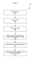
- FIG. 3 is a flow chart showing a method for increasing radiation from a flame, according to an embodiment.
- FIG. 4 is a diagram illustrating a theory explaining the behavior of the methods and systems described in conjunction with FIGS. 1-3 , according to an embodiment.
- FIG. 1 is a diagram illustrating a system 101 for radiating energy from a flame 102 , according to an embodiment.
- a flame charging system 104 may be configured to receive a time-varying voltage and impart a corresponding time-varying charge or voltage onto a hydrocarbon flame 102 .
- An electrically isolated conductor 106 proximate the flame 102 was found to interact with the time-varying charge of the flame 102 to cause the flame 102 to change in appearance from being substantially transparent to being bright yellow. It was concluded that the electrically isolated conductor 106 may be arranged to be in electrical communication with the time-varying charge imparted onto the hydrocarbon flame 102 . The change in flame appearance was believed to correspond to an increase in emissivity of heated species within the flame.
- the flame charging system 104 may include a flame energization electrode having at least intermittent contact with the flame 102 .
- the flame charging system 104 may be configured to receive a time-varying voltage selected to cause the flame energization electrode to impart the corresponding time-varying electrical charge or voltage onto the flame.
- An energization electrode may operate by conduction of voltage from the energization electrode to the flame.
- the flame charging system may include a charge-ejecting electrode disposed proximate to the flame.
- the charge-ejecting electrode may be configured to receive a time-varying voltage and to eject a corresponding time-varying electrical charge toward the flame.
- the charge-ejecting electrode may be referred to as a corona electrode.
- the charge-ejecting electrode may include a sharp electrode.
- the flame charging system may include an ionizer configured to receive a time-varying voltage and provide a fluid medium carrying corresponding time-varying electrical charge or voltage to or in proximity to the flame.
- the ionizer may be configured to impart the time-varying electrical charges onto a fuel.
- the ionizer may be configured to impart the time-varying electrical charges onto combustion air.
- the ionizer may be configured to impart the time-varying electrical charges onto one or more types of charge carriers and to deliver the one or more types of charge carriers to the combustion reaction.
- a phase-varying electrical energy interchange between the time-varying charge of the flame 102 and the electrically isolated conductor 106 may correspond to an increase in the formation of carbon molecules or carbon agglomerations in the flame 102 .
- the carbon molecules or carbon agglomerations in the flame may incandesce and increase the emissivity of the flame. No increase in soot output from the flame 102 was seen.
- the resultant increase in radiation from the flame 102 may be used to increase radiation heat transfer to an apparatus or workpiece.
- the system 101 may further include a flame holder 108 configured to anchor the flame 102 .
- the flame holder 108 may be electrically isolated or an electrical insulator.
- a fuel source 110 such as a hydrocarbon gas fuel source including a nozzle or hole 112 may be configured to stream the hydrocarbon gas past the flame holder 108 .
- the hydrocarbon gas fuel source may include an electrically insulating pipe or hose 114 configured to electrically isolate the nozzle or hole 112 from a relative ground.
- a time-varying voltage source 116 may provide a modulated voltage to the flame charging system 104 .
- the time-varying voltage source 116 may include a microcontroller, field-programmable gate array (FPGA), application specific integrated circuit (ASIC), state machine, integrated circuits, and/or discrete circuitry to output a waveform.
- the time-varying voltage source 116 may further be configured to select the waveform responsive to open-loop logic and/or feedback from a sensor circuit (not shown).
- the time-varying voltage source 116 may further include an amplifier configured to receive the waveform and output the time-varying voltage.
- the flame charging system may include a flame energization electrode 104 arranged to be in substantially continuous contact with the flame 102 when the flame 102 is burning.
- the time varying voltage and a geometry of the flame energization electrode 104 may be selected to substantially prevent formation of an electrical arc.
- the time-varying voltage may be selected to cause a phase-varying electrical energy interchange between the flame 102 and the electrically isolated conductor 106 .
- the electrically isolated conductor 106 may be arranged in a capacitive relationship with the time-varying charge imparted onto the flame.
- the time-varying voltage may be selected to cause a phase-varying capacitive energy storage between the flame 102 and the electrically isolated conductor 106 .
- the electrically isolated conductor 106 may be arranged in an inductive relationship with the time-varying charge imparted onto the flame 102 .
- the time-varying voltage may be selected to cause a phase-varying inductive energy storage or a combined inductive-capacitive energy storage between the flame 102 and the electrically isolated conductor 106 .
- the time-varying voltage may be selected to cause a phase-varying local transition state concentration and/or charge balance in the flame.
- the phase-varying electrical energy interchange or phase-varying local transition state concentration and/or charge balance may correspond to a decrease in an average flame temperature.
- the decrease in average flame temperature may be viewed as an outcome of a time-varying rate of reaction and/or as an outcome of radiating more energy from the flame 102 .
- the electrically isolated conductor 106 was found to operate as described when configured as a steel ring.
- the electrically isolated conductor may include a ring or ring segment at least partially surrounding the flame.
- the electrically isolated conductor 106 may be arranged to be substantially coaxial to the flame.
- the electrically isolated conductor 106 was found to operate as described when it was in substantially continuous physical contact with the flame. According to another embodiment, the electrically isolated conductor 106 may occasionally or intermittently come into physical contact with the flame. “Physical contact” may be defined as visual contact with a flame edge.
- An arrangement corresponding to 101 was operated using a hydrocarbon gas flame 102 produced by combustion of propane.
- Other fuels may alternatively or additionally be burned and/or other reduction-oxidation reactions may be supported to operate as described.
- the hydrocarbon may include greater than or fewer than three carbon atoms.
- Other illustrative hydrocarbon fuels may include natural gas, ethane, butane, liquefied petroleum gases, refinery gas or liquid mixtures, gasoline, diesel, fuel oil, coal, etc.
- FIG. 2 is a diagram illustrating the system 101 of FIG. 1 in relationship to a system 201 including a heat transfer surface 202 , according to an embodiment.
- embodiments may include a surface 202 configured to receive radiant energy from the flame 102 .
- the surface 202 may comprise a portion of an industrial process 201 configured to receive radiant energy from the flame 102 , a heating system 201 configured to receive radiant energy from the flame 102 , an electrical power generation system 201 configured to receive radiant energy from the flame 102 , a land vehicle, watercraft, or aircraft including an apparatus 201 configured to receive radiant energy from the flame 102 , and/or a structure (not shown) configured to hold a workpiece 202 to receive radiant energy from the flame 102 .
- FIG. 3 is a flow chart showing a method 301 for increasing radiation from a flame, according to an embodiment.
- a fuel may be provided.
- providing a fuel may include providing a hydrocarbon fuel.
- a hydrocarbon fuel may have one to three carbon atoms per molecule, or may have more atoms per molecule.
- various embodiments may include increasing radiation output of flames produced by combusting other fuels, low molecular weight hydrocarbon gas fuels are illustratively addressed because such fuels typically produce flames that are substantially transparent, owing to low emissivity of the gas and the reaction intermediates, and thus may particularly benefit from methods described herein.
- the method 301 may be used to increase thermal radiation from a natural gas flame.
- the hydrocarbon fuel may be ignited to produce a flame.
- the method 301 may include premixing air or other oxidizer and the fuel (not shown).
- the flame may include or be a diffusion flame.
- the flame may be energized with a time-varying voltage or electrical charge.
- Energizing the flame with a time-varying voltage or electrical charge may include driving a first electrode near or at least partially in the flame with a corresponding time varying voltage.
- energizing the flame with a time-varying voltage or electrical charge may include driving a fuel nozzle or a flame holder with a corresponding time varying voltage.
- energizing the flame with a time-varying voltage or electrical charge may include driving an ionizer with the time-varying voltage to create the corresponding time-varying electrical charge.
- energizing the flame with a time-varying voltage or electrical charge may include driving an ion-ejecting electrode with the time-varying voltage to eject ions corresponding time-varying voltage or electrical charge toward or onto the flame.
- energizing the flame with a time-varying voltage may include energizing the flame with a periodically-varying voltage at 50 to 10,000 hertz frequency.
- the flame may be energized with a periodically-varying voltage at a 50-1000 hertz frequency. It was noted during experiments that a 400 hertz frequency resulted in a larger amount of radiated energy than did a 50 hertz frequency, other parameters being equal.
- Waveforms may similarly be varied.
- energizing the flame with a time-varying voltage may include energizing the flame with a square wave, sawtooth wave, sine wave or other waveform. It was noted during experiments that a square wave resulted in a larger shift to radiated energy than did a sinusoidal waveform, other parameters being equal.
- energizing the flame with a time-varying voltage may include energizing the flame with a 1000 volt to 115,000 volt amplitude.
- the voltage may be between 8000 to 40,000 volt amplitude. It is believed that larger flames may respond favorably to larger voltages.
- Step 306 may further include providing a flame energization geometry or control circuitry to substantially prevent arcing.
- the flame energization voltage may be alternated or applied in such a way as to not exceed the breakdown voltage of the ambient environment or the flame. Exceeding the breakdown voltage will produce an electrical spark in a phenomenon known as arcing.
- One approach for reducing arcing may be to smooth all edges of the first electrode to avoid charge concentrations that may tend to initiate an arc.
- Another approach may be to control voltage with sufficient accuracy to avoid voltage spikes that may initiate an arc.
- Another approach may be to use a feedback circuit in combination with a current limiting power supply to cut power upon sensing arcing or incipient arcing conditions.
- an electrical conductor may be supported adjacent to the gas flame to cause the flame to emit enhanced visible and/or infrared light energy.
- An example electrical conductor 106 may be seen in FIG. 1 .
- the electrical conductor may, for example, be in electrical continuity with ground through a resistance greater than about one mega-ohm and/or may be insulated or isolated from ground. Use of a high resistance to ground and/or isolation of the electrical conductor may allow the electrical conductor to electrically float.
- the electrical conductor may be in capacitive communication with the energized flame.
- the electrical conductor may be in inductive communication with the energized flame.
- the flame emission behavior described herein may involve a periodic energy exchange between capacitance and/or inductance and thermal energy of the flame.
- the electrical conductor may operate in combination with the modulated, time-varying charge on the flame to reduce the concentration of a transition state due to removal of one sign of charge during one half-cycle, and then act as a source of some or all of the sign of charge and local reaction transition state concentration during the subsequent half-cycle.
- soot is electrically conductive and soot particles can concentrate electrical fields
- an external electrical field may increase the precipitation of soot from a flame. Ionic mechanisms of soot formation have been postulated in the literature, but no mention of external fields has been previously suggested.
- the time-varying voltage may be selected to cause an increase in an incandescing soot fraction of the flame.
- the electrical conductor may include a ring surrounding an upper portion of the flame and not in contact with the flame.
- the flame may emit enhanced visible and/or infrared light energy, shown as step 310 .
- interactions between the charge on the flame and the conductor may cause the flame to emit enhanced visible or infrared light energy responsive increasing the emissivity of reaction products and reaction intermediates in the flame.
- increasing radiation from the flame may include shifting a reaction path to at least temporarily produce soot.
- the soot may emit black body radiation corresponding to the flame temperature.
- At least a portion of the radiated energy may be transmitted at to an apparatus.
- FIG. 4 is a diagram 401 illustrating a theory explaining the behavior of the methods and systems described in conjunction with FIGS. 1-3 , according to an illustrative embodiment.
- voltage, V is plotted as a function of time, t.
- a first voltage waveform 402 shown as a solid line approximating a sine wave, may correspond to a time-varying voltage applied to the first electrode described above.
- phase-shifted waveform 404 shown as a dashed line.
- the voltage of the conductor 404 may follow.
- the voltage applied to the flame 402 may lower than the voltage 404 responsively held by the conductor.
- electrons may be attracted out of at least portions of the flame toward the conductor.
- positively charged species may be attracted from proximity to the conductor to the flame. Because the charge to mass ratio of electrons is so much larger than the charge to mass ratio of positive species present in the flame, the movement of electrons may be responsible for most or substantially all of the effects described herein. The effect of the attraction of electrons out of the flame may be viewed in several ways. Remaining positive charges may unbalance the local population of transition states (excited molecules and intermediates) or charges.
- the positive charge imbalance may tend to be associated with carbon molecules or agglomerations, which hold heat produced during the previous half-cycle, and emit the heat as radiation.
- some of the energy of the system may be temporarily converted to a capacitive and/or inductive energy held in a field between the flame and the conductor.
- the voltage applied to the flame 402 may be higher than the voltage 404 responsively held by the conductor.
- electrons may be attracted from proximity to the conductor and into the flame.
- the concentration of transition states and/or the charge balance the combustion reaction may again be satisfied, causing carbon molecules or agglomerations to be consumed.
- energy may be extracted from a capacitive and/or inductive energy field to be expressed as heat energy in the flame.
- a propane gas flame continued to burn substantially transparently when a voltage was applied to the energization electrode 104 .
- an experimental apparatus 101 included an ungrounded 6 inches steel pipe flange as the conductor 106 .
- the pipe flange 106 was supported by refractory bricks concentric to and at a height of 8 inches above the bottom edge of the energization electrode 104 .
- the energization electrode 104 was again energized according to the parameters given above.
- the apparatus 101 produced a much yellower and surging flame.
- the brightness of the light output was greater when the energization electrode 104 was driven with a square wave at 1000 Hz than a square wave driven at the same voltage at 50 Hz.
- the gap between the top of the energization electrode 104 and the bottom of the ring 106 was 41 ⁇ 4′′ axially. Adding a second ring 106 on top of the first ring 106 gave no noticeable increase in brightness. If anything, adding a second ring diminished the brightness somewhat.
- Blue tendrils were noted between the hole 112 and the flame holder 108 when a voltage waveform was applied to the energization electrode 104 in the presence of the ring 106 . No blue tendrils were seen when voltage was applied in the absence of the ring 106 . Electrical isolation of the pipe 110 from ground was measured. Some leakage to ground was found, but very little.
- the apparatus of EXAMPLE 2 was modified by grounding the ring 106 . Upon application of the energization voltage, a very brief increase in flame luminosity was noted. The flame did not exhibit any sustained increase in luminosity.
Landscapes
- Engineering & Computer Science (AREA)
- Chemical & Material Sciences (AREA)
- Combustion & Propulsion (AREA)
- Mechanical Engineering (AREA)
- General Engineering & Computer Science (AREA)
- Photometry And Measurement Of Optical Pulse Characteristics (AREA)
Abstract
Description
-
- Energization Electrode 104:
- A 3-inch nominal diameter steel pipe was cut to a length of 3¾ inches. The
energization electrode 104 was positioned about 16 inches above a 0.775-inch diameter hole 112. - Conductor 106:
- Absent.
- Fuel Source 110:
- A 0.775-
inch diameter hole 112 was formed in a threaded ¾-inch steel pipe end. The threaded steel end was mounted on piece of ¾-inch steel pipe about 8 inches in length. Anon-conductive hose 114 was secured to an upstream end of thefuel pipe 110. Propane was supplied at a pressure of about 8 PSIG.
-
- A time-varying voltage was applied as a square wave at a frequency of 50-1000 Hz. An indicated voltage of 2-8V was indicated by a National Instruments PXI-5412 waveform generator mounted in a National Instruments NI PXIe-1062Q chassis. The waveform was amplified 4000× by a TREK Model 40/15 high voltage amplifier to produce a time-varying relative driving voltage range of 8000 V to 32000 V at the
energization electrode 104.
- A time-varying voltage was applied as a square wave at a frequency of 50-1000 Hz. An indicated voltage of 2-8V was indicated by a National Instruments PXI-5412 waveform generator mounted in a National Instruments NI PXIe-1062Q chassis. The waveform was amplified 4000× by a TREK Model 40/15 high voltage amplifier to produce a time-varying relative driving voltage range of 8000 V to 32000 V at the
Claims (63)
Priority Applications (2)
| Application Number | Priority Date | Filing Date | Title |
|---|---|---|---|
| US13/729,159 US9209654B2 (en) | 2011-12-30 | 2012-12-28 | Method and apparatus for enhancing flame radiation |
| US14/930,372 US20160123576A1 (en) | 2011-12-30 | 2015-11-02 | Method and apparatus for enhancing flame radiation in a coal-burner retrofit |
Applications Claiming Priority (2)
| Application Number | Priority Date | Filing Date | Title |
|---|---|---|---|
| US201161582239P | 2011-12-30 | 2011-12-30 | |
| US13/729,159 US9209654B2 (en) | 2011-12-30 | 2012-12-28 | Method and apparatus for enhancing flame radiation |
Related Child Applications (1)
| Application Number | Title | Priority Date | Filing Date |
|---|---|---|---|
| US14/930,372 Continuation-In-Part US20160123576A1 (en) | 2011-12-30 | 2015-11-02 | Method and apparatus for enhancing flame radiation in a coal-burner retrofit |
Publications (2)
| Publication Number | Publication Date |
|---|---|
| US20130170090A1 US20130170090A1 (en) | 2013-07-04 |
| US9209654B2 true US9209654B2 (en) | 2015-12-08 |
Family
ID=48694623
Family Applications (1)
| Application Number | Title | Priority Date | Filing Date |
|---|---|---|---|
| US13/729,159 Expired - Fee Related US9209654B2 (en) | 2011-12-30 | 2012-12-28 | Method and apparatus for enhancing flame radiation |
Country Status (6)
| Country | Link |
|---|---|
| US (1) | US9209654B2 (en) |
| EP (1) | EP2798270A4 (en) |
| CN (1) | CN104136850B (en) |
| CA (1) | CA2860054A1 (en) |
| MX (1) | MX2014007905A (en) |
| WO (1) | WO2013102139A1 (en) |
Cited By (32)
| Publication number | Priority date | Publication date | Assignee | Title |
|---|---|---|---|---|
| US20130230810A1 (en) * | 2012-03-01 | 2013-09-05 | Clearsign Combustion Corporation | Inertial electrode and system configured for electrodynamic interaction with a flame |
| US9441834B2 (en) | 2012-12-28 | 2016-09-13 | Clearsign Combustion Corporation | Wirelessly powered electrodynamic combustion control system |
| US9468936B2 (en) | 2012-03-27 | 2016-10-18 | Clearsign Combustion Corporation | Electrically-driven particulate agglomeration in a combustion system |
| US9494317B2 (en) | 2012-09-10 | 2016-11-15 | Clearsign Combustion Corporation | Electrodynamic combustion control with current limiting electrical element |
| US20160363315A1 (en) * | 2013-12-31 | 2016-12-15 | Clearsign Combustion Corporation | Method and apparatus for extending flammability and stability limits in a combustion reaction |
| US20170146234A1 (en) * | 2014-07-30 | 2017-05-25 | Clearsign Combustion Corporation | Asymmetrical unipolar flame ionizer using a step-up transformer |
| US9696031B2 (en) | 2012-03-27 | 2017-07-04 | Clearsign Combustion Corporation | System and method for combustion of multiple fuels |
| US9739479B2 (en) | 2013-03-28 | 2017-08-22 | Clearsign Combustion Corporation | Battery-powered high-voltage converter circuit with electrical isolation and mechanism for charging the battery |
| US20170370587A1 (en) * | 2015-01-15 | 2017-12-28 | King Abdullah University Of Science And Technology | Systems and methods for controlling flame instability |
| US9909759B2 (en) | 2013-03-08 | 2018-03-06 | Clearsign Combustion Corporation | System for electrically-driven classification of combustion particles |
| US10006715B2 (en) | 2015-02-17 | 2018-06-26 | Clearsign Combustion Corporation | Tunnel burner including a perforated flame holder |
| US10047950B2 (en) | 2013-02-21 | 2018-08-14 | Clearsign Combustion Corporation | Oscillating combustor with pulsed charger |
| US10066835B2 (en) | 2013-11-08 | 2018-09-04 | Clearsign Combustion Corporation | Combustion system with flame location actuation |
| US10088151B2 (en) | 2011-02-09 | 2018-10-02 | Clearsign Combustion Corporation | Method for electrodynamically driving a charged gas or charged particles entrained in a gas |
| US10161625B2 (en) | 2013-07-30 | 2018-12-25 | Clearsign Combustion Corporation | Combustor having a nonmetallic body with external electrodes |
| US10174938B2 (en) | 2014-06-30 | 2019-01-08 | Clearsign Combustion Corporation | Low inertia power supply for applying voltage to an electrode coupled to a flame |
| US10190767B2 (en) | 2013-03-27 | 2019-01-29 | Clearsign Combustion Corporation | Electrically controlled combustion fluid flow |
| US10281141B2 (en) | 2014-10-15 | 2019-05-07 | Clearsign Combustion Corporation | System and method for applying an electric field to a flame with a current gated electrode |
| US10295185B2 (en) | 2013-10-14 | 2019-05-21 | Clearsign Combustion Corporation | Flame visualization control for electrodynamic combustion control |
| US10295175B2 (en) | 2013-09-13 | 2019-05-21 | Clearsign Combustion Corporation | Transient control of a combustion Reaction |
| US10359213B2 (en) | 2013-02-14 | 2019-07-23 | Clearsign Combustion Corporation | Method for low NOx fire tube boiler |
| US10364980B2 (en) | 2013-09-23 | 2019-07-30 | Clearsign Combustion Corporation | Control of combustion reaction physical extent |
| US10386062B2 (en) | 2013-02-14 | 2019-08-20 | Clearsign Combustion Corporation | Method for operating a combustion system including a perforated flame holder |
| US10422523B2 (en) | 2013-10-04 | 2019-09-24 | Clearsign Combustion Corporation | Ionizer for a combustion system |
| US10458647B2 (en) | 2014-08-15 | 2019-10-29 | Clearsign Combustion Corporation | Adaptor for providing electrical combustion control to a burner |
| US10514165B2 (en) | 2016-07-29 | 2019-12-24 | Clearsign Combustion Corporation | Perforated flame holder and system including protection from abrasive or corrosive fuel |
| US10619845B2 (en) | 2016-08-18 | 2020-04-14 | Clearsign Combustion Corporation | Cooled ceramic electrode supports |
| US10753605B2 (en) | 2012-05-31 | 2020-08-25 | Clearsign Technologies Corporation | Low NOx burner |
| US10808927B2 (en) | 2013-10-07 | 2020-10-20 | Clearsign Technologies Corporation | Pre-mixed fuel burner with perforated flame holder |
| US10823401B2 (en) | 2013-02-14 | 2020-11-03 | Clearsign Technologies Corporation | Burner system including a non-planar perforated flame holder |
| US11280255B2 (en) | 2019-06-25 | 2022-03-22 | Keith Bendle | Fossil fuel catalyzation system using negative charge to fuel injector in order to increase burn/combustion efficiency |
| US11460188B2 (en) | 2013-02-14 | 2022-10-04 | Clearsign Technologies Corporation | Ultra low emissions firetube boiler burner |
Families Citing this family (30)
| Publication number | Priority date | Publication date | Assignee | Title |
|---|---|---|---|---|
| US8851882B2 (en) * | 2009-04-03 | 2014-10-07 | Clearsign Combustion Corporation | System and apparatus for applying an electric field to a combustion volume |
| KR20120129907A (en) * | 2010-01-13 | 2012-11-28 | 클리어사인 컨버스천 코포레이션 | Method and apparatus for elecrical control of heat transfer |
| US11073280B2 (en) | 2010-04-01 | 2021-07-27 | Clearsign Technologies Corporation | Electrodynamic control in a burner system |
| US9732958B2 (en) | 2010-04-01 | 2017-08-15 | Clearsign Combustion Corporation | Electrodynamic control in a burner system |
| US9284886B2 (en) | 2011-12-30 | 2016-03-15 | Clearsign Combustion Corporation | Gas turbine with Coulombic thermal protection |
| CN104136850B (en) | 2011-12-30 | 2016-09-28 | 克利尔赛恩燃烧公司 | For the method and apparatus strengthening Fire Radiation |
| US9377195B2 (en) | 2012-03-01 | 2016-06-28 | Clearsign Combustion Corporation | Inertial electrode and system configured for electrodynamic interaction with a voltage-biased flame |
| US9267680B2 (en) | 2012-03-27 | 2016-02-23 | Clearsign Combustion Corporation | Multiple fuel combustion system and method |
| US9366427B2 (en) | 2012-03-27 | 2016-06-14 | Clearsign Combustion Corporation | Solid fuel burner with electrodynamic homogenization |
| US9702550B2 (en) | 2012-07-24 | 2017-07-11 | Clearsign Combustion Corporation | Electrically stabilized burner |
| US9310077B2 (en) | 2012-07-31 | 2016-04-12 | Clearsign Combustion Corporation | Acoustic control of an electrodynamic combustion system |
| US8911699B2 (en) | 2012-08-14 | 2014-12-16 | Clearsign Combustion Corporation | Charge-induced selective reduction of nitrogen |
| WO2014085696A1 (en) | 2012-11-27 | 2014-06-05 | Clearsign Combustion Corporation | Precombustion ionization |
| US9513006B2 (en) | 2012-11-27 | 2016-12-06 | Clearsign Combustion Corporation | Electrodynamic burner with a flame ionizer |
| US9746180B2 (en) | 2012-11-27 | 2017-08-29 | Clearsign Combustion Corporation | Multijet burner with charge interaction |
| US9562681B2 (en) | 2012-12-11 | 2017-02-07 | Clearsign Combustion Corporation | Burner having a cast dielectric electrode holder |
| US10677454B2 (en) | 2012-12-21 | 2020-06-09 | Clearsign Technologies Corporation | Electrical combustion control system including a complementary electrode pair |
| WO2014105990A1 (en) | 2012-12-26 | 2014-07-03 | Clearsign Combustion Corporation | Combustion system with a grid switching electrode |
| US9469819B2 (en) | 2013-01-16 | 2016-10-18 | Clearsign Combustion Corporation | Gasifier configured to electrodynamically agitate charged chemical species in a reaction region and related methods |
| US10364984B2 (en) * | 2013-01-30 | 2019-07-30 | Clearsign Combustion Corporation | Burner system including at least one coanda surface and electrodynamic control system, and related methods |
| CN107448943B (en) | 2013-02-14 | 2020-11-06 | 美一蓝技术公司 | Perforated flame holder and burner comprising a perforated flame holder |
| CN104903647B (en) | 2013-02-14 | 2018-02-02 | 克利尔赛恩燃烧公司 | Fuel combustion system with perforation stable reaction device |
| US10571124B2 (en) | 2013-02-14 | 2020-02-25 | Clearsign Combustion Corporation | Selectable dilution low NOx burner |
| US9696034B2 (en) | 2013-03-04 | 2017-07-04 | Clearsign Combustion Corporation | Combustion system including one or more flame anchoring electrodes and related methods |
| US9664386B2 (en) | 2013-03-05 | 2017-05-30 | Clearsign Combustion Corporation | Dynamic flame control |
| WO2014183135A1 (en) | 2013-05-10 | 2014-11-13 | Clearsign Combustion Corporation | Combustion system and method for electrically assisted start-up |
| WO2015017087A1 (en) | 2013-07-29 | 2015-02-05 | Clearsign Combustion Corporation | Combustion-powered electrodynamic combustion system |
| WO2015051136A1 (en) * | 2013-10-02 | 2015-04-09 | Clearsign Combustion Corporation | Electrical and thermal insulation for a combustion system |
| WO2016140681A1 (en) * | 2015-03-05 | 2016-09-09 | Clearsign Combustion Corporation | APPLICATION OF ELECTRIC FIELDS TO CONTROL CO AND NOx GENERATION IN A COMBUSTION REACTION |
| FR3084978B1 (en) * | 2018-08-10 | 2020-07-17 | Uwinloc | RADIO FREQUENCY ENERGY COLLECTION CIRCUIT AND COMMUNICATION DEVICE INCLUDING SUCH A RADIO FREQUENCY COLLECTION CIRCUIT |
Citations (64)
| Publication number | Priority date | Publication date | Assignee | Title |
|---|---|---|---|---|
| US1153182A (en) | 1912-12-19 | 1915-09-07 | Frederic W C Schniewind | Purification of coal. |
| US2604936A (en) | 1946-01-15 | 1952-07-29 | Metal Carbides Corp | Method and apparatus for controlling the generation and application of heat |
| US3087472A (en) | 1961-03-30 | 1963-04-30 | Asakawa Yukichi | Method and apparatus for the improved combustion of fuels |
| US3224485A (en) | 1963-05-06 | 1965-12-21 | Inter Probe | Heat control device and method |
| US3306338A (en) * | 1965-11-01 | 1967-02-28 | Exxon Research Engineering Co | Apparatus for the application of insulated a.c. fields to flares |
| US3358731A (en) | 1966-04-01 | 1967-12-19 | Mobil Oil Corp | Liquid fuel surface combustion process and apparatus |
| US3416870A (en) * | 1965-11-01 | 1968-12-17 | Exxon Research Engineering Co | Apparatus for the application of an a.c. electrostatic field to combustion flames |
| US3503348A (en) | 1968-08-30 | 1970-03-31 | Hagan Ind Inc | Incinerator |
| US3749545A (en) | 1971-11-24 | 1973-07-31 | Univ Ohio State | Apparatus and method for controlling liquid fuel sprays for combustion |
| US3841824A (en) | 1972-09-25 | 1974-10-15 | G Bethel | Combustion apparatus and process |
| US3869362A (en) | 1973-01-11 | 1975-03-04 | Ebara Mfg | Process for removing noxious gas pollutants from effluent gases by irradiation |
| US4052139A (en) | 1974-11-12 | 1977-10-04 | Pierre Paillaud | Method and apparatus for improving the energy yield of a reaction |
| US4091779A (en) | 1974-11-28 | 1978-05-30 | Daimler-Benz Aktiengesellschaft | Method and apparatus for influencing thermo-chemical reactions |
| US4093430A (en) | 1974-08-19 | 1978-06-06 | Air Pollution Systems, Incorporated | Apparatus for ionizing gases, electrostatically charging particles, and electrostatically charging particles or ionizing gases for removing contaminants from gas streams |
| US4111636A (en) | 1976-12-03 | 1978-09-05 | Lawrence P. Weinberger | Method and apparatus for reducing pollutant emissions while increasing efficiency of combustion |
| US4118202A (en) | 1977-10-17 | 1978-10-03 | Ball Corporation | Pre-primed fuel and method and apparatus for its manufacture |
| US4219001A (en) | 1976-09-30 | 1980-08-26 | Tokai Trw & Co. Ltd. | Method and apparatus for accumulating fuel particles in a portion of a combustion chamber |
| US4260394A (en) | 1979-08-08 | 1981-04-07 | Advanced Energy Dynamics, Inc. | Process for reducing the sulfur content of coal |
| US4291539A (en) | 1978-02-10 | 1981-09-29 | Monash University | Power generation system |
| US4304096A (en) | 1979-05-11 | 1981-12-08 | The Regents Of The University Of Minnesota | Method for reducing particulates discharged by combustion means |
| US4340024A (en) | 1978-10-13 | 1982-07-20 | Nissan Motor Company, Limited | Internal combustion engine |
| US4439980A (en) | 1981-11-16 | 1984-04-03 | The United States Of America As Represented By The Secretary Of The Navy | Electrohydrodynamic (EHD) control of fuel injection in gas turbines |
| US4649260A (en) | 1983-03-16 | 1987-03-10 | Coal-O-Matic Pvba | Lighter for stove, open hearth and similar |
| US4675029A (en) | 1984-11-21 | 1987-06-23 | Geoenergy International, Corp. | Apparatus and method for treating the emission products of a wood burning stove |
| US4903616A (en) | 1986-05-12 | 1990-02-27 | Konstantin Mavroudis | Device for supply of secondary air, and boiler with the device |
| US4987839A (en) | 1990-05-14 | 1991-01-29 | Wahlco, Inc. | Removal of particulate matter from combustion gas streams |
| US4995805A (en) | 1989-02-24 | 1991-02-26 | Gas Research Institute | Method and apparatus for increasing radiant heat production of hydrocarbon fuel combustion systems |
| US5129223A (en) | 1989-04-07 | 1992-07-14 | Doellner Oscar L | Radiant energy power source structure |
| WO1996001394A1 (en) | 1994-07-01 | 1996-01-18 | Torfinn Johnsen | An electrode arrangement for use in a combustion chamber |
| US5702244A (en) | 1994-06-15 | 1997-12-30 | Thermal Energy Systems, Incorporated | Apparatus and method for reducing particulate emissions from combustion processes |
| US5737674A (en) | 1995-11-20 | 1998-04-07 | Minnesota Mining And Manufacturing Company | Vapor control system for and a liquid electrographic system |
| US6002573A (en) * | 1998-01-14 | 1999-12-14 | Ion Systems, Inc. | Self-balancing shielded bipolar ionizer |
| US6640549B1 (en) | 2002-12-03 | 2003-11-04 | The United States Of America As Represented By The Secretary Of The Navy | Method and device for modulation of a flame |
| US6736133B2 (en) | 2002-04-09 | 2004-05-18 | Hon Technology Inc. | Air filtration and sterilization system for a fireplace |
| US6742340B2 (en) | 2002-01-29 | 2004-06-01 | Affordable Turbine Power Company, Inc. | Fuel injection control system for a turbine engine |
| US20040185397A1 (en) * | 2001-08-01 | 2004-09-23 | Branston David Walter | Method and device for influencing combustion processes involving combustibles |
| US6918755B1 (en) | 2004-07-20 | 2005-07-19 | Arvin Technologies, Inc. | Fuel-fired burner with skewed electrode arrangement |
| US20050170301A1 (en) | 2004-01-29 | 2005-08-04 | Siemens Westinghouse Power Corporation | Electric flame control using corona discharge enhancement |
| US20050208442A1 (en) | 2002-03-22 | 2005-09-22 | Rolf Heiligers | Fuel combustion device |
| US20060165555A1 (en) | 2001-08-15 | 2006-07-27 | Abq Ultraviolet Pollution Solutions, Inc. | System, method, and apparatus for an intense ultraviolet radiation source |
| US20070020567A1 (en) * | 2002-12-23 | 2007-01-25 | Branston David W | Method and device for influencing combution processes of fuels |
| US7182805B2 (en) | 2004-11-30 | 2007-02-27 | Ranco Incorporated Of Delaware | Corona-discharge air mover and purifier for packaged terminal and room air conditioners |
| US7226496B2 (en) | 2004-11-30 | 2007-06-05 | Ranco Incorporated Of Delaware | Spot ventilators and method for spot ventilating bathrooms, kitchens and closets |
| US7226497B2 (en) | 2004-11-30 | 2007-06-05 | Ranco Incorporated Of Delaware | Fanless building ventilator |
| US7377114B1 (en) | 2004-06-02 | 2008-05-27 | Kevin P Pearce | Turbine engine pulsed fuel injection utilizing stagger injector operation |
| US20080145802A1 (en) * | 2004-12-20 | 2008-06-19 | Thomas Hammer | Method and Device for Influencing Combustion Processes |
| US7523603B2 (en) | 2003-01-22 | 2009-04-28 | Vast Power Portfolio, Llc | Trifluid reactor |
| US20090274860A1 (en) | 2004-12-10 | 2009-11-05 | National Institute Of Advanced Industrial Science And Technolgoy | Clay film product |
| US20100173495A1 (en) | 2004-11-22 | 2010-07-08 | Applied Materials, Inc. | Substrate processing apparatus using a batch processing chamber |
| US20100183424A1 (en) | 2007-06-11 | 2010-07-22 | University Of Florida Research Foundation, Inc. | Electrodynamic Control of Blade Clearance Leakage Loss in Turbomachinery Applications |
| US20110027734A1 (en) | 2009-04-03 | 2011-02-03 | Clearsign Combustion Corporation | System and apparatus for applying an electric field to a combustion volume |
| US20110072786A1 (en) | 2009-09-25 | 2011-03-31 | Ngk Insulators, Ltd. | Exhaust gas treatment apparatus |
| US7927095B1 (en) | 2007-09-30 | 2011-04-19 | The United States Of America As Represented By The United States Department Of Energy | Time varying voltage combustion control and diagnostics sensor |
| US20110203771A1 (en) | 2010-01-13 | 2011-08-25 | Clearsign Combustion Corporation | Method and apparatus for electrical control of heat transfer |
| US8082725B2 (en) | 2007-04-12 | 2011-12-27 | General Electric Company | Electro-dynamic swirler, combustion apparatus and methods using the same |
| US8245951B2 (en) | 2008-04-22 | 2012-08-21 | Applied Nanotech Holdings, Inc. | Electrostatic atomizing fuel injector using carbon nanotubes |
| US20120317985A1 (en) * | 2011-02-09 | 2012-12-20 | Clearsign Combustion Corporation | Electric field control of two or more responses in a combustion system |
| US20130170090A1 (en) | 2011-12-30 | 2013-07-04 | Clearsign Combustion Corporation | Method and apparatus for enhancing flame radiation |
| US20130230810A1 (en) | 2012-03-01 | 2013-09-05 | Clearsign Combustion Corporation | Inertial electrode and system configured for electrodynamic interaction with a flame |
| US20130230811A1 (en) | 2012-03-01 | 2013-09-05 | Clearsign Combustion Corporation | Inertial electrode and system configured for electrodynamic interaction with a voltage-biased flame |
| US20130255482A1 (en) | 2012-03-27 | 2013-10-03 | Clearsign Combustion Corporation | Electrically-driven particulate agglomeration in a combustion system |
| US20130255548A1 (en) | 2012-03-27 | 2013-10-03 | Clearsign Combustion Corporation | Multiple fuel combustion system and method |
| US20130260321A1 (en) | 2012-02-22 | 2013-10-03 | Clearsign Combustion Corporation | Cooled electrode and burner system including a cooled electrode |
| US20130255549A1 (en) | 2012-03-27 | 2013-10-03 | Clearsign Combustion Corporation | Solid fuel burner with electrodynamic homogenization |
Family Cites Families (1)
| Publication number | Priority date | Publication date | Assignee | Title |
|---|---|---|---|---|
| CN101484973A (en) * | 2006-07-03 | 2009-07-15 | 应用材料股份有限公司 | Cluster tool for advanced front-end processing |
-
2012
- 2012-12-28 CN CN201280070593.8A patent/CN104136850B/en not_active Expired - Fee Related
- 2012-12-28 WO PCT/US2012/072168 patent/WO2013102139A1/en active Application Filing
- 2012-12-28 MX MX2014007905A patent/MX2014007905A/en unknown
- 2012-12-28 EP EP12861300.7A patent/EP2798270A4/en not_active Withdrawn
- 2012-12-28 CA CA2860054A patent/CA2860054A1/en not_active Abandoned
- 2012-12-28 US US13/729,159 patent/US9209654B2/en not_active Expired - Fee Related
Patent Citations (72)
| Publication number | Priority date | Publication date | Assignee | Title |
|---|---|---|---|---|
| US1153182A (en) | 1912-12-19 | 1915-09-07 | Frederic W C Schniewind | Purification of coal. |
| US2604936A (en) | 1946-01-15 | 1952-07-29 | Metal Carbides Corp | Method and apparatus for controlling the generation and application of heat |
| US3087472A (en) | 1961-03-30 | 1963-04-30 | Asakawa Yukichi | Method and apparatus for the improved combustion of fuels |
| US3224485A (en) | 1963-05-06 | 1965-12-21 | Inter Probe | Heat control device and method |
| US3306338A (en) * | 1965-11-01 | 1967-02-28 | Exxon Research Engineering Co | Apparatus for the application of insulated a.c. fields to flares |
| US3416870A (en) * | 1965-11-01 | 1968-12-17 | Exxon Research Engineering Co | Apparatus for the application of an a.c. electrostatic field to combustion flames |
| US3358731A (en) | 1966-04-01 | 1967-12-19 | Mobil Oil Corp | Liquid fuel surface combustion process and apparatus |
| US3503348A (en) | 1968-08-30 | 1970-03-31 | Hagan Ind Inc | Incinerator |
| US3749545A (en) | 1971-11-24 | 1973-07-31 | Univ Ohio State | Apparatus and method for controlling liquid fuel sprays for combustion |
| US3841824A (en) | 1972-09-25 | 1974-10-15 | G Bethel | Combustion apparatus and process |
| US3869362A (en) | 1973-01-11 | 1975-03-04 | Ebara Mfg | Process for removing noxious gas pollutants from effluent gases by irradiation |
| US3869362B1 (en) | 1973-01-11 | 1984-05-22 | ||
| US4093430A (en) | 1974-08-19 | 1978-06-06 | Air Pollution Systems, Incorporated | Apparatus for ionizing gases, electrostatically charging particles, and electrostatically charging particles or ionizing gases for removing contaminants from gas streams |
| US4110086A (en) | 1974-08-19 | 1978-08-29 | Air Pollution Systems, Inc. | Method for ionizing gases, electrostatically charging particles, and electrostatically charging particles or ionizing gases for removing contaminants from gas streams |
| US4052139A (en) | 1974-11-12 | 1977-10-04 | Pierre Paillaud | Method and apparatus for improving the energy yield of a reaction |
| US4091779A (en) | 1974-11-28 | 1978-05-30 | Daimler-Benz Aktiengesellschaft | Method and apparatus for influencing thermo-chemical reactions |
| US4219001A (en) | 1976-09-30 | 1980-08-26 | Tokai Trw & Co. Ltd. | Method and apparatus for accumulating fuel particles in a portion of a combustion chamber |
| US4111636A (en) | 1976-12-03 | 1978-09-05 | Lawrence P. Weinberger | Method and apparatus for reducing pollutant emissions while increasing efficiency of combustion |
| US4118202A (en) | 1977-10-17 | 1978-10-03 | Ball Corporation | Pre-primed fuel and method and apparatus for its manufacture |
| US4291539A (en) | 1978-02-10 | 1981-09-29 | Monash University | Power generation system |
| US4340024A (en) | 1978-10-13 | 1982-07-20 | Nissan Motor Company, Limited | Internal combustion engine |
| US4304096A (en) | 1979-05-11 | 1981-12-08 | The Regents Of The University Of Minnesota | Method for reducing particulates discharged by combustion means |
| US4260394A (en) | 1979-08-08 | 1981-04-07 | Advanced Energy Dynamics, Inc. | Process for reducing the sulfur content of coal |
| US4439980A (en) | 1981-11-16 | 1984-04-03 | The United States Of America As Represented By The Secretary Of The Navy | Electrohydrodynamic (EHD) control of fuel injection in gas turbines |
| US4649260A (en) | 1983-03-16 | 1987-03-10 | Coal-O-Matic Pvba | Lighter for stove, open hearth and similar |
| US4675029A (en) | 1984-11-21 | 1987-06-23 | Geoenergy International, Corp. | Apparatus and method for treating the emission products of a wood burning stove |
| US4903616A (en) | 1986-05-12 | 1990-02-27 | Konstantin Mavroudis | Device for supply of secondary air, and boiler with the device |
| US4995805A (en) | 1989-02-24 | 1991-02-26 | Gas Research Institute | Method and apparatus for increasing radiant heat production of hydrocarbon fuel combustion systems |
| US5129223A (en) | 1989-04-07 | 1992-07-14 | Doellner Oscar L | Radiant energy power source structure |
| US4987839A (en) | 1990-05-14 | 1991-01-29 | Wahlco, Inc. | Removal of particulate matter from combustion gas streams |
| US5702244A (en) | 1994-06-15 | 1997-12-30 | Thermal Energy Systems, Incorporated | Apparatus and method for reducing particulate emissions from combustion processes |
| WO1996001394A1 (en) | 1994-07-01 | 1996-01-18 | Torfinn Johnsen | An electrode arrangement for use in a combustion chamber |
| US5737674A (en) | 1995-11-20 | 1998-04-07 | Minnesota Mining And Manufacturing Company | Vapor control system for and a liquid electrographic system |
| US6002573A (en) * | 1998-01-14 | 1999-12-14 | Ion Systems, Inc. | Self-balancing shielded bipolar ionizer |
| US7137808B2 (en) * | 2001-08-01 | 2006-11-21 | Siemens Aktiengesellschaft | Method and device for influencing combustion processes involving combustibles |
| US20040185397A1 (en) * | 2001-08-01 | 2004-09-23 | Branston David Walter | Method and device for influencing combustion processes involving combustibles |
| US20060165555A1 (en) | 2001-08-15 | 2006-07-27 | Abq Ultraviolet Pollution Solutions, Inc. | System, method, and apparatus for an intense ultraviolet radiation source |
| US6742340B2 (en) | 2002-01-29 | 2004-06-01 | Affordable Turbine Power Company, Inc. | Fuel injection control system for a turbine engine |
| US20050208442A1 (en) | 2002-03-22 | 2005-09-22 | Rolf Heiligers | Fuel combustion device |
| US6736133B2 (en) | 2002-04-09 | 2004-05-18 | Hon Technology Inc. | Air filtration and sterilization system for a fireplace |
| US7168427B2 (en) | 2002-04-09 | 2007-01-30 | Hni Technologies Inc. | Air filtration and sterilization system for a fireplace |
| US6640549B1 (en) | 2002-12-03 | 2003-11-04 | The United States Of America As Represented By The Secretary Of The Navy | Method and device for modulation of a flame |
| US20070020567A1 (en) * | 2002-12-23 | 2007-01-25 | Branston David W | Method and device for influencing combution processes of fuels |
| US7523603B2 (en) | 2003-01-22 | 2009-04-28 | Vast Power Portfolio, Llc | Trifluid reactor |
| US20050170301A1 (en) | 2004-01-29 | 2005-08-04 | Siemens Westinghouse Power Corporation | Electric flame control using corona discharge enhancement |
| US7243496B2 (en) * | 2004-01-29 | 2007-07-17 | Siemens Power Generation, Inc. | Electric flame control using corona discharge enhancement |
| US7377114B1 (en) | 2004-06-02 | 2008-05-27 | Kevin P Pearce | Turbine engine pulsed fuel injection utilizing stagger injector operation |
| US6918755B1 (en) | 2004-07-20 | 2005-07-19 | Arvin Technologies, Inc. | Fuel-fired burner with skewed electrode arrangement |
| US20100173495A1 (en) | 2004-11-22 | 2010-07-08 | Applied Materials, Inc. | Substrate processing apparatus using a batch processing chamber |
| US7226496B2 (en) | 2004-11-30 | 2007-06-05 | Ranco Incorporated Of Delaware | Spot ventilators and method for spot ventilating bathrooms, kitchens and closets |
| US7226497B2 (en) | 2004-11-30 | 2007-06-05 | Ranco Incorporated Of Delaware | Fanless building ventilator |
| US7182805B2 (en) | 2004-11-30 | 2007-02-27 | Ranco Incorporated Of Delaware | Corona-discharge air mover and purifier for packaged terminal and room air conditioners |
| US20090274860A1 (en) | 2004-12-10 | 2009-11-05 | National Institute Of Advanced Industrial Science And Technolgoy | Clay film product |
| US20080145802A1 (en) * | 2004-12-20 | 2008-06-19 | Thomas Hammer | Method and Device for Influencing Combustion Processes |
| US7845937B2 (en) * | 2004-12-20 | 2010-12-07 | Siemens Aktiengesellschaft | Method and device for influencing combustion processes |
| US8082725B2 (en) | 2007-04-12 | 2011-12-27 | General Electric Company | Electro-dynamic swirler, combustion apparatus and methods using the same |
| US20100183424A1 (en) | 2007-06-11 | 2010-07-22 | University Of Florida Research Foundation, Inc. | Electrodynamic Control of Blade Clearance Leakage Loss in Turbomachinery Applications |
| US7927095B1 (en) | 2007-09-30 | 2011-04-19 | The United States Of America As Represented By The United States Department Of Energy | Time varying voltage combustion control and diagnostics sensor |
| US8245951B2 (en) | 2008-04-22 | 2012-08-21 | Applied Nanotech Holdings, Inc. | Electrostatic atomizing fuel injector using carbon nanotubes |
| US20110027734A1 (en) | 2009-04-03 | 2011-02-03 | Clearsign Combustion Corporation | System and apparatus for applying an electric field to a combustion volume |
| US20110072786A1 (en) | 2009-09-25 | 2011-03-31 | Ngk Insulators, Ltd. | Exhaust gas treatment apparatus |
| US20110203771A1 (en) | 2010-01-13 | 2011-08-25 | Clearsign Combustion Corporation | Method and apparatus for electrical control of heat transfer |
| US20130004902A1 (en) | 2011-02-09 | 2013-01-03 | Clearsign Combustion Corporation | Method and apparatus for electrodynamically driving a charged gas or charged particles entrained in a gas |
| US20120317985A1 (en) * | 2011-02-09 | 2012-12-20 | Clearsign Combustion Corporation | Electric field control of two or more responses in a combustion system |
| US20130071794A1 (en) | 2011-02-09 | 2013-03-21 | Clearsign Combustion Corporation | System and method for flattening a flame |
| US20130170090A1 (en) | 2011-12-30 | 2013-07-04 | Clearsign Combustion Corporation | Method and apparatus for enhancing flame radiation |
| US20130260321A1 (en) | 2012-02-22 | 2013-10-03 | Clearsign Combustion Corporation | Cooled electrode and burner system including a cooled electrode |
| US20130230810A1 (en) | 2012-03-01 | 2013-09-05 | Clearsign Combustion Corporation | Inertial electrode and system configured for electrodynamic interaction with a flame |
| US20130230811A1 (en) | 2012-03-01 | 2013-09-05 | Clearsign Combustion Corporation | Inertial electrode and system configured for electrodynamic interaction with a voltage-biased flame |
| US20130255482A1 (en) | 2012-03-27 | 2013-10-03 | Clearsign Combustion Corporation | Electrically-driven particulate agglomeration in a combustion system |
| US20130255548A1 (en) | 2012-03-27 | 2013-10-03 | Clearsign Combustion Corporation | Multiple fuel combustion system and method |
| US20130255549A1 (en) | 2012-03-27 | 2013-10-03 | Clearsign Combustion Corporation | Solid fuel burner with electrodynamic homogenization |
Non-Patent Citations (7)
| Title |
|---|
| Altendrfner et al., "Electric Field Effects on Emissions and Flame Stability With Optimized Electric Field Geometry", Third European Combustion Meeting ECM 2007, p. 1-6. |
| F. Altendorfner et al., Electric Field Effects on Emissions and Flame Stability with Optimized Electric Field Geometry, The European Combustion Meeting ECM 2007, 2007, 1-6, Germany. |
| James Lawton and Felix J. Weinberg. "Electrical Aspects of Combustion". Clarendon Press, Oxford. 1969. |
| James Lawton et al., Electrical Aspects of Combustion, 1969, p. 81, Clarendon Press, Oxford, England. |
| PCT International Search Report and Written Opinion of PCT Application No. PCT/US2012/072168 mailed on Mar. 18, 2013. |
| Timothy J.C. Dolmansley et al., Electrical Modification of Combustion and the Affect of Electrode Geometry on the Field Produced, Modelling and Simulation in Engineering, May 26, 2011, 1-13, vol. 2011, Himdawi Publishing Corporation. |
| William T. Brande; "The Bakerian Lecture: On Some New Electro-Chemical Phenomena", Phil. Trans. R. Soc. Lond. 1814 104, p. 51-61. |
Cited By (37)
| Publication number | Priority date | Publication date | Assignee | Title |
|---|---|---|---|---|
| US10088151B2 (en) | 2011-02-09 | 2018-10-02 | Clearsign Combustion Corporation | Method for electrodynamically driving a charged gas or charged particles entrained in a gas |
| US20130230810A1 (en) * | 2012-03-01 | 2013-09-05 | Clearsign Combustion Corporation | Inertial electrode and system configured for electrodynamic interaction with a flame |
| US9879858B2 (en) * | 2012-03-01 | 2018-01-30 | Clearsign Combustion Corporation | Inertial electrode and system configured for electrodynamic interaction with a flame |
| US9468936B2 (en) | 2012-03-27 | 2016-10-18 | Clearsign Combustion Corporation | Electrically-driven particulate agglomeration in a combustion system |
| US10101024B2 (en) | 2012-03-27 | 2018-10-16 | Clearsign Combustion Corporation | Method for combustion of multiple fuels |
| US9696031B2 (en) | 2012-03-27 | 2017-07-04 | Clearsign Combustion Corporation | System and method for combustion of multiple fuels |
| US10753605B2 (en) | 2012-05-31 | 2020-08-25 | Clearsign Technologies Corporation | Low NOx burner |
| US10359189B2 (en) | 2012-09-10 | 2019-07-23 | Clearsign Combustion Corporation | Electrodynamic combustion control with current limiting electrical element |
| US9494317B2 (en) | 2012-09-10 | 2016-11-15 | Clearsign Combustion Corporation | Electrodynamic combustion control with current limiting electrical element |
| US9441834B2 (en) | 2012-12-28 | 2016-09-13 | Clearsign Combustion Corporation | Wirelessly powered electrodynamic combustion control system |
| US10386062B2 (en) | 2013-02-14 | 2019-08-20 | Clearsign Combustion Corporation | Method for operating a combustion system including a perforated flame holder |
| US10359213B2 (en) | 2013-02-14 | 2019-07-23 | Clearsign Combustion Corporation | Method for low NOx fire tube boiler |
| US10823401B2 (en) | 2013-02-14 | 2020-11-03 | Clearsign Technologies Corporation | Burner system including a non-planar perforated flame holder |
| US11460188B2 (en) | 2013-02-14 | 2022-10-04 | Clearsign Technologies Corporation | Ultra low emissions firetube boiler burner |
| US10047950B2 (en) | 2013-02-21 | 2018-08-14 | Clearsign Combustion Corporation | Oscillating combustor with pulsed charger |
| US9909759B2 (en) | 2013-03-08 | 2018-03-06 | Clearsign Combustion Corporation | System for electrically-driven classification of combustion particles |
| US10190767B2 (en) | 2013-03-27 | 2019-01-29 | Clearsign Combustion Corporation | Electrically controlled combustion fluid flow |
| US10808925B2 (en) | 2013-03-27 | 2020-10-20 | Clearsign Technologies Corporation | Method for electrically controlled combustion fluid flow |
| US9739479B2 (en) | 2013-03-28 | 2017-08-22 | Clearsign Combustion Corporation | Battery-powered high-voltage converter circuit with electrical isolation and mechanism for charging the battery |
| US10161625B2 (en) | 2013-07-30 | 2018-12-25 | Clearsign Combustion Corporation | Combustor having a nonmetallic body with external electrodes |
| US10295175B2 (en) | 2013-09-13 | 2019-05-21 | Clearsign Combustion Corporation | Transient control of a combustion Reaction |
| US10364980B2 (en) | 2013-09-23 | 2019-07-30 | Clearsign Combustion Corporation | Control of combustion reaction physical extent |
| US10422523B2 (en) | 2013-10-04 | 2019-09-24 | Clearsign Combustion Corporation | Ionizer for a combustion system |
| US10808927B2 (en) | 2013-10-07 | 2020-10-20 | Clearsign Technologies Corporation | Pre-mixed fuel burner with perforated flame holder |
| US10295185B2 (en) | 2013-10-14 | 2019-05-21 | Clearsign Combustion Corporation | Flame visualization control for electrodynamic combustion control |
| US10240788B2 (en) | 2013-11-08 | 2019-03-26 | Clearsign Combustion Corporation | Combustion system with flame location actuation |
| US10066835B2 (en) | 2013-11-08 | 2018-09-04 | Clearsign Combustion Corporation | Combustion system with flame location actuation |
| US20160363315A1 (en) * | 2013-12-31 | 2016-12-15 | Clearsign Combustion Corporation | Method and apparatus for extending flammability and stability limits in a combustion reaction |
| US10174938B2 (en) | 2014-06-30 | 2019-01-08 | Clearsign Combustion Corporation | Low inertia power supply for applying voltage to an electrode coupled to a flame |
| US20170146234A1 (en) * | 2014-07-30 | 2017-05-25 | Clearsign Combustion Corporation | Asymmetrical unipolar flame ionizer using a step-up transformer |
| US10458647B2 (en) | 2014-08-15 | 2019-10-29 | Clearsign Combustion Corporation | Adaptor for providing electrical combustion control to a burner |
| US10281141B2 (en) | 2014-10-15 | 2019-05-07 | Clearsign Combustion Corporation | System and method for applying an electric field to a flame with a current gated electrode |
| US20170370587A1 (en) * | 2015-01-15 | 2017-12-28 | King Abdullah University Of Science And Technology | Systems and methods for controlling flame instability |
| US10006715B2 (en) | 2015-02-17 | 2018-06-26 | Clearsign Combustion Corporation | Tunnel burner including a perforated flame holder |
| US10514165B2 (en) | 2016-07-29 | 2019-12-24 | Clearsign Combustion Corporation | Perforated flame holder and system including protection from abrasive or corrosive fuel |
| US10619845B2 (en) | 2016-08-18 | 2020-04-14 | Clearsign Combustion Corporation | Cooled ceramic electrode supports |
| US11280255B2 (en) | 2019-06-25 | 2022-03-22 | Keith Bendle | Fossil fuel catalyzation system using negative charge to fuel injector in order to increase burn/combustion efficiency |
Also Published As
| Publication number | Publication date |
|---|---|
| MX2014007905A (en) | 2015-04-16 |
| EP2798270A4 (en) | 2015-08-26 |
| WO2013102139A1 (en) | 2013-07-04 |
| EP2798270A1 (en) | 2014-11-05 |
| CN104136850B (en) | 2016-09-28 |
| US20130170090A1 (en) | 2013-07-04 |
| CA2860054A1 (en) | 2013-07-04 |
| CN104136850A (en) | 2014-11-05 |
Similar Documents
| Publication | Publication Date | Title |
|---|---|---|
| US9209654B2 (en) | Method and apparatus for enhancing flame radiation | |
| US20160123576A1 (en) | Method and apparatus for enhancing flame radiation in a coal-burner retrofit | |
| EP2856031B1 (en) | LOW NOx BURNER AND METHOD OF OPERATING A LOW NOx BURNER | |
| US9879858B2 (en) | Inertial electrode and system configured for electrodynamic interaction with a flame | |
| US20140287368A1 (en) | Premixed flame location control | |
| US3416870A (en) | Apparatus for the application of an a.c. electrostatic field to combustion flames | |
| US7243496B2 (en) | Electric flame control using corona discharge enhancement | |
| CN103492805A (en) | System and method for flattening a flame | |
| US20150276211A1 (en) | Flame control in the flame-holding region | |
| US10364984B2 (en) | Burner system including at least one coanda surface and electrodynamic control system, and related methods | |
| CN104428591B (en) | Combustion system with corona electrode | |
| US20050208442A1 (en) | Fuel combustion device | |
| KR20120129907A (en) | Method and apparatus for elecrical control of heat transfer | |
| US20150362177A1 (en) | Flame position control electrodes | |
| US20130323661A1 (en) | Long flame process heater | |
| WO2016140681A1 (en) | APPLICATION OF ELECTRIC FIELDS TO CONTROL CO AND NOx GENERATION IN A COMBUSTION REACTION | |
| WO2013166060A1 (en) | High velocity combustor | |
| RU2498159C1 (en) | Method to burn pulverised fuel | |
| Altendorfner et al. | Technical feasibility of electric field control for turbulent premixed flames | |
| RU2694268C1 (en) | Method for intensification and control of flame | |
| RU2210700C2 (en) | Method of plasma ignition of pulverized coal fuel | |
| Salvador et al. | Effects of DC electric fields on the combustion of a simplified multi-element injector | |
| Park et al. | Extension of Lean Ignition Limit Using an Elongated Spark Discharge With a Pin-to-Disk Electrode |
Legal Events
| Date | Code | Title | Description |
|---|---|---|---|
| AS | Assignment |
Owner name: CLEARSIGN COMBUSTION CORPORATION, WASHINGTON Free format text: ASSIGNMENT OF ASSIGNORS INTEREST;ASSIGNORS:COLANNINO, JOSEPH;PREVO, TRACY A.;KRITCHTAFOVITCH, IGOR A.;AND OTHERS;REEL/FRAME:029795/0626 Effective date: 20130206 |
|
| STCF | Information on status: patent grant |
Free format text: PATENTED CASE |
|
| MAFP | Maintenance fee payment |
Free format text: PAYMENT OF MAINTENANCE FEE, 4TH YR, SMALL ENTITY (ORIGINAL EVENT CODE: M2551); ENTITY STATUS OF PATENT OWNER: SMALL ENTITY Year of fee payment: 4 |
|
| FEPP | Fee payment procedure |
Free format text: MAINTENANCE FEE REMINDER MAILED (ORIGINAL EVENT CODE: REM.); ENTITY STATUS OF PATENT OWNER: SMALL ENTITY |
|
| LAPS | Lapse for failure to pay maintenance fees |
Free format text: PATENT EXPIRED FOR FAILURE TO PAY MAINTENANCE FEES (ORIGINAL EVENT CODE: EXP.); ENTITY STATUS OF PATENT OWNER: SMALL ENTITY |
|
| STCH | Information on status: patent discontinuation |
Free format text: PATENT EXPIRED DUE TO NONPAYMENT OF MAINTENANCE FEES UNDER 37 CFR 1.362 |
|
| FP | Lapsed due to failure to pay maintenance fee |
Effective date: 20231208 |