US9210761B2 - Lighting system - Google Patents
Lighting system Download PDFInfo
- Publication number
- US9210761B2 US9210761B2 US13/599,118 US201213599118A US9210761B2 US 9210761 B2 US9210761 B2 US 9210761B2 US 201213599118 A US201213599118 A US 201213599118A US 9210761 B2 US9210761 B2 US 9210761B2
- Authority
- US
- United States
- Prior art keywords
- lighting
- colour
- light
- intensity
- exterior
- Prior art date
- Legal status (The legal status is an assumption and is not a legal conclusion. Google has not performed a legal analysis and makes no representation as to the accuracy of the status listed.)
- Active, expires
Links
Images


Classifications
-
- H05B33/0869—
-
- H—ELECTRICITY
- H05—ELECTRIC TECHNIQUES NOT OTHERWISE PROVIDED FOR
- H05B—ELECTRIC HEATING; ELECTRIC LIGHT SOURCES NOT OTHERWISE PROVIDED FOR; CIRCUIT ARRANGEMENTS FOR ELECTRIC LIGHT SOURCES, IN GENERAL
- H05B45/00—Circuit arrangements for operating light-emitting diodes [LED]
- H05B45/20—Controlling the colour of the light
- H05B45/22—Controlling the colour of the light using optical feedback
-
- H05B33/0872—
-
- H05B37/0218—
-
- H—ELECTRICITY
- H05—ELECTRIC TECHNIQUES NOT OTHERWISE PROVIDED FOR
- H05B—ELECTRIC HEATING; ELECTRIC LIGHT SOURCES NOT OTHERWISE PROVIDED FOR; CIRCUIT ARRANGEMENTS FOR ELECTRIC LIGHT SOURCES, IN GENERAL
- H05B45/00—Circuit arrangements for operating light-emitting diodes [LED]
- H05B45/20—Controlling the colour of the light
-
- H—ELECTRICITY
- H05—ELECTRIC TECHNIQUES NOT OTHERWISE PROVIDED FOR
- H05B—ELECTRIC HEATING; ELECTRIC LIGHT SOURCES NOT OTHERWISE PROVIDED FOR; CIRCUIT ARRANGEMENTS FOR ELECTRIC LIGHT SOURCES, IN GENERAL
- H05B47/00—Circuit arrangements for operating light sources in general, i.e. where the type of light source is not relevant
- H05B47/10—Controlling the light source
- H05B47/105—Controlling the light source in response to determined parameters
- H05B47/11—Controlling the light source in response to determined parameters by determining the brightness or colour temperature of ambient light
-
- Y—GENERAL TAGGING OF NEW TECHNOLOGICAL DEVELOPMENTS; GENERAL TAGGING OF CROSS-SECTIONAL TECHNOLOGIES SPANNING OVER SEVERAL SECTIONS OF THE IPC; TECHNICAL SUBJECTS COVERED BY FORMER USPC CROSS-REFERENCE ART COLLECTIONS [XRACs] AND DIGESTS
- Y02—TECHNOLOGIES OR APPLICATIONS FOR MITIGATION OR ADAPTATION AGAINST CLIMATE CHANGE
- Y02B—CLIMATE CHANGE MITIGATION TECHNOLOGIES RELATED TO BUILDINGS, e.g. HOUSING, HOUSE APPLIANCES OR RELATED END-USER APPLICATIONS
- Y02B20/00—Energy efficient lighting technologies, e.g. halogen lamps or gas discharge lamps
- Y02B20/40—Control techniques providing energy savings, e.g. smart controller or presence detection
-
- Y02B20/46—
Definitions
- Lighting systems are designed to make the lighting in an interior space as comfortable as possible.
- the desired lighting may vary as a function of the external lighting conditions, particularly if part of the lighting arrangement includes a portion of external light received through a window or roof.
- changing light conditions outside during the course of a day mean that the desired lighting inside may also vary over time.
- dynamic light intensity and color temperature may be desired, and this is a feature of lighting for so-called “smart buildings”.
- a particular cause of discomfort can be a mismatch between the color temperature inside and outside a building.
- the eyes can correct for this quite quickly when moving in or out of the building, but when near a window, the colors inside do not match the colors outside.
- a lighting system for an interior space comprising:
- At least one light sensor for determining the exterior lighting color
- a set of light sensors for the interior space for determining the interior lighting level and color
- a lighting unit having adjustable color and intensity
- controller is adapted to:
- This system is able to match the inside lighting color temperature with the outside lighting color temperature.
- the color perception inside then improves since it is consistent with the outside light conditions.
- the adjustment implements a feedback system for controlling the lighting unit.
- the interior space lighting has a color temperature matched to the color temperature of the exterior lighting, when the exterior lighting color temperature is within upper and lower bounds.
- the color temperature then follows the outside light, when the outside light color temperature is within a suitable range. For example, during the beginning and end of the day, the color temperature may be too low, so that the internal color temperature is kept at a lower threshold.
- the interior space lighting can also have a light intensity matched to the exterior light intensity, when the exterior light intensity is within upper and lower bounds. Again, the intensity follows the outside conditions if they are within reasonable bounds.
- a timer can be provided for the time of day. This can be used to provide a default intensity profile, for example.
- the exterior intensity level may then not need to be measured, as a default intensity profile for the duration of the day can be followed.
- the interior intensity then follows a standard pattern representing the typical evolution of light intensity with time.
- the color temperatures can be matched, so that unpleasant color boundaries are avoided.
- the color match zone can be at least in the vicinity of a window.
- the system is able to adjust the light color temperature without adjusting the light intensity if the light intensity is already suitable. Similarly, the intensity can be adjusted with a fixed color temperature.
- the lighting unit adjustment can add only the required amount of light taking into account the lighting provided by exterior light. This reduces overall power consumption, while improving the light quality and stability.
- the feedback system also enables the lighting color to be kept consistent over time even when the light source characteristics change with ageing.
- the system can be installed in an existing building and the feedback system can be used to make the new lighting unit fit in immediately with existing lighting units, by creating smooth transition zones with existing light sources.
- the controller can be further adapted to:
- a part of the interior space can have a user defined color, but the system provides gradual transitions to the color match zone where there is matching of the color temperature to the exterior lighting conditions.
- the invention also provides a method of controlling a lighting system for an interior space, comprising:
- controlling a lighting unit to adjust the color and intensity based on the determined lighting colors and lighting level thereby to define a color match zone where the interior space lighting has a color temperature dependent on the exterior lighting, wherein the adjusting takes place during the course of the day.
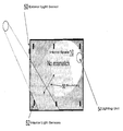
- FIG. 1 shows how exterior light creates different lighting areas in an interior space
- FIG. 2 shows the problem this causes when interior lighting is used in combination with the exterior lighting shown in FIG. 1 ;
- FIG. 3 shows how the color temperature and light intensity vary during the course of a day
- FIG. 4 shows how the variations of FIG. 3 can be mapped to a desired color temperature and intensity profile
- FIG. 5 shows a first example of how a lighting system of the invention can operate
- FIG. 6 shows a second example of how a lighting system of the invention can operate
- FIG. 7 shows a lighting system of the invention
- FIG. 8 is a flow diagram showing the control method of the invention.
- the invention provides a lighting system which uses interior and exterior light sensors for detecting lighting level and color.
- a lighting unit has a controlled color and intensity so that a color match zone can be defined where the interior space lighting has color temperature based on the exterior lighting conditions.
- FIG. 1 shows how exterior light creates different lighting areas in an interior space.
- the interior space (such as a room) is shown as 10 .
- the exterior space 12 (outdoors) provides light to the interior space through a window.
- the light 14 shining in has a color temperature and intensity dependent on the outside conditions.
- the light 14 can be bright sunlight, and reflected and diffused light 16 fills the remainder of the room, but with a lower intensity. There is thus an intensity boundary, but with similar color.
- FIG. 2 shows the problem this causes when interior lighting is used in combination with the exterior lighting shown in FIG. 1 .
- a lighting unit is shown as 20 , and this creates a lighting zone, of decreasing intensity with distance from the lighting unit 20 . Where the lighting zone overlaps with the bright sunlight 14 , there is a mismatch in color temperature, as well as a light intensity boundary.
- FIG. 3 shows how the color temperature and light intensity vary during the course of a day. Near sunrise and sunset, the color temperature is low (such as 3.2K) representing warm colors, whereas in the middle of the day, the color temperature is much higher (such as 6K) representing cool (bluish white) colors. The color temperature is shown in the top plot. The color is generally white, but with a reddish shift at the beginning and end of the day and a bluish shift in the middle of the day.
- the intensity essentially increases to a peak and then decreases as shown in the bottom plot.
- the intensity will vary with faster local fluctuations, representing different cloud cover, and shadowing as a result of the different position of the sun in the sky (by trees, buildings etc), as well as weather conditions (such as snow, clear skies, overcast skies). These fluctuations are shown as the dotted plot.
- FIG. 4 shows how the variations of FIG. 3 can be mapped to a desired default color temperature and intensity profile.
- the top plots are those of FIG. 3 .
- the bottom plots show a standardised color temperature and intensity profile, and these can be used as a default setting.
- FIG. 5 shows a first example of how a lighting system of the invention can operate.
- the lighting system has an exterior light sensor 50 for detecting the exterior lighting color.
- the exterior light intensity can also be measured, although this is not needed for a most basic implementation, since the primary aim is to avoid abrupt color temperature boundaries rather than brightness intensity boundaries.
- the color can be detected using an RGB sensor with a diffuser, or “white card” reflected light measurement can be used. This can be a very simple device.
- a set of similar interior light sensors 52 are positioned around the room, so that a color temperature profile within the interior space can be derived.
- These sensors 52 also measure the light intensity level.
- the lighting unit 54 comprises an LED light fixture with adjustable color and intensity. RGB LED lighting can be used, with accurate wavelength control.
- the lighting unit 54 is controlled using a feedback loop which ensures that there is no mismatch in color temperature at the boundary 56 between light generated principally by the lighting unit and light having a significant content from outside.
- This boundary 56 can be thought of as being located in a color match zone, where the interior space lighting is to be matched in color temperature to the exterior lighting. In the color match zone, shadows are softened.
- the aim of the color matching is primarily to try to match the color temperature but also to adjust the intensity by taking into account the light contribution externally.
- the color temperature of the natural light source is thus copied dynamically.
- the light intensity can also follow the exterior conditions, but using thresholds. For example, when sunlight comes in, the intensity inside is limited so that it will reach a threshold. Similarly, the intensity inside is maintained above a lower threshold. The interior space will thus always be light enough, with the right color temperature inside.
- the bottom graph of FIG. 4 shows one possible intensity profile during the course of the day.
- the profile has lower and upper bounds, but otherwise follows the exterior lighting intensity pattern, so that the user has the feeling of natural light, including the way the intensity of the light evolves during the course of the day.
- the system includes damping/filtering so that the rapid fluctuations shown as the dotted line in the top intensity profile in FIG. 4 are filtered out.
- the light intensity is controlled to provide the desired lighting level, but also to reduce contrast with the exterior light.
- the interior space may be made brighter that would be the case when it is dark outside, to reduce the mismatch at the boundary 56 .
- the interior light intensity can also be a function of the exterior light intensity, as well as always being chosen to provide an adequate level of interior lighting.
- FIG. 6 shows a second example of how a lighting system of the invention can operate.
- the interior space has three zones.
- Zone 60 is a color match zone as previously explained, where there is an interaction between direct (non-reflected) exterior sunlight and the internal lighting.
- Zone 62 is a user defined color zone. This has little light received from the exterior, so that the light color can be controlled, without significant adjustment needed to take account of the external lighting conditions.
- Zone 64 is a color gradient zone between the user defined color zone 62 and the color match zone 60 . This is used to create soft intensity gradients and color gradients between the zones with (zone 60 ) and without (zone 62 ) significant outside light input.
- FIG. 7 shows a lighting system of the invention.
- the outside sensors are shown as OS 1 . . . OS N and the inside sensors are shown as IS 1 . . . IS M .
- the lighting system has lighting units L 1 . . . Lk.
- the sensor signals are all provided to a controller 70 , which generates the control signals for the lighting units.
- the controller 70 also receives user settings which can for example override the feedback system if desired, and for example for defined the user zone 62 .
- the time of day is used as an input by the controller 70 , for example so that the default general intensity and color profiles of FIG. 4 can be followed.
- the geometry input is used to define how the lighting units and sensors are positioned so that suitable control can be implemented.
- the intensity inside follows the outside intensity within boundary limits. These boundary limits are selected so that intensity contrast can still be smoothed inside.
- the color temperature follows the outside color temperature, but again within bounds. This is shown in the color temperature plot at the bottom of FIG. 4 , where a minimum color temperature is provided. Most of the day, the outside color temperature is followed, but not in early morning or late evening, since the lower color outside temperature does not provide good color rendering for eyesight.
- the aims are to provided a good color match between externally lit and internally lit areas and to reduce contrast by adding more light where necessary. This requires monitoring of the external light color, interior illumination level, and optionally external light intensity.
- a specific color temperature inside In a second operating mode, it is desired to have a specific color temperature inside, but outside light has another color temperature.
- the inside light should only add the necessary part of the spectrum (i.e. more red/yellow if the color temperature outside is higher than desired).
- This then defines the user-defined area, and the internal light sensors alone can be used to determine the color that needs to be added.
- the color matching zone then additionally softens the transition to the exterior color temperature when there is a boundary to direct light received from a window, for example. This uses the exterior light sensor.
- FIG. 8 A general, algorithm is shown in FIG. 8 and comprises:
- the desired lighting can be either user-set (static) or depend on the outside condition, and follow the graphs at the bottom of FIG. 4 .
- the control scheme includes a feedback loop which includes monitoring of the internal lighting conditions (step 89 ).
- the color temperature can be calculated for any color, but the invention is particularly concerned with nearly white sources. LEDs enable color control to a resolution that is better than can be detected by a human (for example less than 2.5 nm wavelength shift).
- the shift in color temperature is in practice a red/blue shift.
- the sensors do not need to be at the exact location where color matching is needed. Most surfaces are diffuse reflectors, so incident light is very rapidly spread out over a large area. Interpolation is therefore sufficient to enable control of the system.
- the system of the invention can be used to implement various control strategies. These can include matching the color temperature to the outside light with or without the boundaries explained with reference to FIG. 4 .
- the exterior light sensor can be for color only, or it can be for color and intensity.
- the system can have various settings to override the feedback control method.
- the system can be controlled to follow the default pattern of color temperature and intensity, without using exterior light feedback.
- the system can be controlled to implement a user defined color temperature and intensity inside, and the feedback approach is then used only to soften the boundaries with the light which is coming in from the exterior.
- the control of the lighting to be based on the external light can be confined to a transition zone where there is direct light from outside, or it can be applied to a larger internal area, or can be applied to the full internal area.
Abstract
Description
Claims (20)
Applications Claiming Priority (3)
| Application Number | Priority Date | Filing Date | Title |
|---|---|---|---|
| EP11179808.8 | 2011-09-02 | ||
| EP11179808 | 2011-09-02 | ||
| EP11179808.8A EP2566303B1 (en) | 2011-09-02 | 2011-09-02 | Lighting system |
Publications (2)
| Publication Number | Publication Date |
|---|---|
| US20130057157A1 US20130057157A1 (en) | 2013-03-07 |
| US9210761B2 true US9210761B2 (en) | 2015-12-08 |
Family
ID=44759452
Family Applications (1)
| Application Number | Title | Priority Date | Filing Date |
|---|---|---|---|
| US13/599,118 Active 2033-02-17 US9210761B2 (en) | 2011-09-02 | 2012-08-30 | Lighting system |
Country Status (2)
| Country | Link |
|---|---|
| US (1) | US9210761B2 (en) |
| EP (1) | EP2566303B1 (en) |
Cited By (4)
| Publication number | Priority date | Publication date | Assignee | Title |
|---|---|---|---|---|
| US20170217367A1 (en) * | 2016-02-01 | 2017-08-03 | Magna Electronics Inc. | Vehicle adaptive lighting system |
| US10750597B2 (en) | 2018-05-04 | 2020-08-18 | Crestron Electronics, Inc. | Color temperature sensor |
| US11002605B2 (en) * | 2018-05-04 | 2021-05-11 | Crestron Electronics, Inc. | System and method for calibrating a light color sensor |
| US11060673B2 (en) * | 2016-08-11 | 2021-07-13 | Abl Ip Holding Llc | Luminaires with transition zones for glare control |
Families Citing this family (21)
| Publication number | Priority date | Publication date | Assignee | Title |
|---|---|---|---|---|
| US9645465B2 (en) | 2011-03-16 | 2017-05-09 | View, Inc. | Controlling transitions in optically switchable devices |
| US11635666B2 (en) | 2012-03-13 | 2023-04-25 | View, Inc | Methods of controlling multi-zone tintable windows |
| US11950340B2 (en) | 2012-03-13 | 2024-04-02 | View, Inc. | Adjusting interior lighting based on dynamic glass tinting |
| US11674843B2 (en) | 2015-10-06 | 2023-06-13 | View, Inc. | Infrared cloud detector systems and methods |
| US10048561B2 (en) | 2013-02-21 | 2018-08-14 | View, Inc. | Control method for tintable windows |
| US9638978B2 (en) | 2013-02-21 | 2017-05-02 | View, Inc. | Control method for tintable windows |
| US11719990B2 (en) | 2013-02-21 | 2023-08-08 | View, Inc. | Control method for tintable windows |
| AT14741U1 (en) * | 2014-03-28 | 2016-05-15 | Tridonic Gmbh & Co Kg | Method for controlling a control gear for lamps |
| AT14925U1 (en) * | 2014-03-28 | 2016-08-15 | Tridonic Gmbh & Co Kg | Method for controlling a control gear for lamps |
| AT14740U1 (en) * | 2014-03-28 | 2016-05-15 | Tridonic Gmbh & Co Kg | Lighting system with a control unit |
| TWI823168B (en) | 2015-07-07 | 2023-11-21 | 美商唯景公司 | Viewcontrol methods for tintable windows |
| US11255722B2 (en) | 2015-10-06 | 2022-02-22 | View, Inc. | Infrared cloud detector systems and methods |
| WO2017063888A1 (en) * | 2015-10-13 | 2017-04-20 | Philips Lighting Holding B.V. | Area lighting system and operating method |
| EP3563085B1 (en) * | 2017-01-02 | 2020-08-12 | Signify Holding B.V. | Interior lighting system |
| EP3586570A1 (en) | 2017-02-22 | 2020-01-01 | Signify Holding B.V. | Optimizing multichannel luminaire control using a color coefficient matrix |
| EP3586574A4 (en) * | 2017-02-27 | 2021-01-06 | View, Inc. | Adjusting interior lighting based on dynamic glass tinting |
| CN111096074B (en) | 2017-09-11 | 2023-02-03 | 昕诺飞控股有限公司 | Lighting device |
| CN108770151A (en) * | 2018-06-14 | 2018-11-06 | 苏州数言信息技术有限公司 | Intelligent lighting integrated control system based on scene and method |
| DE102019119986A1 (en) * | 2019-07-24 | 2021-01-28 | Trilux Gmbh & Co. Kg | Luminaire with light color control |
| US11480431B1 (en) * | 2019-08-27 | 2022-10-25 | Alarm.Com Incorporated | Lighting adaptive navigation |
| DE102020121841A1 (en) | 2020-08-20 | 2022-02-24 | Siteco Gmbh | LAMP WITH SENSOR DEVICE FOR MEASUREMENT OF REFLECTED AND AMBIENT LIGHT |
Citations (17)
| Publication number | Priority date | Publication date | Assignee | Title |
|---|---|---|---|---|
| US5721471A (en) * | 1995-03-10 | 1998-02-24 | U.S. Philips Corporation | Lighting system for controlling the color temperature of artificial light under the influence of the daylight level |
| US6052179A (en) * | 1998-04-14 | 2000-04-18 | Physical Optics Corporation | Method and system for determining the wavelength of light transmitted through an optical fiber |
| US20060158881A1 (en) * | 2004-12-20 | 2006-07-20 | Color Kinetics Incorporated | Color management methods and apparatus for lighting devices |
| US20070115658A1 (en) * | 1999-11-18 | 2007-05-24 | Color Kinetics Incorporated | Methods and apparatus for generating and modulating white light illumination conditions |
| US20080302657A1 (en) * | 2007-03-05 | 2008-12-11 | Gentex Corporation | Method and Apparatus for Ion Milling |
| US20080310005A1 (en) * | 2006-12-07 | 2008-12-18 | Tonar William L | Thin-Film Coatings, Electro-Optic Elements and Assemblies Incorporating These Elements |
| US20090118623A1 (en) * | 2005-04-20 | 2009-05-07 | Cvl Cosmetics Sa | Instrument and Method for High-Speed Perfusion Imaging |
| WO2009095853A2 (en) | 2008-01-28 | 2009-08-06 | Nxp B.V. | System and method for estimating the junction temperature of a light emitting diode |
| US20100231131A1 (en) | 2009-03-11 | 2010-09-16 | Anderson Deloren E | Light array maintenance system and method |
| US20110002028A1 (en) * | 2006-03-03 | 2011-01-06 | Gentex Corporation | Thin-Film Coatings, Electro-Optic Elements and Assemblies Incorporating These Elements |
| EP2296436A1 (en) | 2009-09-07 | 2011-03-16 | Nxp B.V. | System and method for output flux measurement of a light emitting diode |
| US20110227487A1 (en) * | 2007-10-09 | 2011-09-22 | Flex Lighting Ii, Llc | Light emitting display with light mixing within a film |
| US8686644B2 (en) * | 2010-03-31 | 2014-04-01 | Ats Automation Tooling Systems Inc. | Light generator systems and methods |
| US8805550B2 (en) * | 2008-04-14 | 2014-08-12 | Digital Lumens Incorporated | Power management unit with power source arbitration |
| US8823277B2 (en) * | 2008-04-14 | 2014-09-02 | Digital Lumens Incorporated | Methods, systems, and apparatus for mapping a network of lighting fixtures with light module identification |
| US8829821B2 (en) * | 2012-12-18 | 2014-09-09 | Cree, Inc. | Auto commissioning lighting fixture |
| US8836243B2 (en) * | 2009-10-08 | 2014-09-16 | Delos Living, Llc | LED lighting system |
-
2011
- 2011-09-02 EP EP11179808.8A patent/EP2566303B1/en active Active
-
2012
- 2012-08-30 US US13/599,118 patent/US9210761B2/en active Active
Patent Citations (18)
| Publication number | Priority date | Publication date | Assignee | Title |
|---|---|---|---|---|
| US5721471A (en) * | 1995-03-10 | 1998-02-24 | U.S. Philips Corporation | Lighting system for controlling the color temperature of artificial light under the influence of the daylight level |
| US6052179A (en) * | 1998-04-14 | 2000-04-18 | Physical Optics Corporation | Method and system for determining the wavelength of light transmitted through an optical fiber |
| US20070115658A1 (en) * | 1999-11-18 | 2007-05-24 | Color Kinetics Incorporated | Methods and apparatus for generating and modulating white light illumination conditions |
| US20060158881A1 (en) * | 2004-12-20 | 2006-07-20 | Color Kinetics Incorporated | Color management methods and apparatus for lighting devices |
| US20090118623A1 (en) * | 2005-04-20 | 2009-05-07 | Cvl Cosmetics Sa | Instrument and Method for High-Speed Perfusion Imaging |
| US20110002028A1 (en) * | 2006-03-03 | 2011-01-06 | Gentex Corporation | Thin-Film Coatings, Electro-Optic Elements and Assemblies Incorporating These Elements |
| US20080310005A1 (en) * | 2006-12-07 | 2008-12-18 | Tonar William L | Thin-Film Coatings, Electro-Optic Elements and Assemblies Incorporating These Elements |
| US20080302657A1 (en) * | 2007-03-05 | 2008-12-11 | Gentex Corporation | Method and Apparatus for Ion Milling |
| US20110227487A1 (en) * | 2007-10-09 | 2011-09-22 | Flex Lighting Ii, Llc | Light emitting display with light mixing within a film |
| US20110031903A1 (en) | 2008-01-28 | 2011-02-10 | Nxp B.V. | System and method for estimating the junction temperature of a light emitting diode |
| WO2009095853A2 (en) | 2008-01-28 | 2009-08-06 | Nxp B.V. | System and method for estimating the junction temperature of a light emitting diode |
| US8805550B2 (en) * | 2008-04-14 | 2014-08-12 | Digital Lumens Incorporated | Power management unit with power source arbitration |
| US8823277B2 (en) * | 2008-04-14 | 2014-09-02 | Digital Lumens Incorporated | Methods, systems, and apparatus for mapping a network of lighting fixtures with light module identification |
| US20100231131A1 (en) | 2009-03-11 | 2010-09-16 | Anderson Deloren E | Light array maintenance system and method |
| EP2296436A1 (en) | 2009-09-07 | 2011-03-16 | Nxp B.V. | System and method for output flux measurement of a light emitting diode |
| US8836243B2 (en) * | 2009-10-08 | 2014-09-16 | Delos Living, Llc | LED lighting system |
| US8686644B2 (en) * | 2010-03-31 | 2014-04-01 | Ats Automation Tooling Systems Inc. | Light generator systems and methods |
| US8829821B2 (en) * | 2012-12-18 | 2014-09-09 | Cree, Inc. | Auto commissioning lighting fixture |
Non-Patent Citations (2)
| Title |
|---|
| Communication pursuant to Article 94(3) EPC for counterpart application EP 11 179 808.8 (Apr. 24, 2015). |
| Extended European Search Report for European Appln. No. 11179808.8 (Nov. 18, 2011). |
Cited By (6)
| Publication number | Priority date | Publication date | Assignee | Title |
|---|---|---|---|---|
| US20170217367A1 (en) * | 2016-02-01 | 2017-08-03 | Magna Electronics Inc. | Vehicle adaptive lighting system |
| US10906463B2 (en) * | 2016-02-01 | 2021-02-02 | Magna Electronics Inc. | Vehicle adaptive lighting system |
| US11305690B2 (en) | 2016-02-01 | 2022-04-19 | Magna Electronics Inc. | Vehicular adaptive lighting control system |
| US11060673B2 (en) * | 2016-08-11 | 2021-07-13 | Abl Ip Holding Llc | Luminaires with transition zones for glare control |
| US10750597B2 (en) | 2018-05-04 | 2020-08-18 | Crestron Electronics, Inc. | Color temperature sensor |
| US11002605B2 (en) * | 2018-05-04 | 2021-05-11 | Crestron Electronics, Inc. | System and method for calibrating a light color sensor |
Also Published As
| Publication number | Publication date |
|---|---|
| EP2566303B1 (en) | 2018-02-28 |
| US20130057157A1 (en) | 2013-03-07 |
| EP2566303A1 (en) | 2013-03-06 |
Similar Documents
| Publication | Publication Date | Title |
|---|---|---|
| US9210761B2 (en) | Lighting system | |
| US7111952B2 (en) | System to control daylight and artificial illumination and sun glare in a space | |
| US9226366B2 (en) | Control system for active window glass managing the colour of the light in a building | |
| US6614013B2 (en) | Illumination management system | |
| EP1606691B1 (en) | System to control daylight and artificial illumination and sun glare in a space | |
| US20050047133A1 (en) | Diode-based light sensors and methods | |
| KR101951391B1 (en) | Discoloration Glass control system and Control method thereof | |
| US10237948B1 (en) | Light controller | |
| US11382192B2 (en) | Preferred lighting spectrum and color shifting circadian lamps | |
| CN103167697A (en) | Color temperature and luminance adaptive lamp | |
| CN104869696A (en) | Intelligent energy-saving household illuminating lamp | |
| JP6388602B2 (en) | Control unit for controlling the color of the window | |
| JPH07235390A (en) | Dimming system in illumination with fluorescent lamp | |
| US20230180369A1 (en) | Immersive outdoor lighting emulation | |
| KR100654373B1 (en) | Method for automatic contrlling luminous intensity by outside-luminosity | |
| EP4147540A1 (en) | Immersive outdoor lighting emulation | |
| JP2004303582A (en) | Lighting control device and luminaire equipped with it | |
| JP2014103081A (en) | Energy-saving controller | |
| KR20130055899A (en) | Led lighting apparatus improved rendering and that method |
Legal Events
| Date | Code | Title | Description |
|---|---|---|---|
| AS | Assignment |
Owner name: NXP B.V., NETHERLANDS Free format text: ASSIGNMENT OF ASSIGNORS INTEREST;ASSIGNORS:NACKAERTS, AXEL;NGUYEN, VIET;SIGNING DATES FROM 20120824 TO 20120829;REEL/FRAME:028875/0511 |
|
| STCF | Information on status: patent grant |
Free format text: PATENTED CASE |
|
| AS | Assignment |
Owner name: MORGAN STANLEY SENIOR FUNDING, INC., MARYLAND Free format text: SECURITY AGREEMENT SUPPLEMENT;ASSIGNOR:NXP B.V.;REEL/FRAME:038017/0058 Effective date: 20160218 |
|
| AS | Assignment |
Owner name: MORGAN STANLEY SENIOR FUNDING, INC., MARYLAND Free format text: CORRECTIVE ASSIGNMENT TO CORRECT THE REMOVE APPLICATION 12092129 PREVIOUSLY RECORDED ON REEL 038017 FRAME 0058. ASSIGNOR(S) HEREBY CONFIRMS THE SECURITY AGREEMENT SUPPLEMENT;ASSIGNOR:NXP B.V.;REEL/FRAME:039361/0212 Effective date: 20160218 |
|
| AS | Assignment |
Owner name: MORGAN STANLEY SENIOR FUNDING, INC., MARYLAND Free format text: CORRECTIVE ASSIGNMENT TO CORRECT THE REMOVE APPLICATION 12681366 PREVIOUSLY RECORDED ON REEL 039361 FRAME 0212. ASSIGNOR(S) HEREBY CONFIRMS THE SECURITY AGREEMENT SUPPLEMENT;ASSIGNOR:NXP B.V.;REEL/FRAME:042762/0145 Effective date: 20160218 Owner name: MORGAN STANLEY SENIOR FUNDING, INC., MARYLAND Free format text: CORRECTIVE ASSIGNMENT TO CORRECT THE REMOVE APPLICATION 12681366 PREVIOUSLY RECORDED ON REEL 038017 FRAME 0058. ASSIGNOR(S) HEREBY CONFIRMS THE SECURITY AGREEMENT SUPPLEMENT;ASSIGNOR:NXP B.V.;REEL/FRAME:042985/0001 Effective date: 20160218 |
|
| MAFP | Maintenance fee payment |
Free format text: PAYMENT OF MAINTENANCE FEE, 4TH YEAR, LARGE ENTITY (ORIGINAL EVENT CODE: M1551); ENTITY STATUS OF PATENT OWNER: LARGE ENTITY Year of fee payment: 4 |
|
| AS | Assignment |
Owner name: NXP B.V., NETHERLANDS Free format text: RELEASE BY SECURED PARTY;ASSIGNOR:MORGAN STANLEY SENIOR FUNDING, INC.;REEL/FRAME:050745/0001 Effective date: 20190903 |
|
| AS | Assignment |
Owner name: MORGAN STANLEY SENIOR FUNDING, INC., MARYLAND Free format text: CORRECTIVE ASSIGNMENT TO CORRECT THE REMOVE APPLICATION 12298143 PREVIOUSLY RECORDED ON REEL 042762 FRAME 0145. ASSIGNOR(S) HEREBY CONFIRMS THE SECURITY AGREEMENT SUPPLEMENT;ASSIGNOR:NXP B.V.;REEL/FRAME:051145/0184 Effective date: 20160218 Owner name: MORGAN STANLEY SENIOR FUNDING, INC., MARYLAND Free format text: CORRECTIVE ASSIGNMENT TO CORRECT THE REMOVE APPLICATION 12298143 PREVIOUSLY RECORDED ON REEL 039361 FRAME 0212. ASSIGNOR(S) HEREBY CONFIRMS THE SECURITY AGREEMENT SUPPLEMENT;ASSIGNOR:NXP B.V.;REEL/FRAME:051029/0387 Effective date: 20160218 Owner name: MORGAN STANLEY SENIOR FUNDING, INC., MARYLAND Free format text: CORRECTIVE ASSIGNMENT TO CORRECT THE REMOVE APPLICATION 12298143 PREVIOUSLY RECORDED ON REEL 042985 FRAME 0001. ASSIGNOR(S) HEREBY CONFIRMS THE SECURITY AGREEMENT SUPPLEMENT;ASSIGNOR:NXP B.V.;REEL/FRAME:051029/0001 Effective date: 20160218 Owner name: MORGAN STANLEY SENIOR FUNDING, INC., MARYLAND Free format text: CORRECTIVE ASSIGNMENT TO CORRECT THE REMOVE APPLICATION12298143 PREVIOUSLY RECORDED ON REEL 042985 FRAME 0001. ASSIGNOR(S) HEREBY CONFIRMS THE SECURITY AGREEMENT SUPPLEMENT;ASSIGNOR:NXP B.V.;REEL/FRAME:051029/0001 Effective date: 20160218 Owner name: MORGAN STANLEY SENIOR FUNDING, INC., MARYLAND Free format text: CORRECTIVE ASSIGNMENT TO CORRECT THE REMOVE APPLICATION12298143 PREVIOUSLY RECORDED ON REEL 039361 FRAME 0212. ASSIGNOR(S) HEREBY CONFIRMS THE SECURITY AGREEMENT SUPPLEMENT;ASSIGNOR:NXP B.V.;REEL/FRAME:051029/0387 Effective date: 20160218 Owner name: MORGAN STANLEY SENIOR FUNDING, INC., MARYLAND Free format text: CORRECTIVE ASSIGNMENT TO CORRECT THE REMOVE APPLICATION 12298143 PREVIOUSLY RECORDED ON REEL 038017 FRAME 0058. ASSIGNOR(S) HEREBY CONFIRMS THE SECURITY AGREEMENT SUPPLEMENT;ASSIGNOR:NXP B.V.;REEL/FRAME:051030/0001 Effective date: 20160218 Owner name: MORGAN STANLEY SENIOR FUNDING, INC., MARYLAND Free format text: CORRECTIVE ASSIGNMENT TO CORRECT THE REMOVE APPLICATION12298143 PREVIOUSLY RECORDED ON REEL 042762 FRAME 0145. ASSIGNOR(S) HEREBY CONFIRMS THE SECURITY AGREEMENT SUPPLEMENT;ASSIGNOR:NXP B.V.;REEL/FRAME:051145/0184 Effective date: 20160218 |
|
| MAFP | Maintenance fee payment |
Free format text: PAYMENT OF MAINTENANCE FEE, 8TH YEAR, LARGE ENTITY (ORIGINAL EVENT CODE: M1552); ENTITY STATUS OF PATENT OWNER: LARGE ENTITY Year of fee payment: 8 |