US9217697B2 - Apparatus, system, and method for collecting a target material - Google Patents

Apparatus, system, and method for collecting a target material Download PDF

Info

Publication number
US9217697B2
US9217697B2 US14/665,368 US201514665368A US9217697B2 US 9217697 B2 US9217697 B2 US 9217697B2 US 201514665368 A US201514665368 A US 201514665368A US 9217697 B2 US9217697 B2 US 9217697B2
Authority
US
United States
Prior art keywords
target material
collector
sub
fraction
vessel
Prior art date
Legal status (The legal status is an assumption and is not a legal conclusion. Google has not performed a legal analysis and makes no representation as to the accuracy of the status listed.)
Active
Application number
US14/665,368
Other versions
US20150192506A1 (en
Inventor
Lance U'ren
Jennifer Chow
Current Assignee (The listed assignees may be inaccurate. Google has not performed a legal analysis and makes no representation or warranty as to the accuracy of the list.)
Rarecyte Inc
Original Assignee
Rarecyte Inc
Priority date (The priority date is an assumption and is not a legal conclusion. Google has not performed a legal analysis and makes no representation as to the accuracy of the date listed.)
Filing date
Publication date
Priority claimed from US14/090,337 external-priority patent/US20140161688A1/en
Priority claimed from US14/266,939 external-priority patent/US20140349828A1/en
Priority claimed from US14/495,449 external-priority patent/US9039999B2/en
Priority claimed from US14/610,522 external-priority patent/US9539570B2/en
Assigned to RARECYTE, INC. reassignment RARECYTE, INC. ASSIGNMENT OF ASSIGNORS INTEREST (SEE DOCUMENT FOR DETAILS). Assignors: CHOW, Jennifer, U'REN, Lance
Priority to US14/665,368 priority Critical patent/US9217697B2/en
Application filed by Rarecyte Inc filed Critical Rarecyte Inc
Publication of US20150192506A1 publication Critical patent/US20150192506A1/en
Priority to US14/883,071 priority patent/US9625360B2/en
Publication of US9217697B2 publication Critical patent/US9217697B2/en
Application granted granted Critical
Priority to US15/019,697 priority patent/US9513291B2/en
Priority to US15/173,692 priority patent/US9541481B2/en
Priority to US15/341,131 priority patent/US10054524B2/en
Assigned to WESTERN ALLIANCE BANK, AN ARIZONA CORPORATION reassignment WESTERN ALLIANCE BANK, AN ARIZONA CORPORATION SECURITY INTEREST (SEE DOCUMENT FOR DETAILS). Assignors: RARECYTE, INC.
Assigned to RARECYTE, INC. reassignment RARECYTE, INC. RELEASE BY SECURED PARTY (SEE DOCUMENT FOR DETAILS). Assignors: WESTERN ALLIANCE BANK, AN ARIZONA CORPORATION
Active legal-status Critical Current
Anticipated expiration legal-status Critical

Links

Images

Classifications

    • GPHYSICS
    • G01MEASURING; TESTING
    • G01NINVESTIGATING OR ANALYSING MATERIALS BY DETERMINING THEIR CHEMICAL OR PHYSICAL PROPERTIES
    • G01N1/00Sampling; Preparing specimens for investigation
    • G01N1/28Preparing specimens for investigation including physical details of (bio-)chemical methods covered elsewhere, e.g. G01N33/50, C12Q
    • G01N1/40Concentrating samples
    • G01N1/4077Concentrating samples by other techniques involving separation of suspended solids
    • GPHYSICS
    • G01MEASURING; TESTING
    • G01NINVESTIGATING OR ANALYSING MATERIALS BY DETERMINING THEIR CHEMICAL OR PHYSICAL PROPERTIES
    • G01N33/00Investigating or analysing materials by specific methods not covered by groups G01N1/00 - G01N31/00
    • G01N33/48Biological material, e.g. blood, urine; Haemocytometers
    • G01N33/483Physical analysis of biological material
    • G01N33/487Physical analysis of biological material of liquid biological material
    • G01N33/49Blood
    • G01N33/491Blood by separating the blood components
    • BPERFORMING OPERATIONS; TRANSPORTING
    • B01PHYSICAL OR CHEMICAL PROCESSES OR APPARATUS IN GENERAL
    • B01LCHEMICAL OR PHYSICAL LABORATORY APPARATUS FOR GENERAL USE
    • B01L3/00Containers or dishes for laboratory use, e.g. laboratory glassware; Droppers
    • B01L3/50Containers for the purpose of retaining a material to be analysed, e.g. test tubes
    • B01L3/502Containers for the purpose of retaining a material to be analysed, e.g. test tubes with fluid transport, e.g. in multi-compartment structures
    • B01L3/5021Test tubes specially adapted for centrifugation purposes
    • B01L3/50215Test tubes specially adapted for centrifugation purposes using a float to separate phases
    • BPERFORMING OPERATIONS; TRANSPORTING
    • B01PHYSICAL OR CHEMICAL PROCESSES OR APPARATUS IN GENERAL
    • B01LCHEMICAL OR PHYSICAL LABORATORY APPARATUS FOR GENERAL USE
    • B01L3/00Containers or dishes for laboratory use, e.g. laboratory glassware; Droppers
    • B01L3/56Labware specially adapted for transferring fluids
    • B01L3/563Joints or fittings ; Separable fluid transfer means to transfer fluids between at least two containers, e.g. connectors
    • B01L3/5635Joints or fittings ; Separable fluid transfer means to transfer fluids between at least two containers, e.g. connectors connecting two containers face to face, e.g. comprising a filter
    • BPERFORMING OPERATIONS; TRANSPORTING
    • B03SEPARATION OF SOLID MATERIALS USING LIQUIDS OR USING PNEUMATIC TABLES OR JIGS; MAGNETIC OR ELECTROSTATIC SEPARATION OF SOLID MATERIALS FROM SOLID MATERIALS OR FLUIDS; SEPARATION BY HIGH-VOLTAGE ELECTRIC FIELDS
    • B03DFLOTATION; DIFFERENTIAL SEDIMENTATION
    • B03D3/00Differential sedimentation
    • CCHEMISTRY; METALLURGY
    • C12BIOCHEMISTRY; BEER; SPIRITS; WINE; VINEGAR; MICROBIOLOGY; ENZYMOLOGY; MUTATION OR GENETIC ENGINEERING
    • C12QMEASURING OR TESTING PROCESSES INVOLVING ENZYMES, NUCLEIC ACIDS OR MICROORGANISMS; COMPOSITIONS OR TEST PAPERS THEREFOR; PROCESSES OF PREPARING SUCH COMPOSITIONS; CONDITION-RESPONSIVE CONTROL IN MICROBIOLOGICAL OR ENZYMOLOGICAL PROCESSES
    • C12Q1/00Measuring or testing processes involving enzymes, nucleic acids or microorganisms; Compositions therefor; Processes of preparing such compositions
    • C12Q1/68Measuring or testing processes involving enzymes, nucleic acids or microorganisms; Compositions therefor; Processes of preparing such compositions involving nucleic acids
    • C12Q1/6806Preparing nucleic acids for analysis, e.g. for polymerase chain reaction [PCR] assay
    • BPERFORMING OPERATIONS; TRANSPORTING
    • B01PHYSICAL OR CHEMICAL PROCESSES OR APPARATUS IN GENERAL
    • B01DSEPARATION
    • B01D21/00Separation of suspended solid particles from liquids by sedimentation
    • B01D21/26Separation of sediment aided by centrifugal force or centripetal force
    • B01D21/262Separation of sediment aided by centrifugal force or centripetal force by using a centrifuge
    • BPERFORMING OPERATIONS; TRANSPORTING
    • B01PHYSICAL OR CHEMICAL PROCESSES OR APPARATUS IN GENERAL
    • B01LCHEMICAL OR PHYSICAL LABORATORY APPARATUS FOR GENERAL USE
    • B01L2200/00Solutions for specific problems relating to chemical or physical laboratory apparatus
    • B01L2200/02Adapting objects or devices to another
    • B01L2200/026Fluid interfacing between devices or objects, e.g. connectors, inlet details
    • BPERFORMING OPERATIONS; TRANSPORTING
    • B01PHYSICAL OR CHEMICAL PROCESSES OR APPARATUS IN GENERAL
    • B01LCHEMICAL OR PHYSICAL LABORATORY APPARATUS FOR GENERAL USE
    • B01L2300/00Additional constructional details
    • B01L2300/06Auxiliary integrated devices, integrated components
    • B01L2300/0672Integrated piercing tool
    • BPERFORMING OPERATIONS; TRANSPORTING
    • B01PHYSICAL OR CHEMICAL PROCESSES OR APPARATUS IN GENERAL
    • B01LCHEMICAL OR PHYSICAL LABORATORY APPARATUS FOR GENERAL USE
    • B01L2300/00Additional constructional details
    • B01L2300/08Geometry, shape and general structure
    • B01L2300/0848Specific forms of parts of containers
    • B01L2300/0851Bottom walls
    • BPERFORMING OPERATIONS; TRANSPORTING
    • B01PHYSICAL OR CHEMICAL PROCESSES OR APPARATUS IN GENERAL
    • B01LCHEMICAL OR PHYSICAL LABORATORY APPARATUS FOR GENERAL USE
    • B01L2400/00Moving or stopping fluids
    • B01L2400/06Valves, specific forms thereof
    • B01L2400/0677Valves, specific forms thereof phase change valves; Meltable, freezing, dissolvable plugs; Destructible barriers
    • B01L2400/0683Valves, specific forms thereof phase change valves; Meltable, freezing, dissolvable plugs; Destructible barriers mechanically breaking a wall or membrane within a channel or chamber
    • BPERFORMING OPERATIONS; TRANSPORTING
    • B01PHYSICAL OR CHEMICAL PROCESSES OR APPARATUS IN GENERAL
    • B01LCHEMICAL OR PHYSICAL LABORATORY APPARATUS FOR GENERAL USE
    • B01L9/00Supporting devices; Holding devices
    • B01L9/50Clamping means, tongs
    • YGENERAL TAGGING OF NEW TECHNOLOGICAL DEVELOPMENTS; GENERAL TAGGING OF CROSS-SECTIONAL TECHNOLOGIES SPANNING OVER SEVERAL SECTIONS OF THE IPC; TECHNICAL SUBJECTS COVERED BY FORMER USPC CROSS-REFERENCE ART COLLECTIONS [XRACs] AND DIGESTS
    • Y10TECHNICAL SUBJECTS COVERED BY FORMER USPC
    • Y10TTECHNICAL SUBJECTS COVERED BY FORMER US CLASSIFICATION
    • Y10T436/00Chemistry: analytical and immunological testing
    • Y10T436/25Chemistry: analytical and immunological testing including sample preparation
    • Y10T436/25375Liberation or purification of sample or separation of material from a sample [e.g., filtering, centrifuging, etc.]

Definitions

  • This disclosure relates generally to density-based fluid separation and, in particular, to retrieving fetal material from a suspension.
  • Suspensions often include materials of interests that are difficult to detect, extract and isolate for analysis.
  • whole blood is a suspension of materials in a fluid.
  • the materials include billions of red and white blood cells and platelets in a proteinaceous fluid called plasma.
  • Whole blood is routinely examined for the presence of abnormal organisms or cells, such as ova, fetal cells, endothelial cells, parasites, bacteria, and inflammatory cells, and viruses, including HIV, cytomegalovirus, hepatitis C virus, and Epstein-Barr virus.
  • Typical techniques used to analyze a blood sample include the steps of smearing a film of blood on a slide and staining the film in a way that enables certain components to be examined by bright field or fluorescence microscopy.
  • FIGS. 1A-1B show an example collector.
  • FIGS. 2A-2B show an example collector.
  • FIGS. 2C-2D show an example collector.
  • FIGS. 3A-3B show an example collector-processing vessel system.
  • FIGS. 4A-4B show an example collector-canopy system.
  • FIGS. 5A-5B show an example sealing ring.
  • FIGS. 5C-5D show an example sealing ring.
  • FIGS. 5E-5F show an example sealing ring.
  • FIG. 5G shows an example sealing ring.
  • FIG. 6 shows a flow diagram of an example method for retrieving a target material.
  • FIGS. 7A-7B show example float and primary vessel systems.
  • FIG. 8 shows an example float and primary vessel system having undergone density-based separation.
  • FIG. 9 shows an example sealing ring and the example float and primary vessel system forming a seal.
  • FIGS. 10A-10G show an example system retrieving a target material.
  • a system includes a processing vessel, such as an Eppendorf tube, a syringe or a test tube, and a collector.
  • the collector is sized and shaped to fit into a primary vessel, such as a test tube.
  • the collector funnels the target material from the suspension through a cannula and into the processing vessel.
  • the cannula extends into a cavity at a first end of the collector that holds the processing vessel.
  • the collector includes a concave opening at a second end in fluid communication with the cannula.
  • the processing vessel includes at least one displacement fluid to be expelled, such that the at least one displacement fluid pushes the target material into the collector.
  • FIG. 1A shows an isometric view of a collector 100 .
  • FIG. 1B shows a cross-sectional view of the collector 100 taken along the line I-I shown in FIG. 1A .
  • Dot-dashed line 102 represents the central or highest-symmetry axis of the collector 100 .
  • the collector 100 may be sized and shaped to fit within a primary vessel containing or capable of holding a suspension, the suspension suspected of including target material.
  • the collector 100 funnels the target material from the suspension through a cannula 106 and into a processing vessel (not shown) to be located within a cavity 108 .
  • the collector 100 includes the main body 104 which includes a first end 110 and a second end 112 .
  • a seal may be formed between the second end 112 and an inner wall of the primary vessel to maintain a fluid-tight sealing engagement before, during, and after centrifugation and to inhibit any portion of the suspension from being located or flowing between an inner wall of the primary vessel and a main body 104 of the collector 100 .
  • the seal may be formed by an interference fit, a grease (such as vacuum grease), an adhesive, an epoxy, by bonding (such as by thermal bonding), by welding (such as by ultrasonic welding), by clamping (such as with a ring or clamp), an insert (such as an O-ring or a collar) that fits between the second end 112 and the inner wall of the primary vessel, or the like.
  • the main body 104 may be any appropriate shape, including, but not limited to, cylindrical, triangular, square, rectangular, or the like.
  • the collector 100 also includes an internal concave opening 114 which tapers toward the cannula 106 from the second end 112 .
  • the concave opening 114 channels target material from below the second end 112 into the cannula 106 which is connected to, and in fluid communication with, an apex of the concave opening 114 .
  • the apex of the concave opening 114 has a smaller diameter than the mouth of the concave opening 114 .
  • the concave opening 114 is formed by a tapered wall that may be straight, curvilinear, arcuate, or the like.
  • the concave opening 114 may be any appropriate shape, including, but not limited to, tubular, spherical, domed, conical, rectangular, pyramidal, or the like. Furthermore, the outermost diameter or edge of the concave opening 114 may be in continuous communication or constant contact (i.e. sit flush) with the inner wall of the primary vessel such that no dead space is present between the second end 112 of the collector 100 and the inner wall of the primary vessel.
  • the cannula 106 such as a tube or a needle, including, but not limited to a non-coring needle, extends from the apex of the concave opening 114 and into the cavity 108 .
  • the cavity 108 is a concave opening extending from the first end 110 into the main body 104 and may accept and support the processing vessel (not shown).
  • the cavity 108 may be any appropriate depth to accept and support the processing vessel (not shown).
  • the cannula 106 may extend any appropriate distance into the cavity 108 in order to puncture the base of, or be inserted into, the processing vessel (not shown).
  • the cannula 106 may include a flat tip, a beveled tip, a sharpened tip, or a tapered tip.
  • the cavity 108 may be any appropriate shape, including, but not limited to, tubular, spherical, domed, conical, rectangular, pyramidal, or the like.
  • the cavity 108 may be threaded to engage a threaded portion of the processing vessel (not shown).
  • the collector 100 may also include a retainer (not shown) to prevent the collector 100 from sliding relative to the primary vessel, thereby keeping the collector 100 at a pre-determined height within the primary vessel.
  • the retainer (not shown) may be a shoulder extending radially from the first end 110 , a clip, a circular protrusion that extends beyond the circumference of the cylindrical main body 104 , a detent, or the like.
  • FIG. 2A shows an isometric view of a collector 200 .
  • FIG. 2B shows a cross-section view of the collector 200 taken along the line II-II shown in FIG. 2A .
  • Dot-dashed line 202 represents the central or highest-symmetry axis of the collector 200 .
  • the collector 200 is similar to the collector 100 , except that the collector 200 includes a main body 204 that is more elongated than the main body of the collector 100 in order to accommodate a greater portion of the processing vessel (not shown).
  • the main body 204 includes a first end 206 and a second end 208 .
  • a seal may be formed between the second end 208 and an inner wall of the primary vessel to maintain a fluid-tight sealing engagement before, during, and after centrifugation and to inhibit any portion of the suspension flowing between an inner wall of the primary vessel and the main body 204 of the collector 200 .
  • the seal may be formed by an interference fit, a grease (such as vacuum grease), an adhesive, an epoxy, by bonding (such as thermal bonding), by welding (such as ultrasonic welding), clamping (such as with a ring or clamp), an insert (such as an O-ring or a collar) that fits between the second end 208 and the inner wall of the primary vessel, or the like.
  • the first end 206 includes a cavity 212 dimensioned to accept and hold at least a portion of the processing vessel (not shown).
  • the cavity 212 may have a tapered or stepped bottom end 220 on which the processing vessel (not shown) may rest.
  • the first end 206 may also include at least one cut-out 210 to permit proper grip of the processing vessel (not shown) for insertion and removal.
  • the collector 200 funnels the target material from the suspension into an internal concave opening 222 at the second end 208 , through a cannula 214 , and into a processing vessel (not shown) located within the cavity 212 .
  • the cannula 214 may rest on a shelf 224 so that an inner bore of the cannula 214 sits flush with an inner wall of the concave opening 222 , as shown in FIG. 2B .
  • the collector 200 may include a shoulder 216 , which extends circumferentially around the main body 204 .
  • the shoulder 216 may be larger than the inner diameter of the primary vessel so as to rest on the open end of the primary vessel and, upon applying a lock ring (not shown) to the outside of the primary vessel and the shoulder 216 , to inhibit movement of the collector 200 relative to the primary vessel.
  • the lock ring (not shown) applies pressure to the primary vessel along the shoulder 216 .
  • the lock ring may be a two-piece ring, a one piece ring wrapping around the full circumference of the primary vessel, or a one piece ring wrapping around less than the full circumference of the primary vessel, such as one-half (1 ⁇ 2), five-eighths (5 ⁇ 8), two-thirds (2 ⁇ 3), three-quarters (3 ⁇ 4), seven-eighths (7 ⁇ 8), or the like.
  • the shoulder 216 may fit within the primary vessel.
  • the shoulder 216 may be a clip, such that the shoulder 216 may include a catch into which the primary vessel may be inserted to inhibit movement of the collector 200 relative to the primary vessel.
  • the shoulder 216 may form an interference fit with the inner wall of the primary vessel around which a seal ring may be placed.
  • the collector 200 may include at least one window 218 to access the cavity 212 through an inner wall of the main body 204 .
  • the at least one window 218 permits an operator to confirm proper placement of the processing vessel (not shown) within the cavity 212 .
  • the at least one window 218 also allows fluid discharged from the cannula 214 to flow out of the collector 200 and into a space formed between the collector 200 and the primary vessel (not shown) and above the seal between the second end 208 and the inner wall of the primary vessel.
  • FIG. 2C shows an isometric view of a collector 230 .
  • FIG. 2D shows a cross-section view of the collector 230 taken along the line III-III shown in FIG. 2C .
  • the collector 230 is similar to the collector 200 , except that the collector 230 includes a main body 238 including an extension 234 extending away from a first end 232 and a lid 236 to at least temporarily seal an opening 240 within the extension 234 .
  • the opening 240 may be in fluid communication with the cavity 212 at the first end 232 .
  • the lid 236 may removable, puncturable and resealable (e.g. a flap lid), or puncturable and non-resealable (e.g. a foil lid).
  • the extension 234 may be sized to accept the lid 236 when punctured such that a portion of the lid 236 does not extend into the cavity 212 at the first end 232 .
  • the collector 230 does not include the at least one cut-out 210 .
  • the main body can be composed of a variety of different materials including, but not limited to, a ceramic; metals; organic or inorganic materials; and plastic materials, such as polyoxymethylene (“Delrin®”), polystyrene, acrylonitrile butadiene styrene (“ABS”) copolymers, aromatic polycarbonates, aromatic polyesters, carboxymethylcellulose, ethyl cellulose, ethylene vinyl acetate copolymers, nylon, polyacetals, polyacetates, polyacrylonitrile and other nitrile resins, polyacrylonitrile-vinyl chloride copolymer, polyamides, aromatic polyamides (“aramids”), polyamide-imide, polyarylates, polyarylene oxides, polyarylene sulfides, polyarylsulfones, polybenzimidazole, polybutylene terephthalate, polycarbonates, polyester, polyester imides, polyether sulfones, polyetherimides, polyetherketones,
  • the cannula can be composed of a variety of different materials including, but not limited to, a ceramic; metals; organic or inorganic materials; and plastic materials, such as a polypropylene, acrylic, polycarbonate, or the like; and combinations thereof.
  • the cannula may have a tip along a longitudinal axis of the cannula.
  • FIG. 3A shows an exploded view of the example collector 200 and processing vessel 302 .
  • FIG. 3B shows a cross-sectional view of the processing vessel 302 inserted into the cavity 212 at the first end 206 of the collector 200 taken along the line IV-IV shown in FIG. 3A .
  • the collector 200 and processing vessel 302 form a collector-processing vessel system 300 .
  • the processing vessel 302 may be an Eppendorf tube, a syringe, or a test tube and has a closed end 304 and an open end 306 .
  • the open end 306 is sized to receive a cap 308 .
  • the cap 308 may be composed of re-sealable rubber or other suitable re-sealable material that can be repeatedly punctured with a needle or other sharp implement to access the contents stored in the processing vessel 302 interior and re-seals when the needle or implement is removed.
  • the processing vessel 302 may also have two open ends that are sized to receive caps.
  • the processing vessel 302 may have a tapered geometry that widens or narrows toward the open end 306 ; the processing vessel 302 may have a generally cylindrical geometry; or, the processing vessel 302 may have a generally cylindrical geometry in a first segment and a cone-shaped geometry in a second segment, where the first and second segments are connected and continuous with each other.
  • the processing vessel 302 can be composed of a transparent, semitransparent, opaque, or translucent material, such as plastic or another suitable material.
  • the processing vessel includes a central axis 314 , which when inserted into the cavity 212 is coaxial with the central axis 202 of the collector 200 .
  • the processing vessel 302 may also include a plug 310 at the closed end 304 to permit the introduction of the target material or to exchange the target material with a displacement fluid 312 .
  • the closed end 304 may be threaded to provide for a threaded connection with a threaded cavity 212 of the collector 200 .
  • the processing vessel 302 may be composed of glass, plastic, or other suitable material.
  • the plug 310 may be composed of re-sealable rubber or other suitable re-sealable material that can be repeatedly punctured with a needle or other sharp implement to access the contents of the processing vessel 302 interior or permit introduction of contents into the processing vessel 302 and re-seals when the needle or implement is removed.
  • the plug 310 may be inserted into the processing vessel 302 such that a seal is maintained between the plug 310 and the processing vessel 302 , such as by an interference fit.
  • the plug 310 can be formed in the closed end 304 of the processing vessel 302 using heated liquid rubber that can be shaped while warm or hot and hardens as the rubber cools.
  • An adhesive may be used to attach a plug 310 to the inner wall of the processing vessel can be a polymer-based adhesive, an epoxy, a contact adhesive or any other suitable material for bonding or creating a thermal bond.
  • the plug 310 may be injected into the processing vessel 302 .
  • the plug 310 may be thermally bonded to the processing vessel 302 .
  • the cannula 214 has a tapered tip that punctures the plug 310 and extends into an inner cavity of the processing vessel 302 with the shaft of the cannula 214 not extending into the inner cavity of the processing vessel 302 .
  • the inner cavity of the processing vessel 302 holds the target material.
  • the cannula 214 may be covered by a resealable sleeve (not shown) to prevent the target material from flowing out unless the processing vessel 302 is in the cavity 212 to a depth that allows the cannula 214 to just penetrate the processing vessel 302 .
  • the resealable sleeve (not shown) covers the cannula 214 , is spring-resilient, can be penetrated by the cannula 214 , and is made of an elastomeric material capable of withstanding repeated punctures while still maintaining a seal.
  • the processing vessel 302 may be loaded with a displacement fluid 312 prior to insertion into the collector 200 .
  • the displacement fluid 312 displaces the target material, such that when the collector 200 and processing vessel 302 are inserted into the primary vessel (not shown) including the target material, and the collector, processing vessel, and primary vessel undergo centrifugation, the displacement fluid 312 flows out of the processing vessel 302 and into the primary vessel, and, through displacement, such as through buoyant displacement (i.e. lifting a material upwards), pushes the target material through the cannula 214 and into the processing vessel 302 .
  • buoyant displacement i.e. lifting a material upwards
  • the displacement fluid 312 has a greater density than the density of the desired target material of the suspension (the density may be greater than the density of a subset of suspension fractions or all of the suspension fractions) and is inert with respect to the suspension materials.
  • the displacement fluid may have a density that is approximately 0.0001 to approximately 0.1 g/cm 3 greater than the density of the desired target material.
  • the displacement fluid 312 may be miscible or immiscible in the suspension fluid.
  • suitable displacement fluids include, but are not limited to, solution of colloidal silica particles coated with polyvinylpyrrolidone (e.g. Percoll), polysaccharide solution (e.g. Ficoll), iodixanol (e.g.
  • an organic solvent such as 1,4-Dioxane, acetonitrile, ethyl acetate, tert-butanol, cyclohexanone, methylene chloride, tert-Amyl alcohol, Cert-Butyl methyl ether, butyl acetate, hexanol, nitrobenzene, toluene, octanol, octane, propylene carbonate, tetramethylene sulfones, and ionic liquids; polymer-based solutions; surfactants; perfluoroketones, such as perfluor
  • the processing vessel 302 may also include a processing solution (not shown) to effect a transformation on the target material when the target material enters the processing vessel 302 .
  • the processing solution (not shown) may be a preservative, a cell adhesion solution, a dye, or the like. Unlike the displacement fluid 312 , most, if not all, of the processing solution (not shown) remains within the processing vessel 302 upon centrifugation, thereby effecting the transformation on the target material in one manner or another (i.e. preserving, increasing adhesion properties, or the like).
  • the processing solution (not shown) may be introduced as a liquid or as a liquid contained in a casing.
  • the casing may be dissolvable in an aqueous solution but not in the displacement fluid 312 (such as gel cap); or, the casing may be breakable, such that the casing breaks when the processing vessel 302 is shaken in a vortex mixer. Additionally, more than one processing solution may be used.
  • the processing vessel 302 may include a flexible cap that can be pushed to dispense a pre-determined volume therefrom and onto a substrate, such as a slide or a well plate.
  • the cap 308 may be flexible or the cap 308 may be removed and the flexible cap inserted into the open end 306 .
  • the processing vessel 302 may be attached to (i.e. after accumulating the target material) or may include a dispenser, which is capable of dispensing a pre-determined volume of target material from the processing vessel 302 onto another substrate, such as a microscope slide.
  • the dispenser may repeatedly puncture the re-sealable cap 308 or compress the material within the processing vessel 302 to withdraw and dispense the pre-determined volume of target material onto the substrate.
  • the cap 308 may be removed and the dispenser (not shown) may be inserted directly into the processing vessel 302 to dispense the buffy coat-processing solution mixture.
  • FIG. 4A shows an exploded view of the example collector 200 and a canopy 402 .
  • FIG. 4B shows a cross-sectional view of the canopy 402 inserted into the cavity 212 of the collector 200 taken along the line V-V shown in FIG. 4A .
  • the collector 200 and canopy 402 form a collector-canopy system 400 .
  • the canopy 402 is similar to the processing vessel 302 , except that the canopy has a second open end 404 .
  • some fluid within the primary vessel such as a portion of the suspension, a portion of a suspension fraction, a portion of a clearing fluid, or the like, may be discharged through the cannula 214 .
  • the canopy 402 inhibits a portion of the fluid in the primary vessel that may be discharged through the cannula 214 from escaping from the opening of the first end 206 of the collector 200 .
  • the discharged fluid having been blocked by the canopy 402 , flows out of the second open end 404 , and out of the window 218 .
  • Dashed lines 406 show fluid flow as the fluid is discharged through the cannula 214 and retained by the canopy 402 .
  • the lid 236 of the collector 230 inhibits a portion of the fluid in the primary vessel that may be discharged through the cannula 214 from escaping from the opening of the first end 206 of the collector 200 in a manner similar to that of the canopy 402 .
  • FIG. 5A shows an isometric view of a sealing ring 500 .
  • FIG. 5B shows a top down view of the sealing ring 500 .
  • Dot-dashed line 502 represents the central or highest-symmetry axis of the sealing ring 500 .
  • the sealing ring 500 includes an inner wall 504 , an outer wall 506 , and a cavity 508 .
  • R IW represents the radial distance from the center of the sealing ring 500 to the inner wall 504
  • R OW represents the radial distance from the center of the sealing ring 500 to the outer wall 506 .
  • the sealing ring 500 is configured to fit around a primary vessel, such as a tube.
  • the cavity 508 is sized and shaped to receive the primary vessel.
  • the sealing ring 500 may be tightened, such that the size of the cavity 508 and the radii of the inner and outer walls 504 and 506 are reduced by circumferentially applying an approximately uniform, radial force, such as the radial force created by a clamp, around the outer wall 506 directed to the central axis 502 of the sealing ring 500 .
  • an approximately uniform, radial force such as the radial force created by a clamp
  • the sealing ring 500 is tightened around the primary vessel, the uniform force applied to the sealing ring 500 is applied to the primary vessel, thereby causing the primary vessel to constrict.
  • the sealing ring 500 remains tightened and in tension around the primary vessel.
  • the sealing ring may be any shape, including, but not limited to, circular, triangular, or polyhedral.
  • FIG. 5C shows an isometric view of a sealing ring 510 .
  • FIG. 5D shows a top down view of the sealing ring 510 .
  • Sealing ring 510 is similar to sealing ring 500 , except sealing ring 510 is polyhedral.
  • Dot-dashed line 512 represents the central or highest-symmetry axis of the sealing ring 510 .
  • the sealing ring 510 includes an inner wall 514 , an outer wall 516 , and a cavity 518 .
  • the sealing ring may be composed of a metal, such as brass, a polymer, or combinations thereof.
  • a sealing ring 520 may be composed of a piezoelectric material.
  • FIG. 5F shows a top down view of the sealing ring 520 .
  • Dot-dashed line 522 represents the central or highest-symmetry axis of the sealing ring 520 .
  • the sealing ring 520 may be connected to an electric potential source 528 , such as a battery, via a first lead 524 and a second lead 526 .
  • the electric potential source 528 creates a mechanical strain that causes the sealing ring 520 to tighten (i.e. sealing ring 520 radii decrease).
  • the sealing ring 520 includes an inner wall 530 , an outer wall 532 , and a cavity 534 .
  • R IW represents the radial distance from the center of the sealing ring 520 to the inner wall 530
  • R OW represents the radial distance from the center of the sealing ring 520 to the outer wall 532 .
  • the sealing ring 520 may be in a naturally tightened stated. When applying the electric potential the sealing ring 520 expands.
  • a portion of the sealing ring may be composed of the piezoelectric material, such that the piezoelectric portion acts as an actuator to cause the other portion of the sealing ring to tighten and apply the substantially uniform circumferential pressure on the primary vessel, thereby constricting the primary vessel to form the seal.
  • FIG. 5G shows an isometric view of a sealing ring 540 .
  • the sealing ring includes an adjustment mechanism 548 to adjust the inner diameter R ID .
  • the collapsible ring includes a first end 542 and a second end 546 , the first and second ends 542 and 546 being joined by a band portion 544 .
  • the first and second ends 542 and 546 include complementary portions of the adjustment mechanism 548 .
  • the adjustment mechanism 548 includes, but is not limited to, a ratchet, tongue and groove, detents, or the like.
  • the sealing ring may also include a thermal element, such as a heated wire.
  • the thermal element may soften the primary vessel for constriction.
  • the thermal element may melt the primary vessel to provide a more adherent seal.
  • the thermal element may cause the sealing ring to compress, thereby forming a seal between the primary vessel and float.
  • Sequential density fractionation is the division of a sample into fractions or of a fraction of a sample into sub-fractions by a step-wise or sequential process, such that each step or sequence results in the collection or separation of a different fraction or sub-fraction from the preceding and successive steps or sequences.
  • sequential density fractionation provides individual sub-populations of a population or individual sub-sub-populations of a sub-population of a population through a series of steps.
  • buffy coat is a fraction of a whole blood sample.
  • the buffy coat fraction can be further broken down into sub-fractions including, but not limited to, reticulocytes, granulocytes, lymphocytes/monocytes, and platelets. These sub-fractions may be obtained individually by performing sequential density fractionation.
  • a sample suspension can be urine, blood, bone marrow, cystic fluid, ascites fluid, stool, semen, cerebrospinal fluid, nipple aspirate fluid, saliva, amniotic fluid, vaginal secretions, mucus membrane secretions, aqueous humor, vitreous humor, vomit, and any other physiological fluid or semi-solid.
  • a target material can be a fraction of a sample suspension, such as buffy coat, a cell, such as ova, fetal material (such as trophoblasts, nucleated red blood cells, fetal red blood cells, fetal white blood cells, fetal DNA, fetal RNA, or the like), or a circulating tumor cell (“CTC”), a circulating endothelial cell, an immune cell (i.e.
  • a vesicle such as an exosome, a liposome, a protein, a nucleic acid, a biological molecule, a naturally occurring or artificially prepared microscopic unit having an enclosed membrane, parasites (e.g. spirochetes, such as Borrelia burgdorferi which cause Lyme disease; malaria-inducing agents), microorganisms, viruses, or inflammatory cells.
  • the fetal material may be any biological material that is present in a pregnant female as a result of the pregnancy.
  • the sample may be a biological solid, such as tissue, that has been broken down, such as by collagenase, prior to or after being added to the primary vessel.
  • target material enrichment is a process by which the target materials are purified relative to non-target material.
  • the target material may be enriched relative to non-target material, thereby having a ratio as low as 1 part target material, such as a single cell, protein, DNA, or the like, to 30,000,000 parts non-target material.
  • Other ratios may include, but at not limited to, as low as approximately 1:25,000,000, 1:15,000,000, 1:10,000,000, 1:5,000,000, 1:1,000,000, 1:250,000, 1:100,000, 1:50,000, 1:25,000, 1:10,000, 1:1,000, 1:100, 1:10, or 1:1.
  • FIG. 6 shows a flow diagram for an example method for retrieving target material.
  • a suspension such as anticoagulated whole blood
  • the whole blood is added to a primary vessel, such as a test tube.
  • a float may also be added to the primary vessel.
  • the methods are described with reference to the float, but the methods described below are not intended to be so limited in their application and may be performed without the float.
  • FIG. 7A shows an isometric view of an example primary vessel and float system 700 .
  • the system 700 includes a primary vessel 702 and a float 704 suspended within whole blood 706 .
  • the primary vessel 702 has a circular cross-section, a first open end 710 , and a second closed end 708 .
  • the open end 710 is sized to receive a cap 712 .
  • the primary vessel may also have two open ends that are sized to receive caps, such as the example tube and separable float system 720 shown FIG. 7B .
  • the system 720 is similar to the system 700 except the primary vessel 702 is replaced by a primary vessel 722 that includes two open ends 724 and 726 configured to receive the cap 712 and a cap 728 , respectively.
  • the primary vessels 702 and 722 have a generally cylindrical geometry, but may also have a tapered geometry that widens, narrows, or a combination thereof toward the open ends 710 and 724 , respectively.
  • the primary vessels 702 and 722 have a circular cross-section, in other embodiments, the primary vessels 702 and 722 can have elliptical, square, triangular, rectangular, octagonal, or any other suitable cross-sectional shape that substantially extends the length of the tube.
  • the primary vessels 702 and 722 can be composed of a transparent, semitransparent, opaque, or translucent material, such as plastic or another suitable material.
  • the primary vessels 702 and 722 each include a central axis 718 and 730 , respectively.
  • the primary vessel 702 may also include a septum 714 , as seen in magnified view 716 , at the closed end 708 to permit the removal of a fluid, the suspension, or a suspension fraction, whether with a syringe, a pump, by draining, or the like.
  • the primary vessel 702 may have an inner wall and a first diameter.
  • the septum 714 may be composed of re-sealable rubber or other suitable re-sealable material that can be repeatedly punctured with a needle or other sharp implement to access the contents of the primary vessel 702 interior and re-seals when the needle or implement is removed.
  • the septum 714 may be inserted into the primary vessel 702 such that a seal is maintained between the septum 714 and the primary vessel 702 , such as by an interference fit.
  • the septum 714 can be formed in the openings and/or the bottom interior of the tube using heated liquid rubber that can be shaped while warm or hot and hardens as the rubber cools.
  • An adhesive may be used to attach the septum 714 to the wall of the opening and tube interior and can be a polymer-based adhesive, an epoxy, a contact adhesive or any other suitable material for bonding rubber to plastic or creating a thermal bond.
  • the septum 714 may be thermally bonded to the primary vessel 702 .
  • the float 704 includes a main body, two teardrop-shaped end caps, and support members radially spaced and axially oriented on the main body. Alternatively, the float 704 may not include any support members. Alternatively, the float 704 may include support members which do not engage the inner wall of the primary vessel 702 .
  • the number of support members, support member spacing, and support member thickness can each be independently varied.
  • the support members can also be broken or segmented.
  • the main body is sized to have an outer diameter that is less than the inner diameter of the primary vessel 702 , thereby defining fluid retention channels between the outer surface of the main body and the inner wall of the primary vessel 702 .
  • the surfaces of the main body between the support members can be flat, curved or have another suitable geometry.
  • the support members and the main body may be a singular structure or may be separate structures.
  • Embodiments include other types of geometric shapes for float end caps.
  • the top end cap may be teardrop-shaped, dome-shaped, cone-shaped, or any other appropriate shape.
  • the bottom end cap may be teardrop-shaped, dome-shaped, cone-shaped, or any other appropriate shape.
  • the main body of the float 704 can include a variety of different support structures for separating samples, supporting the tube wall, or directing the suspension fluid around the float during centrifugation. Embodiments are not intended to be limited to these examples.
  • the main body may include a number of protrusions that provide support for the tube. In alternative embodiments, the number and pattern of protrusions can be varied.
  • the main body may include a single continuous helical structure or shoulder that spirals around the main body creating a helical channel.
  • the helical shoulder can be rounded or broken or segmented to allow fluid to flow between adjacent turns of the helical shoulder.
  • the helical shoulder spacing and rib thickness can be independently varied.
  • the main body may include a support member extending radially from and circumferentially around the main body.
  • the support members may be tapered.
  • the float 704 can be composed of a variety of different materials including, but not limited to, metals; organic or inorganic materials; ferrous plastics; sintered metal; machined metal; plastic materials and combinations thereof.
  • the primary vessel 702 may have an inner wall and a first diameter.
  • the float 704 can be captured within the primary vessel 702 by an interference fit, such that under centrifugation, an inner wall of the tube expands to permit axial movement of the float 704 . When centrifugation stops, the inner wall reduces back to the first diameter to induce the interference fit.
  • the inner wall may not expand and the interference fit may not occur between the float 704 and the primary vessel 702 , such that the float moves freely within the tube before, during, or after centrifugation.
  • the end caps of the float may be manufactured as a portion of the main body, thereby being one singular structure, by machining, injection molding, additive techniques, or the like; or, the end caps may be connected to the main body by a press fit, an adhesive, a screw, any other appropriate method by which to hold at least two pieces together, or combinations thereof.
  • the cap 712 may be composed of a variety of different materials including, but not limited to, organic or inorganic materials; plastic materials; and combination thereof.
  • FIG. 8 shows an isometric view of the primary vessel and float system 700 having undergone density-based separation, such as by centrifugation.
  • the centrifuged whole blood includes three fractions.
  • the three fractions include plasma, buffy coat, and red blood cells.
  • the suspension undergoes axial separation into three fractions along the length the tube based on density, with red blood cells 803 located on the bottom, plasma 801 located on top, and buffy coat 802 located in between, as shown in FIG. 8 .
  • the float 704 may have any appropriate density to settle within one of the fractions.
  • the density of the float 704 can be selected so that the float 704 expands the buffy coat 802 between the main body of the float and the inner wall of the primary vessel.
  • the buffy coat 802 can be trapped within an area between the float 704 and the primary vessel 702 .
  • At least one delineation fluid may be used to provide further separation between the target material and any non-target material above and/or below the target material.
  • the at least one delineation fluid may have a density greater than or less than the target material.
  • the delineation fluid may have a density greater than the buffy coat 802 and less than, the red blood cells 803 .
  • the at least one delineation fluid may be miscible or immiscible with the suspension fluid and inert with respect to the suspension materials.
  • the at least one delineation fluid may also provide an area in which to seal the primary vessel 702 , because there is greater delineation and separation between the buffy coat 802 and the red blood cells 803 .
  • the at least one delineation fluid may be used whether or not a float is used.
  • suitable delineation fluids include, but are not limited to, solution of colloidal silica particles coated with polyvinylpyrrolidone (e.g. Percoll), polysaccharide solution (e.g. Ficoll), iodixanol (e.g.
  • OptiPrep cesium chloride, sucrose, sugar-based solutions, polymer-based solutions, surfactants, an organic solvent, a liquid wax, an oil, a gas, and combinations thereof; olive oil, mineral oil, silicone oil, immersion oil, mineral oil, paraffin oil, silicon oil, fluorosilicone, perfluorodecalin, perfluoroperhydrophenanthrene, perfluorooctylbromide, and combinations thereof; organic solvents such as 1,4-Dioxane, acetonitrile, ethyl acetate, tert-butanol, cyclohexanone, methylene chloride, tert-Amyl alcohol, tert-Butyl methyl ether, butyl acetate, hexanol, nitrobenzene, toluene, octanol, octane, propylene carbonate, tetramethylene sulfones, and ionic liquids
  • FIG. 9 shows a seal being formed to prevent fluids from moving up or down within the primary vessel.
  • the seal also inhibits float movement.
  • the sealing ring 500 exerts circumferential or radial forces on the primary vessel 702 , thereby causing the primary vessel 702 to collapse inwardly against the float 704 magnified view 902 shows the sealing ring 500 tightened around the float and primary vessel system 700 .
  • the sealing ring 500 having been placed at an interface of the buffy coat 802 and the red blood cells 803 , causes the primary vessel 702 to collapse inwardly until a seal is formed between the primary vessel 702 and the float 704 .
  • An outer wall of the sealing ring 500 may sit flush with an outer wall of the primary vessel 702 ; the outer wall of the sealing ring 500 may extend past the outer wall of the primary vessel 702 ; or, the outer wall of the primary vessel 702 may extend past the outer wall of the sealing ring 500 .
  • the sealing ring 500 remains tightened to maintain the seal, which prevents fluids from moving past the seal in any direction.
  • the sealing ring 500 may also remain in tension.
  • the sealing ring 500 may be overtightened and then the force applied to the sealing ring 500 is removed.
  • the sealing ring 500 may expand slightly, though still remains constricted.
  • a clamp may be used to circumferentially apply a force directed toward the central axis of the primary vessel 702 to the sealing ring 500 and the float and primary vessel system 700 .
  • the sealing ring 500 is placed around the float and primary vessel system 700 after the float and primary vessel system 700 have undergone density-based separation, such as by centrifugation.
  • the sealing ring 500 and float and primary vessel system 700 are then placed into the clamp.
  • the clamp may include a shelf to support the sealing ring 500 against the primary vessel 702 . Operation of the clamp may be automated or may be performed manually. Alternatively, the clamp may form a seal between the float 704 and primary vessel 702 without the inclusion of the sealing ring 500 .
  • a seal may be formed between the float 704 and the primary vessel 702 such as by ultrasonic welding; or by applying heat or a temperature gradient to deform and/or melt the primary vessel 702 to the float 704 .
  • the methods are described with reference to the sealing ring, but the methods described below are not intended to be so limited in their application and may be performed without the sealing ring.
  • a motor causes translation of either a collet, including collet fingers, or a pressure member to cause compression of the collet fingers.
  • the motor may be connected to the collet or the pressure member by a shaft, such as a cam shaft, and one or more gears.
  • a base engages and holds the object.
  • the collet is driven by the motor, the pressure member remains stationary.
  • the pressure member is driven by the motor, the collet remains stationary.
  • the clamp may include a release, so as to cause the pressure member to slide off of the collet fingers 904 , thereby removing the clamping force.
  • the clamp may be, but is not limited to, a collet clamp, an O-ring, a pipe clamp, a hose clamp, a spring clamp, a strap clamp, or a tie, such as a zip tie.
  • the clamp may be used without a sealing ring to provide a seal between a float and a tube.
  • the plasma 801 may be removed from the primary vessel 702 , as shown in FIG. 10A , such as by pipetting, suctioning, pouring, or the like.
  • a clearing fluid may be added to the primary vessel along with a collector-canopy system.
  • FIGS. 10B-10C show a clearing fluid 1002 having a density greater than at least the buffy coat 802 (i.e. may have a density greater than the buffy coat but less than the red blood cells, or may have a density greater than both the buffy coat and the red blood cells, for example) being added to the primary vessel 702 .
  • the collector-canopy system 400 may then be added to the primary vessel 702 , as shown in FIG. 10D .
  • the second end 208 of the collector 200 forms a seal 1008 with the inner wall of the primary vessel 702 to prevent fluid from flowing around the collector 200 before, during, and after centrifugation.
  • the seal 1008 may be formed between the second end 208 and an inner wall of the primary vessel to maintain a fluid-tight sealing engagement before, during, and after centrifugation and to inhibit any portion of the suspension from being located or flowing between an inner wall of the primary vessel and a main body 204 of the collector 200 .
  • the seal may be formed by an interference fit, a grease (such as vacuum grease), an adhesive, an epoxy, thermal bonding, ultrasonic welding, clamping (such as with a ring or clamp), an insert that fits between the second end 208 and the inner wall of the primary vessel, or the like.
  • a lock ring 1004 may be placed over the shoulder 216 of the collector 200 and the open end 710 of the primary vessel 702 to inhibit translation of the collector 200 relative to the primary vessel 702 .
  • a portion of the clearing fluid 1002 in the primary vessel 702 may be discharged through the cannula 214 and stopped by the canopy 402 .
  • the discharged fluid may flow out through the window 218 and into the primary vessel 702 , though remaining above the seal between the second end 208 and the inner wall of the primary vessel 702 , as seen by the dashed lines 406 in magnified view 1006 which is taken along the line VI-VI.
  • Block 610 sequential density fractionation is performed.
  • Block 610 is also a snapshot of the sequential density fractionation steps.
  • an n th processing vessel including an n th displacement fluid is inserted into the collector, such that n th is greater than or equal to first (i.e. second, third, fourth, and so on) as seen in FIG. 10E .
  • the n th displacement fluid may be added to the n th processing vessel after the n th processing vessel has been inserted into the collector.
  • Magnified view 1010 which is a cross-section taken along the line IX-IX, shows an n th displacement fluid 1012 in an n th processing vessel 1014 and the clearing fluid 1002 and the buffy coat 802 in the primary vessel 702 .
  • system is centrifuged to collect a fraction or sub-fraction and the nth processing vessel is removed.
  • the operator determines whether or not the desired fraction or sub-fraction is obtained in each respective processing vessel.
  • the process may stop as shown in block 618 , though the process may continue until all fractions or sub-fractions are obtained.
  • the process restarts at block 612 .
  • Each collected sub-fraction may include at least a portion of the target material, no target material, or both target and non-target material.
  • the processing vessels may also include a processing solution to effect a change on the respective sub-fractions.
  • Two or more processing vessels and respective displacement fluids may be used depending on the number of fractions or sub-fractions desired for separation and collection.
  • Each successive displacement fluid is denser than the preceding displacement fluid.
  • the displacement fluid to collect the target material has a density greater than the density of the desired target material; for example, the displacement fluid may have a density that is approximately 0.0001 to approximately 0.1 g/cm 3 greater than the density of the desired target material.
  • each successive fraction or sub-fraction is denser than the preceding fraction or sub-fraction.
  • the consecutive sub-fractions may be analyzed, such as for diagnostic, prognostic, research purposes, to determine components characteristics (i.e. a complete blood count), how those characteristics change over time, or the like.
  • FIG. 10F shows the collector-processing vessel system and the primary vessel 702 undergoing centrifugation.
  • Magnified view 1016 which is a cross-section view taken along the line X-X, shows a snapshot of the exchange of fluids between the primary vessel 702 and the processing vessel 1014 .
  • the clearing fluid 1002 having a greater density than the buffy coat 802 , moves down in the primary vessel 702 , the buffy coat 802 is cleared from the float 704 .
  • n th displacement fluid 1012 having a density greater than a first sub-fraction 1018 of the buffy coat 802 but less than the clearing fluid 1002 and the remainder of the buffy coat 802 , flows from the processing vessel 302 into the primary vessel 702 , the first sub-fraction 1018 moves upwards within the primary vessel 702 through the concave opening 222 and the cannula 214 , and into the n th processing vessel 1014 .
  • the first sub-fraction 1018 is in the n th processing vessel 1014
  • the n th displacement fluid 1012 and the clearing fluid 1002 are in the primary vessel 702 .
  • N may be greater than or equal to 1.
  • the n th processing vessel 1014 including the first sub-fraction 1018 may then be removed from the collector 200 to undergo further processing, analysis, storage, or the like.
  • a processing solution may be added, though the processing solution may have already been in the processing vessel prior to retrieval of the target material.
  • the processing vessel may be shaken, such as by a vortex mixer.
  • the processing solution (not shown), having been added before shaking either in liquid form, in a dissolvable casing, or in a breakable casing, may then mix with the buffy coat to effect a transformation and form a buffy coat-processing solution mixture.
  • the buffy coat-processing solution mixture may then be dispensed onto a substrate, such as a microscope slide.
  • Subsequent processing vessels and displacement fluids may be used to collect additional sub-fractions of the buffy coat 802 until all sub-fractions are collected or until the desired sub-fraction is collected.
  • sequential density fractionation is described as being performed with a float and a sealing ring, sequential density fractionation may be performed without a float, a sealing ring, or both. The following is an example method for performing sequential density fractionation:
  • the target material may be placed on a substrate for imaging and detection (and subsequent storage for archival purposes). At least one portion of the detected target material may then be removed from the substrate, such as by picking, to undergo further analysis.
  • the isolated target material may be deposited into a PCR tube, a well of a well plate, a slide, or any appropriate substrate or vessel for performing the further analysis. Alternatively, the target material may remain within the processing vessel for storage or analysis purposes.
  • the target material may be analyzed using any appropriate molecular analysis method or technique, such as extracellular and intracellular analysis including intracellular protein labeling, chromogenic staining, nucleic acid analysis, including, but not limited to, DNA arrays, expression arrays, protein arrays, and DNA hybridization arrays; in situ hybridization (“ISH”—a tool for analyzing DNA and/or RNA, such as gene copy number changes); polymerase chain reaction (“PCR”); reverse transcription PCR; or branched DNA (“bDNA”—a tool for analyzing DNA and/or RNA, such as mRNA expression levels) analysis.
  • ISH in situ hybridization
  • PCR polymerase chain reaction
  • bDNA branched DNA
  • Fetal material may undergo further processing to test for such fetal abnormalities including, but not limited to, chromosomal abnormalities (e.g.
  • fetal aneuploidy Down syndrome, trisomy 13, trisomy 18, or a sex chromosome abnormality, such as Turner syndrome
  • fetal material may undergo expression analysis, for example, for placental function, including pre-eclampsia.
  • intracellular proteins which may be labeled include, but are not limited to, cytokeratin (“CK”), actin, Arp2/3, coronin, dystrophin, FtsZ, myosin, spectrin, tubulin, collagen, cathepsin D, ALDH, PBGD, Akt1, Akt2, c-myc, caspases, survivin, p27 kip , FOXC2, BRAF, Phospho-Akt1 and 2, Phospho-Erk1/2, Erk1/2, P38 MAPK, Vimentin, ER, PgR, PI3K, pFAK, KRAS, ALKH1, Twist 1, Snail1, ZEB1, Fibronectin, Slug, Ki-67, M30, MAGEA3, phosphorylated receptor kinases, modified histones, chromatin-associated proteins, and M
  • fixing agents such as formaldehyde, formalin, methanol, acetone, paraformaldehyde, or glutaraldehyde
  • detergents such as saponin, polyoxyethylene, digitonin, octyl ⁇ -glucoside, octyl ⁇ -thioglucoside, 1-S-octyl- ⁇ -D-thioglucopyrano side, polysorbate-20, CHAPS, CHAPSO, (1,1,3,3-Tetramethylbutyl)phenyl-polyethylene glycol or octylphenol ethylene oxide
  • labeling agents such as fluorescently-labeled antibodies, enzyme-conjugated antibodies, Pap stain, Giemsa stain, or hematoxylin and eosin stain may be used.
  • Suitable antibodies for fetal material may include, but is not limited to, INSL4, MMP14, MCAM, KCNQ4, CLDN6, F3, Mouse Anti-Trophoblast protein Monoclonal Antibody, annexin IV, HLA-G, FACE1 (Novus), SLC1A5 (Chemicon-International), CAP-18 (Abeam), ARMCX3 (Novus), OR11H4 (Abeam), CLCN6 (Santa Cruz), Human placental lactogen, Folate binding protein, HCG (human chorionic gonadotropin), Placental alkaline phosphatase, CD147, CD71, CD35, and CD47.
  • a solution containing a fluorescent probe may be used to label the target material, thereby providing a fluorescent signal for identification and characterization.
  • the solution containing the fluorescent probe may be added to the suspension before the suspension is added to the vessel, after the suspension is added to the vessel but before centrifugation, or after the suspension has undergone centrifugation.
  • the fluorescent probe includes a fluorescent molecule bound to a ligand.
  • the target material may have a number of different types of surface markers. Each type of surface marker is a molecule, such an antigen, capable of attaching a particular ligand, such as an antibody.
  • ligands can be used to classify the target material and determine the specific type of target materials present in the suspension by conjugating ligands that attach to particular surface markers with a particular fluorescent molecule.
  • suitable fluorescent molecules include, but are not limited to, quantum dots; commercially available dyes, such as fluorescein, FITC (“fluorescein isothiocyanate”), R-phycoerythrin (“PE”), Texas Red, allophycocyanin, Cy5, Cy7, cascade blue, DAPI (“4′,6-diamidino-2-phenylindole”), Hoechst, and TRITC (“tetramethylrhodamine isothiocyanate”); combinations of dyes, such as CY5PE, CY7APC, and CY7PE; and synthesized molecules, such as self-assembling nucleic acid structures.
  • each solution includes a different type of fluorescent molecule bound to a different ligand.
  • a nucleus of the target material may have a different size than the nucleuses of the non-target material. Determining nuclear size may aid in differentiating between target and non-target material.
  • the density of the target material may be increased (such as by attaching a weight to the target material or by having the target material absorb or ingest the weight) or may be decreased (such as by attaching a buoy to the target material or by having the target material absorb or ingest the buoy).
  • the weight or the buoy may be bound to a ligand.
  • the target material may have a number of different types of surface markers. Each type of surface marker is a molecule, such as an antigen, capable of attaching a particular ligand, such as an antibody. As a result, ligands can be selected to attached specifically to the target material to alter the density of the target material. Examples of suitable weights and/or buoys include, but are not limited to beads composed of metal, glass, ceramic, plastic, or combinations thereof.
  • the weight or buoy may be attached to a non-target material to change the density of the non-target material to obtain a purer sample of the target material.
  • the density of the target material may be changed by altering or changing the state of the target material.
  • an immune cell may be activated, thereby causing a change in the density of the activated immune cells. The change in density may occur before collection of the target material into the processing vessel or after collection of the target material into the processing vessel.

Abstract

This disclosure is directed to an apparatus, system and method for retrieving target material from a suspension. A system includes a processing vessel, such as an Eppendorf tube, a syringe or a test tube, and a collector. The collector is sized and shaped to fit into a primary vessel, such as a test tube. The collector funnels the target material from the suspension through a cannula and into the processing vessel. The cannula extends into a cavity at a first end of the collector that holds the processing vessel. The collector includes a concave opening at a second end in fluid communication with the cannula. In one implementation, the processing vessel includes at least one displacement fluid to be expelled, such that the at least one displacement fluid pushes the target material into the collector.

Description

CROSS-REFERENCE TO A RELATED APPLICATION
This application is a continuation-in-part of application Ser. No. 14/610,522, filed Jan. 30, 2015, which claims the benefit of Provisional Application No. 61/935,457, filed Feb. 4, 2014, and which is also a continuation-in-part of application Ser. No. 14/495,449, filed Sep. 24, 2014, which is a continuation-in-part of application Ser. No. 14/090,337, filed Nov. 26, 2013, which claims the benefit of Provisional Application No. 61/732,029, filed Nov. 30, 2012; Provisional Application No. 61/745,094, filed Dec. 21, 2012; Provisional Application No. 61/791,883, filed Mar. 15, 2013; Provisional Application No. 61/818,301, filed May 1, 2013; and Provisional Application No. 61/869,866, filed Aug. 26, 2013, and which is also a continuation-in-part of application Ser. No. 14/266,939, filed May 1, 2014, which claims the benefit of Provisional Application No. Provisional Application No. 61/818,301, filed May 1, 2013, Provisional Application No. 61/869,866, filed Aug. 26, 2013, and Provisional Application No. 61/935,457, filed Feb. 4, 2014.
TECHNICAL FIELD
This disclosure relates generally to density-based fluid separation and, in particular, to retrieving fetal material from a suspension.
BACKGROUND
Suspensions often include materials of interests that are difficult to detect, extract and isolate for analysis. For instance, whole blood is a suspension of materials in a fluid. The materials include billions of red and white blood cells and platelets in a proteinaceous fluid called plasma. Whole blood is routinely examined for the presence of abnormal organisms or cells, such as ova, fetal cells, endothelial cells, parasites, bacteria, and inflammatory cells, and viruses, including HIV, cytomegalovirus, hepatitis C virus, and Epstein-Barr virus. Currently, practitioners, researchers, and those working with blood samples try to separate, isolate, and extract certain components of a peripheral blood sample for examination. Typical techniques used to analyze a blood sample include the steps of smearing a film of blood on a slide and staining the film in a way that enables certain components to be examined by bright field or fluorescence microscopy.
On the other hand, materials of interest that occur in a suspension with very low concentrations are especially difficult if not impossible to detect and analyze using many existing techniques. As a result, practitioners, researchers, and those working with suspensions continue to seek systems and methods for accurate analysis of suspensions for the presence or absence rare materials of interest.
DESCRIPTION OF THE DRAWINGS
FIGS. 1A-1B show an example collector.
FIGS. 2A-2B show an example collector.
FIGS. 2C-2D show an example collector.
FIGS. 3A-3B show an example collector-processing vessel system.
FIGS. 4A-4B show an example collector-canopy system.
FIGS. 5A-5B show an example sealing ring.
FIGS. 5C-5D show an example sealing ring.
FIGS. 5E-5F show an example sealing ring.
FIG. 5G shows an example sealing ring.
FIG. 6 shows a flow diagram of an example method for retrieving a target material.
FIGS. 7A-7B show example float and primary vessel systems.
FIG. 8 shows an example float and primary vessel system having undergone density-based separation.
FIG. 9 shows an example sealing ring and the example float and primary vessel system forming a seal.
FIGS. 10A-10G show an example system retrieving a target material.
DETAILED DESCRIPTION
This disclosure is directed to an apparatus, system and method for retrieving target material from a suspension. A system includes a processing vessel, such as an Eppendorf tube, a syringe or a test tube, and a collector. The collector is sized and shaped to fit into a primary vessel, such as a test tube. The collector funnels the target material from the suspension through a cannula and into the processing vessel. The cannula extends into a cavity at a first end of the collector that holds the processing vessel. The collector includes a concave opening at a second end in fluid communication with the cannula. In one implementation, the processing vessel includes at least one displacement fluid to be expelled, such that the at least one displacement fluid pushes the target material into the collector.
Collector
FIG. 1A shows an isometric view of a collector 100. FIG. 1B shows a cross-sectional view of the collector 100 taken along the line I-I shown in FIG. 1A. Dot-dashed line 102 represents the central or highest-symmetry axis of the collector 100. The collector 100 may be sized and shaped to fit within a primary vessel containing or capable of holding a suspension, the suspension suspected of including target material. The collector 100 funnels the target material from the suspension through a cannula 106 and into a processing vessel (not shown) to be located within a cavity 108. The collector 100 includes the main body 104 which includes a first end 110 and a second end 112. A seal may be formed between the second end 112 and an inner wall of the primary vessel to maintain a fluid-tight sealing engagement before, during, and after centrifugation and to inhibit any portion of the suspension from being located or flowing between an inner wall of the primary vessel and a main body 104 of the collector 100. The seal may be formed by an interference fit, a grease (such as vacuum grease), an adhesive, an epoxy, by bonding (such as by thermal bonding), by welding (such as by ultrasonic welding), by clamping (such as with a ring or clamp), an insert (such as an O-ring or a collar) that fits between the second end 112 and the inner wall of the primary vessel, or the like. The main body 104 may be any appropriate shape, including, but not limited to, cylindrical, triangular, square, rectangular, or the like. The collector 100 also includes an internal concave opening 114 which tapers toward the cannula 106 from the second end 112. The concave opening 114 channels target material from below the second end 112 into the cannula 106 which is connected to, and in fluid communication with, an apex of the concave opening 114. The apex of the concave opening 114 has a smaller diameter than the mouth of the concave opening 114. The concave opening 114 is formed by a tapered wall that may be straight, curvilinear, arcuate, or the like. The concave opening 114 may be any appropriate shape, including, but not limited to, tubular, spherical, domed, conical, rectangular, pyramidal, or the like. Furthermore, the outermost diameter or edge of the concave opening 114 may be in continuous communication or constant contact (i.e. sit flush) with the inner wall of the primary vessel such that no dead space is present between the second end 112 of the collector 100 and the inner wall of the primary vessel.
The cannula 106, such as a tube or a needle, including, but not limited to a non-coring needle, extends from the apex of the concave opening 114 and into the cavity 108. In the example of FIG. 1, the cavity 108 is a concave opening extending from the first end 110 into the main body 104 and may accept and support the processing vessel (not shown). The cavity 108 may be any appropriate depth to accept and support the processing vessel (not shown). The cannula 106 may extend any appropriate distance into the cavity 108 in order to puncture the base of, or be inserted into, the processing vessel (not shown). The cannula 106 may include a flat tip, a beveled tip, a sharpened tip, or a tapered tip. Furthermore, the cavity 108 may be any appropriate shape, including, but not limited to, tubular, spherical, domed, conical, rectangular, pyramidal, or the like. The cavity 108 may be threaded to engage a threaded portion of the processing vessel (not shown).
The collector 100 may also include a retainer (not shown) to prevent the collector 100 from sliding relative to the primary vessel, thereby keeping the collector 100 at a pre-determined height within the primary vessel. The retainer (not shown) may be a shoulder extending radially from the first end 110, a clip, a circular protrusion that extends beyond the circumference of the cylindrical main body 104, a detent, or the like.
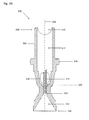
FIG. 2A shows an isometric view of a collector 200. FIG. 2B shows a cross-section view of the collector 200 taken along the line II-II shown in FIG. 2A. Dot-dashed line 202 represents the central or highest-symmetry axis of the collector 200. The collector 200 is similar to the collector 100, except that the collector 200 includes a main body 204 that is more elongated than the main body of the collector 100 in order to accommodate a greater portion of the processing vessel (not shown). The main body 204 includes a first end 206 and a second end 208. A seal may be formed between the second end 208 and an inner wall of the primary vessel to maintain a fluid-tight sealing engagement before, during, and after centrifugation and to inhibit any portion of the suspension flowing between an inner wall of the primary vessel and the main body 204 of the collector 200. The seal may be formed by an interference fit, a grease (such as vacuum grease), an adhesive, an epoxy, by bonding (such as thermal bonding), by welding (such as ultrasonic welding), clamping (such as with a ring or clamp), an insert (such as an O-ring or a collar) that fits between the second end 208 and the inner wall of the primary vessel, or the like.
The first end 206 includes a cavity 212 dimensioned to accept and hold at least a portion of the processing vessel (not shown). The cavity 212 may have a tapered or stepped bottom end 220 on which the processing vessel (not shown) may rest. The first end 206 may also include at least one cut-out 210 to permit proper grip of the processing vessel (not shown) for insertion and removal. The collector 200 funnels the target material from the suspension into an internal concave opening 222 at the second end 208, through a cannula 214, and into a processing vessel (not shown) located within the cavity 212. The cannula 214 may rest on a shelf 224 so that an inner bore of the cannula 214 sits flush with an inner wall of the concave opening 222, as shown in FIG. 2B.
The collector 200 may include a shoulder 216, which extends circumferentially around the main body 204. The shoulder 216 may be larger than the inner diameter of the primary vessel so as to rest on the open end of the primary vessel and, upon applying a lock ring (not shown) to the outside of the primary vessel and the shoulder 216, to inhibit movement of the collector 200 relative to the primary vessel. The lock ring (not shown) applies pressure to the primary vessel along the shoulder 216. The lock ring may be a two-piece ring, a one piece ring wrapping around the full circumference of the primary vessel, or a one piece ring wrapping around less than the full circumference of the primary vessel, such as one-half (½), five-eighths (⅝), two-thirds (⅔), three-quarters (¾), seven-eighths (⅞), or the like. Alternatively, the shoulder 216 may fit within the primary vessel. Alternatively, the shoulder 216 may be a clip, such that the shoulder 216 may include a catch into which the primary vessel may be inserted to inhibit movement of the collector 200 relative to the primary vessel. Alternatively, the shoulder 216 may form an interference fit with the inner wall of the primary vessel around which a seal ring may be placed.
As shown in FIG. 2A, the collector 200 may include at least one window 218 to access the cavity 212 through an inner wall of the main body 204. The at least one window 218 permits an operator to confirm proper placement of the processing vessel (not shown) within the cavity 212. The at least one window 218 also allows fluid discharged from the cannula 214 to flow out of the collector 200 and into a space formed between the collector 200 and the primary vessel (not shown) and above the seal between the second end 208 and the inner wall of the primary vessel.
FIG. 2C shows an isometric view of a collector 230. FIG. 2D shows a cross-section view of the collector 230 taken along the line III-III shown in FIG. 2C. The collector 230 is similar to the collector 200, except that the collector 230 includes a main body 238 including an extension 234 extending away from a first end 232 and a lid 236 to at least temporarily seal an opening 240 within the extension 234. The opening 240 may be in fluid communication with the cavity 212 at the first end 232. The lid 236 may removable, puncturable and resealable (e.g. a flap lid), or puncturable and non-resealable (e.g. a foil lid). The extension 234 may be sized to accept the lid 236 when punctured such that a portion of the lid 236 does not extend into the cavity 212 at the first end 232. Note that the collector 230 does not include the at least one cut-out 210.
The main body can be composed of a variety of different materials including, but not limited to, a ceramic; metals; organic or inorganic materials; and plastic materials, such as polyoxymethylene (“Delrin®”), polystyrene, acrylonitrile butadiene styrene (“ABS”) copolymers, aromatic polycarbonates, aromatic polyesters, carboxymethylcellulose, ethyl cellulose, ethylene vinyl acetate copolymers, nylon, polyacetals, polyacetates, polyacrylonitrile and other nitrile resins, polyacrylonitrile-vinyl chloride copolymer, polyamides, aromatic polyamides (“aramids”), polyamide-imide, polyarylates, polyarylene oxides, polyarylene sulfides, polyarylsulfones, polybenzimidazole, polybutylene terephthalate, polycarbonates, polyester, polyester imides, polyether sulfones, polyetherimides, polyetherketones, polyetheretherketones, polyethylene terephthalate, polyimides, polymethacrylate, polyolefins (e.g., polyethylene, polypropylene), polyallomers, polyoxadiazole, polyparaxylene, polyphenylene oxides (PPO), modified PPOs, polystyrene, polysulfone, fluorine containing polymer such as polytetrafluoroethylene, polyurethane, polyvinyl acetate, polyvinyl alcohol, polyvinyl halides such as polyvinyl chloride, polyvinyl chloride-vinyl acetate copolymer, polyvinyl pyrrolidone, polyvinylidene chloride, specialty polymers, polystyrene, polycarbonate, polypropylene, acrylonitrite butadiene-styrene copolymer, butyl rubber, ethylene propylene diene monomer; and combinations thereof.
The cannula can be composed of a variety of different materials including, but not limited to, a ceramic; metals; organic or inorganic materials; and plastic materials, such as a polypropylene, acrylic, polycarbonate, or the like; and combinations thereof. The cannula may have a tip along a longitudinal axis of the cannula.
Collector-Processing Vessel System
FIG. 3A shows an exploded view of the example collector 200 and processing vessel 302. FIG. 3B shows a cross-sectional view of the processing vessel 302 inserted into the cavity 212 at the first end 206 of the collector 200 taken along the line IV-IV shown in FIG. 3A. The collector 200 and processing vessel 302 form a collector-processing vessel system 300. The processing vessel 302 may be an Eppendorf tube, a syringe, or a test tube and has a closed end 304 and an open end 306. The open end 306 is sized to receive a cap 308. The cap 308 may be composed of re-sealable rubber or other suitable re-sealable material that can be repeatedly punctured with a needle or other sharp implement to access the contents stored in the processing vessel 302 interior and re-seals when the needle or implement is removed. Alternatively, the processing vessel 302 may also have two open ends that are sized to receive caps. The processing vessel 302 may have a tapered geometry that widens or narrows toward the open end 306; the processing vessel 302 may have a generally cylindrical geometry; or, the processing vessel 302 may have a generally cylindrical geometry in a first segment and a cone-shaped geometry in a second segment, where the first and second segments are connected and continuous with each other. Although at least one segment of the processing vessel 302 has a circular cross-section, in other embodiments, the at least one segment can have elliptical, square, triangular, rectangular, octagonal, or any other suitable cross-sectional shape. The processing vessel 302 can be composed of a transparent, semitransparent, opaque, or translucent material, such as plastic or another suitable material. The processing vessel includes a central axis 314, which when inserted into the cavity 212 is coaxial with the central axis 202 of the collector 200. The processing vessel 302 may also include a plug 310 at the closed end 304 to permit the introduction of the target material or to exchange the target material with a displacement fluid 312. The closed end 304 may be threaded to provide for a threaded connection with a threaded cavity 212 of the collector 200. The processing vessel 302 may be composed of glass, plastic, or other suitable material.
The plug 310 may be composed of re-sealable rubber or other suitable re-sealable material that can be repeatedly punctured with a needle or other sharp implement to access the contents of the processing vessel 302 interior or permit introduction of contents into the processing vessel 302 and re-seals when the needle or implement is removed. The plug 310 may be inserted into the processing vessel 302 such that a seal is maintained between the plug 310 and the processing vessel 302, such as by an interference fit. Alternatively, the plug 310 can be formed in the closed end 304 of the processing vessel 302 using heated liquid rubber that can be shaped while warm or hot and hardens as the rubber cools. An adhesive may be used to attach a plug 310 to the inner wall of the processing vessel can be a polymer-based adhesive, an epoxy, a contact adhesive or any other suitable material for bonding or creating a thermal bond. Alternatively, the plug 310 may be injected into the processing vessel 302. Alternatively, the plug 310 may be thermally bonded to the processing vessel 302.
In the example of FIG. 3B, the cannula 214 has a tapered tip that punctures the plug 310 and extends into an inner cavity of the processing vessel 302 with the shaft of the cannula 214 not extending into the inner cavity of the processing vessel 302. As explained in greater detail below, the inner cavity of the processing vessel 302 holds the target material. The cannula 214 may be covered by a resealable sleeve (not shown) to prevent the target material from flowing out unless the processing vessel 302 is in the cavity 212 to a depth that allows the cannula 214 to just penetrate the processing vessel 302. The resealable sleeve (not shown) covers the cannula 214, is spring-resilient, can be penetrated by the cannula 214, and is made of an elastomeric material capable of withstanding repeated punctures while still maintaining a seal.
As shown in FIGS. 3A-3B, the processing vessel 302 may be loaded with a displacement fluid 312 prior to insertion into the collector 200. The displacement fluid 312 displaces the target material, such that when the collector 200 and processing vessel 302 are inserted into the primary vessel (not shown) including the target material, and the collector, processing vessel, and primary vessel undergo centrifugation, the displacement fluid 312 flows out of the processing vessel 302 and into the primary vessel, and, through displacement, such as through buoyant displacement (i.e. lifting a material upwards), pushes the target material through the cannula 214 and into the processing vessel 302.
The displacement fluid 312 has a greater density than the density of the desired target material of the suspension (the density may be greater than the density of a subset of suspension fractions or all of the suspension fractions) and is inert with respect to the suspension materials. For example, the displacement fluid may have a density that is approximately 0.0001 to approximately 0.1 g/cm3 greater than the density of the desired target material. The displacement fluid 312 may be miscible or immiscible in the suspension fluid. Examples of suitable displacement fluids include, but are not limited to, solution of colloidal silica particles coated with polyvinylpyrrolidone (e.g. Percoll), polysaccharide solution (e.g. Ficoll), iodixanol (e.g. OptiPrep), an organic solvent, a liquid wax, an oil, a gas, and combinations thereof; olive oil, mineral oil, silicone oil, immersion oil, mineral oil, paraffin oil, silicon oil, fluorosilicone, perfluorodecalin, perfluoroperhydrophenanthrene, perfluorooctylbromide, and combinations thereof; organic solvents such as 1,4-Dioxane, acetonitrile, ethyl acetate, tert-butanol, cyclohexanone, methylene chloride, tert-Amyl alcohol, Cert-Butyl methyl ether, butyl acetate, hexanol, nitrobenzene, toluene, octanol, octane, propylene carbonate, tetramethylene sulfones, and ionic liquids; polymer-based solutions; surfactants; perfluoroketones, such as perfluorocyclopentanone and perfluorocyclohexanone, fluorinated ketones, hydrofluoroethers, hydrofluorocarbons, perfluorocarbons, perfluoropolyethers, silicon and silicon-based liquids, such as phenylmethyl siloxane; and combinations thereof.
The processing vessel 302 may also include a processing solution (not shown) to effect a transformation on the target material when the target material enters the processing vessel 302. The processing solution (not shown) may be a preservative, a cell adhesion solution, a dye, or the like. Unlike the displacement fluid 312, most, if not all, of the processing solution (not shown) remains within the processing vessel 302 upon centrifugation, thereby effecting the transformation on the target material in one manner or another (i.e. preserving, increasing adhesion properties, or the like). The processing solution (not shown) may be introduced as a liquid or as a liquid contained in a casing. The casing may be dissolvable in an aqueous solution but not in the displacement fluid 312 (such as gel cap); or, the casing may be breakable, such that the casing breaks when the processing vessel 302 is shaken in a vortex mixer. Additionally, more than one processing solution may be used.
The processing vessel 302 may include a flexible cap that can be pushed to dispense a pre-determined volume therefrom and onto a substrate, such as a slide or a well plate. The cap 308 may be flexible or the cap 308 may be removed and the flexible cap inserted into the open end 306. Alternatively, the processing vessel 302 may be attached to (i.e. after accumulating the target material) or may include a dispenser, which is capable of dispensing a pre-determined volume of target material from the processing vessel 302 onto another substrate, such as a microscope slide. The dispenser may repeatedly puncture the re-sealable cap 308 or compress the material within the processing vessel 302 to withdraw and dispense the pre-determined volume of target material onto the substrate. Alternatively, the cap 308 may be removed and the dispenser (not shown) may be inserted directly into the processing vessel 302 to dispense the buffy coat-processing solution mixture.
Collector-Canopy System
FIG. 4A shows an exploded view of the example collector 200 and a canopy 402. FIG. 4B shows a cross-sectional view of the canopy 402 inserted into the cavity 212 of the collector 200 taken along the line V-V shown in FIG. 4A. The collector 200 and canopy 402 form a collector-canopy system 400. The canopy 402 is similar to the processing vessel 302, except that the canopy has a second open end 404. When the collector-canopy system 400 is inserted into the primary vessel, some fluid within the primary vessel, such as a portion of the suspension, a portion of a suspension fraction, a portion of a clearing fluid, or the like, may be discharged through the cannula 214. The canopy 402 inhibits a portion of the fluid in the primary vessel that may be discharged through the cannula 214 from escaping from the opening of the first end 206 of the collector 200. The discharged fluid, having been blocked by the canopy 402, flows out of the second open end 404, and out of the window 218. Dashed lines 406 show fluid flow as the fluid is discharged through the cannula 214 and retained by the canopy 402.
Alternatively, when the collector 230 is used, the lid 236 of the collector 230 inhibits a portion of the fluid in the primary vessel that may be discharged through the cannula 214 from escaping from the opening of the first end 206 of the collector 200 in a manner similar to that of the canopy 402.
Sealing Ring
FIG. 5A shows an isometric view of a sealing ring 500. FIG. 5B shows a top down view of the sealing ring 500. Dot-dashed line 502 represents the central or highest-symmetry axis of the sealing ring 500. The sealing ring 500 includes an inner wall 504, an outer wall 506, and a cavity 508. In FIG. 5B, RIW represents the radial distance from the center of the sealing ring 500 to the inner wall 504, and ROW represents the radial distance from the center of the sealing ring 500 to the outer wall 506. The sealing ring 500 is configured to fit around a primary vessel, such as a tube. The cavity 508 is sized and shaped to receive the primary vessel. The sealing ring 500 may be tightened, such that the size of the cavity 508 and the radii of the inner and outer walls 504 and 506 are reduced by circumferentially applying an approximately uniform, radial force, such as the radial force created by a clamp, around the outer wall 506 directed to the central axis 502 of the sealing ring 500. When the sealing ring 500 is tightened around the primary vessel, the uniform force applied to the sealing ring 500 is applied to the primary vessel, thereby causing the primary vessel to constrict. When the radial force is removed from the sealing ring 500, the sealing ring 500 remains tightened and in tension around the primary vessel.
The sealing ring may be any shape, including, but not limited to, circular, triangular, or polyhedral. FIG. 5C shows an isometric view of a sealing ring 510. FIG. 5D shows a top down view of the sealing ring 510. Sealing ring 510 is similar to sealing ring 500, except sealing ring 510 is polyhedral. Dot-dashed line 512 represents the central or highest-symmetry axis of the sealing ring 510. The sealing ring 510 includes an inner wall 514, an outer wall 516, and a cavity 518. The sealing ring may be composed of a metal, such as brass, a polymer, or combinations thereof.
Alternatively, as shown in FIG. 5E, a sealing ring 520 may be composed of a piezoelectric material. FIG. 5F shows a top down view of the sealing ring 520. Dot-dashed line 522 represents the central or highest-symmetry axis of the sealing ring 520. The sealing ring 520 may be connected to an electric potential source 528, such as a battery, via a first lead 524 and a second lead 526. The electric potential source 528 creates a mechanical strain that causes the sealing ring 520 to tighten (i.e. sealing ring 520 radii decrease). The sealing ring 520 includes an inner wall 530, an outer wall 532, and a cavity 534. In FIG. 5F, RIW represents the radial distance from the center of the sealing ring 520 to the inner wall 530, and ROW represents the radial distance from the center of the sealing ring 520 to the outer wall 532. Alternatively, the sealing ring 520 may be in a naturally tightened stated. When applying the electric potential the sealing ring 520 expands. Alternatively, a portion of the sealing ring may be composed of the piezoelectric material, such that the piezoelectric portion acts as an actuator to cause the other portion of the sealing ring to tighten and apply the substantially uniform circumferential pressure on the primary vessel, thereby constricting the primary vessel to form the seal.
FIG. 5G shows an isometric view of a sealing ring 540. The sealing ring includes an adjustment mechanism 548 to adjust the inner diameter RID. The collapsible ring includes a first end 542 and a second end 546, the first and second ends 542 and 546 being joined by a band portion 544. The first and second ends 542 and 546 include complementary portions of the adjustment mechanism 548. The adjustment mechanism 548 includes, but is not limited to, a ratchet, tongue and groove, detents, or the like.
The sealing ring may also include a thermal element, such as a heated wire. The thermal element may soften the primary vessel for constriction. Alternatively, the thermal element may melt the primary vessel to provide a more adherent seal. Alternatively, the thermal element may cause the sealing ring to compress, thereby forming a seal between the primary vessel and float.
Sequential Density Fractionation Method
Sequential density fractionation is the division of a sample into fractions or of a fraction of a sample into sub-fractions by a step-wise or sequential process, such that each step or sequence results in the collection or separation of a different fraction or sub-fraction from the preceding and successive steps or sequences. In other words, sequential density fractionation provides individual sub-populations of a population or individual sub-sub-populations of a sub-population of a population through a series of steps. For example, buffy coat is a fraction of a whole blood sample. The buffy coat fraction can be further broken down into sub-fractions including, but not limited to, reticulocytes, granulocytes, lymphocytes/monocytes, and platelets. These sub-fractions may be obtained individually by performing sequential density fractionation.
For the sake of convenience, the methods are described with reference to an example suspension of anticoagulated whole blood. But the methods described below are not intended to be so limited in their scope of application. The methods, in practice, can be used with any kind of suspension. For example, a sample suspension can be urine, blood, bone marrow, cystic fluid, ascites fluid, stool, semen, cerebrospinal fluid, nipple aspirate fluid, saliva, amniotic fluid, vaginal secretions, mucus membrane secretions, aqueous humor, vitreous humor, vomit, and any other physiological fluid or semi-solid. It should also be understood that a target material can be a fraction of a sample suspension, such as buffy coat, a cell, such as ova, fetal material (such as trophoblasts, nucleated red blood cells, fetal red blood cells, fetal white blood cells, fetal DNA, fetal RNA, or the like), or a circulating tumor cell (“CTC”), a circulating endothelial cell, an immune cell (i.e. naïve or memory B cells or naïve or memory T cells), a vesicle, such as an exosome, a liposome, a protein, a nucleic acid, a biological molecule, a naturally occurring or artificially prepared microscopic unit having an enclosed membrane, parasites (e.g. spirochetes, such as Borrelia burgdorferi which cause Lyme disease; malaria-inducing agents), microorganisms, viruses, or inflammatory cells. Additionally, the fetal material may be any biological material that is present in a pregnant female as a result of the pregnancy. Alternatively, the sample may be a biological solid, such as tissue, that has been broken down, such as by collagenase, prior to or after being added to the primary vessel.
For example, target material enrichment is a process by which the target materials are purified relative to non-target material. For example, the target material may be enriched relative to non-target material, thereby having a ratio as low as 1 part target material, such as a single cell, protein, DNA, or the like, to 30,000,000 parts non-target material. Other ratios may include, but at not limited to, as low as approximately 1:25,000,000, 1:15,000,000, 1:10,000,000, 1:5,000,000, 1:1,000,000, 1:250,000, 1:100,000, 1:50,000, 1:25,000, 1:10,000, 1:1,000, 1:100, 1:10, or 1:1.
FIG. 6 shows a flow diagram for an example method for retrieving target material. In block 602, a suspension, such as anticoagulated whole blood, is obtained. In block 604, the whole blood is added to a primary vessel, such as a test tube. A float may also be added to the primary vessel. For the sake of convenience, the methods are described with reference to the float, but the methods described below are not intended to be so limited in their application and may be performed without the float.
FIG. 7A shows an isometric view of an example primary vessel and float system 700. The system 700 includes a primary vessel 702 and a float 704 suspended within whole blood 706. In the example of FIG. 7A, the primary vessel 702 has a circular cross-section, a first open end 710, and a second closed end 708. The open end 710 is sized to receive a cap 712. The primary vessel may also have two open ends that are sized to receive caps, such as the example tube and separable float system 720 shown FIG. 7B. The system 720 is similar to the system 700 except the primary vessel 702 is replaced by a primary vessel 722 that includes two open ends 724 and 726 configured to receive the cap 712 and a cap 728, respectively. The primary vessels 702 and 722 have a generally cylindrical geometry, but may also have a tapered geometry that widens, narrows, or a combination thereof toward the open ends 710 and 724, respectively. Although the primary vessels 702 and 722 have a circular cross-section, in other embodiments, the primary vessels 702 and 722 can have elliptical, square, triangular, rectangular, octagonal, or any other suitable cross-sectional shape that substantially extends the length of the tube. The primary vessels 702 and 722 can be composed of a transparent, semitransparent, opaque, or translucent material, such as plastic or another suitable material. The primary vessels 702 and 722 each include a central axis 718 and 730, respectively. The primary vessel 702 may also include a septum 714, as seen in magnified view 716, at the closed end 708 to permit the removal of a fluid, the suspension, or a suspension fraction, whether with a syringe, a pump, by draining, or the like. The primary vessel 702 may have an inner wall and a first diameter.
The septum 714 may be composed of re-sealable rubber or other suitable re-sealable material that can be repeatedly punctured with a needle or other sharp implement to access the contents of the primary vessel 702 interior and re-seals when the needle or implement is removed. The septum 714 may be inserted into the primary vessel 702 such that a seal is maintained between the septum 714 and the primary vessel 702, such as by an interference fit. Alternatively, the septum 714 can be formed in the openings and/or the bottom interior of the tube using heated liquid rubber that can be shaped while warm or hot and hardens as the rubber cools. An adhesive may be used to attach the septum 714 to the wall of the opening and tube interior and can be a polymer-based adhesive, an epoxy, a contact adhesive or any other suitable material for bonding rubber to plastic or creating a thermal bond. Alternatively, the septum 714 may be thermally bonded to the primary vessel 702.
The float 704 includes a main body, two teardrop-shaped end caps, and support members radially spaced and axially oriented on the main body. Alternatively, the float 704 may not include any support members. Alternatively, the float 704 may include support members which do not engage the inner wall of the primary vessel 702.
In alternative embodiments, the number of support members, support member spacing, and support member thickness can each be independently varied. The support members can also be broken or segmented. The main body is sized to have an outer diameter that is less than the inner diameter of the primary vessel 702, thereby defining fluid retention channels between the outer surface of the main body and the inner wall of the primary vessel 702. The surfaces of the main body between the support members can be flat, curved or have another suitable geometry. The support members and the main body may be a singular structure or may be separate structures.
Embodiments include other types of geometric shapes for float end caps. The top end cap may be teardrop-shaped, dome-shaped, cone-shaped, or any other appropriate shape. The bottom end cap may be teardrop-shaped, dome-shaped, cone-shaped, or any other appropriate shape. In other embodiments, the main body of the float 704 can include a variety of different support structures for separating samples, supporting the tube wall, or directing the suspension fluid around the float during centrifugation. Embodiments are not intended to be limited to these examples. The main body may include a number of protrusions that provide support for the tube. In alternative embodiments, the number and pattern of protrusions can be varied. The main body may include a single continuous helical structure or shoulder that spirals around the main body creating a helical channel. In other embodiments, the helical shoulder can be rounded or broken or segmented to allow fluid to flow between adjacent turns of the helical shoulder. In various embodiments, the helical shoulder spacing and rib thickness can be independently varied. In another embodiment, the main body may include a support member extending radially from and circumferentially around the main body. In another embodiment, the support members may be tapered.
The float 704 can be composed of a variety of different materials including, but not limited to, metals; organic or inorganic materials; ferrous plastics; sintered metal; machined metal; plastic materials and combinations thereof. The primary vessel 702 may have an inner wall and a first diameter. The float 704 can be captured within the primary vessel 702 by an interference fit, such that under centrifugation, an inner wall of the tube expands to permit axial movement of the float 704. When centrifugation stops, the inner wall reduces back to the first diameter to induce the interference fit. Alternatively, the inner wall may not expand and the interference fit may not occur between the float 704 and the primary vessel 702, such that the float moves freely within the tube before, during, or after centrifugation. The end caps of the float may be manufactured as a portion of the main body, thereby being one singular structure, by machining, injection molding, additive techniques, or the like; or, the end caps may be connected to the main body by a press fit, an adhesive, a screw, any other appropriate method by which to hold at least two pieces together, or combinations thereof.
The cap 712 may be composed of a variety of different materials including, but not limited to, organic or inorganic materials; plastic materials; and combination thereof.
Returning to FIG. 6, in block 606, the primary vessel, the float, and the whole blood undergo density-based separation, such as by centrifugation, thereby permitting separation of the whole blood into density-based fractions along an axial position in the tube based on density. FIG. 8 shows an isometric view of the primary vessel and float system 700 having undergone density-based separation, such as by centrifugation. Suppose, for example, the centrifuged whole blood includes three fractions. For convenience sake, the three fractions include plasma, buffy coat, and red blood cells. However, when another suspension undergoes centrifugation, there may be more than, less than, or the same number of fractions, each fraction having a different density. The suspension undergoes axial separation into three fractions along the length the tube based on density, with red blood cells 803 located on the bottom, plasma 801 located on top, and buffy coat 802 located in between, as shown in FIG. 8. The float 704 may have any appropriate density to settle within one of the fractions. The density of the float 704 can be selected so that the float 704 expands the buffy coat 802 between the main body of the float and the inner wall of the primary vessel. The buffy coat 802 can be trapped within an area between the float 704 and the primary vessel 702.
At least one delineation fluid (not shown) may be used to provide further separation between the target material and any non-target material above and/or below the target material. The at least one delineation fluid (not shown) may have a density greater than or less than the target material. For example, when it is desirous to further separate the buffy coat 802 and the red blood cells 803, the delineation fluid may have a density greater than the buffy coat 802 and less than, the red blood cells 803. The at least one delineation fluid (not shown) may be miscible or immiscible with the suspension fluid and inert with respect to the suspension materials. The at least one delineation fluid (not shown) may also provide an area in which to seal the primary vessel 702, because there is greater delineation and separation between the buffy coat 802 and the red blood cells 803. The at least one delineation fluid (not shown) may be used whether or not a float is used. Examples of suitable delineation fluids include, but are not limited to, solution of colloidal silica particles coated with polyvinylpyrrolidone (e.g. Percoll), polysaccharide solution (e.g. Ficoll), iodixanol (e.g. OptiPrep), cesium chloride, sucrose, sugar-based solutions, polymer-based solutions, surfactants, an organic solvent, a liquid wax, an oil, a gas, and combinations thereof; olive oil, mineral oil, silicone oil, immersion oil, mineral oil, paraffin oil, silicon oil, fluorosilicone, perfluorodecalin, perfluoroperhydrophenanthrene, perfluorooctylbromide, and combinations thereof; organic solvents such as 1,4-Dioxane, acetonitrile, ethyl acetate, tert-butanol, cyclohexanone, methylene chloride, tert-Amyl alcohol, tert-Butyl methyl ether, butyl acetate, hexanol, nitrobenzene, toluene, octanol, octane, propylene carbonate, tetramethylene sulfones, and ionic liquids; polymer-based solutions; surfactants; perfluoroketones, such as perfluorocyclopentanone and perfluorocyclohexanone, fluorinated ketones, hydrofluoroethers, hydrofluorocarbons, perfluorocarbons, perfluoropolyethers, silicon and silicon-based liquids, such as phenylmethyl siloxane; and combinations thereof.
FIG. 9 shows a seal being formed to prevent fluids from moving up or down within the primary vessel. The seal also inhibits float movement. The sealing ring 500 exerts circumferential or radial forces on the primary vessel 702, thereby causing the primary vessel 702 to collapse inwardly against the float 704 magnified view 902 shows the sealing ring 500 tightened around the float and primary vessel system 700. The sealing ring 500, having been placed at an interface of the buffy coat 802 and the red blood cells 803, causes the primary vessel 702 to collapse inwardly until a seal is formed between the primary vessel 702 and the float 704. An outer wall of the sealing ring 500 may sit flush with an outer wall of the primary vessel 702; the outer wall of the sealing ring 500 may extend past the outer wall of the primary vessel 702; or, the outer wall of the primary vessel 702 may extend past the outer wall of the sealing ring 500. The sealing ring 500 remains tightened to maintain the seal, which prevents fluids from moving past the seal in any direction. The sealing ring 500 may also remain in tension. Alternatively, the sealing ring 500 may be overtightened and then the force applied to the sealing ring 500 is removed. The sealing ring 500 may expand slightly, though still remains constricted.
To apply the sealing ring 500 and thereby form the seal, a clamp may be used to circumferentially apply a force directed toward the central axis of the primary vessel 702 to the sealing ring 500 and the float and primary vessel system 700. The sealing ring 500 is placed around the float and primary vessel system 700 after the float and primary vessel system 700 have undergone density-based separation, such as by centrifugation. The sealing ring 500 and float and primary vessel system 700 are then placed into the clamp. The clamp may include a shelf to support the sealing ring 500 against the primary vessel 702. Operation of the clamp may be automated or may be performed manually. Alternatively, the clamp may form a seal between the float 704 and primary vessel 702 without the inclusion of the sealing ring 500. Alternatively, a seal may be formed between the float 704 and the primary vessel 702 such as by ultrasonic welding; or by applying heat or a temperature gradient to deform and/or melt the primary vessel 702 to the float 704. For the sake of convenience, the methods are described with reference to the sealing ring, but the methods described below are not intended to be so limited in their application and may be performed without the sealing ring.
When operation of the clamp is automated, a motor causes translation of either a collet, including collet fingers, or a pressure member to cause compression of the collet fingers. The motor may be connected to the collet or the pressure member by a shaft, such as a cam shaft, and one or more gears. A base engages and holds the object. When the collet is driven by the motor, the pressure member remains stationary. When the pressure member is driven by the motor, the collet remains stationary. The clamp may include a release, so as to cause the pressure member to slide off of the collet fingers 904, thereby removing the clamping force.
Alternatively, the clamp may be, but is not limited to, a collet clamp, an O-ring, a pipe clamp, a hose clamp, a spring clamp, a strap clamp, or a tie, such as a zip tie. The clamp may be used without a sealing ring to provide a seal between a float and a tube.
The plasma 801 may be removed from the primary vessel 702, as shown in FIG. 10A, such as by pipetting, suctioning, pouring, or the like. Returning to FIG. 6, in block 608, a clearing fluid may be added to the primary vessel along with a collector-canopy system. FIGS. 10B-10C show a clearing fluid 1002 having a density greater than at least the buffy coat 802 (i.e. may have a density greater than the buffy coat but less than the red blood cells, or may have a density greater than both the buffy coat and the red blood cells, for example) being added to the primary vessel 702. The collector-canopy system 400 may then be added to the primary vessel 702, as shown in FIG. 10D. The second end 208 of the collector 200 forms a seal 1008 with the inner wall of the primary vessel 702 to prevent fluid from flowing around the collector 200 before, during, and after centrifugation. The seal 1008 may be formed between the second end 208 and an inner wall of the primary vessel to maintain a fluid-tight sealing engagement before, during, and after centrifugation and to inhibit any portion of the suspension from being located or flowing between an inner wall of the primary vessel and a main body 204 of the collector 200. The seal may be formed by an interference fit, a grease (such as vacuum grease), an adhesive, an epoxy, thermal bonding, ultrasonic welding, clamping (such as with a ring or clamp), an insert that fits between the second end 208 and the inner wall of the primary vessel, or the like. A lock ring 1004 may be placed over the shoulder 216 of the collector 200 and the open end 710 of the primary vessel 702 to inhibit translation of the collector 200 relative to the primary vessel 702. When the collector-canopy system 400 is inserted, a portion of the clearing fluid 1002 in the primary vessel 702 may be discharged through the cannula 214 and stopped by the canopy 402. The discharged fluid may flow out through the window 218 and into the primary vessel 702, though remaining above the seal between the second end 208 and the inner wall of the primary vessel 702, as seen by the dashed lines 406 in magnified view 1006 which is taken along the line VI-VI.
Returning to FIG. 6, in block 610, sequential density fractionation is performed. Block 610 is also a snapshot of the sequential density fractionation steps. In block 612, an nth processing vessel including an nth displacement fluid is inserted into the collector, such that nth is greater than or equal to first (i.e. second, third, fourth, and so on) as seen in FIG. 10E. Alternatively, the nth displacement fluid may be added to the nth processing vessel after the nth processing vessel has been inserted into the collector. Magnified view 1010, which is a cross-section taken along the line IX-IX, shows an nth displacement fluid 1012 in an nth processing vessel 1014 and the clearing fluid 1002 and the buffy coat 802 in the primary vessel 702.
Returning to FIG. 6, in block 614, system is centrifuged to collect a fraction or sub-fraction and the nth processing vessel is removed. In block 616, the operator determines whether or not the desired fraction or sub-fraction is obtained in each respective processing vessel. When the desired fraction or sub-fraction is obtained, the process may stop as shown in block 618, though the process may continue until all fractions or sub-fractions are obtained. When the desired fraction or sub-fractions is not yet obtained, the process restarts at block 612. Each collected sub-fraction may include at least a portion of the target material, no target material, or both target and non-target material.
The processing vessels may also include a processing solution to effect a change on the respective sub-fractions. Two or more processing vessels and respective displacement fluids may be used depending on the number of fractions or sub-fractions desired for separation and collection. Each successive displacement fluid is denser than the preceding displacement fluid. Furthermore, the displacement fluid to collect the target material has a density greater than the density of the desired target material; for example, the displacement fluid may have a density that is approximately 0.0001 to approximately 0.1 g/cm3 greater than the density of the desired target material. Similarly, each successive fraction or sub-fraction is denser than the preceding fraction or sub-fraction. Once collected, the consecutive sub-fractions may be analyzed, such as for diagnostic, prognostic, research purposes, to determine components characteristics (i.e. a complete blood count), how those characteristics change over time, or the like.
FIG. 10F shows the collector-processing vessel system and the primary vessel 702 undergoing centrifugation. Magnified view 1016, which is a cross-section view taken along the line X-X, shows a snapshot of the exchange of fluids between the primary vessel 702 and the processing vessel 1014. As the clearing fluid 1002, having a greater density than the buffy coat 802, moves down in the primary vessel 702, the buffy coat 802 is cleared from the float 704. As the nth displacement fluid 1012, having a density greater than a first sub-fraction 1018 of the buffy coat 802 but less than the clearing fluid 1002 and the remainder of the buffy coat 802, flows from the processing vessel 302 into the primary vessel 702, the first sub-fraction 1018 moves upwards within the primary vessel 702 through the concave opening 222 and the cannula 214, and into the nth processing vessel 1014. As shown in FIG. 10G, the first sub-fraction 1018 is in the nth processing vessel 1014, while the nth displacement fluid 1012 and the clearing fluid 1002 are in the primary vessel 702. N may be greater than or equal to 1.
The nth processing vessel 1014 including the first sub-fraction 1018 may then be removed from the collector 200 to undergo further processing, analysis, storage, or the like. After removing the nth processing vessel 1014, a processing solution may be added, though the processing solution may have already been in the processing vessel prior to retrieval of the target material. The processing vessel may be shaken, such as by a vortex mixer. The processing solution (not shown), having been added before shaking either in liquid form, in a dissolvable casing, or in a breakable casing, may then mix with the buffy coat to effect a transformation and form a buffy coat-processing solution mixture. The buffy coat-processing solution mixture may then be dispensed onto a substrate, such as a microscope slide.
Subsequent processing vessels and displacement fluids may be used to collect additional sub-fractions of the buffy coat 802 until all sub-fractions are collected or until the desired sub-fraction is collected. Though sequential density fractionation is described as being performed with a float and a sealing ring, sequential density fractionation may be performed without a float, a sealing ring, or both. The following is an example method for performing sequential density fractionation:
    • 1. Add blood and float to tube.
    • 2. Centrifuge to effect a density-based separation of the blood (i.e. plasma, Buffy coat, and red blood cells).
    • 3. Apply sealing ring around the tube and float at a bottom end of the float; clamp.
    • 4. Remove plasma.
    • 5. Add clearing fluid which has a density greater than the density of the target material.
    • 6. Insert collector-processing vessel system, a first processing vessel including a first displacement fluid having a first density.
    • 7. Re-centrifuge.
    • 8. Remove the first processing vessel which now includes a first sub-fraction of the Buffy coat less dense than the first displacement fluid.
    • 9. Insert a second processing vessel into the collector, the second processing vessel including a second displacement fluid having a second density which is greater than the first displacement fluid and less than the clearing fluid.
    • 10. Re-centrifuge.
    • 11. Remove the second processing vessel which now includes a second sub-fraction of the Buffy coat less dense than the second displacement fluid and denser than both the first displacement fluid and the first sub-fraction.
    • 12. Repeat steps 9-11 using successively denser displacement fluids so as to collect successively denser sub-fractions until all desired sub-fractions are obtained.
In other words:
    • 1. inserting an (n−y)th processing vessel into a cavity within the collector,
    • 2. adding an (n−y)th displacement fluid to the (n−y)th processing vessel, the (n−y)th displacement fluid;
    • 3. centrifuging the primary vessel, the collector, and the (n−y)th processing vessel, the (n−y)th displacement fluid to flow into the primary vessel via the collector to displace an (n−y)th sub-fraction of the suspension from the primary vessel into the (n−y)th processing vessel through the collector via the cannula;
    • 4. removing the (n−y)th processing vessel including the (n−y)th sub-fraction from the collector.
      For example, n may be any number greater than or equal to 1 and y may be any number greater than or equal to 0, such as n=2 and y=1. Furthermore, n may be the total number of sub-fractions desired and y=(n−1-number of sub-fractions already collected). Furthermore, an (n+1)th sub-fraction does not include any target material.
After retrieving the target material, the target material may be placed on a substrate for imaging and detection (and subsequent storage for archival purposes). At least one portion of the detected target material may then be removed from the substrate, such as by picking, to undergo further analysis. The isolated target material may be deposited into a PCR tube, a well of a well plate, a slide, or any appropriate substrate or vessel for performing the further analysis. Alternatively, the target material may remain within the processing vessel for storage or analysis purposes.
The target material may be analyzed using any appropriate molecular analysis method or technique, such as extracellular and intracellular analysis including intracellular protein labeling, chromogenic staining, nucleic acid analysis, including, but not limited to, DNA arrays, expression arrays, protein arrays, and DNA hybridization arrays; in situ hybridization (“ISH”—a tool for analyzing DNA and/or RNA, such as gene copy number changes); polymerase chain reaction (“PCR”); reverse transcription PCR; or branched DNA (“bDNA”—a tool for analyzing DNA and/or RNA, such as mRNA expression levels) analysis. Fetal material may undergo further processing to test for such fetal abnormalities including, but not limited to, chromosomal abnormalities (e.g. fetal aneuploidy, Down syndrome, trisomy 13, trisomy 18, or a sex chromosome abnormality, such as Turner syndrome), smaller sub-chromosomal abnormalities, gender testing, mutational analysis, and rhesus blood type testing. Additionally, fetal material may undergo expression analysis, for example, for placental function, including pre-eclampsia.
These techniques may require fixation, permeabilization, and isolation (such as by a cell picker) of the target material prior to analysis. Some of the intracellular proteins which may be labeled include, but are not limited to, cytokeratin (“CK”), actin, Arp2/3, coronin, dystrophin, FtsZ, myosin, spectrin, tubulin, collagen, cathepsin D, ALDH, PBGD, Akt1, Akt2, c-myc, caspases, survivin, p27kip, FOXC2, BRAF, Phospho-Akt1 and 2, Phospho-Erk1/2, Erk1/2, P38 MAPK, Vimentin, ER, PgR, PI3K, pFAK, KRAS, ALKH1, Twist 1, Snail1, ZEB1, Fibronectin, Slug, Ki-67, M30, MAGEA3, phosphorylated receptor kinases, modified histones, chromatin-associated proteins, and MAGE. To fix, permeabilize, or label, fixing agents (such as formaldehyde, formalin, methanol, acetone, paraformaldehyde, or glutaraldehyde), detergents (such as saponin, polyoxyethylene, digitonin, octyl β-glucoside, octyl β-thioglucoside, 1-S-octyl-β-D-thioglucopyrano side, polysorbate-20, CHAPS, CHAPSO, (1,1,3,3-Tetramethylbutyl)phenyl-polyethylene glycol or octylphenol ethylene oxide), or labeling agents (such as fluorescently-labeled antibodies, enzyme-conjugated antibodies, Pap stain, Giemsa stain, or hematoxylin and eosin stain) may be used. Examples of suitable antibodies for fetal material may include, but is not limited to, INSL4, MMP14, MCAM, KCNQ4, CLDN6, F3, Mouse Anti-Trophoblast protein Monoclonal Antibody, annexin IV, HLA-G, FACE1 (Novus), SLC1A5 (Chemicon-International), CAP-18 (Abeam), ARMCX3 (Novus), OR11H4 (Abeam), CLCN6 (Santa Cruz), Human placental lactogen, Folate binding protein, HCG (human chorionic gonadotropin), Placental alkaline phosphatase, CD147, CD71, CD35, and CD47.
A solution containing a fluorescent probe may be used to label the target material, thereby providing a fluorescent signal for identification and characterization. The solution containing the fluorescent probe may be added to the suspension before the suspension is added to the vessel, after the suspension is added to the vessel but before centrifugation, or after the suspension has undergone centrifugation. The fluorescent probe includes a fluorescent molecule bound to a ligand. The target material may have a number of different types of surface markers. Each type of surface marker is a molecule, such an antigen, capable of attaching a particular ligand, such as an antibody. As a result, ligands can be used to classify the target material and determine the specific type of target materials present in the suspension by conjugating ligands that attach to particular surface markers with a particular fluorescent molecule. Examples of suitable fluorescent molecules include, but are not limited to, quantum dots; commercially available dyes, such as fluorescein, FITC (“fluorescein isothiocyanate”), R-phycoerythrin (“PE”), Texas Red, allophycocyanin, Cy5, Cy7, cascade blue, DAPI (“4′,6-diamidino-2-phenylindole”), Hoechst, and TRITC (“tetramethylrhodamine isothiocyanate”); combinations of dyes, such as CY5PE, CY7APC, and CY7PE; and synthesized molecules, such as self-assembling nucleic acid structures. Many solutions may be used, such that each solution includes a different type of fluorescent molecule bound to a different ligand. Furthermore, a nucleus of the target material may have a different size than the nucleuses of the non-target material. Determining nuclear size may aid in differentiating between target and non-target material.
The density of the target material may be increased (such as by attaching a weight to the target material or by having the target material absorb or ingest the weight) or may be decreased (such as by attaching a buoy to the target material or by having the target material absorb or ingest the buoy). The weight or the buoy may be bound to a ligand. The target material may have a number of different types of surface markers. Each type of surface marker is a molecule, such as an antigen, capable of attaching a particular ligand, such as an antibody. As a result, ligands can be selected to attached specifically to the target material to alter the density of the target material. Examples of suitable weights and/or buoys include, but are not limited to beads composed of metal, glass, ceramic, plastic, or combinations thereof. Alternatively, the weight or buoy may be attached to a non-target material to change the density of the non-target material to obtain a purer sample of the target material. Alternatively, the density of the target material may be changed by altering or changing the state of the target material. For example, an immune cell may be activated, thereby causing a change in the density of the activated immune cells. The change in density may occur before collection of the target material into the processing vessel or after collection of the target material into the processing vessel.
The foregoing description, for purposes of explanation, used specific nomenclature to provide a thorough understanding of the disclosure. However, it will be apparent to one skilled in the art that the specific details are not required in order to practice the systems and methods described herein. The foregoing descriptions of specific embodiments are presented by way of examples for purposes of illustration and description. They are not intended to be exhaustive of or to limit this disclosure to the precise forms described. Many modifications and variations are possible in view of the above teachings. The embodiments are shown and described in order to best explain the principles of this disclosure and practical applications, to thereby enable others skilled in the art to best utilize this disclosure and various embodiments with various modifications as are suited to the particular use contemplated. It is intended that the scope of this disclosure be defined by the following claims and their equivalents:

Claims (20)

We claim:
1. A method for collecting target material from a sample, the method comprising the steps of:
inserting a collector into an open end of a primary vessel that contains the sample;
inserting an nth processing vessel into a cavity within the collector,
adding an nth displacement fluid to the nth processing vessel, the nth displacement fluid having a density greater than an nth sub-fraction of a fraction of the sample, the nth sub-fraction including at least a portion of the target material; and
centrifuging the primary vessel, the collector, and the nth processing vessel, the nth displacement fluid to flow into the primary vessel via a cannula of the collector to displace the nth sub-fraction from the primary vessel into the nth processing vessel via the cannula of the collector.
2. The method of claim 1, wherein nth is equal to or greater than 1st.
3. The method of claim 1, further comprising the steps of:
inserting an (n−y)th processing vessel into the cavity within the collector;
adding an (n−y)th displacement fluid to the (n−y)th processing vessel, the (n−y)th displacement fluid having a density greater than an (n−y)th sub-fraction of a fraction of the sample including at a least a portion of the target material;
centrifuging the primary vessel, the collector, and the (n−y)th processing vessel, the (n−y)th displacement fluid to flow into the primary vessel via the cannula of the collector to displace the (n−y)th sub-fraction of the suspension from the primary vessel into the (n−y)th processing vessel through the collector via the cannula of the collector; and
removing the (n−y)th processing vessel including the (n−y)th sub-fraction from the collector,
wherein all of the steps involving the (n−y)th processing vessels are repeated until the nth processing vessel is reached,
wherein n is the total number of sub-fractions desired,
wherein y is (n−1-number of sub-fractions already collected), and
wherein y is greater than 0.
4. The method of claim 3, wherein at least one of the sub-fractions includes the target material.
5. The method of claim 3, wherein at least one of the sub-fractions does not include the target material.
6. The method of claim 3, wherein the (n−y)th displacement fluid has a density that is approximately 0.0001 to approximately 0.1 g/cm3 greater than the (n−y)th sub-fraction.
7. The method of claim 3, wherein an (n+1)th sub-fraction does not include any target material.
8. The method of claim 3, wherein the fraction is buffy coat and wherein the sub-fractions are different portions of the buffy coat.
9. The method of claim 3, wherein at least one of the sub-fractions includes target material and non-target material.
10. The method of claim 3, wherein the (n−y)th displacement fluid is selected from the group consisting of: a solution of colloidal silica particles coated with polyvinylpyrrolidone, a polysaccharide solution, iodixanol, an organic solvent, a liquid wax, an oil, a gas, olive oil, mineral oil, silicone oil, immersion oil, mineral oil, paraffin oil, silicon oil, fluorosilicone, perfluorodecalin, perfluoroperhydrophenanthrene, perfluorooctylbromide, organic solvents, 1,4-Dioxane, acetonitrile, ethyl acetate, tert-butanol, cyclohexanone, methylene chloride, tert-Amyl alcohol, tert-Butyl methyl ether, butyl acetate, hexanol, nitrobenzene, toluene, octanol, octane, propylene carbonate, tetramethylene sulfones, ionic liquids, a polymer-based solution, a surfactant, a perfluoroketone, perfluorocyclopentanone, perfluorocyclohexanone, a fluorinated ketone, a hydrofluoroether, a hydrofluorocarbon, a perfluorocarbon, a perfluoropolyether, silicon, a silicon-based liquid, phenylmethyl siloxane, and combinations thereof.
11. The method of claim 1, wherein the target material is selected from the group consisting of fetal material, at least one circulating tumor cell, at least one circulating endothelial cell, at least one spirochete, at least one immune cell, at least one exosome, and at least one malaria-inducing agent.
12. The method of claim 1, wherein the target material is fetal material and the fetal material is any biological material that is present in a pregnant female as a result of the pregnancy.
13. The method of claim 12, wherein the target material is at least one trophoblast, nucleated red blood cell, fetal red blood cell, fetal white blood cell, fetal nucleus, fetal DNA, or fetal RNA.
14. The method of claim 12, further comprising the step of testing for at least one fetal abnormality.
15. The method of claim 1, wherein the fraction is buffy coat and wherein the sub-fraction is a portion of the buffy coat.
16. The method of claim 1, wherein the sub-fraction includes target material and non-target material.
17. The method of claim 1, wherein at least one analyte of the target material undergoes molecular analysis.
18. The method of claim 1, wherein at least one analyte of the target material is isolated from the remainder of the target material.
19. The method of claim 1, wherein the nth displacement fluid is selected from the group consisting of: a solution of colloidal silica particles coated with polyvinylpyrrolidone, a polysaccharide solution, iodixanol, an organic solvent, a liquid wax, an oil, a gas, olive oil, mineral oil, silicone oil, immersion oil, mineral oil, paraffin oil, silicon oil, fluorosilicone, perfluorodecalin, perfluoroperhydrophenanthrene, perfluorooctylbromide, organic solvents, 1,4-Dioxane, acetonitrile, ethyl acetate, tert-butanol, cyclohexanone, methylene chloride, tert-Amyl alcohol, tert-Butyl methyl ether, butyl acetate, hexanol, nitrobenzene, toluene, octanol, octane, propylene carbonate, tetramethylene sulfones, ionic liquids, a polymer-based solution, a surfactant, a perfluoroketone, perfluorocyclopentanone, perfluorocyclohexanone, a fluorinated ketone, a hydrofluoroether, a hydrofluorocarbon, a perfluorocarbon, a perfluoropolyether, silicon, a silicon-based liquid, phenylmethyl siloxane, and combinations thereof.
20. The method of claim 1, wherein the nth displacement fluid has a density that is approximately 0.0001 to approximately 0.1 g/cm3 greater than the nth sub-fraction.
US14/665,368 2012-11-30 2015-03-23 Apparatus, system, and method for collecting a target material Active US9217697B2 (en)

Priority Applications (5)

Application Number Priority Date Filing Date Title
US14/665,368 US9217697B2 (en) 2012-11-30 2015-03-23 Apparatus, system, and method for collecting a target material
US14/883,071 US9625360B2 (en) 2012-11-30 2015-10-14 Apparatus, system, and method for collecting a target material
US15/019,697 US9513291B2 (en) 2012-11-30 2016-02-09 Apparatus, system, and method for collecting a target material
US15/173,692 US9541481B2 (en) 2012-11-30 2016-06-05 Apparatus, system, and method for collecting a target material
US15/341,131 US10054524B2 (en) 2012-11-30 2016-11-02 Apparatus, system and method for collecting a target material

Applications Claiming Priority (11)

Application Number Priority Date Filing Date Title
US201261732029P 2012-11-30 2012-11-30
US201261745094P 2012-12-21 2012-12-21
US201361791883P 2013-03-15 2013-03-15
US201361818301P 2013-05-01 2013-05-01
US201361869866P 2013-08-26 2013-08-26
US14/090,337 US20140161688A1 (en) 2012-11-30 2013-11-26 Apparatus, system, and method for collecting a target material
US201461935457P 2014-02-04 2014-02-04
US14/266,939 US20140349828A1 (en) 2013-05-01 2014-05-01 Apparatus, system, and method for collecting a target material
US14/495,449 US9039999B2 (en) 2012-11-30 2014-09-24 Apparatus, system, and method for collecting a target material
US14/610,522 US9539570B2 (en) 2012-11-30 2015-01-30 Apparatus, system, and method for collecting a target material
US14/665,368 US9217697B2 (en) 2012-11-30 2015-03-23 Apparatus, system, and method for collecting a target material

Related Parent Applications (3)

Application Number Title Priority Date Filing Date
US14/266,939 Continuation-In-Part US20140349828A1 (en) 2012-11-30 2014-05-01 Apparatus, system, and method for collecting a target material
US14/495,449 Continuation-In-Part US9039999B2 (en) 2012-11-30 2014-09-24 Apparatus, system, and method for collecting a target material
US14/610,522 Continuation-In-Part US9539570B2 (en) 2012-11-30 2015-01-30 Apparatus, system, and method for collecting a target material

Related Child Applications (5)

Application Number Title Priority Date Filing Date
US14/266,939 Continuation-In-Part US20140349828A1 (en) 2012-11-30 2014-05-01 Apparatus, system, and method for collecting a target material
US14/610,522 Continuation-In-Part US9539570B2 (en) 2012-11-30 2015-01-30 Apparatus, system, and method for collecting a target material
US14/883,017 Continuation-In-Part US9509684B1 (en) 2015-10-14 2015-10-14 System and method for resource access with identity impersonation
US14/883,071 Continuation-In-Part US9625360B2 (en) 2012-11-30 2015-10-14 Apparatus, system, and method for collecting a target material
US14/883,701 Continuation-In-Part US20160035624A1 (en) 2012-11-30 2015-10-15 Semiconductor device manufacturing method and semiconductor device thereof

Publications (2)

Publication Number Publication Date
US20150192506A1 US20150192506A1 (en) 2015-07-09
US9217697B2 true US9217697B2 (en) 2015-12-22

Family

ID=53494949

Family Applications (1)

Application Number Title Priority Date Filing Date
US14/665,368 Active US9217697B2 (en) 2012-11-30 2015-03-23 Apparatus, system, and method for collecting a target material

Country Status (1)

Country Link
US (1) US9217697B2 (en)

Cited By (8)

* Cited by examiner, † Cited by third party
Publication number Priority date Publication date Assignee Title
US20160041077A1 (en) * 2012-11-30 2016-02-11 Rarecyte, Inc. Apparatus, system, and method for collecting a target material
WO2020159569A1 (en) 2019-01-31 2020-08-06 Rarecyte, Inc. Spectral edge detection
USD903898S1 (en) 2018-09-24 2020-12-01 Gentueri Inc. Sampling assembly
US10919034B2 (en) 2012-11-30 2021-02-16 Rarecyte, Inc. Apparatus, system, and method for collecting a target material
US11067487B2 (en) 2012-11-30 2021-07-20 Rarecyte, Inc. Apparatus, system, and method for collecting a target material
US11090646B2 (en) 2017-07-27 2021-08-17 Biomerieux, Inc. Isolation tube
US11471889B2 (en) 2018-09-24 2022-10-18 Gentueri Inc. Sample assembly
US11738288B2 (en) 2020-06-29 2023-08-29 Jacques Chammas Automated system and method to isolate specific cells from blood or bone marrow

Families Citing this family (1)

* Cited by examiner, † Cited by third party
Publication number Priority date Publication date Assignee Title
WO2023042070A1 (en) * 2021-09-14 2023-03-23 Stellenbosch University Extraction device assembly

Citations (22)

* Cited by examiner, † Cited by third party
Publication number Priority date Publication date Assignee Title
US3873271A (en) * 1974-01-02 1975-03-25 Exxon Research Engineering Co Method and apparatus for detecting free water in hydrocarbon fuels
US4464254A (en) 1982-06-03 1984-08-07 Porex Technologies, Corp. Device for separating serum from blood sample
US5186824A (en) 1991-09-04 1993-02-16 Large Scale Biology Corporation System for solid phase reactions
US5254312A (en) * 1992-05-18 1993-10-19 Staebler Charles R Apparatus for collecting a blood sample from a sealed tube
US5275933A (en) 1992-09-25 1994-01-04 The Board Of Trustees Of The Leland Stanford Junior University Triple gradient process for recovering nucleated fetal cells from maternal blood
US5282981A (en) 1992-05-01 1994-02-01 E. I. Du Pont De Nemours And Company Flow restrictor-separation device
US5393674A (en) 1990-12-31 1995-02-28 Levine Robert A Constitutent layer harvesting from a centrifuged sample in a tube
US5489386A (en) 1994-01-31 1996-02-06 Applied Imaging Density gradient medium for the separation of cells
WO1997012681A1 (en) * 1995-10-02 1997-04-10 Analyte Diagnostics, Inc. Sample collection, recovery and dispensing device for saliva
US5840502A (en) 1994-08-31 1998-11-24 Activated Cell Therapy, Inc. Methods for enriching specific cell-types by density gradient centrifugation
US5866071A (en) 1996-03-06 1999-02-02 National Science Council Centrifuge tube with a built-in small tubing for separation following density gradients centrifugation
US5962237A (en) 1996-04-05 1999-10-05 The Johns Hopkins University School Of Medicine Method of enriching rare cells
US20040038356A1 (en) 2000-11-22 2004-02-26 Hakan Pertoft Step-wise process to recover or eliminate biological substances by flotation from underlayered colloidal medium
US20040247487A1 (en) 2001-03-02 2004-12-09 Pierre Commercon Means for extracting products to be analysed and applications thereof in diagnosis and analysis
US20050014273A1 (en) * 2001-08-29 2005-01-20 Dahm Michael Werner Method and device for preparing a sample of biological origin in order to determine at least one constituent contained therein
US20070272612A1 (en) 2006-05-26 2007-11-29 Marcus Joseph Horn Method for the fractionation and separation of particles by step-wise gradient density extraction
US20110124106A1 (en) 2008-07-31 2011-05-26 Ge Healthcare Bio-Sciences Ab Separation device
US20110251041A1 (en) * 2010-04-12 2011-10-13 Biomet Biologics, Llc Method and Apparatus for Separating a Material
US8110393B2 (en) 2007-03-23 2012-02-07 Beckman Coulter, Inc. Method and apparatus for separating and harvesting cells from a whole blood sample
US8278118B2 (en) 2006-05-26 2012-10-02 Prospect Biosystems, Inc. Method for the fractionation and separation of particles by step-wise gradient density extraction
US20130072402A1 (en) 2010-08-20 2013-03-21 Japan Advanced Institute Of Science And Technology Method for collecting nucleated red blood cells via density-gradient centrifugation utilizing changes in blood cell density
US20130280693A1 (en) 2010-08-20 2013-10-24 President and Fellows of Harvard College a University Density-based separation of biological analytes using multiphase systems

Patent Citations (24)

* Cited by examiner, † Cited by third party
Publication number Priority date Publication date Assignee Title
US3873271A (en) * 1974-01-02 1975-03-25 Exxon Research Engineering Co Method and apparatus for detecting free water in hydrocarbon fuels
US4464254A (en) 1982-06-03 1984-08-07 Porex Technologies, Corp. Device for separating serum from blood sample
US5393674A (en) 1990-12-31 1995-02-28 Levine Robert A Constitutent layer harvesting from a centrifuged sample in a tube
US5186824A (en) 1991-09-04 1993-02-16 Large Scale Biology Corporation System for solid phase reactions
US5282981A (en) 1992-05-01 1994-02-01 E. I. Du Pont De Nemours And Company Flow restrictor-separation device
US5254312A (en) * 1992-05-18 1993-10-19 Staebler Charles R Apparatus for collecting a blood sample from a sealed tube
US5275933A (en) 1992-09-25 1994-01-04 The Board Of Trustees Of The Leland Stanford Junior University Triple gradient process for recovering nucleated fetal cells from maternal blood
US5437987A (en) 1992-09-25 1995-08-01 The Board Of Trustees Of The Leland Stanford Junior University Triple gradient process with antibody panning to recover nucleated fetal cells from maternal blood
US5489386A (en) 1994-01-31 1996-02-06 Applied Imaging Density gradient medium for the separation of cells
US5840502A (en) 1994-08-31 1998-11-24 Activated Cell Therapy, Inc. Methods for enriching specific cell-types by density gradient centrifugation
WO1997012681A1 (en) * 1995-10-02 1997-04-10 Analyte Diagnostics, Inc. Sample collection, recovery and dispensing device for saliva
US5866071A (en) 1996-03-06 1999-02-02 National Science Council Centrifuge tube with a built-in small tubing for separation following density gradients centrifugation
US5962237A (en) 1996-04-05 1999-10-05 The Johns Hopkins University School Of Medicine Method of enriching rare cells
US20040038356A1 (en) 2000-11-22 2004-02-26 Hakan Pertoft Step-wise process to recover or eliminate biological substances by flotation from underlayered colloidal medium
US20040247487A1 (en) 2001-03-02 2004-12-09 Pierre Commercon Means for extracting products to be analysed and applications thereof in diagnosis and analysis
US20050014273A1 (en) * 2001-08-29 2005-01-20 Dahm Michael Werner Method and device for preparing a sample of biological origin in order to determine at least one constituent contained therein
US7456024B2 (en) 2001-08-29 2008-11-25 Hexal Pharma Gmbh Method and device for preparing a sample of biological origin in order to determine at least one constituent contained therein
US20070272612A1 (en) 2006-05-26 2007-11-29 Marcus Joseph Horn Method for the fractionation and separation of particles by step-wise gradient density extraction
US8278118B2 (en) 2006-05-26 2012-10-02 Prospect Biosystems, Inc. Method for the fractionation and separation of particles by step-wise gradient density extraction
US8110393B2 (en) 2007-03-23 2012-02-07 Beckman Coulter, Inc. Method and apparatus for separating and harvesting cells from a whole blood sample
US20110124106A1 (en) 2008-07-31 2011-05-26 Ge Healthcare Bio-Sciences Ab Separation device
US20110251041A1 (en) * 2010-04-12 2011-10-13 Biomet Biologics, Llc Method and Apparatus for Separating a Material
US20130072402A1 (en) 2010-08-20 2013-03-21 Japan Advanced Institute Of Science And Technology Method for collecting nucleated red blood cells via density-gradient centrifugation utilizing changes in blood cell density
US20130280693A1 (en) 2010-08-20 2013-10-24 President and Fellows of Harvard College a University Density-based separation of biological analytes using multiphase systems

Cited By (17)

* Cited by examiner, † Cited by third party
Publication number Priority date Publication date Assignee Title
US9625360B2 (en) * 2012-11-30 2017-04-18 Rarecyte, Inc. Apparatus, system, and method for collecting a target material
US20160041077A1 (en) * 2012-11-30 2016-02-11 Rarecyte, Inc. Apparatus, system, and method for collecting a target material
US10919034B2 (en) 2012-11-30 2021-02-16 Rarecyte, Inc. Apparatus, system, and method for collecting a target material
US11067487B2 (en) 2012-11-30 2021-07-20 Rarecyte, Inc. Apparatus, system, and method for collecting a target material
US11850584B2 (en) 2017-07-27 2023-12-26 Biomerieux, Inc. Isolation tube
US11918998B2 (en) 2017-07-27 2024-03-05 BIOMéRIEUX, INC. Assembly comprising a sample collection vessel and a separation container having seal, plunger with seal-piercing point, retainer, and flexible sealing member
US11883818B2 (en) 2017-07-27 2024-01-30 Biomerieux, Inc. Isolation tube
US11090646B2 (en) 2017-07-27 2021-08-17 Biomerieux, Inc. Isolation tube
US11305273B2 (en) 2017-07-27 2022-04-19 Biomerieux, Inc. Isolation tube with a rheological control member and a plunger
US11325117B2 (en) 2017-07-27 2022-05-10 Biomerieux, Inc. Centrifugally separating samples in a container having a seal and containing a plunger for opening the seal
US11383231B2 (en) 2017-07-27 2022-07-12 Biomerieux, Inc. Isolation tube
US11440000B2 (en) 2017-07-27 2022-09-13 Biomerieux, Inc. Isolation tube with an endcap
USD903898S1 (en) 2018-09-24 2020-12-01 Gentueri Inc. Sampling assembly
US11471889B2 (en) 2018-09-24 2022-10-18 Gentueri Inc. Sample assembly
US10753875B1 (en) 2019-01-31 2020-08-25 Rarecyte, Inc. Spectral unmixing of spectroscopic emission images
WO2020159569A1 (en) 2019-01-31 2020-08-06 Rarecyte, Inc. Spectral edge detection
US11738288B2 (en) 2020-06-29 2023-08-29 Jacques Chammas Automated system and method to isolate specific cells from blood or bone marrow

Also Published As

Publication number Publication date
US20150192506A1 (en) 2015-07-09

Similar Documents

Publication Publication Date Title
US9217697B2 (en) Apparatus, system, and method for collecting a target material
CA2922511C (en) A method for collecting a target material comprising using a collector with a cannula and centrifugation
US10919034B2 (en) Apparatus, system, and method for collecting a target material
US9492819B2 (en) Apparatus, system, and method for collecting a target material
US11067487B2 (en) Apparatus, system, and method for collecting a target material
US9945839B2 (en) Apparatus, system, and method for collecting a target material
US10054524B2 (en) Apparatus, system and method for collecting a target material
US9625360B2 (en) Apparatus, system, and method for collecting a target material
US20140349828A1 (en) Apparatus, system, and method for collecting a target material
US9513291B2 (en) Apparatus, system, and method for collecting a target material
US9533303B2 (en) Apparatus, system, and method for collecting a target material
WO2017209780A1 (en) Apparatus, system, and method for collecting target material
EP3074503A1 (en) Apparatus, system, and method for collecting a target material
WO2016122687A1 (en) Apparatus, system, and method for collecting a target material
EP3102665A1 (en) Apparatus, system, and method for collecting a target material
WO2016064639A1 (en) Apparatus, system and method for collecting a target material
WO2017065820A1 (en) Apparatus, system, and method for collecting a target material

Legal Events

Date Code Title Description
AS Assignment

Owner name: RARECYTE, INC., WASHINGTON

Free format text: ASSIGNMENT OF ASSIGNORS INTEREST;ASSIGNORS:U'REN, LANCE;CHOW, JENNIFER;REEL/FRAME:035232/0936

Effective date: 20150311

STCF Information on status: patent grant

Free format text: PATENTED CASE

AS Assignment

Owner name: WESTERN ALLIANCE BANK, AN ARIZONA CORPORATION, CAL

Free format text: SECURITY INTEREST;ASSIGNOR:RARECYTE, INC.;REEL/FRAME:048746/0498

Effective date: 20190329

MAFP Maintenance fee payment

Free format text: PAYMENT OF MAINTENANCE FEE, 4TH YR, SMALL ENTITY (ORIGINAL EVENT CODE: M2551); ENTITY STATUS OF PATENT OWNER: SMALL ENTITY

Year of fee payment: 4

AS Assignment

Owner name: RARECYTE, INC., WASHINGTON

Free format text: RELEASE BY SECURED PARTY;ASSIGNOR:WESTERN ALLIANCE BANK, AN ARIZONA CORPORATION;REEL/FRAME:051445/0343

Effective date: 20191220

MAFP Maintenance fee payment

Free format text: PAYMENT OF MAINTENANCE FEE, 8TH YR, SMALL ENTITY (ORIGINAL EVENT CODE: M2552); ENTITY STATUS OF PATENT OWNER: SMALL ENTITY

Year of fee payment: 8