US9230175B2 - System and method for motion detection in a surveillance video - Google Patents
System and method for motion detection in a surveillance video Download PDFInfo
- Publication number
- US9230175B2 US9230175B2 US14/064,713 US201314064713A US9230175B2 US 9230175 B2 US9230175 B2 US 9230175B2 US 201314064713 A US201314064713 A US 201314064713A US 9230175 B2 US9230175 B2 US 9230175B2
- Authority
- US
- United States
- Prior art keywords
- pixel
- threshold
- value
- thresholds
- processor
- Prior art date
- Legal status (The legal status is an assumption and is not a legal conclusion. Google has not performed a legal analysis and makes no representation as to the accuracy of the status listed.)
- Active, expires
Links
Images


Classifications
-
- G—PHYSICS
- G06—COMPUTING; CALCULATING OR COUNTING
- G06V—IMAGE OR VIDEO RECOGNITION OR UNDERSTANDING
- G06V20/00—Scenes; Scene-specific elements
- G06V20/40—Scenes; Scene-specific elements in video content
- G06V20/49—Segmenting video sequences, i.e. computational techniques such as parsing or cutting the sequence, low-level clustering or determining units such as shots or scenes
-
- G06K9/00765—
-
- G—PHYSICS
- G06—COMPUTING; CALCULATING OR COUNTING
- G06T—IMAGE DATA PROCESSING OR GENERATION, IN GENERAL
- G06T7/00—Image analysis
- G06T7/20—Analysis of motion
- G06T7/254—Analysis of motion involving subtraction of images
-
- G06K9/00543—
-
- G—PHYSICS
- G06—COMPUTING; CALCULATING OR COUNTING
- G06T—IMAGE DATA PROCESSING OR GENERATION, IN GENERAL
- G06T7/00—Image analysis
- G06T7/10—Segmentation; Edge detection
- G06T7/194—Segmentation; Edge detection involving foreground-background segmentation
-
- G06T7/2053—
-
- H—ELECTRICITY
- H04—ELECTRIC COMMUNICATION TECHNIQUE
- H04N—PICTORIAL COMMUNICATION, e.g. TELEVISION
- H04N5/00—Details of television systems
- H04N5/76—Television signal recording
- H04N5/91—Television signal processing therefor
-
- G—PHYSICS
- G06—COMPUTING; CALCULATING OR COUNTING
- G06F—ELECTRIC DIGITAL DATA PROCESSING
- G06F2218/00—Aspects of pattern recognition specially adapted for signal processing
- G06F2218/12—Classification; Matching
- G06F2218/14—Classification; Matching by matching peak patterns
-
- G06T2207/20144—
-
- G—PHYSICS
- G06—COMPUTING; CALCULATING OR COUNTING
- G06T—IMAGE DATA PROCESSING OR GENERATION, IN GENERAL
- G06T2207/00—Indexing scheme for image analysis or image enhancement
- G06T2207/30—Subject of image; Context of image processing
- G06T2207/30232—Surveillance
Definitions
- Disclosed embodiments relate to video monitoring and interpretation by software-aided methodology, and more particularly, to a system and method for improving the utility of video images in systems handling video, such as, for example, for system-interpreted analysis of video images for security purposes.
- Video analytics is an industry term for the automated extraction of information from video.
- Video analytic systems can include a combination of imaging, computer vision and/or machine intelligence applied to real-world problems. Its utility spans several industry segments including video surveillance, retail, and automation.
- Video analytics is distinct from machine vision, machine inspection, and automotive vision.
- Known applications of video analytics can include, for example, detecting suspicious objects and activities for improved security, license plate recognition, traffic analysis for intelligent transportation systems, and customer counting and queue management for retail applications.
- Advantages of automated video surveillance systems include increased effectiveness and lower cost compared to human-operated systems.
- Scene changes can be induced by global or local illumination changes (e.g. sun light, car headlights, street lights), by environmental motion (e.g. blowing debris, shaking trees, running water), or by moving objects (e.g. moving people, cars, and pets).
- illumination changes e.g. sun light, car headlights, street lights
- environmental motion e.g. blowing debris, shaking trees, running water
- moving objects e.g. moving people, cars, and pets.
- Changes in pixel values for a given image can be computed relative to pixel values in a reference image of the same scene.
- a reference image which can be referred to as a background image, generally depicts motionless objects (e.g. buildings, trees, light posts, roads, and parked cars) in a scene.
- illumination and environmental conditions also called clutter motion
- a pixel and/or illumination difference threshold can be used to differentiate static objects from moving objects.
- pixel differences below a threshold can be classified as static objects and pixel differences above the threshold can be classified as moving objects.
- Defining a threshold that accurately separates moving objects from clutter and background motion can be difficult. The more accurate the threshold, the greater the number of pixels corresponding to moving objects can be detected.
- Such an assumption is often violated by drastic and/or non-uniform illumination changes, such as regions of brightness and regions having shadows resulting from, for example, headlights or clouds, respectively.
- Pixel differences associated with such regions can be large, and thus, the regions are classified as moving objects rather than background.
- large pixel differences can be associated with clutter motion (e.g. moving leaves, moving water, fountains). Pixels corresponding to clutter motion often do not correspond to objects of surveillance interest. As such, it is desirable to exclude such regions from the moving object detection.
- blob analysis a surveillance system reacts immediately with a lesser chance for a false alarm (i.e. the surveillance system almost instantly detects a moving object and quickly analyzes its behavior).
- FIG. 1 illustrates the flow of moving object detection. Collectively, these steps can be referred to as background subtraction or background maintenance.
- the initial step can be to build a background image, representing an observed scene (e.g. by acquiring a frame of video input), at 100 . This step can be performed at startup. Steps 2 - 4 can be repeated for each subsequent frame.
- the second step, for each “current” frame can be to determine illumination differences between the current scene image and the background image (e.g., compute a background difference image), at 105 .
- the third step can be to filter out noise (e.g., illumination changes due to static objects) in the background difference image using a pixel difference threshold, at 110 .
- noise e.g., illumination changes due to static objects
- the pixels can then be grouped into blobs, at 115 , and the blobs analyzed, at 120 .
- the background image can be updated with objects that are deemed to be part of the background.
- Each step includes algorithms of different complexity, and the performance of moving object detection is dependent on the performance of such algorithms.
- the ultimate goal of a background subtraction algorithm is to provide accurate moving object detection while maintaining a low rate of false alarms from clutter or illumination changes.
- the performance of the background subtraction algorithm can bound the performance and capabilities of a surveillance system because downstream processing such as recognition and classification depend on the quality and accuracy of blobs. Therefore, there is a constant demand for improving the performance of the background subtraction algorithm.
- Background subtraction is a key step for moving object detection in the presence of either static or dynamic backgrounds. To understand what occurs in a scene, the background subtraction algorithm can be used jointly with object tracking, recognition, classification, behavior analysis, and statistical data collection. Background subtraction is suitable for any application in which background removal is a guide for both reducing the search space and detecting regions of interest for further processing.
- Another approach uses a mixture of Gaussians to model color pixel values in outdoor scenes. Another approach uses not only color information but spatial information as well. That is, each pixel of a current frame is matched to both the corresponding pixel in the background image and pixels neighboring the corresponding pixel. Another approach uses a three-component system: the first component predicts pixel value in a current frame, the second component fills in homogeneous regions of foreground objects, and the third component detects sudden global changes. Yet another approach aggregates the color and texture information for small image blocks.
- the illumination of outdoor scenes cannot easily be controlled. Accordingly, the pixel difference between an image and its corresponding background image cannot be modeled robustly (i.e. the values of the background image can fluctuate drastically, chaotically and non-uniformly). Shadows, glares, reflections and the nature of object surfaces are examples of factors that can cause unpredictable behavior of pixel values and, as such, the pixel difference. Observing that pixel differences corresponding to groups of pixels behave more predictably and/or less chaotically, models were developed to calculate pixel differences by considering groups of pixels around a particular pixel. Such models assume that a pixel difference calculated using spatially close pixels behave more predictably than differences calculated using individual pixels.
- clutter motion e.g., moving leaves on trees
- clutter motion regions can be identified as moving objects and can cause a surveillance system to generate false alarms.
- thresholds depend on the specifics of the surveillance scene, and hence, require tuning during the installation phase. Additionally, different thresholds can be used for different parts of the scene. Such tuning increases the cost of installation without guaranteeing high performance in an uncontrolled outdoor environment. Tuning may require a human to manually re-tune the system under unpredictable weather conditions. The process of choosing thresholds is unpredictable and depends strongly on aspects of background modeling. In systems based on Gaussian modeling, the threshold is uniform and constant for the entire scene. However, in some outdoor scenes each pixel cannot be modeled and updated using the same parametric model.
- a foreground object's motion can occlude edges corresponding to background objects and can induce motion of the edges corresponding to foreground objects. These edges provide strong cues for the detection of foreground objects.
- Human object perception analyzes object edges to determine the object's contour, location, size and three-dimensional (3D) orientation. Once the object contours are analyzed, inner object edges can be analyzed to assist in understanding the object's structure. Similar to human perception, a surveillance system can prioritize the analysis of an object's edges. As such, the surveillance system can analyze edge information first and then analyze the finer grained appearance inside the object boundaries.
- Non-linear weighting facilitates the discrimination of pixel differences owing to illumination from changes induced by object motion.
- Edge detection is performed by a modified Laplacian of Gaussian filter, which preserves the strength of edges. Any edge detection algorithm that does not convert a grayscale (or color) image into a binary image but instead preserves the edge strength maybe used in the proposed approach. Such an edge detection algorithm can be used to localize motion in the image. Automatic threshold updating can keep the background current and can react quickly to localized illumination changes in both space and time.
- Disclosed embodiments for moving object detection can include separating true and false moving object detections, edge detection, and the automatic updating of thresholds.
- disclosed embodiments can include automatic non-linear weighting of pixel differences. Non-linear weighting does not depend on the specifics of a surveillance scene. Additionally, non-linear weighting significantly separates pixel differences corresponding to static objects and pixel differences induced by moving objects. Benefits of non-linear weighting include suppressing noise with a large standard of deviation, simplifying the choice of threshold values, and allowing longer periods of time between the updating of pixel values of the background image.
- a standard technique, based on a Laplacian of Gaussian (LoG) filter to detect edges can be modified such that the strength of edges is preserved in a non-binary image.
- Non-linear weighting together with the modified edge detection technique can accurately discriminate edges of moving objects from edges induced by illumination change, clutter motion, and video compression artifacts.
- two thresholds can be used for each edge image of pixel differences to increase the accuracy in moving object detection. These threshold values can be updated automatically.
- the threshold updating mechanism does not depend on specifics of a surveillance scene, time of day, or weather conditions and is directly controlled by a pixel difference.
- the edge detection of moving objects allows preservation of pixels corresponding to low illumination change and eliminates pixels corresponding to high illumination change.
- FIG. 1 is a flow chart illustrating the flow of moving object detection.
- FIG. 2 is a flow chart illustrating a method for moving object detection, according to an embodiment.
- FIGS. 3A and 3B show a non-smoothed and smoothed image, respectively.
- FIG. 4A shows a smoothed background image
- FIG. 4B shows a smoothed subsequent image of the same scene as in FIG. 4A .
- FIG. 5A illustrates an absolute Altitude Image Difference between the images of FIGS. 4A and 4B .
- FIG. 5B illustrates the application of a universal threshold to the image of FIG. 5A .
- FIGS. 6A and 6B show the image of FIG. 5A smoothed with a Gaussian kernel using two different values for sigma.
- FIG. 7A shows an image produced by multiplying the pixel values of the images of FIGS. 5A and 6A .
- FIG. 7B shows an image produced by convolution of the image of FIG. 7A using a Laplacian of Gaussian kernel.
- FIG. 8 illustrates a convolution using a Laplacian of Gaussian kernel.
- FIGS. 9A and 9B show images produced by the application of a low threshold and a high threshold, respectively, to the image of FIG. 7B .
- FIG. 10A shows an image produced by the combination of FIGS. 9A and 9B .
- FIG. 10B shows an image produced by filling the blobs in the image of FIG. 10A .
- FIGS. 11A and 11B show values of an adaptive Current Low and High Threshold, respectively, for each pixel in an image.
- FIGS. 12A and 12B show values of an adaptive Base Low and High Threshold, respectively, for each pixel in an image.
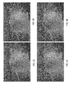
- FIGS. 13-16 compare the application of the GMM method and a method according to a disclosed embodiment to four sets of images.
- Disclosed embodiments may be used in systems and schemes for video handling, motion segmentation, moving object detection, moving object classification, moving object recognition, analysis of changes in video or still images, understanding a surveillance scene or regions of interest in a video or sequence of still images, video synchronization based on detection of similar motion or changes in different videos or sequences of images.
- Disclosed embodiments may be used for improving the utility of video images in various kinds of systems that use video, such as, for example, systems-interpreted analysis of video images for security purposes, object detection, classification and recognition, analysis of changes in the video or still images, understanding surveillance scenes or regions of interest in video or sequences of images, video synchronization based on motion or detecting similar changes in video captured by different cameras.
- video scenes can be captured and then segmented according to the presence of objects or subjects of interest, such as persons or vehicles.
- foreground objects can be any structure or any portion of a structure of a target of interest in a scene.
- a foreground object can be a human, an animal, a human-made good, a structure, a vehicle and/or the like.
- FIG. 2 is a flow chart illustrating an embodiment of a moving object detection method.
- Steps 200 and 205 involve smoothing an image. Smoothing suppresses noise by enforcing the constraint that a pixel should look like its neighbors.
- Image smoothing is the process of replacing a pixel value with a weighted average value of its neighboring pixels.
- the Gaussian kernel is used as a model for smoothing noise caused by small illumination change. See e.g., D. A. Forsyth and J. Ponce, Computer Vision: A Modern Approach, the disclosure of which is incorporated herein by reference.
- the standard of deviation (sigma) of a Gaussian kernel controls the degree of smoothing.
- an image can be smoothed with two Gaussian kernels of the same size with different values of the standard of deviation, sigma. In other embodiments, any other method to smooth the image can be used.
- FIGS. 3A and 3B show a non-smoothed and smoothed image, respectively, with the sharpness of the smoothed image in FIG. 3B being less than the sharpness of the non-smoothed image in FIG. 3A .
- Image smoothing is also used in step 215 , as described in further detail herein.
- the first step in the disclosed background subtraction method is to initialize the background.
- an input frame is smoothed with a Gaussian kernel using an appropriate value for the standard of deviation (sigma), s 1 , to produce an initial background image, also referred to as the Altitude Background Image or AltBackIm.
- the image resolution can be either modified or preserved.
- the very first frame is considered to be a background image.
- FIG. 4A shows an example of a smoothed background image, AltBackIm.
- a current frame or image is obtained and smoothed.
- the current frame can be smoothed with the Gaussian kernel with an appropriate value of sigma, s 2 .
- the value of sigma s 2 can be the same as the value of sigma s 1 .
- sigma s 2 can have a value different from the value of sigma s 1 .
- the smoothed image can be denoted as CurImSmoothed.
- An example of a smoothed current image is shown in FIG. 4B , which shows the same scene as in FIG. 4A , but includes a car moving through the scene.
- step 210 of FIG. 2 the difference between the background image and the current image is calculated. Similarly stated, the value of each pixel in the background image is subtracted from the value of a corresponding pixel (i.e., a pixel in the same location and/or with the same coordinate value) in the current image.
- this difference is an absolute Altitude Image Difference, or AID, between AltBackIm (e.g., FIG. 4A ) and CurImSmoothed (e.g., FIG. 4B ).
- An example of an AID, based on the images shown in FIGS. 4A and 4B is shown in FIG. 5A . At this step, applying a threshold to the AID does not effectively differentiate true changes from false ones.
- FIG. 5B shows foreground pixels after applying a fixed threshold to all pixels of the AID ( FIG. 5A ). Besides pixels corresponding to the moving car, some background pixels were also detected as foreground. Any resulting image of such algebraic operations, which include at least the algebraic difference between the background image and any given image, should be considered as one of the forms of AID contemplated by this disclosure.
- the AID is smoothed with the Gaussian kernel using two different values for sigma, s 3 and s 4 .
- the value of sigma s 3 and/or the value of sigma s 4 can be the same as the value of sigma s 1 and/or the value of sigma s 2 .
- sigma s 3 and/or sigma s 4 can have a value different from the value of sigma s 1 and/or the value of sigma s 2 .
- the resulting images are denoted as AID_smoothed 1 and AID_smoothed 2 , respectively.
- this step emulates temporal smoothing.
- a real moving object corresponds to a blob in the background difference with relatively high pixel difference values distributed across the entire blob.
- Smoothing the background difference disperses the noise of high pixel differences among neighboring pixels with lower values and reduces the false detection rate.
- Smoothing parameters control the blob contour and size of the blob to be detected.
- FIGS. 6A and 6 B show the AID of FIG. 5A smoothed with s 1 and s 2 , respectively, where s 1 is less than s 2 . In other embodiments, any type of image smoothing can be used.
- step 220 of FIG. 2 the value of each pixel of the AID_smoothed 1 is multiplied by the value of a corresponding pixel (i.e., a pixel in the same location and/or with the same coordinate value) of the AID_smoothed 2 .
- the product of the multiplication can be denoted as AAID, or Amplified Altitude Image Difference.
- the multiplication of AID_smoothed 1 by AID_smoothed 2 is an automatic non-linear weighting of the background image difference. Compared to the non-weighted AID, the Euclidian distances between true and false changes in AAID are non-linearly (e.g., exponentially) increased, and can therefore be easily separated.
- Computing the AAID transforms the AID into a different domain, in which the high background differences corresponding to false motion detections are better separated from high background differences corresponding to real objects.
- computing AID_smoothed 1 and AID_smoothed 2 improves the AAID
- the AAID image can be defined directly using values of the AID.
- FIG. 7A shows the AAID produced by the multiplication of the AID_smoothed 1 of FIG. 6A and the AID_smoothed 2 of FIG. 6B .
- the pixels corresponding to the moving car are very distinct from the dark background pixels.
- any suitable approach can be used to calculate the AAID.
- the AAID can be calculated by a) multiplying each pixel of the AID with a corresponding pixel of the AID_smoothed 2 (or AID_smoothed 1 ); b) applying a non-linear function, a combination of non-linear functions, or a combination of linear and non-linear functions to each pixel of the AID, transformed AID, or modified AID; and/or c) applying a linear/non-linear combination of the AID and transformed/modified AID.
- the AAID is convolved with a Laplacian of Gaussian (LoG) kernel using an appropriate sigma. For each pixel, the zero crossings in all possible directions are first determined and then an absolute difference for each zero crossing is calculated. The differences can be summed and stored as a pixel value in an image denoted LoG_Im.
- LoG_Im an image denoted in an image denoted LoG_Im.
- the values corresponding to zero crossings are preserved (i.e. the edge strength is preserved) to define a non-binary edge image.
- non-binary edge detection assists the transformation of the AID from the AAID into the LoG_Im, in which threshold tests can be applied to edge strength.
- no association or difference between the edges in LoG_Im and the edges in AltBackIm is used to detect and/or remove constant change in the background (clutter motion), detect moving objects during non-global illumination changes and/or during a relatively long interval between background updates.
- the edges need not be detected in the background or reference images (e.g., AltBackIm).
- the LoG_Im can be stored in a DeltaDif buffer, which contains the last frames of LoG_Im (NumDifFrames).
- the size of the DeltaDif buffer can be defined by the availability of memory.
- the DeltaDif buffer can also be used in updating a threshold in step 245 , as described in further detail herein.
- the background can be updated during a period of little activity when the system has a high confidence that the pixels are background pixels. Such background updating can be a higher priority task than an immediate reaction to a background change.
- any other edge detection method which does not produce a resulting binary image, applied to non-linearly weighted image can be used instead of a Laplacian of Gaussian-based edge detector.
- FIG. 8 An example of the convolution of step 225 is illustrated in FIG. 8 .
- the input, X is a 9 pixel region.
- the kernel is applied to produce the 9 pixel output, Y.
- the calculation of the value of the [0,0] pixel of the output Y is shown in Equation 1, below.
- FIG. 7B An example of the effect of the convolution is shown in FIG. 7B , in which the LoG convolution is applied to the image of FIG. 7A .
- sharp edges correspond to moving objects, while edges corresponding to the water spray cloud behind the car are much less sharp.
- real moving objects define long, solid, bold and/or strong edges, while false detections define short, dashed, and/or weak edges (see e.g., FIG. 9A ).
- a real moving object defines strong connected and non-connected edges in LoG_Im. The number of pixels corresponding to the strong edges and used in the object detection, controls the detection sensitivity and can vary based on the application. To filter out weak edges, low and high threshold tests can be applied to LoG_Im, at 230 .
- the low threshold, LowThreshold preserves the true changes in the background but does not eliminate all false deviations.
- the high threshold, HighThreshold also preserves the true changes while completely or significantly eliminating false changes. Pixels that pass the high threshold test indicate true foreground blobs that also passed the low threshold test.
- the pixels passed through LowThreshold are stored in LoG_Im_LThresh, and pixels passed through HighThreshold are stored in LoG_Im_HThresh.
- pixels having a value greater than or equal to HighThreshold are stored in LoG_Im_HThresh while pixels having a value less than HighThreshold are not stored in LoG_Im_HThresh (e.g., their pixel locations are set to zero). Pixels having a value less than HighThreshold can be said to be removed from LoG_Im_HThresh.
- pixels having a value greater than or equal to LowThreshold are stored in LoG_Im_LThresh while pixels having a value less than LowThreshold are not stored in LoG_Im_LThresh (e.g., their pixel locations are set to zero).
- FIGS. 9A and 9B depicts edges corresponding to moving objects while eliminating edges corresponding to the water cloud.
- foreground pixels are identified by comparing the pixel values at pixel locations in LoG_Im_HThresh with the pixel values at corresponding pixel locations (i.e., a pixel location in the same location and/or with the same coordinate value) in LoG_Im_LThresh. Initially, the pixel locations having values greater than zero in both LoG_Im_HThresh and LoG_Im_LThresh are classified as foreground pixels (e.g., are preserved).
- each pixel location having a value greater than both the HighThreshold (i.e., pixel is stored in LoG_Im_HThresh) and the LowThreshold (i.e., pixel is stored in LoG_Im_HThresh) is classified as a foreground pixel.
- any pixel connected and/or contiguous to the pixels in both LoG_Im_HThresh and LoG_Im_LThresh i.e., those pixels initially classified as foreground pixels
- LoG_Im_HThresh and LoG_Im_LThresh i.e., those pixels initially classified as foreground pixels
- any pixel within LoG_Im_LThresh and contiguous to the pixel location via at least one other pixel in LoG_Im_LThresh is classified as a foreground object.
- a pixel at a first pixel location having coordinates (row 1, column 1) is in both LoG_Im_HThresh and LoG_Im_LThresh (i.e., is initially classified as a foreground pixel)
- a pixel at a second pixel location having coordinates (row 1, column 4) and not in LoG_Im_HThresh but in LoG_Im_LThresh can be classified as a foreground object if a pixel at (row 1, column 2) and a pixel at (row 1, column 3) are both in LoG_Im_LThresh.
- the pixel at the second pixel location can be said to be contiguous and/or connected to the pixel at the first pixel location.
- pixels in LoG_Im_LThresh but not in LoG_Im_HThresh within a given distance (e.g., a certain number of pixels) of a pixel in both LoG_Im_HThresh and LoG_Im_LThresh can be classified as foreground pixels even if they are not contiguous with the pixel in both LoG_Im_HThresh and LoG_Im_LThresh.
- LoG_Im_LThresh and LoG_Im_HThresh Connected and/or contiguous pixels in LoG_Im_LThresh and LoG_Im_HThresh can be grouped into blobs. Similarly stated, pixels from LoG_Im_HThresh vote for foreground blobs in LoG_Im_LThresh. Any blob in LoG_Im_LThresh, which has at least one vote (e.g., at least one pixel in LoG_Im_HThresh), will be preserved as a foreground blob. These foreground pixels create a new image, LoG_Im_Thresh.
- LoG_Im_HThresh is enough to classify an entire blob in LoG_Im_LThresh as a foreground blob.
- This voting scheme can eliminate pixels corresponding to large illumination differences (e.g., changes their value to zero).
- step 240 of FIG. 2 foreground object segmentation is completed.
- the LoG_Im_Thresh image ( FIG. 10A ) stores the foreground blobs.
- the non-zero pixels in LoG_Im_Thresh indicate corresponding pixels in AID_smoothed 2 ( FIG. 6B ) to be processed for filling in the foreground blobs.
- Each row of the indicated foreground blob in AID_smoothed 2 is scanned to find a minimum value, LocalThresh. A pixel in that row is considered a foreground pixel if its value is greater than LocalThresh.
- LocalThresh is a dynamic value, and thus, provides sensitive detection of foreground pixels in AID_smoothed 2 around corresponding foreground blobs in LoG_Im_Thresh ( FIG. 10A ) and low false alarm rate in the rest of AID_smoothed 2 .
- the resulting foreground pixels represent the final result of moving object segmentation, and the final foreground pixel segmentation is denoted as SegImBin.
- FIG. 10B An example is shown in FIG. 10B , which is based on the LoG_Im_Thresh image of FIG. 10A .
- the HighThreshold value is updated.
- the sensitivity of moving object detection is determined by the HighThreshold, the value of which strongly depends on image brightness and the background difference of each pixel, see FIG. 11 .
- Low contrast video and scene illumination require a lower value.
- HighThreshold cannot be fixed and must be adjusted for each pixel at each time instant.
- TmpVal[i][j] For each pixel at index [i][j], a temporary value TmpVal[i][j] is computed based on Equation 2.
- InitialHighThresholdValue is a fixed number for all pixels, for all scenes and adaptation_rate is also a fixed value that controls the speed of change of the HighThreshold.
- a new HighThreshold is computed next by Equation 3, which is the minimum of three numbers. These are a) the current HighThreshold plus HT_Delta, where HT_Delta is the maximum allowed change to the HighThreshold per frame, b) TmpVal [i][j] computed earlier by Equation 2 and c) a fixed number MaxHighThresholdValue.
- MaxHighThreshold can be set sufficiently high such that no non-moving object will be detected.
- the above two rules gradually increase the value of HighThreshold, and immediately reset the value to InitialHighThresholdValue, if the pixel difference between the background image and the current image is below InitialHighThresholdValue.
- the HighThreshold value can be reset to InitialHighThresholdValue gradually over multiple frames. This step is automatic and expands the application of the disclosed method to different environmental conditions.
- both the LowThreshold and the HighThreshold can be updated.
- the background image can be updated approximately every 2500 frames under non-global illumination change (rain, snow, moving tree branches, moving shadows, etc.) and every 10000 frames under smooth global illumination change under 30 frames per second (fps) video capturing speed.
- no feedback from a high level post background difference processing module is used (e.g., tracking, scene learning and understanding, analyzing structure of the background scene, moving object classification, etc.). Accordingly, the method acts as a standalone background subtraction method.
- ForegroundMask a foreground binary mask
- ForegroundMask is the same as SegImBin.
- ForegroundMask is any binary image in which an area of a foreground blob is expanded and/or dilated.
- HiThreshCur and LoThreshCur are selectively updated for pixels, which are indicated as background pixels (e.g., zeros) in ForegroundMask.
- HistoryThreshUpdate is a counter of how many frames a pixel was detected as a background pixel (e.g., zero).
- a pixel is detected as a foreground pixel (e.g., one), the pixel counter is reset to zero. If a pixel is detected as a background pixel for a number of predetermined frames (NumDifFrames) or more, then its HiThreshCur and LoThreshCur can be updated.
- the pixel counter of HistoryThreshUpdate is reset. Additionally, for each background pixel, the pixel counter of HistoryThreshUpdate is incremented by one or any other suitable amount. Pixels whose counter is greater than or equal to NumDifFrames are classified as BckgrAdjPixels. HistoryThreshUpdate directly controls a minimum waiting period (e.g., a number of frames, an amount of time, etc.) for maintaining confidence that a pixel should be classified as a background pixel.
- a minimum waiting period e.g., a number of frames, an amount of time, etc.
- LoThreshBase and HiThreshBase define the lowest possible values of LowThreshold and HighThreshold, respectively, at which noise can be separated from real moving objects.
- the LoThreshBase and HiThreshBase are the default values used for optimum detection of real moving objects. Further reducing these values can cause more noise and false detections.
- the current low and high threshold are set to the corresponding values in LoThreshBase and HiThreshBase, respectively.
- the threshold values are reset to the base values (LoThreshBase and HiThreshBase) to provide optimum moving object segmentation.
- HiThreshCur(BckgrAdjPixels) min(max(HiThreshCur(BckgrAdjPixels) ⁇ hi_delta_decr, max(DeltaDif(BckgrAdjPixels))+hi_delta_incr),MaxHiThresh(BckgrAdjPixels)) Equation 7
- the current threshold values are either increased or decreased, according to the current background image difference.
- rules gradually increase or decrease the current threshold values.
- Gradual increases and/or decreases of the low threshold are controlled by lo_delta_incr and lo_delta_decr, respectively.
- gradual increases and/or decreases of the high threshold are controlled by hi_delta_incr and hi_delta_decr, respectively.
- MaxLoThresh and MaxHiThresh are maximum values for the LoThreshCur and HiThreshCur, respectively.
- LoThreshCur and HiThreshCur will not have values greater than MaxLoThresh and MaxHiThresh, respectively.
- updating the high threshold and low threshold is fully automatic and expands the application of the background subtraction method to various environmental conditions.
- the values of the low and high threshold depend on image brightness and background difference of each pixel.
- FIGS. 11A and 11B illustrate the current low and high threshold for a frame of an image with respect to a background image.
- FIGS. 12A and 12B show the base low and high values at the frame of the image.
- the challenge presented by the examples below is to detect moving objects with a minimum number of false foreground detections under different illumination and weather conditions without any manual system tuning. In other words, for all tests, all parameters of both algorithms were fixed. Frequent updating of the background model in GMM reduces false foreground detection. However, the frequent updating causes holes inside of moving objects and makes it difficult to detect objects that remained in the scene. In the GMM method, a sharp and sudden change in the background is quickly dissolved into a new background but causes an increase in false foreground detections.
- FIGS. 13 , 14 , 15 and 16 Four examples are illustrated, by FIGS. 13 , 14 , 15 and 16 , respectively.
- the first column (on the left) shows the original input frames;
- the second column shows the GMM results with white pixels corresponding to detected foreground pixels;
- the third column shows results by the method disclosed above with white pixels corresponding to detected foreground pixels;
- the fourth column shows the adapted high threshold as a grayscale image, with brighter pixels indicating a higher value for HighThreshold
- the disclosed method performs better than the GMM method.
- a painting is removed from a wall, an event that is desired to be detected.
- the first, second, third, fourth and fifth rows show results corresponding to frames numbered 6600 , 6684 , 6687 , 6690 and 6693 , respectively.
- the trash bucket is merged with the background (column 2), and the absence of the painting is merged into the background (row 5, column 2).
- the presence of trash bucket and the absence of the painting are preserved in the results using the disclosed method (column 3).
- the individual values of the high threshold preserve detection of foreground objects while eliminating shadows on the wall and floor.
- a van approaches a region under surveillance. While the van is parked, a person leaves the van and drops a box on the ground.
- the first, second, third, fourth and fifth rows show results corresponding to frames numbered 5619 , 5627 , 5635 , 5643 and 5649 , respectively.
- GMM takes approximately 30 frames (1 second in real time) to merge a dropped box with the background model.
- the disclosed method (column 3) preserved the parked van and the dropped box as foreground objects.
- the last column shows the different values of the high threshold computed continuously from frame 1 .
- the bright satellite antennas caused large illumination noise (right top corner of the image), which are eliminated by the high adaptive threshold.
- a car moves towards the camera.
- the first, second, third, fourth and fifth rows show results corresponding to frames numbered 560 , 570 , 580 , 590 and 600 , respectively.
- the amount of light reflecting from the car's surface increases as the car moves toward the camera.
- the reflecting light causes a change in the camera iris which in turn causes all pixel values of the camera image to change.
- Such a change increases the number of false foreground detections.
- the false foreground detections which are illustrated in column 3, do not occupy the whole image and are grouped in distinct objects.
- the fourth column illustrates a gradual automatic increase of the high threshold.
- the large shadow area caused by van is visible in each frame (column 1).
- the adaptive high threshold used by the disclosed method completely suppresses the shadow (column 3).
- background subtraction results using the GMM are compared to the disclosed method in a scene during a rainstorm.
- the first, second, third, fourth and fifth rows show results corresponding to frames numbered 4366 , 4367 , 4368 , 4375 and 4471 , respectively.
- the first three rows illustrate results during a flash of lightning.
- the fourth row illustrates the result of another flash of lightning occurring just after the first one.
- the last row shows moving car detection while a rain drop falls very close to the camera lens and with the wind causing clutter motion of the tree branches.
- the disclosed method did not detect any pixels as foreground (rows 2,3,4 and column 3). The moving car is detected better by the disclosed method than by the GMM method (row 5).
- the wet road and tree leaves are more sensitive to illumination and caused more false foreground detections (column 2).
- the adaptive high threshold eliminated all false detections and preserved the real foreground object (column 3).
- the second row shows the moment of lightning.
- the GMM is very sensitive to sudden illumination change, and almost the whole image was detected as a moving object.
- the proposed algorithm is very robust to this type of illumination change.
- Some embodiments described herein relate to a computer storage product with a computer-readable medium (also can be referred to as a processor-readable medium) having instructions or computer code thereon for performing various computer-implemented operations.
- the media and computer code also can be referred to as code
- Examples of computer-readable media include, but are not limited to: magnetic storage media such as hard disks, floppy disks, and magnetic tape; optical storage media such as Compact Disc/Digital Video Discs (CD/DVDs), Compact Disc-Read Only Memories (CD-ROMs), and holographic devices; magneto-optical storage media such as optical disks; carrier wave signal processing modules; and hardware devices that are specially configured to store and execute program code, such as Application-Specific Integrated Circuits (ASICs), Programmable Logic Devices (PLDs), and Read-Only Memory (ROM) and Random-Access Memory (RAM) devices.
- ASICs Application-Specific Integrated Circuits
- PLDs Programmable Logic Devices
- RAM Random-Access Memory
- Examples of computer code include, but are not limited to, micro-code or micro-instructions, machine instructions, such as produced by a compiler, code used to produce a web service, and files containing higher-level instructions that are executed by a computer using an interpreter.
- embodiments may be implemented using Java, C++, or other programming languages (e.g., object-oriented programming languages) and development tools.
- Additional examples of computer code include, but are not limited to, control signals, encrypted code, and compressed code.
Abstract
Description
AAID(i,j)=AID_smoothed—1(i,j)*AID_smoothed2(i,j),
-
- where i and j are pixel coordinates.
AAID(i,j)=ƒ(AID(i,j)),
-
- where ƒ is a non-linear function.
TmpVal[i][j]=max(InitialHighThresholdValue,adaptation_rate*AID_smoothed2[i][j])
HighThreshold=min(HighThreshold+HT_Delta,TmpVal[i][j],MaxHighThresholdValue)
LoThreshBase(BckgrAdjPixels)=median(DeltaDif(BckgrAdjPixels))+
HiThreshBase(BckgrAdjPixels)=median(DeltaDif(BckgrAdjPixels))+
LoThreshCur(BckgrAdjPixels)=min(max(LoThreshCur(BckgrAdjPixels)−lo_delta_decr, DeltaDif(BckgrAdjPixels)+lo_delta_incr),MaxLoThresh(BckgrAdjPixels))
HiThreshCur(BckgrAdjPixels)=min(max(HiThreshCur(BckgrAdjPixels)−hi_delta_decr, max(DeltaDif(BckgrAdjPixels))+hi_delta_incr),MaxHiThresh(BckgrAdjPixels))
Claims (19)
Priority Applications (1)
| Application Number | Priority Date | Filing Date | Title |
|---|---|---|---|
| US14/064,713 US9230175B2 (en) | 2009-04-22 | 2013-10-28 | System and method for motion detection in a surveillance video |
Applications Claiming Priority (3)
| Application Number | Priority Date | Filing Date | Title |
|---|---|---|---|
| US17171009P | 2009-04-22 | 2009-04-22 | |
| US12/765,199 US8571261B2 (en) | 2009-04-22 | 2010-04-22 | System and method for motion detection in a surveillance video |
| US14/064,713 US9230175B2 (en) | 2009-04-22 | 2013-10-28 | System and method for motion detection in a surveillance video |
Related Parent Applications (1)
| Application Number | Title | Priority Date | Filing Date |
|---|---|---|---|
| US12/765,199 Division US8571261B2 (en) | 2009-04-22 | 2010-04-22 | System and method for motion detection in a surveillance video |
Publications (2)
| Publication Number | Publication Date |
|---|---|
| US20140198257A1 US20140198257A1 (en) | 2014-07-17 |
| US9230175B2 true US9230175B2 (en) | 2016-01-05 |
Family
ID=43011473
Family Applications (2)
| Application Number | Title | Priority Date | Filing Date |
|---|---|---|---|
| US12/765,199 Active 2031-12-08 US8571261B2 (en) | 2009-04-22 | 2010-04-22 | System and method for motion detection in a surveillance video |
| US14/064,713 Active 2030-06-20 US9230175B2 (en) | 2009-04-22 | 2013-10-28 | System and method for motion detection in a surveillance video |
Family Applications Before (1)
| Application Number | Title | Priority Date | Filing Date |
|---|---|---|---|
| US12/765,199 Active 2031-12-08 US8571261B2 (en) | 2009-04-22 | 2010-04-22 | System and method for motion detection in a surveillance video |
Country Status (2)
| Country | Link |
|---|---|
| US (2) | US8571261B2 (en) |
| WO (1) | WO2010124062A1 (en) |
Cited By (1)
| Publication number | Priority date | Publication date | Assignee | Title |
|---|---|---|---|---|
| US20160171852A1 (en) * | 2014-12-12 | 2016-06-16 | Andy Lin | Real-time video analysis for security surveillance |
Families Citing this family (65)
| Publication number | Priority date | Publication date | Assignee | Title |
|---|---|---|---|---|
| US6940998B2 (en) | 2000-02-04 | 2005-09-06 | Cernium, Inc. | System for automated screening of security cameras |
| US7956735B2 (en) | 2006-05-15 | 2011-06-07 | Cernium Corporation | Automated, remotely-verified alarm system with intrusion and video surveillance and digital video recording |
| TWI323434B (en) * | 2006-11-30 | 2010-04-11 | Ind Tech Res Inst | Method of object segmentation for video |
| US8804997B2 (en) * | 2007-07-16 | 2014-08-12 | Checkvideo Llc | Apparatus and methods for video alarm verification |
| US8204273B2 (en) | 2007-11-29 | 2012-06-19 | Cernium Corporation | Systems and methods for analysis of video content, event notification, and video content provision |
| JP5218168B2 (en) * | 2009-03-11 | 2013-06-26 | ソニー株式会社 | Imaging device, moving object detection method, moving object detection circuit, program, and monitoring system |
| US8571261B2 (en) | 2009-04-22 | 2013-10-29 | Checkvideo Llc | System and method for motion detection in a surveillance video |
| US20100283857A1 (en) * | 2009-05-05 | 2010-11-11 | Honeywell International Inc. | Event based dynamic change in video quality parameters of network cameras |
| US20110234829A1 (en) * | 2009-10-06 | 2011-09-29 | Nikhil Gagvani | Methods, systems and apparatus to configure an imaging device |
| US20110221895A1 (en) * | 2010-03-10 | 2011-09-15 | Vinay Sharma | Detection of Movement of a Stationary Video Camera |
| US9906838B2 (en) | 2010-07-12 | 2018-02-27 | Time Warner Cable Enterprises Llc | Apparatus and methods for content delivery and message exchange across multiple content delivery networks |
| US20120019728A1 (en) * | 2010-07-26 | 2012-01-26 | Darnell Janssen Moore | Dynamic Illumination Compensation For Background Subtraction |
| MY152782A (en) * | 2010-12-13 | 2014-11-28 | Mimos Berhad | A system and method to detect intrusion event |
| US9218669B1 (en) * | 2011-01-20 | 2015-12-22 | Verint Systems Ltd. | Image ghost removal |
| JP5603796B2 (en) * | 2011-02-10 | 2014-10-08 | 株式会社キーエンス | Image inspection apparatus, image inspection method, and computer program |
| KR101299237B1 (en) * | 2011-11-23 | 2013-08-22 | 서울대학교산학협력단 | Apparatus and method for detecting object using PTZ camera |
| TWI499291B (en) * | 2012-01-05 | 2015-09-01 | Univ Nat Taiwan | System and method for assessing and measuring mixed signals in video signal data |
| US9270899B1 (en) * | 2012-06-27 | 2016-02-23 | Amazon Technologies, Inc. | Segmentation approaches for object recognition |
| JP6191160B2 (en) * | 2012-07-12 | 2017-09-06 | ノーリツプレシジョン株式会社 | Image processing program and image processing apparatus |
| US9213781B1 (en) | 2012-09-19 | 2015-12-15 | Placemeter LLC | System and method for processing image data |
| US9465997B2 (en) * | 2012-09-26 | 2016-10-11 | General Electric Company | System and method for detection and tracking of moving objects |
| TWI482468B (en) * | 2012-11-23 | 2015-04-21 | Inst Information Industry | Device, method and computer readable storage medium thereof for detecting object |
| US8948454B2 (en) * | 2013-01-02 | 2015-02-03 | International Business Machines Corporation | Boosting object detection performance in videos |
| US9225979B1 (en) | 2013-01-30 | 2015-12-29 | Google Inc. | Remote access encoding |
| KR102025184B1 (en) * | 2013-07-31 | 2019-09-25 | 엘지디스플레이 주식회사 | Apparatus for converting data and display apparatus using the same |
| US9213901B2 (en) | 2013-09-04 | 2015-12-15 | Xerox Corporation | Robust and computationally efficient video-based object tracking in regularized motion environments |
| US9202116B2 (en) * | 2013-10-29 | 2015-12-01 | National Taipei University Of Technology | Image processing method and image processing apparatus using the same |
| US9251416B2 (en) * | 2013-11-19 | 2016-02-02 | Xerox Corporation | Time scale adaptive motion detection |
| US9323991B2 (en) | 2013-11-26 | 2016-04-26 | Xerox Corporation | Method and system for video-based vehicle tracking adaptable to traffic conditions |
| CN103714775B (en) * | 2013-12-30 | 2016-06-01 | 北京京东方光电科技有限公司 | Pel array and driving method, display panel and display unit |
| US20170011529A1 (en) * | 2014-02-14 | 2017-01-12 | Nec Corporation | Video analysis system |
| US9987743B2 (en) | 2014-03-13 | 2018-06-05 | Brain Corporation | Trainable modular robotic apparatus and methods |
| US9533413B2 (en) | 2014-03-13 | 2017-01-03 | Brain Corporation | Trainable modular robotic apparatus and methods |
| WO2015184440A2 (en) | 2014-05-30 | 2015-12-03 | Placemeter Inc. | System and method for activity monitoring using video data |
| US20170251169A1 (en) * | 2014-06-03 | 2017-08-31 | Gopro, Inc. | Apparatus and methods for context based video data compression |
| CN104079881B (en) * | 2014-07-01 | 2017-09-12 | 中磊电子(苏州)有限公司 | The relative monitoring method of supervising device |
| US9245187B1 (en) | 2014-07-07 | 2016-01-26 | Geo Semiconductor Inc. | System and method for robust motion detection |
| KR102289261B1 (en) | 2014-10-30 | 2021-08-12 | 한화테크윈 주식회사 | Apparatus and method detecting motion mask |
| SE538405C2 (en) * | 2015-01-07 | 2016-06-14 | Viscando Ab | Method and system for categorization of a scene |
| KR102302621B1 (en) * | 2015-03-09 | 2021-09-16 | 한국전자통신연구원 | Apparatus and method for detecting keypoint using higher-order difference of gaussian kernel |
| US10043078B2 (en) | 2015-04-21 | 2018-08-07 | Placemeter LLC | Virtual turnstile system and method |
| US11334751B2 (en) | 2015-04-21 | 2022-05-17 | Placemeter Inc. | Systems and methods for processing video data for activity monitoring |
| US9648211B2 (en) | 2015-05-14 | 2017-05-09 | Xerox Corporation | Automatic video synchronization via analysis in the spatiotemporal domain |
| US9712828B2 (en) * | 2015-05-27 | 2017-07-18 | Indian Statistical Institute | Foreground motion detection in compressed video data |
| US10380431B2 (en) | 2015-06-01 | 2019-08-13 | Placemeter LLC | Systems and methods for processing video streams |
| US9840003B2 (en) | 2015-06-24 | 2017-12-12 | Brain Corporation | Apparatus and methods for safe navigation of robotic devices |
| US10372977B2 (en) * | 2015-07-09 | 2019-08-06 | Analog Devices Gloval Unlimited Company | Video processing for human occupancy detection |
| CN105160689B (en) * | 2015-07-22 | 2018-04-06 | 南通大学 | A kind of moving target detecting method for sleety weather |
| CN106878668B (en) | 2015-12-10 | 2020-07-17 | 微软技术许可有限责任公司 | Movement detection of an object |
| TWI569212B (en) * | 2015-12-10 | 2017-02-01 | 財團法人工業技術研究院 | Image recognition method |
| US10269123B2 (en) * | 2017-01-09 | 2019-04-23 | Qualcomm Incorporated | Methods and apparatus for video background subtraction |
| CN108337546B (en) | 2017-01-20 | 2020-08-28 | 杭州海康威视数字技术股份有限公司 | Target object display method and device |
| US10373316B2 (en) * | 2017-04-20 | 2019-08-06 | Ford Global Technologies, Llc | Images background subtraction for dynamic lighting scenarios |
| CA3016953A1 (en) * | 2017-09-07 | 2019-03-07 | Comcast Cable Communications, Llc | Relevant motion detection in video |
| US10607098B2 (en) * | 2017-11-13 | 2020-03-31 | Aupera Technologies, Inc. | System of a video frame detector for video content identification and method thereof |
| US11508172B2 (en) * | 2017-12-28 | 2022-11-22 | Dst Technologies, Inc. | Identifying location of shreds on an imaged form |
| EP3582181B1 (en) * | 2018-06-14 | 2020-04-01 | Axis AB | Method, device and system for determining whether pixel positions in an image frame belong to a background or a foreground |
| IL260438B (en) | 2018-07-05 | 2021-06-30 | Agent Video Intelligence Ltd | System and method for use in object detection from video stream |
| US11113822B2 (en) | 2019-08-14 | 2021-09-07 | International Business Machines Corporation | Moving object identification from a video stream |
| CN110929597A (en) * | 2019-11-06 | 2020-03-27 | 普联技术有限公司 | Image-based leaf filtering method and device and storage medium |
| US11593961B2 (en) | 2020-12-14 | 2023-02-28 | International Business Machines Corporation | Difference-guided video analysis |
| US11882366B2 (en) * | 2021-02-26 | 2024-01-23 | Hill-Rom Services, Inc. | Patient monitoring system |
| CN115242475A (en) * | 2022-07-14 | 2022-10-25 | 南京化科天创科技有限公司 | Big data secure transmission method and system |
| CN115661672B (en) * | 2022-10-24 | 2023-03-14 | 中国人民解放军海军工程大学 | PolSAR image CFAR detection method and system based on GMM |
| CN116485984A (en) * | 2023-06-25 | 2023-07-25 | 深圳元戎启行科技有限公司 | Global illumination simulation method, device, equipment and medium for panoramic image vehicle model |
Citations (150)
| Publication number | Priority date | Publication date | Assignee | Title |
|---|---|---|---|---|
| US4081830A (en) | 1974-09-30 | 1978-03-28 | Video Tek, Inc. | Universal motion and intrusion detection system |
| US4623837A (en) | 1985-06-14 | 1986-11-18 | Discovision Associates | Audio/video quality monitoring system |
| US4679077A (en) | 1984-11-10 | 1987-07-07 | Matsushita Electric Works, Ltd. | Visual Image sensor system |
| US4737847A (en) | 1985-10-11 | 1988-04-12 | Matsushita Electric Works, Ltd. | Abnormality supervising system |
| US4774570A (en) | 1986-09-20 | 1988-09-27 | Sony Corporation | System for processing video signal for detecting changes in video data and security monitoring system utilizing the same |
| US4777526A (en) | 1986-06-23 | 1988-10-11 | Sony Corporation | Security monitor system |
| US4814869A (en) | 1987-04-27 | 1989-03-21 | Oliver Jr Robert C | Video surveillance system |
| US4857912A (en) | 1988-07-27 | 1989-08-15 | The United States Of America As Represented By The Secretary Of The Navy | Intelligent security assessment system |
| JPH01212118A (en) | 1988-02-19 | 1989-08-25 | Hitachi Ltd | Differential circuit |
| US4905296A (en) | 1986-07-22 | 1990-02-27 | Schlumberger Systems & Services, Inc. | System for shape recognition |
| US4943854A (en) | 1985-06-26 | 1990-07-24 | Chuo Electronics Co., Ltd. | Video surveillance system for selectively selecting processing and displaying the outputs of a plurality of TV cameras |
| US5033015A (en) | 1988-08-12 | 1991-07-16 | Hughes Aircraft Company | Automated system for testing an imaging sensor |
| EP0482427A2 (en) | 1990-10-25 | 1992-04-29 | Hughes Aircraft Company | Self adaptive hierarchical target indentification and recognition neural network |
| US5142592A (en) | 1990-12-17 | 1992-08-25 | Moler Keith E | Method and apparatus for detection of parallel edges in image processing |
| US5142367A (en) | 1989-12-15 | 1992-08-25 | Goldstar Co., Ltd. | System for divisionally displaying plural images on a screen |
| US5161107A (en) | 1990-10-25 | 1992-11-03 | Mestech Creation Corporation | Traffic surveillance system |
| US5272527A (en) | 1991-08-29 | 1993-12-21 | Pioneer Electronic Corporation | Picture image monitoring system |
| US5289275A (en) | 1991-07-12 | 1994-02-22 | Hochiki Kabushiki Kaisha | Surveillance monitor system using image processing for monitoring fires and thefts |
| JPH06102335B2 (en) | 1991-02-28 | 1994-12-14 | 株式会社神戸製鋼所 | Method for heating fiber-reinforced composite material preform |
| US5455561A (en) | 1994-08-02 | 1995-10-03 | Brown; Russell R. | Automatic security monitor reporter |
| US5486819A (en) | 1990-11-27 | 1996-01-23 | Matsushita Electric Industrial Co., Ltd. | Road obstacle monitoring device |
| US5537483A (en) | 1989-10-03 | 1996-07-16 | Staplevision, Inc. | Automated quality assurance image processing system |
| US5596364A (en) | 1993-10-06 | 1997-01-21 | The United States Of America As Represented By The Secretary Of Commerce | Perception-based audio visual synchronization measurement system |
| US5600574A (en) | 1994-05-13 | 1997-02-04 | Minnesota Mining And Manufacturing Company | Automated image quality control |
| US5602585A (en) | 1994-12-22 | 1997-02-11 | Lucent Technologies Inc. | Method and system for camera with motion detection |
| US5666157A (en) | 1995-01-03 | 1997-09-09 | Arc Incorporated | Abnormality detection and surveillance system |
| US5671009A (en) | 1995-08-14 | 1997-09-23 | Samsung Electronics Co., Ltd. | CCTV system having improved detection function and detecting method suited for the system |
| US5689443A (en) | 1995-05-25 | 1997-11-18 | Ramanathan; Naganathasastrigal | Method and apparatus for evaluating scanners |
| US5706367A (en) | 1993-07-12 | 1998-01-06 | Sony Corporation | Transmitter and receiver for separating a digital video signal into a background plane and a plurality of motion planes |
| US5708423A (en) | 1995-05-09 | 1998-01-13 | Sensormatic Electronics Corporation | Zone-Based asset tracking and control system |
| US5712830A (en) | 1993-08-19 | 1998-01-27 | Lucent Technologies Inc. | Acoustically monitored shopper traffic surveillance and security system for shopping malls and retail space |
| US5731832A (en) | 1996-11-05 | 1998-03-24 | Prescient Systems | Apparatus and method for detecting motion in a video signal |
| US5734740A (en) | 1994-10-31 | 1998-03-31 | University Of Florida | Method for automated radiographic quality assurance |
| US5751844A (en) | 1992-04-20 | 1998-05-12 | International Business Machines Corporation | Method and apparatus for image acquisition with adaptive compensation for image exposure variation |
| US5754225A (en) | 1995-10-05 | 1998-05-19 | Sony Corporation | Video camera system and automatic tracking method therefor |
| US5761326A (en) | 1993-12-08 | 1998-06-02 | Minnesota Mining And Manufacturing Company | Method and apparatus for machine vision classification and tracking |
| US5764803A (en) | 1996-04-03 | 1998-06-09 | Lucent Technologies Inc. | Motion-adaptive modelling of scene content for very low bit rate model-assisted coding of video sequences |
| WO1998028706A1 (en) | 1996-12-23 | 1998-07-02 | Esco Electronics Corporation | Low false alarm rate video security system using object classification |
| US5801618A (en) | 1996-02-08 | 1998-09-01 | Jenkins; Mark | Vehicle alarm and lot monitoring system |
| US5809161A (en) | 1992-03-20 | 1998-09-15 | Commonwealth Scientific And Industrial Research Organisation | Vehicle monitoring system |
| WO1998047118A1 (en) | 1997-04-14 | 1998-10-22 | Koninklijke Philips Electronics N.V. | Video motion detector with global insensitivity |
| US5827942A (en) | 1997-10-16 | 1998-10-27 | Wisconsin Alumni Research Foundation | System and method for testing imaging performance of ultrasound scanners and other medical imagers |
| WO1998056182A1 (en) | 1997-06-04 | 1998-12-10 | Ascom Systec Ag | Method for surveying a predetermined surveillance area |
| US5875305A (en) | 1996-10-31 | 1999-02-23 | Sensormatic Electronics Corporation | Video information management system which provides intelligent responses to video data content features |
| WO1998019450A3 (en) | 1996-10-31 | 1999-02-25 | Sensormatic Electronics Corp | Intelligent video information management system |
| US5880775A (en) | 1993-08-16 | 1999-03-09 | Videofaxx, Inc. | Method and apparatus for detecting changes in a video display |
| WO1999005867B1 (en) | 1997-07-22 | 1999-04-01 | David G Aviv | Abnormality detection and surveillance system |
| US5915044A (en) | 1995-09-29 | 1999-06-22 | Intel Corporation | Encoding video images using foreground/background segmentation |
| US5930379A (en) | 1997-06-16 | 1999-07-27 | Digital Equipment Corporation | Method for detecting human body motion in frames of a video sequence |
| US5956424A (en) | 1996-12-23 | 1999-09-21 | Esco Electronics Corporation | Low false alarm rate detection for a video image processing based security alarm system |
| US5956716A (en) | 1995-06-07 | 1999-09-21 | Intervu, Inc. | System and method for delivery of video data over a computer network |
| US5969755A (en) | 1996-02-05 | 1999-10-19 | Texas Instruments Incorporated | Motion based event detection system and method |
| WO2000001140A1 (en) | 1998-06-30 | 2000-01-06 | Sun Microsystems, Inc. | Method and apparatus for the detection of motion in video |
| US6018303A (en) | 1992-09-07 | 2000-01-25 | Visnet Ltd. | Methods and means for image and voice compression |
| US6031573A (en) | 1996-10-31 | 2000-02-29 | Sensormatic Electronics Corporation | Intelligent video information management system performing multiple functions in parallel |
| US6067373A (en) | 1998-04-02 | 2000-05-23 | Arch Development Corporation | Method, system and computer readable medium for iterative image warping prior to temporal subtraction of chest radiographs in the detection of interval changes |
| US6078619A (en) | 1996-09-12 | 2000-06-20 | University Of Bath | Object-oriented video system |
| US6088137A (en) | 1995-07-28 | 2000-07-11 | Sharp Kabushiki Kaisha | Specified image-area extracting method and device |
| US6097429A (en) | 1997-08-01 | 2000-08-01 | Esco Electronics Corporation | Site control unit for video security system |
| US6104831A (en) | 1998-12-10 | 2000-08-15 | Esco Electronics Corporation | Method for rejection of flickering lights in an imaging system |
| US6137531A (en) | 1997-04-15 | 2000-10-24 | Fujitsu Limited | Detecting device for road monitoring |
| US6154133A (en) | 1998-01-22 | 2000-11-28 | Ross & Baruzzini, Inc. | Exit guard system |
| US20010010731A1 (en) | 1999-12-27 | 2001-08-02 | Takafumi Miyatake | Surveillance apparatus and recording medium recorded surveillance program |
| WO2001057787A1 (en) | 2000-02-04 | 2001-08-09 | Cernium, Inc. | System for automated screening of security cameras |
| US6278793B1 (en) | 1995-11-02 | 2001-08-21 | University Of Pittsburgh | Image quality based adaptive optimization of computer aided detection schemes |
| US20010046309A1 (en) | 2000-03-30 | 2001-11-29 | Toshio Kamei | Method and system for tracking a fast moving object |
| US6366701B1 (en) | 1999-01-28 | 2002-04-02 | Sarnoff Corporation | Apparatus and method for describing the motion parameters of an object in an image sequence |
| US6370480B1 (en) | 1999-05-21 | 2002-04-09 | General Electric Company | Quantitative analysis system and method for certifying ultrasound medical imaging equipment |
| US6377299B1 (en) | 1998-04-01 | 2002-04-23 | Kdd Corporation | Video quality abnormality detection method and apparatus |
| US6396961B1 (en) | 1997-11-12 | 2002-05-28 | Sarnoff Corporation | Method and apparatus for fixating a camera on a target point using image alignment |
| US6424370B1 (en) | 1999-10-08 | 2002-07-23 | Texas Instruments Incorporated | Motion based event detection system and method |
| US6424741B1 (en) | 1999-03-19 | 2002-07-23 | Samsung Electronics Co., Ltd. | Apparatus for analyzing image texture and method therefor |
| US6476858B1 (en) | 1999-08-12 | 2002-11-05 | Innovation Institute | Video monitoring and security system |
| US6493024B1 (en) | 1997-09-11 | 2002-12-10 | Hamlet Video International Limited | Signal monitoring apparatus |
| US6493022B1 (en) | 1999-03-05 | 2002-12-10 | Biscom, Inc. | Security system for notification of an undesired condition at a monitored area with minimized false alarms |
| US6493023B1 (en) | 1999-03-12 | 2002-12-10 | The United States Of America As Represented By The Administrator Of The National Aeronautics And Space Administration | Method and apparatus for evaluating the visual quality of processed digital video sequences |
| US6502045B1 (en) | 1999-05-19 | 2002-12-31 | Ics Systems, Inc. | Unified analog/digital waveform software analysis tool with video and audio signal analysis methods |
| US20030023910A1 (en) | 2001-07-25 | 2003-01-30 | Myler Harley R. | Method for monitoring and automatically correcting digital video quality by reverse frame prediction |
| US6546120B1 (en) | 1997-07-02 | 2003-04-08 | Matsushita Electric Industrial Co., Ltd. | Correspondence-between-images detection method and system |
| US20030068100A1 (en) | 2001-07-17 | 2003-04-10 | Covell Michele M. | Automatic selection of a visual image or images from a collection of visual images, based on an evaluation of the quality of the visual images |
| US6549651B2 (en) | 1998-09-25 | 2003-04-15 | Apple Computers, Inc. | Aligning rectilinear images in 3D through projective registration and calibration |
| US20030081836A1 (en) | 2001-10-31 | 2003-05-01 | Infowrap, Inc. | Automatic object extraction |
| US6577826B1 (en) | 2000-03-24 | 2003-06-10 | Fuji Xerox Co., Ltd. | Image forming apparatus which sets parameters for the formation of paper |
| US6577764B2 (en) | 2001-08-01 | 2003-06-10 | Teranex, Inc. | Method for measuring and analyzing digital video quality |
| US20030112333A1 (en) | 2001-11-16 | 2003-06-19 | Koninklijke Philips Electronics N.V. | Method and system for estimating objective quality of compressed video data |
| US6591006B1 (en) | 1999-06-23 | 2003-07-08 | Electronic Data Systems Corporation | Intelligent image recording system and method |
| US6597800B1 (en) | 1997-11-05 | 2003-07-22 | Bae Systems Plc | Automatic target recognition apparatus and process |
| US6606538B2 (en) | 2001-07-09 | 2003-08-12 | Bernard Ponsot | Secure method and system of video detection for automatically controlling a mechanical system such as a moving staircase or a travelator |
| US20030165193A1 (en) | 2002-03-01 | 2003-09-04 | Hsiao-Ping Chen | Method for abstracting multiple moving objects |
| US20030174212A1 (en) | 2002-03-18 | 2003-09-18 | Ferguson Kevin M. | Picture quality diagnostics |
| US6625383B1 (en) | 1997-07-11 | 2003-09-23 | Mitsubishi Denki Kabushiki Kaisha | Moving picture collection and event detection apparatus |
| US6650774B1 (en) | 1999-10-01 | 2003-11-18 | Microsoft Corporation | Locally adapted histogram equalization |
| US6654483B1 (en) | 1999-12-22 | 2003-11-25 | Intel Corporation | Motion detection using normal optical flow |
| US20030219157A1 (en) | 2002-05-27 | 2003-11-27 | Tetsushi Koide | Image segmentation method, image segmentation apparatus, image processing method, and image processing apparatus |
| JP2003346160A (en) | 2002-05-29 | 2003-12-05 | Matsushita Electric Ind Co Ltd | Device and method for detecting mobile object |
| US6661918B1 (en) | 1998-12-04 | 2003-12-09 | Interval Research Corporation | Background estimation and segmentation based on range and color |
| US20030228056A1 (en) | 2002-06-10 | 2003-12-11 | Pulsent Corporation | Scene change detection by segmentation analysis |
| US6687386B1 (en) | 1999-06-15 | 2004-02-03 | Hitachi Denshi Kabushiki Kaisha | Object tracking method and object tracking apparatus |
| US6690839B1 (en) | 2000-01-17 | 2004-02-10 | Tektronix, Inc. | Efficient predictor of subjective video quality rating measures |
| US6696945B1 (en) | 2001-10-09 | 2004-02-24 | Diamondback Vision, Inc. | Video tripwire |
| US6700487B2 (en) | 2000-12-06 | 2004-03-02 | Koninklijke Philips Electronics N.V. | Method and apparatus to select the best video frame to transmit to a remote station for CCTV based residential security monitoring |
| US6707486B1 (en) | 1999-12-15 | 2004-03-16 | Advanced Technology Video, Inc. | Directional motion estimator |
| US20040080623A1 (en) | 2002-08-15 | 2004-04-29 | Dixon Cleveland | Motion clutter suppression for image-subtracting cameras |
| US6735337B2 (en) | 2001-02-02 | 2004-05-11 | Shih-Jong J. Lee | Robust method for automatic reading of skewed, rotated or partially obscured characters |
| US6751350B2 (en) | 1997-03-31 | 2004-06-15 | Sharp Laboratories Of America, Inc. | Mosaic generation and sprite-based coding with automatic foreground and background separation |
| US6754372B1 (en) | 1998-03-19 | 2004-06-22 | France Telecom S.A. | Method for determining movement of objects in a video image sequence |
| US20040119848A1 (en) | 2002-11-12 | 2004-06-24 | Buehler Christopher J. | Method and apparatus for computerized image background analysis |
| US6760744B1 (en) | 1998-10-09 | 2004-07-06 | Fast Search & Transfer Asa | Digital processing system |
| US20040184677A1 (en) | 2003-03-19 | 2004-09-23 | Ramesh Raskar | Detecting silhouette edges in images |
| US20040184667A1 (en) | 2003-03-19 | 2004-09-23 | Ramesh Raskar | Enhancing low quality images of naturally illuminated scenes |
| US20040190633A1 (en) | 2001-05-01 | 2004-09-30 | Walid Ali | Composite objective video quality measurement |
| US6816187B1 (en) | 1999-06-08 | 2004-11-09 | Sony Corporation | Camera calibration apparatus and method, image processing apparatus and method, program providing medium, and camera |
| US20050089194A1 (en) | 2003-10-24 | 2005-04-28 | Matthew Bell | Method and system for processing captured image information in an interactive video display system |
| US20050132414A1 (en) | 2003-12-02 | 2005-06-16 | Connexed, Inc. | Networked video surveillance system |
| US20050134450A1 (en) | 2003-12-23 | 2005-06-23 | Honeywell International, Inc. | Integrated alarm detection and verification device |
| US20050146605A1 (en) | 2000-10-24 | 2005-07-07 | Lipton Alan J. | Video surveillance system employing video primitives |
| US20050213815A1 (en) | 2004-03-24 | 2005-09-29 | Garoutte Maurice V | Video analysis using segmentation gain by area |
| US20050219362A1 (en) | 2004-03-30 | 2005-10-06 | Cernium, Inc. | Quality analysis in imaging |
| US6956599B2 (en) | 2001-02-16 | 2005-10-18 | Samsung Electronics Co., Ltd. | Remote monitoring apparatus using a mobile videophone |
| US6975220B1 (en) | 2000-04-10 | 2005-12-13 | Radia Technologies Corporation | Internet based security, fire and emergency identification and communication system |
| US7015806B2 (en) | 1999-07-20 | 2006-03-21 | @Security Broadband Corporation | Distributed monitoring for a video security system |
| US7023453B2 (en) | 1999-04-21 | 2006-04-04 | Spss, Inc. | Computer method and apparatus for creating visible graphics by using a graph algebra |
| US20060083440A1 (en) | 2004-10-20 | 2006-04-20 | Hewlett-Packard Development Company, L.P. | System and method |
| US7038710B2 (en) | 2002-07-17 | 2006-05-02 | Koninklijke Philips Electronics, N.V. | Method and apparatus for measuring the quality of video data |
| US20060126933A1 (en) | 2004-12-15 | 2006-06-15 | Porikli Fatih M | Foreground detection using intrinsic images |
| US20060167595A1 (en) | 1995-06-07 | 2006-07-27 | Automotive Technologies International, Inc. | Apparatus and Method for Determining Presence of Objects in a Vehicle |
| US20060195569A1 (en) | 2005-02-14 | 2006-08-31 | Barker Geoffrey T | System and method for using self-learning rules to enable adaptive security monitoring |
| US20060221181A1 (en) | 2005-03-30 | 2006-10-05 | Cernium, Inc. | Video ghost detection by outline |
| US20060222206A1 (en) | 2005-03-30 | 2006-10-05 | Cernium, Inc. | Intelligent video behavior recognition with multiple masks and configurable logic inference module |
| US7136605B2 (en) | 2002-12-24 | 2006-11-14 | Ricoh Company, Ltd. | Image forming apparatus, method of evaluating noise, and methods of manufacturing and modifying image forming apparatus |
| US20060290706A1 (en) | 2005-06-22 | 2006-12-28 | Cernium, Inc. | Terrain map summary elements |
| US7203620B2 (en) | 2001-07-03 | 2007-04-10 | Sharp Laboratories Of America, Inc. | Summarization of video content |
| US7209035B2 (en) | 2004-07-06 | 2007-04-24 | Catcher, Inc. | Portable handheld security device |
| US20070094716A1 (en) | 2005-10-26 | 2007-04-26 | Cisco Technology, Inc. | Unified network and physical premises access control server |
| US20070147699A1 (en) | 2005-12-23 | 2007-06-28 | Xerox Corporation | Corner sharpening using look-up table edge pixel identification |
| US7239311B2 (en) | 2002-09-26 | 2007-07-03 | The United States Government As Represented By The Secretary Of The Navy | Global visualization process (GVP) and system for implementing a GVP |
| US20070177800A1 (en) | 2006-02-02 | 2007-08-02 | International Business Machines Corporation | Method and apparatus for maintaining a background image model in a background subtraction system using accumulated motion |
| US7262690B2 (en) | 2001-01-30 | 2007-08-28 | Mygard Plc | Method and system for monitoring events |
| US20070263905A1 (en) | 2006-05-10 | 2007-11-15 | Ching-Hua Chang | Motion detection method and apparatus |
| US20070262857A1 (en) | 2006-05-15 | 2007-11-15 | Visual Protection, Inc. | Automated, remotely-verified alarm system with intrusion and video surveillance and digital video recording |
| US7342489B1 (en) | 2001-09-06 | 2008-03-11 | Siemens Schweiz Ag | Surveillance system control unit |
| US7403116B2 (en) | 2005-02-28 | 2008-07-22 | Westec Intelligent Surveillance, Inc. | Central monitoring/managed surveillance system and method |
| US7423667B2 (en) | 2003-09-29 | 2008-09-09 | Sony Corporation | Image pickup device with image masking |
| US7474759B2 (en) | 2000-11-13 | 2009-01-06 | Pixel Velocity, Inc. | Digital media recognition apparatus and methods |
| US20090022362A1 (en) * | 2007-07-16 | 2009-01-22 | Nikhil Gagvani | Apparatus and methods for video alarm verification |
| US7486183B2 (en) | 2004-05-24 | 2009-02-03 | Eaton Corporation | Home system and method for sending and displaying digital images |
| US20090141939A1 (en) | 2007-11-29 | 2009-06-04 | Chambers Craig A | Systems and Methods for Analysis of Video Content, Event Notification, and Video Content Provision |
| US7612666B2 (en) | 2004-07-27 | 2009-11-03 | Wael Badawy | Video based monitoring system |
| US20100290710A1 (en) | 2009-04-22 | 2010-11-18 | Nikhil Gagvani | System and method for motion detection in a surveillance video |
| US8285046B2 (en) * | 2009-02-18 | 2012-10-09 | Behavioral Recognition Systems, Inc. | Adaptive update of background pixel thresholds using sudden illumination change detection |
-
2010
- 2010-04-22 US US12/765,199 patent/US8571261B2/en active Active
- 2010-04-22 WO PCT/US2010/032013 patent/WO2010124062A1/en active Application Filing
-
2013
- 2013-10-28 US US14/064,713 patent/US9230175B2/en active Active
Patent Citations (166)
| Publication number | Priority date | Publication date | Assignee | Title |
|---|---|---|---|---|
| US4081830A (en) | 1974-09-30 | 1978-03-28 | Video Tek, Inc. | Universal motion and intrusion detection system |
| US4679077A (en) | 1984-11-10 | 1987-07-07 | Matsushita Electric Works, Ltd. | Visual Image sensor system |
| US4623837A (en) | 1985-06-14 | 1986-11-18 | Discovision Associates | Audio/video quality monitoring system |
| US4943854A (en) | 1985-06-26 | 1990-07-24 | Chuo Electronics Co., Ltd. | Video surveillance system for selectively selecting processing and displaying the outputs of a plurality of TV cameras |
| US4737847A (en) | 1985-10-11 | 1988-04-12 | Matsushita Electric Works, Ltd. | Abnormality supervising system |
| US4777526A (en) | 1986-06-23 | 1988-10-11 | Sony Corporation | Security monitor system |
| US4905296A (en) | 1986-07-22 | 1990-02-27 | Schlumberger Systems & Services, Inc. | System for shape recognition |
| US4774570A (en) | 1986-09-20 | 1988-09-27 | Sony Corporation | System for processing video signal for detecting changes in video data and security monitoring system utilizing the same |
| US4814869A (en) | 1987-04-27 | 1989-03-21 | Oliver Jr Robert C | Video surveillance system |
| JPH01212118A (en) | 1988-02-19 | 1989-08-25 | Hitachi Ltd | Differential circuit |
| US4857912A (en) | 1988-07-27 | 1989-08-15 | The United States Of America As Represented By The Secretary Of The Navy | Intelligent security assessment system |
| US5033015A (en) | 1988-08-12 | 1991-07-16 | Hughes Aircraft Company | Automated system for testing an imaging sensor |
| US5537483A (en) | 1989-10-03 | 1996-07-16 | Staplevision, Inc. | Automated quality assurance image processing system |
| US5142367A (en) | 1989-12-15 | 1992-08-25 | Goldstar Co., Ltd. | System for divisionally displaying plural images on a screen |
| EP0482427A2 (en) | 1990-10-25 | 1992-04-29 | Hughes Aircraft Company | Self adaptive hierarchical target indentification and recognition neural network |
| US5161107A (en) | 1990-10-25 | 1992-11-03 | Mestech Creation Corporation | Traffic surveillance system |
| US5486819A (en) | 1990-11-27 | 1996-01-23 | Matsushita Electric Industrial Co., Ltd. | Road obstacle monitoring device |
| US5142592A (en) | 1990-12-17 | 1992-08-25 | Moler Keith E | Method and apparatus for detection of parallel edges in image processing |
| JPH06102335B2 (en) | 1991-02-28 | 1994-12-14 | 株式会社神戸製鋼所 | Method for heating fiber-reinforced composite material preform |
| US5289275A (en) | 1991-07-12 | 1994-02-22 | Hochiki Kabushiki Kaisha | Surveillance monitor system using image processing for monitoring fires and thefts |
| US5272527A (en) | 1991-08-29 | 1993-12-21 | Pioneer Electronic Corporation | Picture image monitoring system |
| US5809161A (en) | 1992-03-20 | 1998-09-15 | Commonwealth Scientific And Industrial Research Organisation | Vehicle monitoring system |
| US5751844A (en) | 1992-04-20 | 1998-05-12 | International Business Machines Corporation | Method and apparatus for image acquisition with adaptive compensation for image exposure variation |
| US6018303A (en) | 1992-09-07 | 2000-01-25 | Visnet Ltd. | Methods and means for image and voice compression |
| US5706367A (en) | 1993-07-12 | 1998-01-06 | Sony Corporation | Transmitter and receiver for separating a digital video signal into a background plane and a plurality of motion planes |
| US5880775A (en) | 1993-08-16 | 1999-03-09 | Videofaxx, Inc. | Method and apparatus for detecting changes in a video display |
| US5712830A (en) | 1993-08-19 | 1998-01-27 | Lucent Technologies Inc. | Acoustically monitored shopper traffic surveillance and security system for shopping malls and retail space |
| US5596364A (en) | 1993-10-06 | 1997-01-21 | The United States Of America As Represented By The Secretary Of Commerce | Perception-based audio visual synchronization measurement system |
| US5761326A (en) | 1993-12-08 | 1998-06-02 | Minnesota Mining And Manufacturing Company | Method and apparatus for machine vision classification and tracking |
| US5600574A (en) | 1994-05-13 | 1997-02-04 | Minnesota Mining And Manufacturing Company | Automated image quality control |
| US5455561A (en) | 1994-08-02 | 1995-10-03 | Brown; Russell R. | Automatic security monitor reporter |
| US5734740A (en) | 1994-10-31 | 1998-03-31 | University Of Florida | Method for automated radiographic quality assurance |
| US5602585A (en) | 1994-12-22 | 1997-02-11 | Lucent Technologies Inc. | Method and system for camera with motion detection |
| US5666157A (en) | 1995-01-03 | 1997-09-09 | Arc Incorporated | Abnormality detection and surveillance system |
| US5708423A (en) | 1995-05-09 | 1998-01-13 | Sensormatic Electronics Corporation | Zone-Based asset tracking and control system |
| US5689443A (en) | 1995-05-25 | 1997-11-18 | Ramanathan; Naganathasastrigal | Method and apparatus for evaluating scanners |
| US5956716A (en) | 1995-06-07 | 1999-09-21 | Intervu, Inc. | System and method for delivery of video data over a computer network |
| US20060167595A1 (en) | 1995-06-07 | 2006-07-27 | Automotive Technologies International, Inc. | Apparatus and Method for Determining Presence of Objects in a Vehicle |
| US6088137A (en) | 1995-07-28 | 2000-07-11 | Sharp Kabushiki Kaisha | Specified image-area extracting method and device |
| US5671009A (en) | 1995-08-14 | 1997-09-23 | Samsung Electronics Co., Ltd. | CCTV system having improved detection function and detecting method suited for the system |
| US5915044A (en) | 1995-09-29 | 1999-06-22 | Intel Corporation | Encoding video images using foreground/background segmentation |
| US5754225A (en) | 1995-10-05 | 1998-05-19 | Sony Corporation | Video camera system and automatic tracking method therefor |
| US6278793B1 (en) | 1995-11-02 | 2001-08-21 | University Of Pittsburgh | Image quality based adaptive optimization of computer aided detection schemes |
| US5969755A (en) | 1996-02-05 | 1999-10-19 | Texas Instruments Incorporated | Motion based event detection system and method |
| US5801618A (en) | 1996-02-08 | 1998-09-01 | Jenkins; Mark | Vehicle alarm and lot monitoring system |
| US5764803A (en) | 1996-04-03 | 1998-06-09 | Lucent Technologies Inc. | Motion-adaptive modelling of scene content for very low bit rate model-assisted coding of video sequences |
| US6078619A (en) | 1996-09-12 | 2000-06-20 | University Of Bath | Object-oriented video system |
| US5875305A (en) | 1996-10-31 | 1999-02-23 | Sensormatic Electronics Corporation | Video information management system which provides intelligent responses to video data content features |
| US6031573A (en) | 1996-10-31 | 2000-02-29 | Sensormatic Electronics Corporation | Intelligent video information management system performing multiple functions in parallel |
| WO1998019450A3 (en) | 1996-10-31 | 1999-02-25 | Sensormatic Electronics Corp | Intelligent video information management system |
| US5731832A (en) | 1996-11-05 | 1998-03-24 | Prescient Systems | Apparatus and method for detecting motion in a video signal |
| WO1998028706A1 (en) | 1996-12-23 | 1998-07-02 | Esco Electronics Corporation | Low false alarm rate video security system using object classification |
| US5956424A (en) | 1996-12-23 | 1999-09-21 | Esco Electronics Corporation | Low false alarm rate detection for a video image processing based security alarm system |
| US6751350B2 (en) | 1997-03-31 | 2004-06-15 | Sharp Laboratories Of America, Inc. | Mosaic generation and sprite-based coding with automatic foreground and background separation |
| WO1998047118A1 (en) | 1997-04-14 | 1998-10-22 | Koninklijke Philips Electronics N.V. | Video motion detector with global insensitivity |
| US6137531A (en) | 1997-04-15 | 2000-10-24 | Fujitsu Limited | Detecting device for road monitoring |
| US6628323B1 (en) | 1997-06-04 | 2003-09-30 | Ascom Systec Ag | Method and apparatus for surveying a predetermined surveillance area |
| WO1998056182A1 (en) | 1997-06-04 | 1998-12-10 | Ascom Systec Ag | Method for surveying a predetermined surveillance area |
| US5930379A (en) | 1997-06-16 | 1999-07-27 | Digital Equipment Corporation | Method for detecting human body motion in frames of a video sequence |
| US6546120B1 (en) | 1997-07-02 | 2003-04-08 | Matsushita Electric Industrial Co., Ltd. | Correspondence-between-images detection method and system |
| US6625383B1 (en) | 1997-07-11 | 2003-09-23 | Mitsubishi Denki Kabushiki Kaisha | Moving picture collection and event detection apparatus |
| WO1999005867B1 (en) | 1997-07-22 | 1999-04-01 | David G Aviv | Abnormality detection and surveillance system |
| US6097429A (en) | 1997-08-01 | 2000-08-01 | Esco Electronics Corporation | Site control unit for video security system |
| US6493024B1 (en) | 1997-09-11 | 2002-12-10 | Hamlet Video International Limited | Signal monitoring apparatus |
| US5827942A (en) | 1997-10-16 | 1998-10-27 | Wisconsin Alumni Research Foundation | System and method for testing imaging performance of ultrasound scanners and other medical imagers |
| US6597800B1 (en) | 1997-11-05 | 2003-07-22 | Bae Systems Plc | Automatic target recognition apparatus and process |
| US6396961B1 (en) | 1997-11-12 | 2002-05-28 | Sarnoff Corporation | Method and apparatus for fixating a camera on a target point using image alignment |
| EP0917103A3 (en) | 1997-11-12 | 2003-09-24 | Sarnoff Corporation | Image processing |
| US6154133A (en) | 1998-01-22 | 2000-11-28 | Ross & Baruzzini, Inc. | Exit guard system |
| US6754372B1 (en) | 1998-03-19 | 2004-06-22 | France Telecom S.A. | Method for determining movement of objects in a video image sequence |
| US6377299B1 (en) | 1998-04-01 | 2002-04-23 | Kdd Corporation | Video quality abnormality detection method and apparatus |
| US6067373A (en) | 1998-04-02 | 2000-05-23 | Arch Development Corporation | Method, system and computer readable medium for iterative image warping prior to temporal subtraction of chest radiographs in the detection of interval changes |
| WO2000001140A1 (en) | 1998-06-30 | 2000-01-06 | Sun Microsystems, Inc. | Method and apparatus for the detection of motion in video |
| US6493041B1 (en) | 1998-06-30 | 2002-12-10 | Sun Microsystems, Inc. | Method and apparatus for the detection of motion in video |
| US6549651B2 (en) | 1998-09-25 | 2003-04-15 | Apple Computers, Inc. | Aligning rectilinear images in 3D through projective registration and calibration |
| US6760744B1 (en) | 1998-10-09 | 2004-07-06 | Fast Search & Transfer Asa | Digital processing system |
| US6661918B1 (en) | 1998-12-04 | 2003-12-09 | Interval Research Corporation | Background estimation and segmentation based on range and color |
| US6104831A (en) | 1998-12-10 | 2000-08-15 | Esco Electronics Corporation | Method for rejection of flickering lights in an imaging system |
| US6366701B1 (en) | 1999-01-28 | 2002-04-02 | Sarnoff Corporation | Apparatus and method for describing the motion parameters of an object in an image sequence |
| US6493022B1 (en) | 1999-03-05 | 2002-12-10 | Biscom, Inc. | Security system for notification of an undesired condition at a monitored area with minimized false alarms |
| US6493023B1 (en) | 1999-03-12 | 2002-12-10 | The United States Of America As Represented By The Administrator Of The National Aeronautics And Space Administration | Method and apparatus for evaluating the visual quality of processed digital video sequences |
| US6424741B1 (en) | 1999-03-19 | 2002-07-23 | Samsung Electronics Co., Ltd. | Apparatus for analyzing image texture and method therefor |
| US7023453B2 (en) | 1999-04-21 | 2006-04-04 | Spss, Inc. | Computer method and apparatus for creating visible graphics by using a graph algebra |
| US6502045B1 (en) | 1999-05-19 | 2002-12-31 | Ics Systems, Inc. | Unified analog/digital waveform software analysis tool with video and audio signal analysis methods |
| US6370480B1 (en) | 1999-05-21 | 2002-04-09 | General Electric Company | Quantitative analysis system and method for certifying ultrasound medical imaging equipment |
| US6816187B1 (en) | 1999-06-08 | 2004-11-09 | Sony Corporation | Camera calibration apparatus and method, image processing apparatus and method, program providing medium, and camera |
| US6687386B1 (en) | 1999-06-15 | 2004-02-03 | Hitachi Denshi Kabushiki Kaisha | Object tracking method and object tracking apparatus |
| US6591006B1 (en) | 1999-06-23 | 2003-07-08 | Electronic Data Systems Corporation | Intelligent image recording system and method |
| US7015806B2 (en) | 1999-07-20 | 2006-03-21 | @Security Broadband Corporation | Distributed monitoring for a video security system |
| US6476858B1 (en) | 1999-08-12 | 2002-11-05 | Innovation Institute | Video monitoring and security system |
| US6650774B1 (en) | 1999-10-01 | 2003-11-18 | Microsoft Corporation | Locally adapted histogram equalization |
| US6424370B1 (en) | 1999-10-08 | 2002-07-23 | Texas Instruments Incorporated | Motion based event detection system and method |
| US6707486B1 (en) | 1999-12-15 | 2004-03-16 | Advanced Technology Video, Inc. | Directional motion estimator |
| US6654483B1 (en) | 1999-12-22 | 2003-11-25 | Intel Corporation | Motion detection using normal optical flow |
| US6798909B2 (en) * | 1999-12-27 | 2004-09-28 | Hitachi, Ltd. | Surveillance apparatus and recording medium recorded surveillance program |
| US20010010731A1 (en) | 1999-12-27 | 2001-08-02 | Takafumi Miyatake | Surveillance apparatus and recording medium recorded surveillance program |
| US6690839B1 (en) | 2000-01-17 | 2004-02-10 | Tektronix, Inc. | Efficient predictor of subjective video quality rating measures |
| US7643653B2 (en) | 2000-02-04 | 2010-01-05 | Cernium Corporation | System for automated screening of security cameras |
| US20130293708A1 (en) | 2000-02-04 | 2013-11-07 | Cernium Corporation | System for automated screening of security cameras |
| US20100074472A1 (en) | 2000-02-04 | 2010-03-25 | Garoutte Maurice V | System for automated screening of security cameras |
| WO2001057787A1 (en) | 2000-02-04 | 2001-08-09 | Cernium, Inc. | System for automated screening of security cameras |
| US8345923B2 (en) | 2000-02-04 | 2013-01-01 | Cernium Corporation | System for automated screening of security cameras |
| US6940998B2 (en) | 2000-02-04 | 2005-09-06 | Cernium, Inc. | System for automated screening of security cameras |
| US20010033330A1 (en) | 2000-02-04 | 2001-10-25 | Garoutte Maurice V. | System for automated screening of security cameras |
| US6577826B1 (en) | 2000-03-24 | 2003-06-10 | Fuji Xerox Co., Ltd. | Image forming apparatus which sets parameters for the formation of paper |
| US20010046309A1 (en) | 2000-03-30 | 2001-11-29 | Toshio Kamei | Method and system for tracking a fast moving object |
| US6975220B1 (en) | 2000-04-10 | 2005-12-13 | Radia Technologies Corporation | Internet based security, fire and emergency identification and communication system |
| US20050146605A1 (en) | 2000-10-24 | 2005-07-07 | Lipton Alan J. | Video surveillance system employing video primitives |
| US7474759B2 (en) | 2000-11-13 | 2009-01-06 | Pixel Velocity, Inc. | Digital media recognition apparatus and methods |
| US6700487B2 (en) | 2000-12-06 | 2004-03-02 | Koninklijke Philips Electronics N.V. | Method and apparatus to select the best video frame to transmit to a remote station for CCTV based residential security monitoring |
| US7262690B2 (en) | 2001-01-30 | 2007-08-28 | Mygard Plc | Method and system for monitoring events |
| US6735337B2 (en) | 2001-02-02 | 2004-05-11 | Shih-Jong J. Lee | Robust method for automatic reading of skewed, rotated or partially obscured characters |
| US6956599B2 (en) | 2001-02-16 | 2005-10-18 | Samsung Electronics Co., Ltd. | Remote monitoring apparatus using a mobile videophone |
| US20040190633A1 (en) | 2001-05-01 | 2004-09-30 | Walid Ali | Composite objective video quality measurement |
| US7203620B2 (en) | 2001-07-03 | 2007-04-10 | Sharp Laboratories Of America, Inc. | Summarization of video content |
| US6606538B2 (en) | 2001-07-09 | 2003-08-12 | Bernard Ponsot | Secure method and system of video detection for automatically controlling a mechanical system such as a moving staircase or a travelator |
| US20030068100A1 (en) | 2001-07-17 | 2003-04-10 | Covell Michele M. | Automatic selection of a visual image or images from a collection of visual images, based on an evaluation of the quality of the visual images |
| US20030023910A1 (en) | 2001-07-25 | 2003-01-30 | Myler Harley R. | Method for monitoring and automatically correcting digital video quality by reverse frame prediction |
| US6577764B2 (en) | 2001-08-01 | 2003-06-10 | Teranex, Inc. | Method for measuring and analyzing digital video quality |
| US7342489B1 (en) | 2001-09-06 | 2008-03-11 | Siemens Schweiz Ag | Surveillance system control unit |
| US6696945B1 (en) | 2001-10-09 | 2004-02-24 | Diamondback Vision, Inc. | Video tripwire |
| US20030081836A1 (en) | 2001-10-31 | 2003-05-01 | Infowrap, Inc. | Automatic object extraction |
| US20030112333A1 (en) | 2001-11-16 | 2003-06-19 | Koninklijke Philips Electronics N.V. | Method and system for estimating objective quality of compressed video data |
| US20030165193A1 (en) | 2002-03-01 | 2003-09-04 | Hsiao-Ping Chen | Method for abstracting multiple moving objects |
| US20030174212A1 (en) | 2002-03-18 | 2003-09-18 | Ferguson Kevin M. | Picture quality diagnostics |
| US20030219157A1 (en) | 2002-05-27 | 2003-11-27 | Tetsushi Koide | Image segmentation method, image segmentation apparatus, image processing method, and image processing apparatus |
| JP2003346160A (en) | 2002-05-29 | 2003-12-05 | Matsushita Electric Ind Co Ltd | Device and method for detecting mobile object |
| US20030228056A1 (en) | 2002-06-10 | 2003-12-11 | Pulsent Corporation | Scene change detection by segmentation analysis |
| US7038710B2 (en) | 2002-07-17 | 2006-05-02 | Koninklijke Philips Electronics, N.V. | Method and apparatus for measuring the quality of video data |
| US20040080623A1 (en) | 2002-08-15 | 2004-04-29 | Dixon Cleveland | Motion clutter suppression for image-subtracting cameras |
| US7239311B2 (en) | 2002-09-26 | 2007-07-03 | The United States Government As Represented By The Secretary Of The Navy | Global visualization process (GVP) and system for implementing a GVP |
| US20040119848A1 (en) | 2002-11-12 | 2004-06-24 | Buehler Christopher J. | Method and apparatus for computerized image background analysis |
| US7136605B2 (en) | 2002-12-24 | 2006-11-14 | Ricoh Company, Ltd. | Image forming apparatus, method of evaluating noise, and methods of manufacturing and modifying image forming apparatus |
| US20040184677A1 (en) | 2003-03-19 | 2004-09-23 | Ramesh Raskar | Detecting silhouette edges in images |
| US20040184667A1 (en) | 2003-03-19 | 2004-09-23 | Ramesh Raskar | Enhancing low quality images of naturally illuminated scenes |
| US7423667B2 (en) | 2003-09-29 | 2008-09-09 | Sony Corporation | Image pickup device with image masking |
| US20050089194A1 (en) | 2003-10-24 | 2005-04-28 | Matthew Bell | Method and system for processing captured image information in an interactive video display system |
| US20050132414A1 (en) | 2003-12-02 | 2005-06-16 | Connexed, Inc. | Networked video surveillance system |
| US20050134450A1 (en) | 2003-12-23 | 2005-06-23 | Honeywell International, Inc. | Integrated alarm detection and verification device |
| US7440589B2 (en) | 2004-03-24 | 2008-10-21 | Cernium Corporation | Video analysis using segmentation gain by area |
| US7218756B2 (en) | 2004-03-24 | 2007-05-15 | Cernium, Inc. | Video analysis using segmentation gain by area |
| US20050213815A1 (en) | 2004-03-24 | 2005-09-29 | Garoutte Maurice V | Video analysis using segmentation gain by area |
| WO2005096215A1 (en) | 2004-03-24 | 2005-10-13 | Cernium, Inc. | Improvement in video analysis using segmentation gain by area |
| US20070263899A1 (en) | 2004-03-24 | 2007-11-15 | Cernium Corporation | Video Analysis Using Segmentation Gain by Area |
| US20050219362A1 (en) | 2004-03-30 | 2005-10-06 | Cernium, Inc. | Quality analysis in imaging |
| US7486183B2 (en) | 2004-05-24 | 2009-02-03 | Eaton Corporation | Home system and method for sending and displaying digital images |
| US7209035B2 (en) | 2004-07-06 | 2007-04-24 | Catcher, Inc. | Portable handheld security device |
| US7612666B2 (en) | 2004-07-27 | 2009-11-03 | Wael Badawy | Video based monitoring system |
| US20060083440A1 (en) | 2004-10-20 | 2006-04-20 | Hewlett-Packard Development Company, L.P. | System and method |
| US20060126933A1 (en) | 2004-12-15 | 2006-06-15 | Porikli Fatih M | Foreground detection using intrinsic images |
| US20060195569A1 (en) | 2005-02-14 | 2006-08-31 | Barker Geoffrey T | System and method for using self-learning rules to enable adaptive security monitoring |
| US7403116B2 (en) | 2005-02-28 | 2008-07-22 | Westec Intelligent Surveillance, Inc. | Central monitoring/managed surveillance system and method |
| US20060221181A1 (en) | 2005-03-30 | 2006-10-05 | Cernium, Inc. | Video ghost detection by outline |
| US20060222206A1 (en) | 2005-03-30 | 2006-10-05 | Cernium, Inc. | Intelligent video behavior recognition with multiple masks and configurable logic inference module |
| US7822224B2 (en) | 2005-06-22 | 2010-10-26 | Cernium Corporation | Terrain map summary elements |
| WO2007002382A3 (en) | 2005-06-22 | 2007-06-14 | Cernium Corp | Terrain map summary elements |
| US20060290706A1 (en) | 2005-06-22 | 2006-12-28 | Cernium, Inc. | Terrain map summary elements |
| US20070094716A1 (en) | 2005-10-26 | 2007-04-26 | Cisco Technology, Inc. | Unified network and physical premises access control server |
| US20070147699A1 (en) | 2005-12-23 | 2007-06-28 | Xerox Corporation | Corner sharpening using look-up table edge pixel identification |
| US20070177800A1 (en) | 2006-02-02 | 2007-08-02 | International Business Machines Corporation | Method and apparatus for maintaining a background image model in a background subtraction system using accumulated motion |
| US20070263905A1 (en) | 2006-05-10 | 2007-11-15 | Ching-Hua Chang | Motion detection method and apparatus |
| US20070262857A1 (en) | 2006-05-15 | 2007-11-15 | Visual Protection, Inc. | Automated, remotely-verified alarm system with intrusion and video surveillance and digital video recording |
| US20090022362A1 (en) * | 2007-07-16 | 2009-01-22 | Nikhil Gagvani | Apparatus and methods for video alarm verification |
| US20090141939A1 (en) | 2007-11-29 | 2009-06-04 | Chambers Craig A | Systems and Methods for Analysis of Video Content, Event Notification, and Video Content Provision |
| US8285046B2 (en) * | 2009-02-18 | 2012-10-09 | Behavioral Recognition Systems, Inc. | Adaptive update of background pixel thresholds using sudden illumination change detection |
| US20100290710A1 (en) | 2009-04-22 | 2010-11-18 | Nikhil Gagvani | System and method for motion detection in a surveillance video |
Non-Patent Citations (22)
| Title |
|---|
| Bourgeat, P. et al., "Content-based segmentation of patterned wafer for automatic threshold determination," Proceedings of the SPIE-The International Society for Optical Engineering, 5011:183-189 (2003), (published before this application Apr. 2009). |
| Cheung, S-C. S. et al., "Robust Techniques for Background Substraction in Urban Traffic Video," Research paper, 12 pages, Center for Applied scientific Computing, Lawrence Livermore National Laboratory, Livermore, California USA (2004), (published before this application Apr. 2009). |
| Cucchiara, R. et al., "Detecting Moving Objects, Ghosts and Shadows in Video Streams," IEEE Transactions on Pattern Analysis and Machine Intelligence, 25(10):1337-1342 (2003), (published before this application Apr. 2009). |
| Forsyth, D. A. et al., "Computer Vision: A Modern Approach." |
| Garoutte, M. V., Terrain Map, An Image Space for Machine Vision. Spiral bound "white paper." Aug. 24, 2004, Revision 1.0. |
| Gavrila, D. M., "The Visual Analysis of Human Movements: A Survey," Computer Vision and Image Understanding, 73(1):82-98 (1999), (published before this application Apr. 2009). |
| Gibson, L. et al., "Vectorization of raster images using hierarchical methods," Computer Graphics and Image Processing, 20(1):82-89 (1982), (published before this application Apr. 2009). |
| Haritaoglu et al., "W4: Real-Time Surveillance of People and Their Activities," IEEE Transactions on Pattern Analysis and Machine Intelligence, 22(8):809-830 (2000), (published before this application Apr. 2009). |
| International Search Report and Written Opinion for International Application No. PCT/US2008/070134, mailed Oct. 7, 2008. |
| International Search Report and Written Opinion for International Application No. PCT/US2008/084835, mailed Feb. 4, 2009. |
| International Search Report and Written Opinion for International Application No. PCT/US2010/032013, mailed Jun. 28, 2010. |
| Office Action for U.S. Appl. No. 11/803,851, mailed Aug. 4, 2010. |
| Schmid, C., "Weakly Supervised Learning of Visual Models and Its Application to Content-Based Retrieval," International Journal of Computer Vision, 56(1/2):7-16 (2004), (published before this application Apr. 2009). |
| Stefano et al., "A Charge-Detection algorithm Based on Structure and Colour," Proceedings of the IEEE Conference on Adanced Video and Signal Based Surveillance, 7 pages (2003), (published before this application Apr. 2009). |
| Website Information, MTeye Wireless Video Verification and Remote Viewing Solutions, May 4, 2007, http://mteye.co.il/home/index.aspx. |
| Website Information, Q-See 16 CH MPEG4 DVR 250 GB HDD with Built-in DVD Burner, May 14, 2007, http://www.costco.com/Browse/Product.aspx?Prodid=11200471&whse=BC&topnav=&browse=. |
| Website Information, Swann Alert DVR Camera Kit, May 14, 2007, http://www.costco.com/Browse//Product.aspx?Prodid=11206961&whse=BC&topnav=&browse=. |
| Website Information, The iControl Solution, iControl Networks, May 14, 2007, http://www.icontrol.com/how/WorksMain.jsp. |
| Website Information, Videofied, May 14, 2007, http://www.videofied.com/en/What-is-Videofied/. |
| Zhao, T. et al., "Bayesian human segmentation in crowded situations," Proceedings of the 2003 IEEE Computer Society Conference on Computer Vision and Pattern Recognition (CVPR'03), Jun. 18-20, 2003, Madison, Wisconsin; [Proceedings of the IEEE Computer Conference on Computer Vision and Pattern Recognition], Los Alamitos, CA, vol. 2, pp. 459-466 (2003). |
| Zivkovic, Z. et al., "Efficient Adaptive Density Estimation per Image Pixel for the Task of Background Subtraction," Pattern Recognition Letters, 27(7):773-780 (2006), (published before this application Apr. 2009). |
| Zivkovic, Z., "Improved Adaptive Gaussian Mixture Model for Background Subtraction," International Conference Pattern Recognition, UK, (2004), (published before this application Apr. 2009). |
Cited By (2)
| Publication number | Priority date | Publication date | Assignee | Title |
|---|---|---|---|---|
| US20160171852A1 (en) * | 2014-12-12 | 2016-06-16 | Andy Lin | Real-time video analysis for security surveillance |
| US9928708B2 (en) * | 2014-12-12 | 2018-03-27 | Hawxeye, Inc. | Real-time video analysis for security surveillance |
Also Published As
| Publication number | Publication date |
|---|---|
| US20140198257A1 (en) | 2014-07-17 |
| WO2010124062A1 (en) | 2010-10-28 |
| US8571261B2 (en) | 2013-10-29 |
| US20100290710A1 (en) | 2010-11-18 |
Similar Documents
| Publication | Publication Date | Title |
|---|---|---|
| US9230175B2 (en) | System and method for motion detection in a surveillance video | |
| Sen-Ching et al. | Robust techniques for background subtraction in urban traffic video | |
| KR101869442B1 (en) | Fire detecting apparatus and the method thereof | |
| US9443142B2 (en) | Vision-based system for dynamic weather detection | |
| US9454819B1 (en) | System and method for static and moving object detection | |
| US9158985B2 (en) | Method and apparatus for processing image of scene of interest | |
| Faro et al. | Adaptive background modeling integrated with luminosity sensors and occlusion processing for reliable vehicle detection | |
| US7418134B2 (en) | Method and apparatus for foreground segmentation of video sequences | |
| US8553086B2 (en) | Spatio-activity based mode matching | |
| Choeychuen | Automatic parking lot mapping for available parking space detection | |
| CN111242023A (en) | Statistical method and statistical device suitable for complex light passenger flow | |
| Hedayati et al. | Real-time background subtraction for video surveillance: From research to reality | |
| Socek et al. | A hybrid color-based foreground object detection method for automated marine surveillance | |
| Verma et al. | Analysis of moving object detection and tracking in video surveillance system | |
| Devi et al. | A survey on different background subtraction method for moving object detection | |
| KR20200060868A (en) | multi-view monitoring system using object-oriented auto-tracking function | |
| Hardas et al. | Moving object detection using background subtraction shadow removal and post processing | |
| Changalasetty et al. | Identification and feature extraction of moving vehicles in LabVIEW | |
| Chandrasekhar et al. | A survey of techniques for background subtraction and traffic analysis on surveillance video | |
| Muniruzzaman et al. | Deterministic algorithm for traffic detection in free-flow and congestion using video sensor | |
| Mangal et al. | Real time moving object detection for video surveillance based on improved GMM | |
| abd el Azeem Marzouk | Modified background subtraction algorithm for motion detection in surveillance systems | |
| CN109859200B (en) | Low-altitude slow-speed unmanned aerial vehicle rapid detection method based on background analysis | |
| RU2676028C1 (en) | Method of detecting left object in video stream | |
| Kushwaha et al. | Performance evaluation of various moving object segmentation techniques for intelligent video surveillance system |
Legal Events
| Date | Code | Title | Description |
|---|---|---|---|
| AS | Assignment |
Owner name: CERNIUM CORPORATION, VIRGINIA Free format text: ASSIGNMENT OF ASSIGNORS INTEREST;ASSIGNORS:GAGVANI, NIKHIL;GRITAI, ALEXEI;REEL/FRAME:033711/0375 Effective date: 20100511 Owner name: CHECKVIDEO LLC, VIRGINIA Free format text: ASSIGNMENT OF ASSIGNORS INTEREST;ASSIGNOR:CERNIUM CORPORATION;REEL/FRAME:033711/0470 Effective date: 20130618 |
|
| STCF | Information on status: patent grant |
Free format text: PATENTED CASE |
|
| CC | Certificate of correction | ||
| AS | Assignment |
Owner name: CAPITALSOURCE BANK, MARYLAND Free format text: ACKNOWLEDGEMENT OF SECURITY INTEREST IN PATENTS;ASSIGNORS:KASTLE SYSTEMS INTERNATIONAL LLC;CHECKVIDEO LLC;REEL/FRAME:046532/0405 Effective date: 20180709 |
|
| MAFP | Maintenance fee payment |
Free format text: PAYMENT OF MAINTENANCE FEE, 4TH YEAR, LARGE ENTITY (ORIGINAL EVENT CODE: M1551); ENTITY STATUS OF PATENT OWNER: LARGE ENTITY Year of fee payment: 4 |
|
| AS | Assignment |
Owner name: CHECKVIDEO LLC, VIRGINIA Free format text: RELEASE BY SECURED PARTY;ASSIGNOR:PACIFIC WESTERN BANK, AS SUCCESSOR IN INTEREST TO CAPITALSOURCE BANK;REEL/FRAME:057390/0042 Effective date: 20210817 Owner name: KASTLE SYSTEMS INTERNATIONAL LLC, VIRGINIA Free format text: RELEASE BY SECURED PARTY;ASSIGNOR:PACIFIC WESTERN BANK, AS SUCCESSOR IN INTEREST TO CAPITALSOURCE BANK;REEL/FRAME:057390/0042 Effective date: 20210817 |
|
| AS | Assignment |
Owner name: CAPITAL ONE, NATIONAL ASSOCIATION, MARYLAND Free format text: SECURITY INTEREST;ASSIGNORS:KASTLE SYSTEMS LLC;KASTLE SYSTEMS INTERNATIONAL LLC;CHECKVIDEO LLC;REEL/FRAME:057710/0373 Effective date: 20210819 |
|
| MAFP | Maintenance fee payment |
Free format text: PAYMENT OF MAINTENANCE FEE, 8TH YEAR, LARGE ENTITY (ORIGINAL EVENT CODE: M1552); ENTITY STATUS OF PATENT OWNER: LARGE ENTITY Year of fee payment: 8 |