US9233653B2 - Fastener for fastening and/or temporarily fixing a component on a retainer provided with an opening, as well as a component having a fastener - Google Patents
Fastener for fastening and/or temporarily fixing a component on a retainer provided with an opening, as well as a component having a fastener Download PDFInfo
- Publication number
- US9233653B2 US9233653B2 US12/227,507 US22750707A US9233653B2 US 9233653 B2 US9233653 B2 US 9233653B2 US 22750707 A US22750707 A US 22750707A US 9233653 B2 US9233653 B2 US 9233653B2
- Authority
- US
- United States
- Prior art keywords
- opening
- fastener
- catch
- projection
- catch pins
- Prior art date
- Legal status (The legal status is an assumption and is not a legal conclusion. Google has not performed a legal analysis and makes no representation as to the accuracy of the status listed.)
- Active, expires
Links
- 239000000463 material Substances 0.000 claims description 5
- 230000002093 peripheral effect Effects 0.000 claims description 5
- 230000000295 complement effect Effects 0.000 claims description 4
- 229920002430 Fibre-reinforced plastic Polymers 0.000 claims description 3
- 239000011151 fibre-reinforced plastic Substances 0.000 claims description 3
- 230000014759 maintenance of location Effects 0.000 description 17
- 239000004033 plastic Substances 0.000 description 8
- 229920003023 plastic Polymers 0.000 description 8
- 229910000831 Steel Inorganic materials 0.000 description 7
- 239000010959 steel Substances 0.000 description 7
- 230000001133 acceleration Effects 0.000 description 6
- 230000006870 function Effects 0.000 description 4
- 230000035939 shock Effects 0.000 description 4
- 238000005452 bending Methods 0.000 description 3
- 238000000034 method Methods 0.000 description 3
- 239000003365 glass fiber Substances 0.000 description 2
- 238000009434 installation Methods 0.000 description 2
- 238000004519 manufacturing process Methods 0.000 description 2
- 239000002991 molded plastic Substances 0.000 description 2
- 230000001771 impaired effect Effects 0.000 description 1
- 238000001746 injection moulding Methods 0.000 description 1
- 238000003780 insertion Methods 0.000 description 1
- 230000037431 insertion Effects 0.000 description 1
- 238000000465 moulding Methods 0.000 description 1
- 230000009993 protective function Effects 0.000 description 1
- 238000010079 rubber tapping Methods 0.000 description 1
- 238000010008 shearing Methods 0.000 description 1
Images


Classifications
-
- B—PERFORMING OPERATIONS; TRANSPORTING
- B60—VEHICLES IN GENERAL
- B60R—VEHICLES, VEHICLE FITTINGS, OR VEHICLE PARTS, NOT OTHERWISE PROVIDED FOR
- B60R16/00—Electric or fluid circuits specially adapted for vehicles and not otherwise provided for; Arrangement of elements of electric or fluid circuits specially adapted for vehicles and not otherwise provided for
- B60R16/02—Electric or fluid circuits specially adapted for vehicles and not otherwise provided for; Arrangement of elements of electric or fluid circuits specially adapted for vehicles and not otherwise provided for electric constitutive elements
- B60R16/0207—Wire harnesses
- B60R16/0215—Protecting, fastening and routing means therefor
-
- B—PERFORMING OPERATIONS; TRANSPORTING
- B60—VEHICLES IN GENERAL
- B60R—VEHICLES, VEHICLE FITTINGS, OR VEHICLE PARTS, NOT OTHERWISE PROVIDED FOR
- B60R11/00—Arrangements for holding or mounting articles, not otherwise provided for
- B60R11/02—Arrangements for holding or mounting articles, not otherwise provided for for radio sets, television sets, telephones, or the like; Arrangement of controls thereof
-
- B—PERFORMING OPERATIONS; TRANSPORTING
- B60—VEHICLES IN GENERAL
- B60R—VEHICLES, VEHICLE FITTINGS, OR VEHICLE PARTS, NOT OTHERWISE PROVIDED FOR
- B60R19/00—Wheel guards; Radiator guards, e.g. grilles; Obstruction removers; Fittings damping bouncing force in collisions
- B60R19/02—Bumpers, i.e. impact receiving or absorbing members for protecting vehicles or fending off blows from other vehicles or objects
- B60R19/48—Bumpers, i.e. impact receiving or absorbing members for protecting vehicles or fending off blows from other vehicles or objects combined with, or convertible into, other devices or objects, e.g. bumpers combined with road brushes, bumpers convertible into beds
- B60R19/483—Bumpers, i.e. impact receiving or absorbing members for protecting vehicles or fending off blows from other vehicles or objects combined with, or convertible into, other devices or objects, e.g. bumpers combined with road brushes, bumpers convertible into beds with obstacle sensors of electric or electronic type
-
- F—MECHANICAL ENGINEERING; LIGHTING; HEATING; WEAPONS; BLASTING
- F16—ENGINEERING ELEMENTS AND UNITS; GENERAL MEASURES FOR PRODUCING AND MAINTAINING EFFECTIVE FUNCTIONING OF MACHINES OR INSTALLATIONS; THERMAL INSULATION IN GENERAL
- F16B—DEVICES FOR FASTENING OR SECURING CONSTRUCTIONAL ELEMENTS OR MACHINE PARTS TOGETHER, e.g. NAILS, BOLTS, CIRCLIPS, CLAMPS, CLIPS OR WEDGES; JOINTS OR JOINTING
- F16B21/00—Means for preventing relative axial movement of a pin, spigot, shaft or the like and a member surrounding it; Stud-and-socket releasable fastenings
- F16B21/06—Releasable fastening devices with snap-action
- F16B21/08—Releasable fastening devices with snap-action in which the stud, pin, or spigot has a resilient part
- F16B21/088—Releasable fastening devices with snap-action in which the stud, pin, or spigot has a resilient part the stud, pin or spigot being integrally formed with the component to be fastened, e.g. forming part of the sheet, plate or strip
-
- H—ELECTRICITY
- H05—ELECTRIC TECHNIQUES NOT OTHERWISE PROVIDED FOR
- H05K—PRINTED CIRCUITS; CASINGS OR CONSTRUCTIONAL DETAILS OF ELECTRIC APPARATUS; MANUFACTURE OF ASSEMBLAGES OF ELECTRICAL COMPONENTS
- H05K5/00—Casings, cabinets or drawers for electric apparatus
- H05K5/0026—Casings, cabinets or drawers for electric apparatus provided with connectors and printed circuit boards [PCB], e.g. automotive electronic control units
- H05K5/0073—Casings, cabinets or drawers for electric apparatus provided with connectors and printed circuit boards [PCB], e.g. automotive electronic control units having specific features for mounting the housing on an external structure
-
- H—ELECTRICITY
- H05—ELECTRIC TECHNIQUES NOT OTHERWISE PROVIDED FOR
- H05K—PRINTED CIRCUITS; CASINGS OR CONSTRUCTIONAL DETAILS OF ELECTRIC APPARATUS; MANUFACTURE OF ASSEMBLAGES OF ELECTRICAL COMPONENTS
- H05K5/00—Casings, cabinets or drawers for electric apparatus
- H05K5/0026—Casings, cabinets or drawers for electric apparatus provided with connectors and printed circuit boards [PCB], e.g. automotive electronic control units
- H05K5/0078—Casings, cabinets or drawers for electric apparatus provided with connectors and printed circuit boards [PCB], e.g. automotive electronic control units specially adapted for acceleration sensors, e.g. crash sensors, airbag sensors
-
- B—PERFORMING OPERATIONS; TRANSPORTING
- B60—VEHICLES IN GENERAL
- B60R—VEHICLES, VEHICLE FITTINGS, OR VEHICLE PARTS, NOT OTHERWISE PROVIDED FOR
- B60R11/00—Arrangements for holding or mounting articles, not otherwise provided for
- B60R2011/0042—Arrangements for holding or mounting articles, not otherwise provided for characterised by mounting means
- B60R2011/0049—Arrangements for holding or mounting articles, not otherwise provided for characterised by mounting means for non integrated articles
- B60R2011/005—Connection with the vehicle part
- B60R2011/0059—Connection with the vehicle part using clips, clamps, straps or the like
-
- B—PERFORMING OPERATIONS; TRANSPORTING
- B60—VEHICLES IN GENERAL
- B60R—VEHICLES, VEHICLE FITTINGS, OR VEHICLE PARTS, NOT OTHERWISE PROVIDED FOR
- B60R11/00—Arrangements for holding or mounting articles, not otherwise provided for
- B60R2011/0042—Arrangements for holding or mounting articles, not otherwise provided for characterised by mounting means
- B60R2011/0049—Arrangements for holding or mounting articles, not otherwise provided for characterised by mounting means for non integrated articles
- B60R2011/005—Connection with the vehicle part
- B60R2011/0061—Connection with the vehicle part using key-type connections
-
- B—PERFORMING OPERATIONS; TRANSPORTING
- B60—VEHICLES IN GENERAL
- B60R—VEHICLES, VEHICLE FITTINGS, OR VEHICLE PARTS, NOT OTHERWISE PROVIDED FOR
- B60R11/00—Arrangements for holding or mounting articles, not otherwise provided for
- B60R2011/0042—Arrangements for holding or mounting articles, not otherwise provided for characterised by mounting means
- B60R2011/0049—Arrangements for holding or mounting articles, not otherwise provided for characterised by mounting means for non integrated articles
- B60R2011/0064—Connection with the article
- B60R2011/0075—Connection with the article using a containment or docking space
-
- Y—GENERAL TAGGING OF NEW TECHNOLOGICAL DEVELOPMENTS; GENERAL TAGGING OF CROSS-SECTIONAL TECHNOLOGIES SPANNING OVER SEVERAL SECTIONS OF THE IPC; TECHNICAL SUBJECTS COVERED BY FORMER USPC CROSS-REFERENCE ART COLLECTIONS [XRACs] AND DIGESTS
- Y10—TECHNICAL SUBJECTS COVERED BY FORMER USPC
- Y10T—TECHNICAL SUBJECTS COVERED BY FORMER US CLASSIFICATION
- Y10T24/00—Buckles, buttons, clasps, etc.
- Y10T24/45—Separable-fastener or required component thereof [e.g., projection and cavity to complete interlock]
- Y10T24/45225—Separable-fastener or required component thereof [e.g., projection and cavity to complete interlock] including member having distinct formations and mating member selectively interlocking therewith
- Y10T24/45262—Pin, post and receiver
Definitions
- the present invention relates to a fastener for fastening and/or temporarily fixing a component, in particular an electronic component, on a retainer provided with an opening, and in particular for fixing and/or temporarily fixing a sensor or electronic control unit on a motor vehicle body part, provided with an opening, as well as a component, in particular an electronic component, which is intended for fastening on a retainer, provided with an opening, using at least one such fastener.
- the housing of the electronic components has been provided with one or two more robust molded plastic pegs in the place of the plastic pin only used for temporary fixing, which were inserted into complementary holes of the retainer before the screws were screwed into the screw hole, to ensure defined positioning of the component in relation to the retainer and prevent twisting of the component during tightening of the screws.
- the electronic components be engaged with the retainer before the screws are screwed in to allow one-handed mounting of the components.
- the plastic pegs molded onto the housing which have only been used as a positioning aid and antirotation device up to this point, may be replaced by fastening clips, as are already used in the motor vehicle sector for other purposes, for example, for fastening door internal panels or similar components.
- fastening clips typically have two parallel flexible catch pins situated at a distance from one another and projecting beyond the component, whose free ends are provided with projecting catch lugs on their exterior sides facing away from one another and are pressed together as the catch lugs pass through an appropriately dimensioned opening, before the catch lugs engage behind an edge of the opening on diametrically opposing points after their passage through the opening.
- fastening clips of this type have a relatively low drop resistance, so that one or both catch pins commonly break off as a result of shocks or impacts during transport and mounting, resulting in either the entire electronic component becoming unusable or at least its mounting being made significantly more difficult.
- fastening clips of this type have lower positioning precision than rigid pegs because of the elastic flexibility and the smaller cross-sectional dimensions of the catch pins.
- the exemplary embodiments and/or exemplary methods of the present invention is based on the objective of improving a fastener of the type cited at the beginning in such a way that it has greater drop and shear resistance and ensures greater positioning precision during mounting.
- the catch pins are situated in one or two recesses of a projection which projects beyond the electronic component in particular and may extend on both sides of the catch pins to their opposing exterior sides in each case, so that only the catch lugs of the catch pins project beyond an external outline of the projection, while the remaining part of the catch pins is housed within the recess or recesses largely protected from shocks and impacts.
- the rigid projection thus has a protective function on the one hand, in that it not only prevents damage to the catch pins as a result of shocks or impacts during transport, but also prevents them from being sheared off as a result of the action of an excessive torque between the electronic component and the retainer as the screw is tightened, and may additionally also assume a positioning function if, according to a further exemplary embodiment of the present invention, it has a cross section adapted to the opening cross section of the opening on both sides of the catch pins.
- the opening may have the shape of a short oblong hole having two semicircular limiting wall sections, whose radius of curvature corresponds to the radius of curvature of two rounded peripheral surfaces of parts of the projection situated on both sides of the catch pins, as well as two linear limiting wall sections situated between the rounded limiting wall sections, which lie opposite to the catch lugs of the catch pins.
- the opening may have other shapes, however, such as oval.
- a further exemplary embodiment of the present invention provides that the catch pins are situated in the recesses in such a way that only the catch lugs project beyond an external outline of the projection, so that the catch lugs may not break off if the component drops down unintentionally.
- the interior sides of the catch pins facing one another are expediently situated at a distance from adjacent limiting faces of the recesses so that the catch pins may bend sufficiently far into the recesses that their catch lugs may slide through the opening, but are not able to bend over more substantially.
- the parts of the projection situated on both sides of the catch pins may be connected by a web situated between the catch pins, whose opposing exterior sides are used as a stop for the adjacent interior sides of the catch pins and prevent them from bending excessively.
- the web increases the stability of the projection and thus also the drop resistance of the fastener.
- the projection expediently has a tapered free end, the parts situated on both sides of the catch pins expediently being delimited on their free ends by faces in the form of spherical segments or pyramids.
- Each of the two recesses advantageously extends over the entire length of the projection, their cross-sectional shape expediently being adapted to the cross-sectional shape of the catch pins situated in the recess, but having somewhat larger dimensions, so that the catch pin may bend unobstructed within the recess enough that it is possible for the catch lug to pass through the opening of the retainer.
- the projection is expediently mirror symmetric to a plane parallel to the exterior and/or interior sides of the catch pins and/or mirror symmetric to a central plane of the two catch pins perpendicular thereto.
- the plastic material of the housing may be a fiber-reinforced plastic material and expediently contains at least 20% and may contain 30% glass fibers, to thus further improve the fracture and shear resistance of the projection and the catch pins.
- FIG. 1 shows a perspective view of a plastic housing of an acceleration sensor of a motor vehicle having a fastener according to the present invention as well as a retention plate used for mounting the housing.
- FIG. 2 shows a side view of the fastener in the direction of arrow A in FIG. 1 .
- FIG. 3 shows a side view of the fastener in the direction of arrow B in FIG. 1 .
- FIG. 4 shows a frontal side view of the fastener.
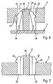
- FIG. 5 shows a sectional view of the fastener along line V-V in FIG. 2 .
- FIG. 6 shows a view corresponding to FIG. 5 , but during the passage of the fastener through an opening of the retention plate.
- FIG. 7 shows a view corresponding to FIG. 5 , but after the passage of the fastener through the opening of the retention plate.
- Plastic housing 2 shown in FIG. 1 is used for receiving an acceleration sensor (not shown) of a motor vehicle, which is inserted through an upper installation opening 4 into housing 2 .
- housing 2 having the acceleration sensor is mounted in a predefined orientation in relation to the motor vehicle on a retention plate 6 , which forms a part of a body of the motor vehicle and is provided with two punched-out passage openings 8 , 10 , of which opening 8 has a circular opening cross section and opening 10 has a noncircular opening cross section.
- housing 2 For mounting on retention plate 6 , housing 2 has a fastener 14 projecting beyond a wide lateral face 12 , which is clipped into opening 10 of retention plate 6 , as well as a cylindrical steel sleeve 16 , molded into housing 2 during the manufacturing of housing 2 by injection molding of a plastic reinforced with 30% glass fibers and thus integrally connected to housing 2 , which is flush with opening 8 of retention plate 6 after fastener 14 is clipped into opening 10 , so that a self-tapping fastening screw (not shown) having a cylindrical shaft part may be screwed using one hand through steel sleeve 16 into opening 8 , i.e., without housing 2 of the acceleration sensor, which is fixed in relation to retention plate 6 using fastener 14 , having to be held in place using the other hand.
- a self-tapping fastening screw (not shown) having a cylindrical shaft part may be screwed using one hand through steel sleeve 16 into opening 8 , i.e., without housing 2
- the center-to-center distance of both openings 8 , 10 corresponds to the distance between a central axis of steel sleeve 16 and a central axis of fastener 14 parallel thereto.
- fastener 14 has an outline adapted to the opening cross section of opening 10 , so that it may only be inserted into opening 10 in a predetermined orientation, in which steel sleeve 16 comes to rest precisely in front of opening 8 of retention plate 6 .
- opening 10 is formed by a short oblong hole, in which two semicylindrical limiting wall sections 18 are connected by two diametrically opposing short flat limiting wall sections 20 .
- Fastener 14 has an outline complementary thereto, as shown best in FIG. 4 , this outline comprising two opposing partial cylindrical peripheral surface sections 22 , which are congruent to limiting wall sections 18 of opening 10 , but extend over an arc angle that is slightly less than 180°.
- two fasteners (not shown) used for clipping into the openings of the retention plate may be provided at a distance from one another and from steel sleeve 16 on housing 2 of the acceleration sensor, in which case the two fasteners and the associated openings may also be provided with a circular outline and/or opening cross section.
- Fastener 14 shown in the drawing essentially includes a projection 24 which is molded onto housing 2 and projects beyond wide lateral face 12 , and two elastically flexible catch pins 28 , which are situated at a distance from one another in lateral recesses 26 of projection 24 and also are molded onto housing 2 while projecting beyond it.
- catch pins 28 are used for clipping into opening 10 and thus for latching housing 2 on retention plate 6
- projection 24 is firstly used as a protection for catch pins 28 before mounting, which are housed well protected from shocks and impacts in recesses 26 of projection 24 , secondly as a positioning aid during the mounting of housing 2 , in that it positions steel sleeve 16 , as described above, precisely in front of opening 8 of retention plate 6 , and thirdly as an antirotation device, in that it prevents housing 2 from twisting in relation to retention plate 6 if a torque is applied to housing 2 in relation to retention plate 6 as the fastening screw is screwed in.
- Each catch pin 28 has a shaft part 30 having a square or rectangular cross section and a free end implemented as a catch hook, which is formed by a catch lug 32 projecting beyond the exterior side of shaft part 30 of each catch pin 28 .
- catch lugs 32 of both catch pins 28 engage behind its edge facing away from housing 2 in the area of both limiting wall sections 20 in FIG. 1 .
- catch lugs 32 are provided in a known way with insertion bevels 34 .
- the catch lugs are slightly beveled at 35 on their rear side facing housing 2 .
- projection 24 includes two parts 36 which are situated at a distance from one another on both sides of catch pins 28 , have a cross section in the shape of a circular segment, and are connected to one another in one piece by a web 38 having a rectangular cross section situated in the middle between catch pins 28 .
- Both parts 36 and web 38 together delimit both recesses 26 , which are open toward opposite sides, extend over the entire length of projection 24 , and have a rectangular cross section, whose cross-sectional dimensions are greater than the cross-sectional dimensions of catch pins 28 .
- projection 24 is provided in the area of parts 36 with partial cylindrical peripheral surface sections 22 , whose central axes M lie at a distance from one another, corresponding to the width of limiting wall parts (sections) 20 of opening 10 , in two parallel planes E spanned by adjacent flat lateral faces 40 , 42 of both catch pins 28 , so that flat exterior sides 44 of shaft parts 30 of catch pins 28 come to rest flatly against their limiting wall sections 20 after fastener 14 is inserted into opening 10 , when catch lugs 32 engage behind the edge of opening 10 facing away from housing 2 and/or the wide lateral face of retention plate 6 facing away from housing 2 .
- fastener 14 is mirror symmetric to a plane running through central axes M of peripheral surface sections 22 as well as a plane perpendicular thereto in the center between both central axes M.
- projection 24 has a tapered free end which is formed by two rounded front ends 50 of both parts 36 in the shape of spherical segments and a flat front end 52 of web 38 .
Abstract
Description
Claims (17)
Applications Claiming Priority (4)
| Application Number | Priority Date | Filing Date | Title |
|---|---|---|---|
| DE102006027751A DE102006027751A1 (en) | 2006-06-16 | 2006-06-16 | Fastening element for fastening and / or prefixing of a component to a holder provided with an opening and component with fastening element |
| DE102006027751.1 | 2006-06-16 | ||
| DE102006027751 | 2006-06-16 | ||
| PCT/EP2007/055226 WO2007144260A1 (en) | 2006-06-16 | 2007-05-30 | Fastening element for fastening and/or temporarily fastening a component to a mount which is provided with an opening, and a component with a fastening element |
Publications (2)
| Publication Number | Publication Date |
|---|---|
| US20090300893A1 US20090300893A1 (en) | 2009-12-10 |
| US9233653B2 true US9233653B2 (en) | 2016-01-12 |
Family
ID=38349533
Family Applications (1)
| Application Number | Title | Priority Date | Filing Date |
|---|---|---|---|
| US12/227,507 Active 2029-08-24 US9233653B2 (en) | 2006-06-16 | 2007-05-30 | Fastener for fastening and/or temporarily fixing a component on a retainer provided with an opening, as well as a component having a fastener |
Country Status (6)
| Country | Link |
|---|---|
| US (1) | US9233653B2 (en) |
| EP (1) | EP2035260B1 (en) |
| JP (1) | JP5080572B2 (en) |
| DE (1) | DE102006027751A1 (en) |
| ES (1) | ES2386985T3 (en) |
| WO (1) | WO2007144260A1 (en) |
Families Citing this family (15)
| Publication number | Priority date | Publication date | Assignee | Title |
|---|---|---|---|---|
| DE102008011676A1 (en) * | 2008-02-28 | 2009-09-03 | Robert Bosch Gmbh | Sensor housing with fastening means |
| DE102009045722B4 (en) | 2009-10-15 | 2021-09-16 | Robert Bosch Gmbh | Component carrier |
| DE102010030806A1 (en) * | 2010-07-01 | 2012-01-05 | Continental Teves Ag & Co. Ohg | fastening device |
| US8382060B2 (en) | 2010-09-14 | 2013-02-26 | Bendix Commercial Vehicle Systems Llc | Component orientation element |
| DE102012202982A1 (en) | 2012-02-28 | 2013-08-29 | Robert Bosch Gmbh | Fastening element for fastening and pre-fixing of component to holder in component arrangement of motor vehicle, has projection which is provided with recess that extends over axial length of projection |
| JP6307498B2 (en) * | 2012-06-05 | 2018-04-04 | イリノイ トゥール ワークス インコーポレイティド | Adjustable mating fastener assembly |
| US8723035B2 (en) * | 2012-08-31 | 2014-05-13 | Flextronics Ap, Llc | Vibration reduction rib |
| DE202013010542U1 (en) * | 2013-11-25 | 2014-01-20 | Lisa Dräxlmaier GmbH | Housing with plastic insert |
| US9260071B2 (en) * | 2014-03-11 | 2016-02-16 | Trw Automotive U.S. Llc | Apparatus for snap mounting a crash sensor |
| JP6321423B2 (en) * | 2014-03-26 | 2018-05-09 | 住友理工株式会社 | Piping fixture |
| US9470595B2 (en) | 2014-08-29 | 2016-10-18 | Trw Automotive U.S. Llc | Apparatus for dry side mounting a crash pressure sensor |
| DE102014218756A1 (en) * | 2014-09-18 | 2016-03-24 | Continental Teves Ag & Co. Ohg | Form-fitting on the vehicle attachable level sensor |
| DE102014223404A1 (en) * | 2014-11-17 | 2016-05-19 | Robert Bosch Gmbh | Fixing device for an electronic component, in particular an acceleration sensor for airbag systems |
| US10883863B2 (en) * | 2017-11-21 | 2021-01-05 | Veoneer Us, Inc. | Interchangeable sensor mounting |
| WO2021096623A1 (en) * | 2019-11-11 | 2021-05-20 | Cummins Inc. | Modular engine shipping skid |
Citations (30)
| Publication number | Priority date | Publication date | Assignee | Title |
|---|---|---|---|---|
| US715891A (en) * | 1902-02-28 | 1902-12-16 | William A Somerby | Nut-lock. |
| GB213716A (en) | 1923-01-27 | 1924-04-10 | Carl Robert Hugo Bonn | Improvements in and relating to flow meters |
| US3803670A (en) * | 1971-04-21 | 1974-04-16 | W Johnson | Fastener device |
| EP0116013A2 (en) | 1983-01-31 | 1984-08-15 | Paul Zöllig AG | Device for variable compartments for drawers |
| US4782562A (en) * | 1987-05-21 | 1988-11-08 | Emhart Enterprises Corp. | Two-part plastic clip |
| US4865505A (en) * | 1987-02-28 | 1989-09-12 | Kato Hatsujo Kaisha, Ltd. | Structure for mounting automobile interior upholstering material |
| US5145076A (en) * | 1990-11-13 | 1992-09-08 | Zeftek, Inc. | Plastic knuckle pin with annular relief grooves for preventing pin failure due to fatigue |
| JPH0544713A (en) | 1991-08-08 | 1993-02-23 | Nippondenso Co Ltd | Lock construction for link plate |
| US5228816A (en) * | 1991-08-07 | 1993-07-20 | A. Raymond & Cie. | Plastic clip |
| US5326082A (en) * | 1992-06-10 | 1994-07-05 | Bridgestone/Firestone, Inc. | Self locking, snap mounted attachment device |
| US5384940A (en) * | 1992-02-28 | 1995-01-31 | Aavid Engineering, Inc. | Self-locking heat sinks for surface mount devices |
| DE29519083U1 (en) | 1995-12-01 | 1996-01-25 | Audi Ag | Positioning pin set |
| DE19517676A1 (en) | 1995-05-13 | 1996-11-14 | Bosch Gmbh Robert | Pressure sensor for internal combustion engine with induction manifold pipe |
| US5592720A (en) * | 1994-12-06 | 1997-01-14 | Yazaki Corporation | Mounting clip |
| JPH0932822A (en) | 1995-07-19 | 1997-02-04 | Yazaki Corp | Fastening structure |
| US5945606A (en) | 1996-08-30 | 1999-08-31 | Desno Corporation | Elastic member, and method and structure for attaching sensor to sensor attachment member using the same |
| US6474921B1 (en) * | 2001-07-17 | 2002-11-05 | Trw Inc. | Two part twist fastener |
| US20030016916A1 (en) * | 2001-07-13 | 2003-01-23 | Allen Mark D | Modular multi-fiber/conductor connector and insert |
| EP1291534A1 (en) | 2001-09-07 | 2003-03-12 | ITW Sverige AB | Releasable clip |
| EP1387091A1 (en) | 2002-08-02 | 2004-02-04 | Robert Bosch Gmbh | Fastening device |
| US20040244158A1 (en) * | 2003-06-06 | 2004-12-09 | Mitsubishi Denki Kabushiki Kaisha | Snap fit mechanism |
| USD500245S1 (en) * | 2003-11-21 | 2004-12-28 | Piolax, Inc. | Article for fixing panel |
| US20050244250A1 (en) | 2004-04-30 | 2005-11-03 | Piolax Inc. | Clip |
| DE102005018833A1 (en) | 2004-06-21 | 2006-01-19 | Daimlerchrysler Ag | Device for attaching cladding part to unfinished part of motor vehicle has mounting element attached to unfinished component that protrudes towards inner side of cladding element and is passed through by transverse element |
| US7019215B2 (en) | 2001-07-05 | 2006-03-28 | Yazaki Corporation | Wiring harness clamp |
| EP1647424A1 (en) | 2004-09-15 | 2006-04-19 | The Goodyear Tire & Rubber Company | Air spring mount with snap-in-place attachment |
| DE102004035805A1 (en) | 2004-07-23 | 2006-04-20 | Siemens Ag | Electrical device e.g. sensor, housing for motor vehicle, has position pin with snap-fit, and fastener that is fixed detachably at or in passage so that fastener protrudes with section over lower surface of housing |
| US7036779B2 (en) | 2003-07-24 | 2006-05-02 | Sumitomo Wiring Systems, Ltd. | Locking structure for a clamp |
| USD566534S1 (en) * | 2006-02-17 | 2008-04-15 | Piolax, Inc. | Fixing article for automobile parts |
| US20110272547A1 (en) * | 2010-05-06 | 2011-11-10 | Yazaki Corporation | Wiring harness fixture |
Family Cites Families (6)
| Publication number | Priority date | Publication date | Assignee | Title |
|---|---|---|---|---|
| JPS5750892U (en) * | 1980-09-05 | 1982-03-24 | ||
| GB2137816A (en) * | 1983-04-05 | 1984-10-10 | Alan Hilton Shaw | Holding devices |
| JPH0242892Y2 (en) * | 1985-06-21 | 1990-11-15 | ||
| JPH0326332Y2 (en) * | 1985-12-11 | 1991-06-07 | ||
| JP3942340B2 (en) * | 2000-06-20 | 2007-07-11 | 第一電子工業株式会社 | securing bracket |
| NL1027731C2 (en) * | 2004-12-13 | 2006-06-14 | Zandbergen Ind Plaatwerk | Fixing element for fixing panels to each other as well as a cabinet with panels connected by such a fixing element. |
-
2006
- 2006-06-16 DE DE102006027751A patent/DE102006027751A1/en not_active Ceased
-
2007
- 2007-05-30 US US12/227,507 patent/US9233653B2/en active Active
- 2007-05-30 ES ES07729643T patent/ES2386985T3/en active Active
- 2007-05-30 WO PCT/EP2007/055226 patent/WO2007144260A1/en active Application Filing
- 2007-05-30 EP EP07729643A patent/EP2035260B1/en active Active
- 2007-05-30 JP JP2009514734A patent/JP5080572B2/en active Active
Patent Citations (30)
| Publication number | Priority date | Publication date | Assignee | Title |
|---|---|---|---|---|
| US715891A (en) * | 1902-02-28 | 1902-12-16 | William A Somerby | Nut-lock. |
| GB213716A (en) | 1923-01-27 | 1924-04-10 | Carl Robert Hugo Bonn | Improvements in and relating to flow meters |
| US3803670A (en) * | 1971-04-21 | 1974-04-16 | W Johnson | Fastener device |
| EP0116013A2 (en) | 1983-01-31 | 1984-08-15 | Paul Zöllig AG | Device for variable compartments for drawers |
| US4865505A (en) * | 1987-02-28 | 1989-09-12 | Kato Hatsujo Kaisha, Ltd. | Structure for mounting automobile interior upholstering material |
| US4782562A (en) * | 1987-05-21 | 1988-11-08 | Emhart Enterprises Corp. | Two-part plastic clip |
| US5145076A (en) * | 1990-11-13 | 1992-09-08 | Zeftek, Inc. | Plastic knuckle pin with annular relief grooves for preventing pin failure due to fatigue |
| US5228816A (en) * | 1991-08-07 | 1993-07-20 | A. Raymond & Cie. | Plastic clip |
| JPH0544713A (en) | 1991-08-08 | 1993-02-23 | Nippondenso Co Ltd | Lock construction for link plate |
| US5384940A (en) * | 1992-02-28 | 1995-01-31 | Aavid Engineering, Inc. | Self-locking heat sinks for surface mount devices |
| US5326082A (en) * | 1992-06-10 | 1994-07-05 | Bridgestone/Firestone, Inc. | Self locking, snap mounted attachment device |
| US5592720A (en) * | 1994-12-06 | 1997-01-14 | Yazaki Corporation | Mounting clip |
| DE19517676A1 (en) | 1995-05-13 | 1996-11-14 | Bosch Gmbh Robert | Pressure sensor for internal combustion engine with induction manifold pipe |
| JPH0932822A (en) | 1995-07-19 | 1997-02-04 | Yazaki Corp | Fastening structure |
| DE29519083U1 (en) | 1995-12-01 | 1996-01-25 | Audi Ag | Positioning pin set |
| US5945606A (en) | 1996-08-30 | 1999-08-31 | Desno Corporation | Elastic member, and method and structure for attaching sensor to sensor attachment member using the same |
| US7019215B2 (en) | 2001-07-05 | 2006-03-28 | Yazaki Corporation | Wiring harness clamp |
| US20030016916A1 (en) * | 2001-07-13 | 2003-01-23 | Allen Mark D | Modular multi-fiber/conductor connector and insert |
| US6474921B1 (en) * | 2001-07-17 | 2002-11-05 | Trw Inc. | Two part twist fastener |
| EP1291534A1 (en) | 2001-09-07 | 2003-03-12 | ITW Sverige AB | Releasable clip |
| EP1387091A1 (en) | 2002-08-02 | 2004-02-04 | Robert Bosch Gmbh | Fastening device |
| US20040244158A1 (en) * | 2003-06-06 | 2004-12-09 | Mitsubishi Denki Kabushiki Kaisha | Snap fit mechanism |
| US7036779B2 (en) | 2003-07-24 | 2006-05-02 | Sumitomo Wiring Systems, Ltd. | Locking structure for a clamp |
| USD500245S1 (en) * | 2003-11-21 | 2004-12-28 | Piolax, Inc. | Article for fixing panel |
| US20050244250A1 (en) | 2004-04-30 | 2005-11-03 | Piolax Inc. | Clip |
| DE102005018833A1 (en) | 2004-06-21 | 2006-01-19 | Daimlerchrysler Ag | Device for attaching cladding part to unfinished part of motor vehicle has mounting element attached to unfinished component that protrudes towards inner side of cladding element and is passed through by transverse element |
| DE102004035805A1 (en) | 2004-07-23 | 2006-04-20 | Siemens Ag | Electrical device e.g. sensor, housing for motor vehicle, has position pin with snap-fit, and fastener that is fixed detachably at or in passage so that fastener protrudes with section over lower surface of housing |
| EP1647424A1 (en) | 2004-09-15 | 2006-04-19 | The Goodyear Tire & Rubber Company | Air spring mount with snap-in-place attachment |
| USD566534S1 (en) * | 2006-02-17 | 2008-04-15 | Piolax, Inc. | Fixing article for automobile parts |
| US20110272547A1 (en) * | 2010-05-06 | 2011-11-10 | Yazaki Corporation | Wiring harness fixture |
Non-Patent Citations (1)
| Title |
|---|
| Atsuhiko Yamanaka, Toshihiro Kashima, and Kenji Hosoyama Coil Bobbin Composed of High-Strength Polyethylene Fiber Reinforced Plastics for a Stable High-Field Superconducting Magnet IEEE Transactions on Applied Superconductivity, vol. 11, No. 3, Sep. 2001. * |
Also Published As
| Publication number | Publication date |
|---|---|
| JP5080572B2 (en) | 2012-11-21 |
| DE102006027751A1 (en) | 2007-12-20 |
| JP2009540239A (en) | 2009-11-19 |
| EP2035260B1 (en) | 2012-07-11 |
| WO2007144260A1 (en) | 2007-12-21 |
| ES2386985T3 (en) | 2012-09-10 |
| US20090300893A1 (en) | 2009-12-10 |
| EP2035260A1 (en) | 2009-03-18 |
Similar Documents
| Publication | Publication Date | Title |
|---|---|---|
| US9233653B2 (en) | Fastener for fastening and/or temporarily fixing a component on a retainer provided with an opening, as well as a component having a fastener | |
| CA2296991C (en) | Fastener provided with a snapping-in foot to be pushed in through a hole in a panel | |
| US20090089982A1 (en) | Trim retainer | |
| US20050016116A1 (en) | One-piece integrated snap fastening mechanism | |
| EP1882612A2 (en) | Interior Trim Fastener System | |
| US10001502B2 (en) | Fastening device for an electronic component, in particular an acceleration sensor for airbag systems | |
| EP2416020A1 (en) | Clip | |
| EP1849643A3 (en) | Fuel flap for automobiles | |
| BR9807041A (en) | Fastening element | |
| US20060168896A1 (en) | Cursor assembly for a window regulator, in particular for vehicles | |
| US20090007511A1 (en) | Window Unit Having Decorative Strip Mounted Thereon | |
| KR101081763B1 (en) | Windshield wiper, especially for a motor vehicle | |
| US20180252250A1 (en) | Toggle fixing | |
| WO2008070700A1 (en) | Fastener | |
| JP2003514196A (en) | Mounting bracket for removably fixing to furniture | |
| US2695435A (en) | Trim fastening device | |
| CN107776520B (en) | Motor vehicle and fastening device for a motor vehicle | |
| US20090238659A1 (en) | Fastening Device Having Fastening Element | |
| US7325852B1 (en) | Cluster mounting bracket | |
| US20080109988A1 (en) | Door stop retainer assembly | |
| EP2318722B1 (en) | Fastening device and method for fastening an element in a key-hole shaped cut-out of a wall | |
| DE102007060625A1 (en) | Ultrasonic sensor mounting, at a motor vehicle fender, has a moving shield within limits for protection against flying stones/chips | |
| US20120001446A1 (en) | Trim component comprising fastening means | |
| US9321409B2 (en) | Installation frame for accommodating a device in an installation opening | |
| US20190242419A1 (en) | System for fastening a planar element to a component and fastening clip for use in such a system |
Legal Events
| Date | Code | Title | Description |
|---|---|---|---|
| AS | Assignment |
Owner name: ROBERT BOSCH GMBH, GERMANY Free format text: ASSIGNMENT OF ASSIGNORS INTEREST;ASSIGNORS:HERRMANN, ALEXANDER;FERNANDEZ, ANTONIO BRUNA;WOERNLE, WOLFGANG;AND OTHERS;SIGNING DATES FROM 20081009 TO 20090512;REEL/FRAME:023063/0063 Owner name: ROBERT BOSCH GMBH, GERMANY Free format text: ASSIGNMENT OF ASSIGNORS INTEREST;ASSIGNORS:HERRMANN, ALEXANDER;FERNANDEZ, ANTONIO BRUNA;WOERNLE, WOLFGANG;AND OTHERS;REEL/FRAME:023063/0063;SIGNING DATES FROM 20081009 TO 20090512 |
|
| STCF | Information on status: patent grant |
Free format text: PATENTED CASE |
|
| MAFP | Maintenance fee payment |
Free format text: PAYMENT OF MAINTENANCE FEE, 4TH YEAR, LARGE ENTITY (ORIGINAL EVENT CODE: M1551); ENTITY STATUS OF PATENT OWNER: LARGE ENTITY Year of fee payment: 4 |
|
| MAFP | Maintenance fee payment |
Free format text: PAYMENT OF MAINTENANCE FEE, 8TH YEAR, LARGE ENTITY (ORIGINAL EVENT CODE: M1552); ENTITY STATUS OF PATENT OWNER: LARGE ENTITY Year of fee payment: 8 |