US9245399B2 - Media authentication - Google Patents
Media authentication Download PDFInfo
- Publication number
- US9245399B2 US9245399B2 US13/919,064 US201313919064A US9245399B2 US 9245399 B2 US9245399 B2 US 9245399B2 US 201313919064 A US201313919064 A US 201313919064A US 9245399 B2 US9245399 B2 US 9245399B2
- Authority
- US
- United States
- Prior art keywords
- signal
- magnetic
- media item
- test
- features
- Prior art date
- Legal status (The legal status is an assumption and is not a legal conclusion. Google has not performed a legal analysis and makes no representation as to the accuracy of the status listed.)
- Active, expires
Links
- 238000000034 method Methods 0.000 claims abstract description 86
- 238000012360 testing method Methods 0.000 claims description 105
- 230000004044 response Effects 0.000 claims description 12
- 238000012935 Averaging Methods 0.000 claims description 9
- 238000012545 processing Methods 0.000 claims description 6
- 239000000976 ink Substances 0.000 claims 4
- 238000012549 training Methods 0.000 description 64
- 230000008569 process Effects 0.000 description 27
- 238000005070 sampling Methods 0.000 description 12
- 230000032258 transport Effects 0.000 description 10
- 238000000605 extraction Methods 0.000 description 9
- 238000001514 detection method Methods 0.000 description 7
- 238000001914 filtration Methods 0.000 description 7
- 230000006870 function Effects 0.000 description 7
- 238000011524 similarity measure Methods 0.000 description 7
- 230000003044 adaptive effect Effects 0.000 description 5
- 230000003287 optical effect Effects 0.000 description 5
- 238000007781 pre-processing Methods 0.000 description 5
- 230000008901 benefit Effects 0.000 description 4
- 238000003384 imaging method Methods 0.000 description 4
- 238000004422 calculation algorithm Methods 0.000 description 3
- 238000004590 computer program Methods 0.000 description 3
- 230000000694 effects Effects 0.000 description 3
- 238000010183 spectrum analysis Methods 0.000 description 3
- 230000007723 transport mechanism Effects 0.000 description 3
- 238000010200 validation analysis Methods 0.000 description 3
- 230000001174 ascending effect Effects 0.000 description 2
- 238000004364 calculation method Methods 0.000 description 2
- 238000010586 diagram Methods 0.000 description 2
- 238000005286 illumination Methods 0.000 description 2
- KJLLKLRVCJAFRY-UHFFFAOYSA-N mebutizide Chemical compound ClC1=C(S(N)(=O)=O)C=C2S(=O)(=O)NC(C(C)C(C)CC)NC2=C1 KJLLKLRVCJAFRY-UHFFFAOYSA-N 0.000 description 2
- 238000003909 pattern recognition Methods 0.000 description 2
- 230000009467 reduction Effects 0.000 description 2
- 230000003595 spectral effect Effects 0.000 description 2
- 239000000654 additive Substances 0.000 description 1
- 230000000996 additive effect Effects 0.000 description 1
- 230000009286 beneficial effect Effects 0.000 description 1
- 239000002131 composite material Substances 0.000 description 1
- 238000013461 design Methods 0.000 description 1
- 238000007689 inspection Methods 0.000 description 1
- 238000003064 k means clustering Methods 0.000 description 1
- 239000011159 matrix material Substances 0.000 description 1
- 238000005259 measurement Methods 0.000 description 1
- 238000012986 modification Methods 0.000 description 1
- 230000004048 modification Effects 0.000 description 1
- 230000001902 propagating effect Effects 0.000 description 1
- 238000007619 statistical method Methods 0.000 description 1
- 238000012546 transfer Methods 0.000 description 1
- 230000002087 whitening effect Effects 0.000 description 1
Images


Classifications
-
- G—PHYSICS
- G07—CHECKING-DEVICES
- G07D—HANDLING OF COINS OR VALUABLE PAPERS, e.g. TESTING, SORTING BY DENOMINATIONS, COUNTING, DISPENSING, CHANGING OR DEPOSITING
- G07D7/00—Testing specially adapted to determine the identity or genuineness of valuable papers or for segregating those which are unacceptable, e.g. banknotes that are alien to a currency
- G07D7/04—Testing magnetic properties of the materials thereof, e.g. by detection of magnetic imprint
-
- G06K9/186—
-
- G—PHYSICS
- G06—COMPUTING; CALCULATING OR COUNTING
- G06V—IMAGE OR VIDEO RECOGNITION OR UNDERSTANDING
- G06V30/00—Character recognition; Recognising digital ink; Document-oriented image-based pattern recognition
- G06V30/10—Character recognition
- G06V30/22—Character recognition characterised by the type of writing
- G06V30/224—Character recognition characterised by the type of writing of printed characters having additional code marks or containing code marks
- G06V30/2253—Recognition of characters printed with magnetic ink
-
- G—PHYSICS
- G07—CHECKING-DEVICES
- G07D—HANDLING OF COINS OR VALUABLE PAPERS, e.g. TESTING, SORTING BY DENOMINATIONS, COUNTING, DISPENSING, CHANGING OR DEPOSITING
- G07D7/00—Testing specially adapted to determine the identity or genuineness of valuable papers or for segregating those which are unacceptable, e.g. banknotes that are alien to a currency
- G07D7/06—Testing specially adapted to determine the identity or genuineness of valuable papers or for segregating those which are unacceptable, e.g. banknotes that are alien to a currency using wave or particle radiation
- G07D7/12—Visible light, infrared or ultraviolet radiation
-
- G—PHYSICS
- G07—CHECKING-DEVICES
- G07D—HANDLING OF COINS OR VALUABLE PAPERS, e.g. TESTING, SORTING BY DENOMINATIONS, COUNTING, DISPENSING, CHANGING OR DEPOSITING
- G07D7/00—Testing specially adapted to determine the identity or genuineness of valuable papers or for segregating those which are unacceptable, e.g. banknotes that are alien to a currency
- G07D7/16—Testing the dimensions
- G07D7/162—Length or width
-
- G—PHYSICS
- G07—CHECKING-DEVICES
- G07D—HANDLING OF COINS OR VALUABLE PAPERS, e.g. TESTING, SORTING BY DENOMINATIONS, COUNTING, DISPENSING, CHANGING OR DEPOSITING
- G07D7/00—Testing specially adapted to determine the identity or genuineness of valuable papers or for segregating those which are unacceptable, e.g. banknotes that are alien to a currency
- G07D7/20—Testing patterns thereon
- G07D7/202—Testing patterns thereon using pattern matching
-
- G—PHYSICS
- G07—CHECKING-DEVICES
- G07D—HANDLING OF COINS OR VALUABLE PAPERS, e.g. TESTING, SORTING BY DENOMINATIONS, COUNTING, DISPENSING, CHANGING OR DEPOSITING
- G07D7/00—Testing specially adapted to determine the identity or genuineness of valuable papers or for segregating those which are unacceptable, e.g. banknotes that are alien to a currency
Definitions
- the present invention relates to media authentication, such as automated banknote authentication.
- genuine banknotes include a variety of security features. Some of these security features can be detected using imaging sensors, such as a fluorescent security feature (which responds to an ultra-violet light source), an infra-red security feature (which produces a characteristic response to an infra-red light source), and the like. However, some types of security feature cannot be detected using an imaging sensor.
- One such security feature is magnetic ink, which is used to print some parts of a banknote.
- the invention generally provides methods, systems, apparatus, and software for authenticating a media item by comparing features extracted from a processed magnetic signal to features extracted from a reference template created only from genuine media items.
- a method of authenticating a media item comprising: measuring a magnetic signal along the media item, converting the measured signal to a calibrated length signal, aligning the calibrated length signal with a reference signal, extracting features from the aligned signal, and classifying the media item based on the extracted features.
- the step of measuring a magnetic signal along the media item may comprise measuring a plurality of magnetic signals along the media item.
- the plurality of magnetic signals may be provided by a plurality of magnetic read heads extending over the width (for example, where the media item is transported short edge first) or length (for example, where the media item is transported short edge first) of the media item as it is transported passed the magnetic read heads.
- the output of each magnetic read head may be referred to as a channel.
- Each channel may provide a continuous output signal that is sampled to produce individual data points.
- a suitable sampling rate may be several thousands of readings per second (for example, 5800 readings per second).
- the media item may be transported at several hundreds of millimeters per second, for example, approximately 700 mm per second.
- the method may include the additional step, after measuring the signal, of removing system noise from the measured signal.
- the step of removing system noise from the measured signal may be implemented by performing Fourier analysis to ascertain the desired frequency range, applying a Fast Fourier Transform (FFT), setting the discrete FFT coefficients to zero outside the desired frequency range, and then applying an Inverse Fast Fourier Transform to remove the frequencies corresponding to system noise.
- FFT Fast Fourier Transform
- the method may include the additional step, for example, after measuring the signal or after removing system noise from the measured signal, of averaging every ⁇ sampled points (from each channel) to create one averaged sample point. This reduces the number of points to be processed by ⁇ , where ⁇ is a value chosen to give the desired reduction. There may not be much advantage in implementing this step in a very high speed processing system, although it may still be performed to average out noise from the measured signals.
- the length of the measured signal from one media item may differ from the length of the measured signal from another example of the same media type.
- two banknotes of the same currency, denomination, and series may have slightly different magnetic signal lengths. It is even possible that different channels measuring the same media item may produce a different signal length. This is why the method may include the step of converting the measured signal to a calibrated length signal.
- Converting the measured signal to a calibrated length signal may comprise ascertaining a center point of the measured signal length and cropping the measured signal length to half of the desired length in opposite directions from the center point.
- converting the measured signal to a calibrated length signal may comprise ascertaining leading edge coordinates of the media item from other sensors (for example, an imaging sensor), and cropping the measured signal length using the desired length and the actual media item starting point.
- sensors for example, an imaging sensor
- the desired length may be slightly shorter than the standard media item length (for example, by a constant value c) to accommodate shrinkage of the media item.
- the method may include the further step (preferably after the step of converting the measured signal to a calibrated length signal) of normalizing the magnetic signal.
- the step of normalizing the magnetic signal may comprise the steps of calculating the mean value of the magnetic signal and subtracting the mean value of the magnetic signal from the magnetic signal. This may be applied to the calibrated length signal, the averaged signal, or the measured signal. By subtracting the mean value of the signal from the signal, a calibrated amplitude signal is provided.
- normalizing the magnetic signal may be implemented by any other convenient technique such as dividing the signal by its maximum value, or using a standard whitening process.
- the step of aligning the calibrated length signal with a reference signal may comprise the steps of: (i) retrieving a reference signal corresponding to the calibrated length signal from a template (for example, from a corresponding channel in the template), and (ii) minimizing the root mean square (RMS) errors between the calibrated length signal and the reference signal.
- a template for example, from a corresponding channel in the template
- RMS root mean square
- the reference signal may be any signal selected from a training set (for example, for a corresponding channel), or the average (or some other combination) of all signals of the training set (for the corresponding channel).
- Minimizing the RMS errors may be implemented by shifting the calibrated length signal along the sampling position axis. For each shift (that is, for each shift by one sampling position), the RMS value between the shifted signal and the reference signal is calculated. After evaluating all possible shifts within a defined the range (for example, from minus ten sampling positions to plus ten sampling positions), the shift with the minimal RMS value is selected; and the corresponding shifted signal is regarded as the aligned signal.
- MSE mean square error
- Euclidean distance technique Euclidean distance technique
- cosine distance technique any other convenient similarity, error or distance metric technique.
- Aligning the calibrated length signal with a reference reduces the effects of vibration and friction in the transport system (the system that transports the media item), and also reduces the effects of rotation, skew, shrinkage, and the like of the media item.
- the aligned signals may still consist of some small noise, particularly in the sections where there is no magnetic feature, so further noise reduction and filtering may be required.
- a threshold ⁇ may be introduced so that any value within the range of [ ⁇ , ⁇ ] will be set to 0.
- the step of extracting features from the aligned signal may comprise the steps of (i) extracting features from the spatial domain, and/or (ii) extracting features from the frequency domain.
- the optional step of extracting features from the spatial domain may be implemented using any convenient model that is capable of inferring a degree of match between two one-dimensional signals in the spatial domain.
- One type of model is a Pearson Product-Moment Correlation Coefficient (PPMCC) model, described, for example, in J. L. Rodgers and W. A. Nicewander, Thirteen ways to look at the correlation coefficient, The American Statistician, 42(1): 59-66, February 1988.
- PMCC Pearson Product-Moment Correlation Coefficient
- Other convenient models include (i) the Intersection Score adapted from the color histogram intersection matching in M. J. Swain and D. H. Ballard, Color Indexing, International Journal of Computer Vision, 7(1): 11-32, 1991; (ii) the Hamming distance described in R. W.
- the selected spatial domain model for example, PPMCC
- features are extracted that indicate the degree of match between the aligned signal and the corresponding reference.
- the corresponding reference may comprise a composite signal, or a plurality of signals, from a training set.
- the corresponding reference relates to the same channel as the aligned signal.
- the type of spatial features (that is, the spatial domain model) is also specified by the template.
- the optional step of extracting features from the frequency domain may be implemented using a Discrete Fourier Transform (DFT), which transforms a signal from the time domain into the frequency domain, producing coefficients corresponding to different frequency components.
- DFT Discrete Fourier Transform
- the DFT can be implemented using the Fast Fourier Transform (FFT) algorithm.
- the optional step of extracting features from the frequency domain may further include removing high frequency components (since these usually only relate to noise) and using the predefined first n (where n is a whole number) frequency components for feature extraction.
- the frequency features can be extracted from the sum of signals from all selected channels.
- pre-processing of the magnetic signal is not necessary.
- the step of classifying the media item based on the extracted features may comprise a positive test and/or a negative test.
- the positive test may comprise validating that the aligned signal from the media item has an expected magnetic response at the spatial locations corresponding to the magnetic ink printed areas of a genuine media item (the reference).
- the negative test may comprise validating that the aligned signal from the media item has no magnetic response at the spatial locations that are not magnetic-ink-printed in a genuine media item (the reference).
- the positive test may comprise (i) implementing a threshold test for spatial features extracted from the aligned signal and/or (ii) implementing a D 2 test for frequency features extracted from the aligned signal.
- the threshold test may be implemented by calculating the average of the spatial feature values (there would be one spatial feature value for each channel, and these would be averaged to produce a single average feature value) and comparing the average feature value to a threshold derived from a training set. The media item would pass the test if its average feature value is greater than or equal to the threshold, otherwise it would fail the test.
- the threshold test may be implemented by comparing the spatial feature value of each selected channel to the corresponding threshold for that channel (derived from the training set). The results for each of the individual channels can then be combined together to provide the final decision. Any decision combination technique may be used. One example is to use majority voting, where the media item passes the test if the majority of the channels have a feature value greater than or equal to the threshold; otherwise it would fail the test.
- the negative test may comprise (i) ascertaining start and end coordinates of each area of the media item that should not have a magnetic response (each a magnetic-free zone) by accessing data stored in a reference, (ii) calculating, for each magnetic-free zone, a ratio of non-zero points to all points along the length of the magnetic-free zone (for example, if there are 100 points and 45 of these points are non-zero points, then the ratio is 0.45), and (iii) calculating an overall average of the ratios for all magnetic-free zones (in all channels, if multiple channels are used) (the overall false ratio). If the overall false ratio is less than or equal to a threshold specified by a reference, the media item passes the test; otherwise the media item fails the test.
- the step of classifying the media item based on the extracted features may further comprise combining the results of the positive test and the negative test.
- the results may be combined by using a unanimous vote so that a media item is only passed as genuine if the media item passes both the positive test and the negative test.
- the results may be combined by using weighting factors to reflect the characteristics of individual media items.
- the combined results may be based on a normalized positive result score multiplied by a weighting factor ( ⁇ ) plus a normalized negative result score multiplied by one minus ⁇ (where ⁇ is between zero and one).
- the weighting factor ( ⁇ ) may be low such that a positive test is not given much significance.
- the step of classifying the media item based on the extracted features may include the sub-step of classifying the media item based on a combination of image-based processing and the extracted features relating to the magnetic response.
- the image based processing may use a technique similar to that described in U.S. Pat. No. 7,639,858, which is incorporated herein by reference.
- a computer program comprising program instructions for implementing the method of the first aspect.
- the computer program may be executed by a processor in a media validator.
- the computer program may also implement one or more of the consistory clauses described in relation to the first aspect.
- a self-service terminal comprising a magnetic reader for measuring magnetic signals from a media item, and a controller operable to: (i) convert the measured signal to a calibrated length signal, (ii) align the calibrated length signal with a reference, (iii) extract features from the aligned signal, and (iv) classify the media item based on the extracted features.
- the controller may be further operable to transport the media item.
- a media validator comprising: a media item transport for transporting a media item; a magnetic reader aligned with the media item transport and operable to measure magnetic signals from the media item as the media item moves relative to the magnetic reader; and a processor programmed to control the media transport and the magnetic reader, and also programmed to: (a) convert the measured signal to a calibrated length signal, (b) align the calibrated length signal with a reference, (c) extract features from the aligned signal, and (d) classify the media item based on the extracted features.
- the media validator processor may further implement the additional steps recited with respect to the first aspect.
- the media validator preferably implements additional media item processing functions, such as media item recognition, stain detection, wear detection, extraneous matter detection, and the like.
- the media item may comprise a banknote, a ticket, a coupon, or the like.
- a method of creating a template for use in media validation comprising: receiving magnetic signals retrieved from a plurality of channels, each channel including magnetic information from part of a media item; collating magnetic signals for a plurality of media items; creating a reference signal for each channel by combining signals from different media items for the same channel; deriving at least one feature for each channel; calculating a positive test parameter; calculating a negative test parameter; and creating a template including the reference signals, the derived features, the positive test parameter, and the negative test parameter.
- the method may include the further step of identifying channels that include no meaningful magnetic information, and discarding those channels so that only valid channels are stored in the template.
- the method may include the further step of aligning signals from each valid channel with the reference signal for that channel.
- FIG. 1 is a schematic diagram of a media validator for implementing a method of authenticating media inserted therein according to one embodiment of the present invention
- FIG. 2 is a flowchart illustrating pre-processing steps performed by the media validator of FIG. 1 in creating a training set for use in generating a template for the media validator of FIG. 1 ;
- FIG. 3 a is a graph illustrating raw magnetic signals recorded by part of the media validator (a magnetic read head) from a media item (white paper);
- FIG. 3 b is a graph illustrating the down averaged raw magnetic signals shown in FIG. 3 a , but without filtering for system noise;
- FIG. 3 c is a graph illustrating the down averaged raw magnetic signals shown in FIG. 3 b , but with the system noise filtering as performed by the media validator;
- FIG. 4 is a flowchart illustrating a magnetic template generation process performed by the media validator of FIG. 1 using the training set produced by the process illustrated in FIG. 2 ;
- FIG. 5 is a flowchart illustrating part of the magnetic template generation process of FIG. 4 , showing the calculation of negative test parameters in more detail;
- FIG. 6 is a flowchart illustrating part of the calculation of negative test parameters of FIG. 5 , showing detection of common magnetic free zones for the training set;
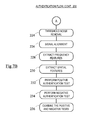
- FIG. 7 is a flowchart (split over two sheets as FIGS. 7A and 7B ) illustrating authentication of a banknote using the magnetic template generated by the process of FIG. 4 .
- FIG. 1 is a simplified schematic diagram of a media validator 12 (in the form of a banknote validator) for implementing a method of authenticating media inserted therein according to one embodiment of the present invention.
- the banknote validator 12 comprises a housing 13 supporting a transport mechanism 15 in the form a train of pinch rollers comprising upper pinch rollers 15 a aligned with lower pinch rollers 15 b , extending from an entrance port 16 to a capture port 18 .
- the entrance and capture ports 16 , 18 are in the form of apertures defined by the housing 13 . In use, the capture port 18 would typically be aligned with parts of a depository or recycler module.
- the pinch rollers 15 a,b guide a media item (in this embodiment a banknote) 20 short edge first through an examination area 22 defined by a gap between adjacent pinch roller pairs. While the banknote 20 is being conveyed through the examination area 22 , the banknote 20 is illuminated selectively by illumination sources 24 (not illustrated in detail).
- the illumination sources 24 are provided for banknote validation and other functions of the banknote validator 12 (for example, banknote identification, counterfeit detection, stain detection, and the like), as is known to those of skill in the art.
- An optical lens 26 focuses light transmitted through the banknote 20 to an optical imager 28 (in this embodiment a CIS sensor).
- a magnetic sensor array 30 is provided at the examination area 22 .
- This array 30 comprises six magnetic read heads (not shown individually) disposed in a linear array extending across a path over which the banknote 20 is transported. As such, when the banknote 20 passes over the magnetic sensor array 30 , the six read heads extend over the width (which is the dimension parallel to the short edge) of the banknote 20 .
- the banknote validator 12 includes a data and power interface 32 for allowing the banknote validator 12 to transfer data to an external unit, such as an ATM (not shown) a media depository or recycler (not shown), or a PC (not shown), and to receive data, commands, and power therefrom.
- an external unit such as an ATM (not shown) a media depository or recycler (not shown), or a PC (not shown)
- the banknote validator 12 would typically be incorporated into a media depository or recycler module, which would typically be incorporated into an ATM.
- the banknote validator 12 also has a controller 34 including a digital signal processor (DSP) 36 and an associated memory 38 .
- the controller 34 controls the transport mechanism 15 , the illuminating source 24 , the CIS sensor 28 , and the magnetic sensor array 30 .
- DSP digital signal processor
- the controller 34 also collates and processes data captured by the image sensor 28 , and the magnetic sensor array 30 , and communicates this data and/or results of any analysis of this data to the external unit via the data and power interface 32 .
- the media validator 12 transports banknotes at approximately 700 mm per second.
- Each magnetic read head in the magnetic sensor array 30 measures approximately 5800 readings per second.
- each magnetic read head produces a signal having over a thousand data points for a typical banknote.
- Each magnetic read head is referred to herein as a channel, so that this embodiment has six channels.
- FIG. 2 is a flowchart 100 illustrating pre-processing steps performed by the banknote validator 12 (as controlled by the DSP 36 ) to create a banknote authentication template for a specific denomination and orientation of banknote.
- the specific denomination relates to a denomination and series (for example, a series two United States twenty dollar bill).
- the orientation relates to one of four possible orientations: front forward, front back, rear forward, and rear back. Thus, for each specific denomination, four templates are required (one for each orientation). Only four orientations are required because banknote validators are typically designed to receive a banknote either long edge first or short edge first, but not both.
- the combination of a banknote denomination, series, and orientation is referred to herein as a “banknote type”.
- a template is created by analyzing a relatively large number of genuine banknotes (for example one hundred banknotes) of the same denomination and series. This large number of banknotes is referred to as the training set. Using a relatively large training set enables the template to take account of variations between authentic banknotes that are ostensibly identical.
- Four templates will be created from each training set; one template for each orientation. To create a template for one orientation, each banknote in that training set is inserted in that orientation.
- a banknote 20 from the training set is inserted into the validator 12 , which the banknote validator 12 receives (step 102 ).
- the banknote 20 is inserted in the orientation for which a template is being created.
- the controller 34 then transports the banknote 20 to the examination area 22 (step 104 ) and causes the CIS sensor 28 to capture an image of the banknote 20 (step 106 ) and the magnetic sensor array 30 to capture analogue signals (one from each magnetic read head) from the banknote 20 (step 108 ).
- the controller 34 operates on and processes the image created by the CIS sensor 28 , but how this is performed is not relevant to this embodiment so will not be described in detail herein.
- the controller 34 operates on the analogue signals from the magnetic sensor array 30 to reduce noise introduced by the media validator 12 (step 110 ).
- the method used to reduce system noise uses Fourier spectral analysis to identify the valid frequency range.
- the valid frequency range can be identified as follows.
- a Fast Fourier Transform (FFT) operation can be used to conduct signal spectral analysis. FFT is first performed on signals that may contain noises. Then the power spectral density is computed using the complex conjugate of the discrete Fourier transform output. This provides a measurement of the energy at various frequencies. Finally the frequency range that corresponds to the strong power spectral densities is selected. The higher a power peak is, the stronger the corresponding frequency that is contained in the signal.
- FFT Fast Fourier Transform
- FFT and subsequent inverse FFT operations are then used to remove the frequency components outside the valid frequency range [Fs_start, Fs_end].
- FFT function and the Inverse FFT (IFFT) function are implemented using a fixed length of the next power of two up from the signal length (for example, if the signal length is 783 points, the next power of two up is 1024).
- the FFT and IFFT functions are implemented as follows (sub-steps (i) to (iv)).
- x is the raw signal in time domain
- Y is the discrete FFT coefficients in the frequency domain
- I 1 floor ⁇ ( FS_start fs / n + 1 )
- I 2 floor ⁇ ( FS_end fs / n + 1 )
- n is the signal length and transform length
- fs is the sensor sampling frequency
- next step is to down average the filtered signals (step 112 ).
- a raw magnetic signal from a read head in the magnetic sensor array 30 typically has more than 1000 sample points when a banknote is measured. Down averaging is used to reduce this number of sample points (that is, to reduce the signal length). This has the advantage of averaging out noise from the signal. It also has the advantage of reducing the computational cost. Down averaging is implemented in this embodiment by averaging every ⁇ sample points from a channel (or read head), where ⁇ can be selected based on the sampling rate. In this embodiment, ⁇ was selected as “11”. This is performed for all six read heads in the magnetic sensor array 30 .
- the next step is to normalize the signal length from all of the read heads in the magnetic sensor array 30 so that each of the signal lengths matches the length Ln of a standard banknote of that denomination and series (step 114 ). This is performed because the length of a magnetic signal varies between banknotes, and may even vary between read heads in the magnetic sensor array 30 for the same banknote.
- Normalizing the length of the magnetic signals may be implemented by using data captured by the CIS sensor 28 .
- an image from the CIS sensor 28 may be processed to identify the actual starting and actual ending points of the banknote. These actual starting and ending points may be used to crop the signal lengths to the standard length Ln.
- the standard length Ln may be calculated using the sensor sampling frequency fs (Hz), banknote transport speed Dv (mm/s), and the theoretical note length L (mm) for a given currency denomination.
- the minimal theoretical sample size Ns for the banknote can be obtained using the equation:
- Ns fs ⁇ ( L - ⁇ ) Dv ,
- ⁇ is a small artificial tolerance introduced to reflect the fact that many circulated banknotes are slightly shorter than the theoretical note length.
- the value of ⁇ is selected as 1.
- the magnetic signal can be cropped to the new length (in data points) Ns by removing those data points that extend beyond half of the data points in each direction from the mid-point (that is, removing the head and tail of the magnetic signal).
- ⁇ is the same parameter used in the down average step; and the function floor(•) rounds its input value down to the next smallest integer.
- the next step is to subtract the mean value for each magnetic signal from each magnetic signal (step 116 ).
- the mean values of magnetic signals from genuine and counterfeit banknotes are at similar level in the banknote validator 12 ; therefore, it is beneficial to subtract the mean value of each signal from that signal.
- the mean subtraction was chosen over a full standardization. The latter means that in addition to subtracting the mean value of each signal from that signal, the signal amplitudes are divided by the standard deviation for that signal so that the standardized signal will have a mean of zero and a standard deviation of one.
- FIGS. 3 a to 3 c illustrate the effect of this system noise filtering step (that is, step 110 ), the down averaging step (step 112 ), and the mean value subtraction step (step 116 ).
- FIG. 3 a is a graph illustrating raw magnetic signals recorded by one magnetic read head (one channel) from white paper, with the x-axis showing the sample points and the y-axis showing the signal intensity in arbitrary units.
- FIG. 3 b is a graph illustrating the down averaged (and mean subtracted) raw magnetic signals shown in FIG. 3 a , but without filtering for system noise. When the magnetic signals of FIG. 3 a are down averaged and mean subtracted, the signal intensity averages at approximately zero, as shown in FIG. 3 b .
- FIG. 3 c is a graph illustrating the down averaged and mean subtracted raw magnetic signals shown in FIG. 3 b , but with the system noise filtering of step 110 applied to the raw signal prior to the down average step 112 . Clearly, most of the noises have been eliminated because of the noise filtering of step 110 .
- a threshold noise removal step involves selecting a threshold ⁇ so that any value within the range of [ ⁇ , ⁇ ] is set to zero. This filters out small noise components, particularly in magnetic free areas of a channel.
- the next step is to check if there are any more banknotes to be measured (step 120 ). If there are more banknotes in the set of training banknotes, then the flow returns to step 102 and is repeated by inserting another banknote from the training set in the same orientation as the banknote that was just processed.
- step 122 If there are no more banknotes in the set of training banknotes (that is, if all of the banknotes in the training set have been measured), then the pre-processing flow ends (step 122 ).
- the controller 34 then implements a magnetic template generation process 140 , as shown in FIG. 4 .
- the results of the training set creation process 100 for one orientation of the training set are collated (step 142 ).
- the controller 34 detects valid signal channels from the training set data (step 144 ). This is performed because some banknotes contain little or no magnetic information in certain areas of the banknote. For example, only one or two (sometimes none) of the channels may show valid signals for Canadian dollars because Canadian dollars contain very few magnetic features.
- Detecting valid channels may be implemented manually (for example, by an operator removing any channel data that does not indicate that any magnetic information is present). However, it is more efficient to implement this automatically.
- automatic detection of magnetic signal data from a read head is performed as follows (sub-steps (i) to (iv) below).
- ⁇ is selected as 10.
- the other read head signals (that is, the signals from those read heads that produced no valid magnetic signals for that denomination type) can be discarded for the purposes of creating a magnetic template, although they will be listed in the magnetic template as having no magnetic signal.
- the next step is to create a reference signal from each magnetic read head that generated valid magnetic signals (step 146 ).
- the controller 34 calculates a reference signal that is the average of the magnetic signals from that magnetic channel for all banknotes in the training set for that orientation.
- a reference signal that is the average of the magnetic signals from that magnetic channel for all banknotes in the training set for that orientation.
- the next step is to align the valid signals from the same read head with the corresponding reference signal for that read head (step 150 ).
- step 150 aligns the valid signals from the same read head with the corresponding reference signal for that read head.
- the next step is to perform feature extraction (step 152 ) from each of the aligned signals.
- This step has two sub-processes.
- the first sub-process relates to spatial features; the second sub-process relates to frequency features.
- An entire aligned signal is not particularly useful for classification purposes because it is too complex. For this reason, it is helpful to identify features of the aligned signal (for example, spatial features) and to derive a value for those identified features. This derived value can then be compared with a value derived from corresponding features of a signal from a banknote being authenticated. For example, all non-zero values and their corresponding locations can be used as the spatial features.
- Spatial feature extraction involves, (i) specifying the similarity measure (spatial domain model) to be used for the valid channels of the banknote 20 , and (ii) for each aligned signal for each valid channel, deriving (using the specified similarity measure) the similarity scores between the aligned signal and the reference signal.
- the similarity measure spatial domain model
- each similarity score being a measure of the similarity between spatial features in the reference signal for that channel and spatial features in one of the aligned signals.
- there would be a total of 400 similarity scores 100 scores per channel, and four valid channels).
- the specified similarity measure may be selected from a number of different similarity measures (or models). Any model that is capable of inferring a degree of spatial match between two different one-dimensional signals can be used as the similarity measure.
- These similarity measures include: (i) a Pearson Product-Moment Correlation Coefficient (PPMCC) model, described, for example, in J. L. Rodgers and W. A. Nicewander, Thirteen ways to look at the correlation coefficient, The American Statistician, 42(1): 59-66, February 1988; (ii) the Intersection Score adapted from the color histogram intersection matching in M. J. Swain and D. H.
- the Intersection Score is used as the specified similarity measure.
- the normalized Intersection Score h between the reference signal x and the aligned signal y is:
- this score is averaged across all valid channels for that banknote. For example, if there are 100 banknotes in a training set, and four valid channels, one Intersection Score is produced for each banknote. This Intersection Score is an average of the four similarity scores from the four valid channels (one score from each channel) of this banknote. In total, 100 similarity scores will be generated for the 100 banknotes in the training set. These 100 similarity scores will be used to calculate positive test parameters (described in more detail below in step 154 ).
- the type of spatial feature is also specified by the template.
- the Intersection Score is the type of spatial feature that is used for all valid channels (however, in other embodiments, different types of spatial feature may be used for different valid channels in the same template).
- Frequency feature extraction involves, (i) summing the aligned signals for all valid channels to create a summed signal for each banknote, (ii) applying a Fourier Transform (using an FFT algorithm) to the summed signal to produce coefficients corresponding to different frequency components in the summed signal (iii) specifying the frequency components of interest from the summed signal, and (iv) extracting those frequency components from the summed signal.
- n may be in the range of 5 to 50.
- frequency components for all banknotes in the training set. These frequency components are “stacked together” as a training feature set. For example, if there are 100 notes in the training set, and 6 frequency components were extracted from each note; the training feature set would be a 100 row by 6 column matrix.
- the next step is to calculate the positive test parameters for the classifier (step 154 ). Parameters will be calculated for both the spatial features and also the frequency features.
- a thresholding test is used to implement a positive test for the spatial features.
- a number of different thresholding tests could be used. Two suitable thresholding tests are: (i) a crude adaptive threshold, and (ii) a bootstrap threshold.
- the crude adaptive threshold involves sorting the spatial feature values (that is, the similarity scores obtained in step 152 ) of all of the banknotes in the training set in ascending order to produce r sorted .
- a suitable value for ⁇ is in the range of 0.001 to 0.01, corresponding to 0.1% to 1% of theoretical false reject rates.
- the Bootstrap threshold involves employing the bootstrap technique (described in C. He, M. Girolami and G. Ross. Employing optimized combinations of one - class classifiers for automated currency validation . Pattern Recognition, 37: 1085-1096, 2004.) on the training set to estimate the numerical distribution of the test statistic for the null hypothesis that a test sample is from the same class as the training set.
- the calculated threshold ⁇ is stored in the template for that banknote type.
- a D 2 test is used to implement a positive test for the frequency features.
- the method for training a D 2 test for frequency features is described in U.S. Pat. No. 7,639,858, which is incorporated herein by reference, and also in “Multivariate Statistical Methods” (third edition), by Morrison, McGraw-Hill Publishing Company, New York (1990).
- the template stores the parameters for the D 2 test that are obtained during training.
- the thresholding test for spatial features or the D 2 test for frequency features can be used as a positive test for banknote authentication.
- Preliminary results indicate that the thresholding test for spatial features works well for any currencies; whereas, the D 2 test works particularly well for currencies that have a significant number of magnetic features.
- the next step is to calculate the negative test parameters for the classifier (step 156 ), which is illustrated in FIG. 5 .
- the first sub-step (step 162 ) is to detect the magnetic free zones (MFZ) for each channel (not just the valid channels) and record their starting and ending coordinates [idx_s i idx_e i ]. This is done for each banknote in the training set.
- MFZ magnetic free zones
- a magnetic free zone is defined as a continuous section of the signal where no significant magnetic response is present; that is, where all the signal points have a value of zero (in the signals after step 118 ) or within a small pre-defined range.
- a candidate MFZ qualifies only if its length is longer than certain pre-defined threshold (for example, 20% of the banknote length).
- the second sub-step (step 164 ) is to record the three longest MFZs for each channel. Since only qualified MFZs are recorded, sometimes there may be less than three or even none of MFZs for certain banknote types due to their magnetic printing design. The reason that only the three longest MFZs are selected is to minimize the storage and computational cost. For channels that were deemed not to have any valid magnetic signals (in step 144 above), the whole channel length is deemed to be an MFZ.
- the third sub-step (step 166 ) is to detect, for each channel, the common MFZs for that channel across all of the banknotes in the training set.
- all banknotes in the training set are of the same denomination and series, nevertheless, circulated banknotes vary by size (length and width) and condition.
- the starting and ending coordinates of the candidate MFZs detected for each channel may vary from one banknote in the training set to the next.
- Detecting the common MFZs is implemented using clustering technique (for example, any versions of K-Means, described in A. Likas, N. Vlassis and J. J. Verbeek.
- the global k - means clustering algorithm . Pattern Recognition, 36: 451-461, 2003) can be applied to identify the common MFZs.
- This third sub-step includes the following sub-steps, illustrated in FIG. 6 .
- the first sub-step is to use clustering techniques to group all candidate MFZs into multiple sub-groups according to their similarities (distances) (step 172 ).
- MFZ representatives Discard any MFZ representatives that are shorter than a pre-defined threshold, (for example, 20% of the banknote length) (step 178 ).
- a pre-defined threshold for example, 20% of the banknote length
- the longest three MFZ representatives are deemed to be the common MFZs of all the banknotes in the training set for that channel, and their starting and ending coordinates are stored in the template for that channel, together with a false ratio threshold for use with the MFZs (step 182 ).
- the false ratio threshold represents the acceptable level of non-zero magnetic points in a MFZ, and is normally greater than 0 and less than 0.15. Setting the false ratio threshold too high may increase the counterfeit accepting risks; while setting this value too low may lead to high false rejection of genuine notes.
- a template has been created that includes: a reference signal for each valid channel; a list of the valid channels; a calculated threshold (derived from the similarity score) for the spatial feature of each valid channel; optionally frequency components, a standard length Ln for that banknote, a spatial feature type for the valid channels, or for each valid channel if a different spatial feature is used for each channel, the parameters for the D 2 test (only if the frequency components are used) that were obtained during training, up to three MFZs for each channel (valid and invalid) including start and end points of each MFZ, and a false ratio threshold for use with the MFZs.
- FIG. 7 is a flowchart 200 illustrating steps performed by the banknote validator 12 .
- this process 200 relates only to the magnetic authentication process.
- Banknote validators may perform a number of other processes including recognition (to identify the banknote currency, denomination and orientation) optical authentication, fitness assessment, and the like.
- a final decision on authentication may be based on a number of different factors, such as magnetic authentication, optical authentication, and the like.
- the first four steps of the magnetic authentication process 200 are identical (or at least very similar) to the first four steps of the training set creation process 100 .
- test banknote a banknote to be authenticated (the “test banknote”) is inserted into the validator 12 , which the banknote validator 12 receives (step 202 ).
- the test banknote may be inserted in any orientation.
- the controller 34 then transports the test banknote to the examination area 22 (step 204 ) and causes the CIS sensor 28 to capture an image of the test banknote (step 206 ) and the magnetic sensor array 30 to capture analogue signals (one from each magnetic read head) from the test banknote (step 208 ).
- Banknote recognition (step 210 ) is then performed to identify the currency, denomination, and orientation of the test banknote. This is implemented using the image of the test banknote captured in step 206 .
- the template for that banknote type is accessed and information about the valid magnetic channels is retrieved (step 212 ).
- Those magnetic signals corresponding to channels that do not produce valid magnetic signals are discarded (step 214 ).
- the controller 34 operates on the remaining analogue signals from the magnetic sensor array 30 (that is, on the valid channels) to reduce noise introduced by the media validator 12 (step 216 ). This is implemented using the same technique, and the same parameters, as described in step 110 for the training set process 100 (that is, Fourier spectral analysis is used over the valid frequency range [Fs_start, Fs_end]).
- the next step is to down average the noise-reduced signals (step 218 ) in the same way and using the same parameters as described in step 112 for the training set process 100 (that is, by averaging every ⁇ sample points from a channel (in this embodiment ⁇ was selected as “11”) for each of the six read heads in the magnetic sensor array 30 ).
- the next step is to calibrate (crop) the signal length from all of the valid read heads in the magnetic sensor array 30 to the standard length Ln (step 220 ) in the same way as described in step 114 for the training set process 100 .
- the standard length Ln for that banknote is retrieved from the template and used in this calibration step.
- the mean value for each magnetic signal is then subtracted from each valid magnetic signal (step 222 ) in the same way as described in step 116 for the training set process 100 .
- a threshold noise removal step (step 224 ) is then performed. Again, the same technique is used in this step 220 as was used in the threshold noise removal step (step 118 ) of the training set process 100 .
- the values [ ⁇ , ⁇ ] used may be the same as those used in the training set, or may be determined adaptively by using a small percentage of the maximum amplitude M of the measured signal.
- a signal alignment process (step 226 ) is then performed. This involves, for each valid channel, retrieving from the template a reference signal for that valid channel, and minimizing the RMS error. This is implemented by shifting the calibrated length signal along the sampling position axis. For each shift (that is, for each shift by one sampling position), the RMS value between the shifted signal and the reference signal is calculated. After evaluating all possible shifts within a defined the range (for example, from minus ten sampling positions to plus ten sampling positions), the shift with the minimal RMS value is selected; and the corresponding shifted signal is regarded as the aligned signal for that channel.
- a frequency feature extraction process is performed (step 228 ). Although frequency feature extraction is described at this point, it could be performed at any time after the magnetic signals have been captured (step 208 ) because the frequency components are not affected by shifting and alignment.
- frequency feature extraction involves: (i) summing the aligned signals for all valid channels to create a summed signal for the test banknote, (ii) applying a Fourier Transform (as described with reference to step 152 in the template generation process 140 ) to the summed signal to produce coefficients corresponding to different frequency components in the summed signal, (iii) accessing the template to ascertain the frequency components of interest, and (iv) extracting those frequency components of interest from the summed signal.
- a Fourier Transform as described with reference to step 152 in the template generation process 140
- a spatial feature extraction process can be implemented (step 230 ).
- Spatial feature extraction involves, (i) retrieving a spatial feature type from the template (in this embodiment it is the Intersection Score), and (ii) for each aligned signal for each valid channel, deriving (using the Intersection Score) the similarity scores between the aligned signal and the reference signal.
- the Intersection Score is derived in the same was as described with reference to step 152 of the template generation process 140 .
- the next step is to perform a positive authentication test (step 232 ).
- This test is to ensure that a magnetic signal has magnetic information in the correct locations.
- the first part (the spatial part) of the positive authentication test involves retrieving from the template the calculated threshold for the spatial feature of each valid channel.
- a thresholding test is then performed. This may be performed by averaging all of the similarity scores and comparing them with the average of the retrieved thresholds.
- the individual retrieved similarity scores are used. This is implemented by comparing the similarity score of each selected channel to the corresponding threshold for that channel (retrieved from the template).
- the results for each of the individual channels are then combined together to provide the final decision.
- majority voting is used.
- the test banknote will pass the (or this part of the) positive authentication test if the majority of the channels have a feature value greater than or equal to the threshold; otherwise the test banknote will fail the positive authentication test.
- the second part (the frequency part) of the positive authentication test involves using a D 2 frequency test, as described in U.S. Pat. No. 7,639,858 assigned to NCR Corporation.
- the test banknote is deemed counterfeit if it fails this test.
- the next step is to perform a negative authentication test (step 234 ).
- the negative test begins by accessing the template to retrieve, for each valid channel, the longest three MFZ representatives, including their starting and ending coordinates.
- the banknote validator 12 calculates a ratio of non-zero points to all points along the length of the magnetic-free zone (for example, if there are 50 points in the first MFZ for a channel, and 20 of these points are non-zero points, then the ratio is 0.40).
- the banknote validator 12 then calculates an overall average of the ratios for all magnetic-free zones (in all channels). This is referred to as the overall false ratio. If the overall false ratio is less than or equal to a ratio threshold (retrieved from the template), then the test banknote passes this negative test; otherwise the test banknote fails this negative test.
- the next step is to combine the positive and negative authentication tests to classify the test banknote as either genuine or counterfeit (step 236 ).
- the results may be combined by using a unanimous vote so that the test banknote is only passed as genuine if the test banknote passes both the positive test and the negative test.
- the results are combined by using weighting factors to reflect the characteristics of individual banknotes.
- the combined results are based on a normalized positive result score multiplied by a weighting factor ( ⁇ ) plus a normalized negative result score multiplied by one minus ⁇ (where ⁇ is between zero and one).
- the weighting factor ( ⁇ ) may be low such that a positive test is not given much significance.
- the positive authentication test and the negative authentication test may be combined with other authentication tests, for example, optical authentications tests, so that the test banknote is authenticated based on a combination of different tests (both magnetic and non-magnetic).
- the training process can be done automatically. No counterfeit data is required for training (that is, for template generation).
- the process is adaptive, so it can be applied to any currencies (or non-banknote media).
- the process is fast and does not require intensive computation.
- the transport mechanism 15 may comprise a different arrangement, for example, one or more of skid plates, endless belts, gear trains, and the like.
- media items may be items other than banknotes, such as tickets, coupons, passports, or the like.
Landscapes
- Physics & Mathematics (AREA)
- General Physics & Mathematics (AREA)
- Health & Medical Sciences (AREA)
- General Health & Medical Sciences (AREA)
- Toxicology (AREA)
- Engineering & Computer Science (AREA)
- Computer Vision & Pattern Recognition (AREA)
- Multimedia (AREA)
- Theoretical Computer Science (AREA)
- Inspection Of Paper Currency And Valuable Securities (AREA)
Abstract
Description
-
- (i) For each signal carry out the Fast Fourier Transform
Y=FFT(x),
- (i) For each signal carry out the Fast Fourier Transform
-
- (ii) Calculate the indices (I) (starting from 1) of the FFT components corresponding to the valid frequency range [Fs_start, Fs_end].
I 3 =n−I 1+1
I 4 =n−I 2+1
-
- (iii) Set the FFT coefficients Y to zero except for the indices ([I1, I2] and [I4, I3]) that are corresponding to the valid frequency range.
- (iv) Carry out the IFFT on the modified FFT coefficients Y1 to obtain the filtered signal in the time domain.
x_filtered=real(IFFT(Y 1))
Ns=floor(Ns/θ)
-
- (i) For each
banknote 20 in the training set, and for each read head that measured thatbanknote 20, use the pre-processed data to calculate the signal range λk i, (that is, the difference between the maximum and minimum values of the magnetic signal for that read head and banknote 20). - (ii) Calculate the average range value
λ k of the training set for each channel. - (iii) If the average range
λ k is greater than or equal to ξ, where ξ is a small threshold (that is,λ k≧ξ), the corresponding channel (read head) is a valid channel (that is, it contains magnetic information). - (iv) If the average range
λ k<ξ, the corresponding channel (read head) is not a valid channel (that is, it contains no magnetic information).
- (i) For each
Claims (16)
Priority Applications (1)
| Application Number | Priority Date | Filing Date | Title |
|---|---|---|---|
| US13/919,064 US9245399B2 (en) | 2013-06-17 | 2013-06-17 | Media authentication |
Applications Claiming Priority (1)
| Application Number | Priority Date | Filing Date | Title |
|---|---|---|---|
| US13/919,064 US9245399B2 (en) | 2013-06-17 | 2013-06-17 | Media authentication |
Publications (2)
| Publication Number | Publication Date |
|---|---|
| US20140369590A1 US20140369590A1 (en) | 2014-12-18 |
| US9245399B2 true US9245399B2 (en) | 2016-01-26 |
Family
ID=52019273
Family Applications (1)
| Application Number | Title | Priority Date | Filing Date |
|---|---|---|---|
| US13/919,064 Active 2034-01-18 US9245399B2 (en) | 2013-06-17 | 2013-06-17 | Media authentication |
Country Status (1)
| Country | Link |
|---|---|
| US (1) | US9245399B2 (en) |
Families Citing this family (7)
| Publication number | Priority date | Publication date | Assignee | Title |
|---|---|---|---|---|
| US20160077956A1 (en) * | 2014-09-11 | 2016-03-17 | Wipro Limited | System and method for automating testing of software |
| DE202015002913U1 (en) * | 2015-04-22 | 2015-06-18 | Daniel Bossert | Test System |
| CN104802514B (en) | 2015-05-13 | 2017-12-22 | 广州广电运通金融电子股份有限公司 | A kind of flaky medium detection means of surface mount foreign matter |
| CN105427446A (en) * | 2015-11-06 | 2016-03-23 | 东方通信股份有限公司 | Authentic identification method for paper money based on magnetic signal |
| US10275971B2 (en) * | 2016-04-22 | 2019-04-30 | Ncr Corporation | Image correction |
| CN108718308A (en) * | 2018-05-10 | 2018-10-30 | 清华大学 | A kind of communication system can verify that equipment identities, method and apparatus |
| US10891820B2 (en) * | 2018-08-30 | 2021-01-12 | Ncr Corporation | Counterfeit note tracking |
Citations (8)
| Publication number | Priority date | Publication date | Assignee | Title |
|---|---|---|---|---|
| US5014325A (en) * | 1985-02-01 | 1991-05-07 | Nihon Eiwan Denshikiki Co., Ltd. | Apparatus for discriminating specified sorts of printed matters |
| US5545885A (en) * | 1992-06-01 | 1996-08-13 | Eastman Kodak Company | Method and apparatus for detecting and identifying coded magnetic patterns on genuine articles such as bank notes |
| US5761089A (en) * | 1992-07-14 | 1998-06-02 | Mcinerny; George P. | Counterfeit document detection apparatus |
| US6474548B1 (en) * | 1999-11-30 | 2002-11-05 | Diebold, Incorporated | Deposit accepting and storage apparatus and method for automated banking machine |
| US20090008451A1 (en) * | 2006-08-31 | 2009-01-08 | Star Micronics Co., Ltd. | Magnetic ink character reading apparatus and method of controlling the same |
| US20090152356A1 (en) * | 2007-12-14 | 2009-06-18 | Honeywell International Inc. | Non-contact magnetic pattern recognition sensor |
| US20130329983A1 (en) * | 2012-06-08 | 2013-12-12 | Seiko Epson Corporation | Recording media processing device, control method of a recording media processing device, and computer-readable recording medium |
| US20140367469A1 (en) * | 2011-12-13 | 2014-12-18 | Giesecke & Devrient Gmbh | Method and Apparatus for Checking Value Documents |
-
2013
- 2013-06-17 US US13/919,064 patent/US9245399B2/en active Active
Patent Citations (8)
| Publication number | Priority date | Publication date | Assignee | Title |
|---|---|---|---|---|
| US5014325A (en) * | 1985-02-01 | 1991-05-07 | Nihon Eiwan Denshikiki Co., Ltd. | Apparatus for discriminating specified sorts of printed matters |
| US5545885A (en) * | 1992-06-01 | 1996-08-13 | Eastman Kodak Company | Method and apparatus for detecting and identifying coded magnetic patterns on genuine articles such as bank notes |
| US5761089A (en) * | 1992-07-14 | 1998-06-02 | Mcinerny; George P. | Counterfeit document detection apparatus |
| US6474548B1 (en) * | 1999-11-30 | 2002-11-05 | Diebold, Incorporated | Deposit accepting and storage apparatus and method for automated banking machine |
| US20090008451A1 (en) * | 2006-08-31 | 2009-01-08 | Star Micronics Co., Ltd. | Magnetic ink character reading apparatus and method of controlling the same |
| US20090152356A1 (en) * | 2007-12-14 | 2009-06-18 | Honeywell International Inc. | Non-contact magnetic pattern recognition sensor |
| US20140367469A1 (en) * | 2011-12-13 | 2014-12-18 | Giesecke & Devrient Gmbh | Method and Apparatus for Checking Value Documents |
| US20130329983A1 (en) * | 2012-06-08 | 2013-12-12 | Seiko Epson Corporation | Recording media processing device, control method of a recording media processing device, and computer-readable recording medium |
Also Published As
| Publication number | Publication date |
|---|---|
| US20140369590A1 (en) | 2014-12-18 |
Similar Documents
| Publication | Publication Date | Title |
|---|---|---|
| US9245399B2 (en) | Media authentication | |
| US8615475B2 (en) | Self-calibration | |
| US8078875B2 (en) | Verification of authenticity | |
| US8302855B2 (en) | Banking system controlled responsive to data bearing records | |
| CA2677714C (en) | Document imaging and processing system | |
| US8682076B2 (en) | Signature generation for use in authentication and verification using a non-coherent radiation source | |
| US20150310268A1 (en) | Media item validation | |
| US20130259301A1 (en) | Stain detection | |
| US8892556B2 (en) | Optimisation | |
| US20010043140A1 (en) | Media validation | |
| CN108335402B (en) | infrared pair tube false distinguishing method of currency detector based on deep learning | |
| KR100893613B1 (en) | Method and apparatus for recognizing and counting currency notes and securities having barcodes | |
| US20020044677A1 (en) | Denomination identification | |
| JP5502111B2 (en) | Paper sheet identification device and paper sheet identification method | |
| EP3598400B1 (en) | Paper sheet image acquisition device, paper sheet processing device, and paper sheet image acquisition method | |
| US7715610B2 (en) | Method and apparatus for processing signals in testing currency items | |
| KR101232684B1 (en) | Method for detecting counterfeits of banknotes using Bayesian approach | |
| RU2280284C2 (en) | Method for determining invalid banknotes, produced by gluing together parts of banknotes and fake banknotes | |
| EP3410409B1 (en) | Media security validation | |
| KR102639183B1 (en) | Method of recognizing magnetic ink characters in ATM | |
| US10740997B2 (en) | Valuable media substrate validation | |
| JPH0814860B2 (en) | How to distinguish paper sheets | |
| Ibitoye | Fake Currency Detection using Modified Faster Region-Based Convolutional Neural Network | |
| JPH0132464B2 (en) | ||
| JPH08190649A (en) | Printed pattern deciding device |
Legal Events
| Date | Code | Title | Description |
|---|---|---|---|
| AS | Assignment |
Owner name: NCR CORPORATION, GEORGIA Free format text: ASSIGNMENT OF ASSIGNORS INTEREST;ASSIGNORS:HE, CHAO;ROSS, GARY;SIGNING DATES FROM 20130604 TO 20130606;REEL/FRAME:030621/0981 |
|
| AS | Assignment |
Owner name: JPMORGAN CHASE BANK, N.A., AS ADMINISTRATIVE AGENT, ILLINOIS Free format text: SECURITY AGREEMENT;ASSIGNORS:NCR CORPORATION;NCR INTERNATIONAL, INC.;REEL/FRAME:032034/0010 Effective date: 20140106 Owner name: JPMORGAN CHASE BANK, N.A., AS ADMINISTRATIVE AGENT Free format text: SECURITY AGREEMENT;ASSIGNORS:NCR CORPORATION;NCR INTERNATIONAL, INC.;REEL/FRAME:032034/0010 Effective date: 20140106 |
|
| STCF | Information on status: patent grant |
Free format text: PATENTED CASE |
|
| AS | Assignment |
Owner name: JPMORGAN CHASE BANK, N.A., ILLINOIS Free format text: SECURITY AGREEMENT;ASSIGNORS:NCR CORPORATION;NCR INTERNATIONAL, INC.;REEL/FRAME:038646/0001 Effective date: 20160331 |
|
| MAFP | Maintenance fee payment |
Free format text: PAYMENT OF MAINTENANCE FEE, 4TH YEAR, LARGE ENTITY (ORIGINAL EVENT CODE: M1551); ENTITY STATUS OF PATENT OWNER: LARGE ENTITY Year of fee payment: 4 |
|
| MAFP | Maintenance fee payment |
Free format text: PAYMENT OF MAINTENANCE FEE, 8TH YEAR, LARGE ENTITY (ORIGINAL EVENT CODE: M1552); ENTITY STATUS OF PATENT OWNER: LARGE ENTITY Year of fee payment: 8 |
|
| AS | Assignment |
Owner name: CITIBANK, N.A., NEW YORK Free format text: SECURITY INTEREST;ASSIGNOR:NCR ATLEOS CORPORATION;REEL/FRAME:065331/0297 Effective date: 20230927 |
|
| AS | Assignment |
Owner name: NCR VOYIX CORPORATION, GEORGIA Free format text: RELEASE OF PATENT SECURITY INTEREST;ASSIGNOR:JPMORGAN CHASE BANK, N.A., AS ADMINISTRATIVE AGENT;REEL/FRAME:065346/0531 Effective date: 20231016 Owner name: BANK OF AMERICA, N.A., AS ADMINISTRATIVE AGENT, NORTH CAROLINA Free format text: SECURITY INTEREST;ASSIGNORS:NCR ATLEOS CORPORATION;CARDTRONICS USA, LLC;REEL/FRAME:065346/0367 Effective date: 20231016 |
|
| AS | Assignment |
Owner name: CITIBANK, N.A., NEW YORK Free format text: CORRECTIVE ASSIGNMENT TO CORRECT THE DOCUMENT DATE AND REMOVE THE OATH/DECLARATION (37 CFR 1.63) PREVIOUSLY RECORDED AT REEL: 065331 FRAME: 0297. ASSIGNOR(S) HEREBY CONFIRMS THE SECURITY INTEREST;ASSIGNOR:NCR ATLEOS CORPORATION;REEL/FRAME:065627/0332 Effective date: 20231016 |