US9250573B2 - Image forming apparatus - Google Patents
Image forming apparatus Download PDFInfo
- Publication number
- US9250573B2 US9250573B2 US14/718,397 US201514718397A US9250573B2 US 9250573 B2 US9250573 B2 US 9250573B2 US 201514718397 A US201514718397 A US 201514718397A US 9250573 B2 US9250573 B2 US 9250573B2
- Authority
- US
- United States
- Prior art keywords
- developing
- developer
- photosensitive drum
- image
- grooves
- Prior art date
- Legal status (The legal status is an assumption and is not a legal conclusion. Google has not performed a legal analysis and makes no representation as to the accuracy of the status listed.)
- Active
Links
Images


Classifications
-
- G—PHYSICS
- G03—PHOTOGRAPHY; CINEMATOGRAPHY; ANALOGOUS TECHNIQUES USING WAVES OTHER THAN OPTICAL WAVES; ELECTROGRAPHY; HOLOGRAPHY
- G03G—ELECTROGRAPHY; ELECTROPHOTOGRAPHY; MAGNETOGRAPHY
- G03G15/00—Apparatus for electrographic processes using a charge pattern
- G03G15/06—Apparatus for electrographic processes using a charge pattern for developing
- G03G15/08—Apparatus for electrographic processes using a charge pattern for developing using a solid developer, e.g. powder developer
- G03G15/09—Apparatus for electrographic processes using a charge pattern for developing using a solid developer, e.g. powder developer using magnetic brush
- G03G15/0907—Apparatus for electrographic processes using a charge pattern for developing using a solid developer, e.g. powder developer using magnetic brush with bias voltage
-
- G—PHYSICS
- G03—PHOTOGRAPHY; CINEMATOGRAPHY; ANALOGOUS TECHNIQUES USING WAVES OTHER THAN OPTICAL WAVES; ELECTROGRAPHY; HOLOGRAPHY
- G03G—ELECTROGRAPHY; ELECTROPHOTOGRAPHY; MAGNETOGRAPHY
- G03G15/00—Apparatus for electrographic processes using a charge pattern
- G03G15/06—Apparatus for electrographic processes using a charge pattern for developing
- G03G15/08—Apparatus for electrographic processes using a charge pattern for developing using a solid developer, e.g. powder developer
- G03G15/0806—Apparatus for electrographic processes using a charge pattern for developing using a solid developer, e.g. powder developer on a donor element, e.g. belt, roller
- G03G15/0818—Apparatus for electrographic processes using a charge pattern for developing using a solid developer, e.g. powder developer on a donor element, e.g. belt, roller characterised by the structure of the donor member, e.g. surface properties
-
- G—PHYSICS
- G03—PHOTOGRAPHY; CINEMATOGRAPHY; ANALOGOUS TECHNIQUES USING WAVES OTHER THAN OPTICAL WAVES; ELECTROGRAPHY; HOLOGRAPHY
- G03G—ELECTROGRAPHY; ELECTROPHOTOGRAPHY; MAGNETOGRAPHY
- G03G15/00—Apparatus for electrographic processes using a charge pattern
- G03G15/06—Apparatus for electrographic processes using a charge pattern for developing
- G03G15/08—Apparatus for electrographic processes using a charge pattern for developing using a solid developer, e.g. powder developer
- G03G15/09—Apparatus for electrographic processes using a charge pattern for developing using a solid developer, e.g. powder developer using magnetic brush
- G03G15/0921—Details concerning the magnetic brush roller structure, e.g. magnet configuration
- G03G15/0928—Details concerning the magnetic brush roller structure, e.g. magnet configuration relating to the shell, e.g. structure, composition
-
- G—PHYSICS
- G03—PHOTOGRAPHY; CINEMATOGRAPHY; ANALOGOUS TECHNIQUES USING WAVES OTHER THAN OPTICAL WAVES; ELECTROGRAPHY; HOLOGRAPHY
- G03G—ELECTROGRAPHY; ELECTROPHOTOGRAPHY; MAGNETOGRAPHY
- G03G2215/00—Apparatus for electrophotographic processes
- G03G2215/06—Developing structures, details
- G03G2215/0602—Developer
- G03G2215/0604—Developer solid type
- G03G2215/0607—Developer solid type two-component
- G03G2215/0609—Developer solid type two-component magnetic brush
-
- G—PHYSICS
- G03—PHOTOGRAPHY; CINEMATOGRAPHY; ANALOGOUS TECHNIQUES USING WAVES OTHER THAN OPTICAL WAVES; ELECTROGRAPHY; HOLOGRAPHY
- G03G—ELECTROGRAPHY; ELECTROPHOTOGRAPHY; MAGNETOGRAPHY
- G03G2215/00—Apparatus for electrophotographic processes
- G03G2215/08—Details of powder developing device not concerning the development directly
- G03G2215/0855—Materials and manufacturing of the developing device
- G03G2215/0858—Donor member
- G03G2215/0861—Particular composition or materials
Definitions
- the present invention relates to an image forming apparatus for forming an image using an electrophotographic process.
- Japanese Laid-Open Patent Application 2000-321864 discloses an image forming apparatus including a developing roller having V-shaped grooves, each extending in an axial direction, provided at a plurality of positions with respect to a circumferential direction.
- a developing roller having V-shaped grooves, each extending in an axial direction, provided at a plurality of positions with respect to a circumferential direction.
- a principal object of the present invention is to provide an image forming apparatus capable of suppressing generation of image density non-uniformity, on a surface of an image bearing member, due to a plurality of grooves formed on an outer surface of a developing roller with a predetermined interval with respect to a circumferential direction.
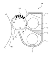
- FIG. 1 is a sectional view of an image forming apparatus according to Embodiment 1.
- FIG. 2 is a sectional view of a developing device.
- FIG. 3 is a sectional view of a modified example of the developing device.
- FIG. 4 is a sectional view of the developing device.
- FIG. 5 (a) and (b) are sectional views each showing grooves formed on a developing sleeve.
- FIG. 6 (a) and (b) are sectional views each showing a modified example of the grooves formed on the developing sleeve.
- FIG. 7 is a schematic view showing a state in which a developer is fed between the developing sleeve and a photosensitive drum.
- FIG. 8 is a sectional view showing a state in which the developer is carried on the developing sleeve.
- FIG. 9 is a graph showing a relationship between a developer density on the developing sleeve between grooves with respect to a developer feeding direction and a density on the photosensitive drum.
- FIG. 10 is a sectional view stirring chamber showing a groove range in which a point A on the photosensitive drum is overtaken in a developing region.
- FIG. 11 is a sectional view stirring chamber showing a groove range in which a point B spaced from the point A on the photosensitive drum by a distance shorter than w/ ⁇ is overtaken in the developing region.
- FIG. 12 is a sectional view stirring chamber showing a groove range in which a point C spaced from the point A on the photosensitive drum by a distance long than w/ ⁇ and shorter than (2p ⁇ L)/ ⁇ is overtaken in the developing region.
- FIG. 13 is a sectional view stirring chamber showing a groove range in which a point D spaced from the point A on the photosensitive drum by a distance longer than (2p ⁇ L)/ ⁇ and shorter than (2p+w ⁇ L)/ ⁇ is overtaken in the developing region.
- FIG. 14 is a sectional view stirring chamber showing a groove range in which a point E spaced from the point A on the photosensitive drum by a distance longer than (2+w ⁇ L)/ ⁇ and shorter than p/ ⁇ is overtaken in the developing region.
- FIG. 15 is a graph showing the number of times the groove passes through each of the points when p+w L ⁇ 2p holds.
- FIG. 17 is a graph showing the number of times the groove overtakes an arbitrary point on the photosensitive drum.
- FIG. 18 (a) and (b) are graphs each showing a relationship between a density on a transfer material and a position of the transfer material, in which (a) shows Comparison Example, and (b) shows Embodiment 1.
- FIG. 19 is a graph in which density non-uniformity peak values at portions corresponding to a period of grooves appearing on the photosensitive drum in the case where only a peripheral speed ratio ⁇ is finely changed are plotted while fixing a diameter of the photosensitive drum, a diameter of the developing sleeve, a shape of grooves and the like.
- FIG. 1 is a sectional view of an image forming apparatus 100 according to Embodiment 1.
- the image forming apparatus 100 shown in FIG. 1 is a full-color image forming apparatus.
- Stations Y, M, C and K have substantially the same constitution and form images of yellow (Y), magenta (M), cyan (C) and black (K), respectively, for a full-color image.
- a developing device 104 is used in common to developing devices 104 Y, 104 M, 104 C and 104 K at the stations Y, K, C and K. This is true for reference numerals 10 , 20 , 21 , 22 , 23 , 26 and 30 described later.
- a photosensitive drum 10 as an image bearing member is provided opposed to a developing roller 30 and is a member for bearing an electrostatic image.
- the photosensitive drum 10 is rotatably provided, and is electrically charged uniformly by a primary charger 21 and then is exposed to light modulated depending on an information signal by a light emitting element 22 such as a laser, so that an electrostatic image is formed.
- the electrostatic image is visualized as a toner image (developer image) by the developing device 104 in a process described later.
- the toner image is transferred, every station by a first transfer charger 23 , onto a transfer material 27 as a recording material fed by a transfer material feeding sheet 24 , and thereafter is fixed by a fixing device 25 to obtain a permanent image.
- a transfer residual toner remaining on the photosensitive drum 10 is removed by a cleaning device 26 .
- the toner in an amount corresponding to that of the toner contained in the developer T consumed by image formation is supplied from a toner supplying container 20 .
- the present invention is also applicable to a constitution in which an intermediary transfer member is provided in place of the transfer material feeding sheet 24 .
- the respective color toner images are, after being primary-transferred from the respective photosensitive drums 10 Y, 10 M, 10 C and 10 K onto the intermediary transfer member, collectively secondary-transferred onto the transfer material.
- the toner contains colored particles made up of a binder resin, a coloring agent, colored resin particles containing other additives as desired, and external additives such as fine powder of colloidal silica. Further, the toner is formed of a negatively chargeable polyester resin material and is 7.0 ⁇ m in volume-average particle size in this embodiment.
- the material for the carrier surface-oxidized or non-oxidized particles of a metallic substance, such as iron, nickel, cobalt, manganese, chrome, rare-earth metal and their alloys, or oxidized ferrite, and the like, can be suitably used.
- the method for manufacturing these magnetic particles is not particularly limited.
- the carrier which was 40 ⁇ m in volume average particle size, 5 ⁇ 10 8 ⁇ .cm in volume resistivity, and 260 emu/cc in magnetization was used.
- FIG. 2 is a sectional view of the developing device 104 .
- the developing device 104 in this embodiment includes a developing container 2 , in which the two-component developer containing a non-magnetic toner and a magnetic carrier is accommodated, and a developing roller 30 and a regulating blade 9 .
- the developing roller 30 is a developer carrying member capable of carrying the developer T containing the toner and the carrier.
- the developing roller 30 includes a developing sleeve 8 in which a magnet roller 8 ′ having a plurality of magnetic poles disposed along a circumferential direction is provided.
- the developing roller 30 is provided with a plurality of grooves each extending in an axial direction with a predetermined interval with respect to the circumferential direction on an outer surface thereof.
- the image forming apparatus 100 causes a developing bias including an AC electric field to act on a developing region which is an opposing portion between the developing roller 30 and the photosensitive drum 10 , so that the electrostatic image on the photosensitive drum 10 is developed with the developer T carried on the developing roller 30 .
- the regulating blade 9 is provided opposed, and is a member for regulating, a layer thickness of the developer carried on the surface of the developing sleeve 8 .
- the inside of the developing container 2 is vertically partitioned substantially at a central portion into a developing chamber 3 and a stirring chamber 4 by a partition wall 7 which extends in the direction perpendicular to the surface of the drawing sheet of FIG. 2 , and the developer T is accommodated in the developing chamber 3 and the stirring chamber 4 .
- first and second feeding screws 5 and 6 are provided, respectively, as a circulating means for circulating the developer T in the developing container 2 while stirring and feeding the developer T.
- the first feeding screw 5 is provided at the bottom of the developing chamber 3 and is substantially parallel to the axial direction of the developing sleeve 8 , and is rotated to feed the developer T in the developing chamber 3 along the axial direction of the developing sleeve 8 .
- the second feeding screw 6 is provided at the bottom of the stirring chamber 4 and is substantially parallel to the first feeding screw 5 , and feeds the developer T in the stirring chamber 4 in a direction opposite to that by the first feeding screw 5 .
- the developer T in the developing device 104 is circulated between the developing chamber 3 and the stirring chamber 4 through openings (communication portions 71 and 72 in FIG. 4 ) provided at end portions of the partition wall 7 .
- the developing container 2 is provided with an opening at a position corresponding to the developing region where the developing container 2 opposes the photosensitive drum 10 .
- the developing sleeve 8 is rotatably provided so as to be partly exposed toward the photosensitive drum 10 .
- the developing sleeve 8 is constituted by a non-magnetic material, and inside the developing sleeve 8 , the magnet roller 8 ′, which is a magnetic field generating means, is disposed in a non-rotatable state.
- the magnetic roller 8 ′ has a developing (magnetic) pole S 2 and magnetic poles S 1 , N 1 , N 2 and N 3 for feeding the developer T.
- a first magnetic pole N 3 and a second magnetic pole N 1 are adjacent to each other and are disposed inside the developing container 2 .
- a repelling magnetic field is formed between the magnetic poles to form a barrier against the developer T, so that the developer T is separated in the stirring chamber 4 .
- the partition manner between the developing chamber 3 and the stirring chamber 4 is not limited to the vertical partition manner as in this embodiment, but there is no problem even when a left-right partition manner as shown in FIG. 3 is employed.
- a chamber in which the developer T removed from the developing sleeve 8 by the barrier on the developing sleeve 8 is not limited to the stirring chamber 4 , but there is no problem even when the developer T is collected in the developing chamber 3 ( FIG. 3 ).
- the developing sleeve 8 and the photosensitive drum 10 are 20 mm and 30 mm, respectively, in diameter, and the closest distance therebetween is about 300 ⁇ m. Setting is made so that the development can be effected in a state in which the developer T fed to the developing region (portion) is brought into contact with the photosensitive drum 10 .
- the developing sleeve 8 is constituted by the non-magnetic material such as aluminum or stainless steel. Inside the developing sleeve 8 , the magnet roller 8 ′ is provided in a stationary (non-rotational) state.
- the developing sleeve 8 rotates in an arrow direction (counterclockwise direction) in FIG. 2 during the development, and carries the two-component developer regulated in layer thickness by cutting of the chain of the magnetic brush with the regulating blade 9 opposing the second magnetic pole N 1 .
- the developing sleeve 8 feeds the developer T to the developing region where the developing sleeve 8 opposes the photosensitive drum 10 .
- the developing sleeve 8 supplies the developer T to the electrostatic latent image formed on the photosensitive drum 10 to develop the electrostatic image.
- a developing bias voltage in the form of a DC voltage biased with an AC voltage is applied from a power source in order to improve developing efficiency, i.e., a degree of impartment of the toner to the electrostatic image.
- the DC voltage of ⁇ 500 V and the AC voltage of 1300 V in peak-to-peak voltage (Vpp) and 10 kHz in frequency (f) were used.
- the DC voltage value and the AC voltage waveform are not limited thereto.
- the developing sleeve 8 of the developing device 104 is rotated with the photosensitive drum 10 in the same direction as that of the photosensitive drum 10 , and a peripheral speed ratio of the developing sleeve 8 to the photosensitive drum 10 is 1.581.
- the peripheral speed ratio may be set in a range of 0.5-2.5, preferably 1.0-2.0.
- the movement (peripheral) speed ratio is larger, the developing efficiency is correspondingly increased.
- the peripheral speed ratio may preferably be set in the above-described ranges.
- the regulating blade 9 as the chain cutting member opposing the second magnetic pole N 1 is constituted by a non-magnetic member formed of aluminum or the like in a plate shape extending along a longitudinal axial line direction of the developing sleeve 8 , and is provided upstream of the photosensitive drum 10 with respect to the rotational direction of the developing sleeve 8 .
- both of the toner and the carrier which constitute the developer T pass through the gap between an end of the regulating blade 9 and the developing sleeve 8 to be sent to the developing region.
- a cutting amount of the chain of the magnetic brush of the developer carried on the developing sleeve 8 is regulated, so that the amount of the developer fed to the developing region is adjusted.
- a coating amount per unit area of the developer T on the developing sleeve 8 is regulated at 30 mg/cm 2 by the regulating blade 9 .
- the coating amount per unit area of the developer T on the developing sleeve 8 is regulated at 30 mg/cm 2 by the regulating blade 9 .
- the gap between the regulating blade 9 and the developing sleeve 8 is set at 200-1000 ⁇ m, preferably 300-700 ⁇ m. In this embodiment, the gap was set at 400 ⁇ m.
- FIG. 4 is a sectional view of the developing device 104 as seen from the front surface side.
- the first feeding screw 5 is disposed at the bottom of the developing chamber 3 substantially in parallel to the developing sleeve 8 along the axial direction (developing width direction) of the developing sleeve 8 .
- the first feeding screw 5 includes a rotation shaft 12 constituted by a ferromagnetic material and a stirring blade 13 constituted around the rotation shaft 12 by the non-magnetic material so as to have a spiral screw structure.
- the first feeding screw 5 rotates to feed the developer T in the developing chamber 3 along the axial direction of the developing sleeve at the bottom of the developing chamber 3 .
- the second feeding screw 6 includes, similarly as in the case of the first feeding screw 5 , the rotation shaft and the stirring blade provided around the rotation shaft so as to have a spiral screw structure in which the spiral direction is opposite from that of the first feeding screw 5 .
- the second feeding screw 6 is disposed substantially in parallel to the first feeding screw 5 at the bottom of the stirring chamber 4 and rotates in the same direction as the first feeding screw 5 , so that the developer T in the stirring chamber 4 is fed in a direction opposite to that of the first feeding screw 5 .
- the developer T is circulated between the developing chamber 3 and the stirring chamber 4 .
- the developing chamber 3 and the stirring chamber 4 are vertically disposed ( FIG. 2 ), so that the developer T fed from the developing chamber 3 to the stirring chamber 4 moves from above to below, and the developer T fed from the stirring chamber 4 to the developing chamber 3 moves from below to above.
- the developer T is delivered so as to be pushed from below to above by pressure of the developer T accumulated at an end portion.
- a peripheral speed ratio, which is a feature of this embodiment, of the developing sleeve 8 to the photosensitive drum 10 will be described in detail.
- a means for roughening the surface of the developing sleeve 8 is employed.
- blasting in which hard fine particles are projected onto the developing sleeve 8 is employed (e.g., Japanese Patent Publication Hei 1-5711 and Japanese Patent Publication Hei 1-32506).
- the developing sleeve surface-roughened by the blasting is accompanied with a problem that the developing sleeve is liable to be worn during use to result in inferior durability.
- (a) is a sectional view of a groove 200 formed at the surface of the developing sleeve 8 .
- 50 grooves 200 each having a bilaterally symmetrical V-shape in cross section of 40 ⁇ m in depth D and 100 ⁇ m in width W are formed on the developing sleeve 8 at an interval I of about 770 ⁇ m in parallel to an axial line of the developing sleeve 8 .
- the groove interval I is a distance between adjacent two grooves 200 as shown in (a) of FIG. 5 .
- an angle ⁇ of the V-shaped groove is about 50 degrees.
- the groove shape is not limited to the V-shape in cross section so long as the developer T is caught by and fed along the groove portion, but may also be, e.g., a V-shape with a U-shaped bottom in cross section as shown in (b) of FIG. 5 , a U-shape in cross section as shown in (a) of FIG. 6 , or a rectangular shape in cross section as shown in (b) of FIG. 6 .
- the carrier radius is smaller than the depth D of the groove 200
- the carrier diameter is smaller than the width W of the groove 200 .
- FIG. 7 is a schematic view showing a state in which the developer T is fed between the developing sleeve 8 and the photosensitive drum 10 .
- a region defined by broken lines is the developing region between the developing sleeve 8 and the photosensitive drum 10 which oppose each other.
- the carrier is omitted from illustration.
- the developer T is constrained by the grooves 200 ( FIG. 2 ) while forming the magnetic chain by the magnetic roller 8 ′ incorporated in the developing sleeve 8 .
- FIG. 8 is a sectional view showing a state in which the developer T is carried on the developing sleeve 8 .
- the developer T positioned between the adjacent two grooves 200 receives a force from the magnetic chain constrained by an upstream groove 200 with respect to a developer feeding direction I and is pushed and fed toward a downstream side with respect to the developer feeding direction J.
- the density of the developer T on the surface of the developing sleeve 8 is not microscopically constant, but is large at the position of the groove 200 and gradually decreases toward the downstream side from the groove 200 with respect to the developer feeding direction J.
- FIG. 9 is a graph showing a relationship of the density (concentration) of the developer T on the developing sleeve 8 and the density of the developer T on the photosensitive drum 10 , between the grooves 200 with respect to the developer feeding direction J.
- the toner exists in a large amount correspondingly, so that the image is thick when the same developing condition is set.
- the peripheral speed ratio of the developing sleeve 8 to the photosensitive drum 10 is 1, when the developer T shows the density distribution as shown in FIG. 8 , the density non-uniformity corresponding to the density of the developer T generates on the surface of the photosensitive drum 10 as shown in FIG. 9 .
- the peripheral speed ratio of the developing sleeve 8 to the photosensitive drum 10 is larger than 1, and is roughly 1.0 or more and 2.5 or less, and therefore the density non-uniformity on the surface of the photosensitive drum 1 and the density of the developer T on the surface of the developing sleeve 8 do not establish one-to-one correspondence.
- a state of the developing region when the peripheral speed ratio of the developing sleeve 8 to the photosensitive drum 10 is larger than 1 will be described.
- a position of the point P in a most upstream side of the photosensitive drum 10 in the developing region is Ad
- a position of a point Q in a most upstream side of the developing sleeve 8 in the developing region is As.
- the position of the point P goes to a position Bd in a most downstream side of the photosensitive drum 10 in the developing region, and the position of the point Q goes to a position Bs.
- a point on the surface of the developing sleeve 8 in a most downstream side in the developing region is a point R, and a position thereof is Cs.
- a time at which the point P reaches the most downstream point in the developing region is t 2
- Vs and Vd are peripheral speeds of the developing sleeve 8 and the photosensitive drum 10 , respectively.
- L 2[ ⁇ Rd ⁇ arcsin( Lnip/ 2 Rd ) ⁇ Rs ⁇ arcsin( Lnip/ 2 Rs )] (1)
- the length of the developing region with respect to the circumferential direction refers to a distance of a rectilinear line connecting the most upstream point Ad and the most downstream point Bd of the photosensitive drum 10 in the developing region as shown in FIG. 7 .
- the length Lnip of the developing region with respect to the circumferential direction can be obtained by measuring a length (width) of the toner deposited on the surface of the photosensitive drum 10 when the developing device 104 is driven to develop the electrostatic image in the same state as in the state during the image formation and in a state in which the photosensitive drum 10 is stopped. In this case, care should be taken that a driving condition of the developing device 104 , a bias to be applied, a positional relationship and a distance between the photosensitive drum 10 and the developing sleeve 8 are made similar to those during the image formation.
- a potential of the photosensitive drum 10 may only be required to be such an extent as to develop the electrostatic image into the toner image on the photosensitive drum 10 even when the photosensitive drum 10 is not subjected to the laser exposure.
- the potential is changed depending on the developing bias and the toner, in the case of the two-component developer containing the negative toner as in this embodiment, the potential may only be required to be larger than the DC voltage component of the developing bias by roughly about 50 V to 100 V.
- the DC component of the developing bias is ⁇ 500 V, and therefore the potential of the photosensitive drum 10 may preferably be ⁇ 400 V to ⁇ 450 V. Further, when a bias application time is excessively long, the toner length (width) on the photosensitive drum 10 becomes larger than an actual value, and therefore may preferably be 1 sec or more and 30 sec or less.
- the distance on the photosensitive drum 10 corresponds to 1/ ⁇ time the distance on the developing sleeve 8 , and therefore a state of the groove 200 by which each of the points on the photosensitive drum 10 is overtaken is shown in FIG. 10 . This will be specifically described.
- FIG. 10 is a sectional view stirring chamber showing a range of the grooves 200 by which the point A on the photosensitive drum 10 is overtaken in the developing region.
- a trapezoid having the base of L/ ⁇ in length shows the preceding region (preceding length L portion).
- the point A is overtaken by two grooves 200 .
- reference symbols w, I and p represent the groove width, the groove interval and the groove pitch, respectively.
- FIG. 11 is a sectional view stirring chamber showing a range of the groove 200 by which a point B spaced from the point A on the photosensitive drum A by a distance shorter than w/ ⁇ . Inside the preceding region (preceding length L portion), there is only one groove 200 .
- FIG. 12 is a sectional view stirring chamber showing a range of the groove 200 by which a point C is spaced from the point A on the photosensitive drum A by a distance longer than w/ ⁇ and shorter than (2p ⁇ L)/ ⁇ . Inside the preceding region (preceding length L portion), there is just one groove 200 .
- FIG. 13 is a sectional view stirring chamber showing a range of the groove 200 by which a point D is spaced from the point A on the photosensitive drum A by a distance longer than (2p ⁇ L) ⁇ and shorter than (2p+w ⁇ L) ⁇ . Inside the preceding region (preceding length L portion), there is only one groove 200 .
- FIG. 14 is a sectional view stirring chamber showing a range of the groove 200 by which a point E is spaced from the point A on the photosensitive drum A by a distance longer than (2p+w ⁇ L)/ ⁇ and shorter than p/ ⁇ . Inside the preceding region (preceding length L portion), there are just two grooves 200 .
- the respective points in a region spaced from the distance A by a distance longer than p/ ⁇ are repetitively overtaken by the single groove 200 and the two grooves 200 .
- the number of grooves 200 passing through each of the points is not constant but periodically fluctuates, and a degree of the fluctuation is determined by the developing region length (width) Lnip, the preceding length (width) L of the preceding region, the peripheral speed ratio ⁇ , and the groove pitch p of the groove 200 .
- the fluctuation period itself of the number of grooves 200 passing through each of the points on the photosensitive drum 10 is p/ ⁇ , and therefore is determined only by the peripheral speed ratio ⁇ and the groove pitch p.
- FIG. 15 is a graph showing the number of times of passing of the grooves 200 through each of the points on the photosensitive drum 10 in the cases described with reference to FIGS. 10-14 , i.e., when p+w ⁇ L ⁇ 2p. As shown in FIG. 15 , the number of times of passing of the grooves 200 through the surface of the photosensitive drum 10 comes and go between one and two. In this case, the density non-uniformity on the surface of the photosensitive drum 10 is liable to groove.
- n is a natural number, i.e., in the case where the preceding region (preceding length L portion) is just an integral multiple, excluding zero, of the groove pitch p, the number of times of passing of the groove 200 in the developing region at an arbitrary position on the photosensitive drum 10 can be made n times (i.e., constant). From this result, the number of grooves 200 of the developing roller 30 passing through a predetermined position with respect to the circumferential direction on the surface of the photosensitive drum 10 in the developing region is always a certain natural number multiple.
- the number of times of passing of the grooves 200 can be made constant, and therefore the density non-uniformity of the surface of the photosensitive drum 10 is suppressed. This will be described below.
- a trapezoid of L/ ⁇ in base length represents the preceding region (preceding length L portion), and the point A is overtaken by two grooves 200 in the developing region.
- the preceding region does not include a part of a groove M 1 opposing the point A but includes a part of a groove M 2 spaced from the groove M 1 by two groove pitches, and the sum of the part of the groove M 1 and the part of the groove M 2 corresponds to just one groove width (length).
- the preceding region (preceding length L portion) includes just two grooves.
- L 2p
- the number of grooves by which the point is overtaken in the developing region is always n.
- the density of the developer T on the developing sleeve 8 is large at the grooves 200 and is small at non-groove portions, and therefore the density on the photosensitive drum 10 becomes large (thick) corresponding to a larger number of times of the grooves passing through the point on the photosensitive drum 10 in the developing region. Therefore, the density non-uniformity depending on the number of times of grooves passing through each of the points on the photosensitive drum 10 appears on the toner image (i.e., on the output image).
- FIG. 18 is a graph showing a relationship between a density on the transfer material 27 and a position of the transfer material 27 in a Comparison Example.
- the diameter of the photosensitive drum 10 , the diameter of the developing sleeve 8 , the shape of the groove 200 and the like are similar to those in Embodiment 1.
- (b) is a graph showing a relationship between a density on the transfer material 27 and a position of the transfer material 27 in Embodiment 1.
- the density of an outputted half-tone image on an A3-sheet was converted into numbers by using a scanner (“Offirio ES-10000G”, manufactured by Epson Corp.).
- a scanner (“Offirio ES-10000G”, manufactured by Epson Corp.).
- the density non-uniformity grooves on the surface of the photosensitive drum 10 every passing of the groove 200 it is understood that the density non-uniformity grooves on the surface of the photosensitive drum 10 every passing of the groove 200
- Embodiment 1 shown in (b) of FIG. 18 it is understood that conspicuous density non-uniformity does not groove on the surface of the photosensitive drum 10 every passing of the groove 200 .
- a line speed of the developing roller 30 is Vs
- a line speed of the photosensitive drum 10 is Vd
- a radius of the developing roller 30 is Rs
- a radius of the photosensitive drum 10 is Rd
- a width (length) of the developing region with respect to the circumferential direction is Lnip
- the pitch of the groove 200 on the developing roller 30 is p
- an arbitrary natural number is n.
- the number of times of the grooves 200 through an arbitrary position on the photosensitive drum 10 in the developing region is made constant, so that it is possible to suppress generation of the image density non-uniformity on the surface of the photosensitive drum 10 due to the plurality of grooves 200 formed on the surface of the developing roller 30 with a predetermined non-uniformity with respect to the circumferential direction.
Abstract
(1−0.05)×np≦2[α×Rd×arcsin(Lnip/2Rd)−Rs×arcsin(Lnip/2Rs)]≦(1+0.05)×np.
Description
(1−0.05)×np≦2[α×Rd×arcsin(Lnip/2Rd)−Rs×arcsin(Lnip/2Rs)]≦(1+0.05)×np.
L=2[α×Rd×arcsin(Lnip/2Rd)−Rs×arcsin(Lnip/2Rs)] (1)
Claims (3)
(1−0.05)×np≦2[α×Rd×arcsin(Lnip/2Rd)−Rs×arcsin(Lnip/2Rs)]≦(1+0.05)×np.
(groove depth)>(carrier radius), and
(groove width)>(carrier diameter).
Applications Claiming Priority (2)
| Application Number | Priority Date | Filing Date | Title |
|---|---|---|---|
| JP2014-106710 | 2014-05-23 | ||
| JP2014106710A JP6335642B2 (en) | 2014-05-23 | 2014-05-23 | Image forming apparatus |
Publications (2)
| Publication Number | Publication Date |
|---|---|
| US20150338780A1 US20150338780A1 (en) | 2015-11-26 |
| US9250573B2 true US9250573B2 (en) | 2016-02-02 |
Family
ID=54555987
Family Applications (1)
| Application Number | Title | Priority Date | Filing Date |
|---|---|---|---|
| US14/718,397 Active US9250573B2 (en) | 2014-05-23 | 2015-05-21 | Image forming apparatus |
Country Status (2)
| Country | Link |
|---|---|
| US (1) | US9250573B2 (en) |
| JP (1) | JP6335642B2 (en) |
Families Citing this family (2)
| Publication number | Priority date | Publication date | Assignee | Title |
|---|---|---|---|---|
| US9733594B2 (en) | 2015-08-31 | 2017-08-15 | Canon Kabushiki Kaisha | Developing device |
| JP6921612B2 (en) * | 2017-05-02 | 2021-08-18 | キヤノン株式会社 | Image forming device |
Citations (15)
| Publication number | Priority date | Publication date | Assignee | Title |
|---|---|---|---|---|
| JPS5479043A (en) | 1977-12-05 | 1979-06-23 | Kopia Kk | Developing magnet roll for electrostatic copying machine |
| US4377332A (en) | 1979-04-20 | 1983-03-22 | Canon Kabushiki Kaisha | Developing device |
| JPS645711B2 (en) | 1980-02-12 | 1989-01-31 | Canon Kk | |
| JPH05249833A (en) | 1992-03-03 | 1993-09-28 | Ricoh Co Ltd | Image forming device |
| JP2000122403A (en) | 1998-10-16 | 2000-04-28 | Toshiba Corp | Developing device |
| JP2000321864A (en) | 1999-05-13 | 2000-11-24 | Ricoh Co Ltd | Developing roller |
| US20030170050A1 (en) * | 2002-02-04 | 2003-09-11 | Junichi Terai | Developer carrier having grooves on surface thereof, developing device including the developer carrier, and image forming apparatus including the developing device |
| US20080080905A1 (en) | 2006-09-28 | 2008-04-03 | Fuij Xerox Co., Ltd. | Image forming apparatus |
| US20090208255A1 (en) * | 2008-02-20 | 2009-08-20 | Seiko Epson Corporation | Development Roller, Development Device, and Image Forming Apparatus |
| US20090297231A1 (en) * | 2008-05-29 | 2009-12-03 | Seiko Epson Corporation | Image Forming Apparatus and Image Forming Method |
| US20120251185A1 (en) | 2011-03-30 | 2012-10-04 | Canon Kabushiki Kaisha | Developing device |
| US20120269555A1 (en) | 2011-04-20 | 2012-10-25 | Canon Kabushiki Kaisha | Developing device |
| US20150010335A1 (en) | 2012-04-27 | 2015-01-08 | Canon Kabushiki Kaisha | Developing device |
| US8934817B2 (en) | 2012-04-27 | 2015-01-13 | Canon Kabushiki Kaisha | Developing device and image forming apparatus |
| US20150071683A1 (en) | 2012-04-27 | 2015-03-12 | Canon Kabushiki Kaisha | Developing device |
Family Cites Families (3)
| Publication number | Priority date | Publication date | Assignee | Title |
|---|---|---|---|---|
| JP2003140460A (en) * | 2001-10-30 | 2003-05-14 | Toshiba Tec Corp | Developing device |
| JP2004191835A (en) * | 2002-12-13 | 2004-07-08 | Ricoh Co Ltd | Image forming apparatus and process cartridge |
| JP2015001703A (en) * | 2013-06-18 | 2015-01-05 | 富士ゼロックス株式会社 | Developing sleeve, developing roll, developing device, and image forming device |
-
2014
- 2014-05-23 JP JP2014106710A patent/JP6335642B2/en active Active
-
2015
- 2015-05-21 US US14/718,397 patent/US9250573B2/en active Active
Patent Citations (17)
| Publication number | Priority date | Publication date | Assignee | Title |
|---|---|---|---|---|
| JPS5479043A (en) | 1977-12-05 | 1979-06-23 | Kopia Kk | Developing magnet roll for electrostatic copying machine |
| US4377332A (en) | 1979-04-20 | 1983-03-22 | Canon Kabushiki Kaisha | Developing device |
| JPS645711B2 (en) | 1980-02-12 | 1989-01-31 | Canon Kk | |
| JPH05249833A (en) | 1992-03-03 | 1993-09-28 | Ricoh Co Ltd | Image forming device |
| JP2000122403A (en) | 1998-10-16 | 2000-04-28 | Toshiba Corp | Developing device |
| JP2000321864A (en) | 1999-05-13 | 2000-11-24 | Ricoh Co Ltd | Developing roller |
| US20030170050A1 (en) * | 2002-02-04 | 2003-09-11 | Junichi Terai | Developer carrier having grooves on surface thereof, developing device including the developer carrier, and image forming apparatus including the developing device |
| JP2008083474A (en) | 2006-09-28 | 2008-04-10 | Fuji Xerox Co Ltd | Image forming apparatus |
| US20080080905A1 (en) | 2006-09-28 | 2008-04-03 | Fuij Xerox Co., Ltd. | Image forming apparatus |
| US7702264B2 (en) | 2006-09-28 | 2010-04-20 | Fuji Xerox Co., Ltd. | Image forming apparatus |
| US20090208255A1 (en) * | 2008-02-20 | 2009-08-20 | Seiko Epson Corporation | Development Roller, Development Device, and Image Forming Apparatus |
| US20090297231A1 (en) * | 2008-05-29 | 2009-12-03 | Seiko Epson Corporation | Image Forming Apparatus and Image Forming Method |
| US20120251185A1 (en) | 2011-03-30 | 2012-10-04 | Canon Kabushiki Kaisha | Developing device |
| US20120269555A1 (en) | 2011-04-20 | 2012-10-25 | Canon Kabushiki Kaisha | Developing device |
| US20150010335A1 (en) | 2012-04-27 | 2015-01-08 | Canon Kabushiki Kaisha | Developing device |
| US8934817B2 (en) | 2012-04-27 | 2015-01-13 | Canon Kabushiki Kaisha | Developing device and image forming apparatus |
| US20150071683A1 (en) | 2012-04-27 | 2015-03-12 | Canon Kabushiki Kaisha | Developing device |
Non-Patent Citations (2)
| Title |
|---|
| Atsushi Matsumoto, U.S. Appl. No. 14/714,532, filed May 18, 2015. |
| Atsushi Matsumoto, U.S. Appl. No. 14/718,197, filed May 21, 2015. |
Also Published As
| Publication number | Publication date |
|---|---|
| JP6335642B2 (en) | 2018-05-30 |
| US20150338780A1 (en) | 2015-11-26 |
| JP2015222338A (en) | 2015-12-10 |
Similar Documents
| Publication | Publication Date | Title |
|---|---|---|
| US9304446B2 (en) | Developing device having developer layer regulation | |
| US9599926B2 (en) | Developing unit | |
| US20120251185A1 (en) | Developing device | |
| US7890029B2 (en) | Image forming apparatus | |
| US8725044B2 (en) | Developing device | |
| US10248050B2 (en) | Developing device having magnetic sealing members | |
| US9563150B2 (en) | Developing device | |
| US9235158B2 (en) | Developing device | |
| US9250573B2 (en) | Image forming apparatus | |
| US9436130B2 (en) | Developing device | |
| US10261444B2 (en) | Developing apparatus | |
| US9052634B2 (en) | Developing apparatus | |
| US9046824B2 (en) | Developing device and image forming apparatus | |
| US20100239327A1 (en) | Developing device, image forming device and image forming method | |
| US10739701B2 (en) | Developing device | |
| JP2011232536A (en) | Development apparatus | |
| JP2013231777A (en) | Developing device and image forming device | |
| US10018943B2 (en) | Developing sleeve and developing device | |
| US9864298B2 (en) | Developing device and image forming apparatus including the same | |
| JP2015087721A (en) | Development apparatus | |
| US6408150B1 (en) | Developing apparatus featuring first and second developer bearing members and first and second magnetic seal portions | |
| US10795282B2 (en) | Image forming apparatus | |
| US7899372B2 (en) | Developing device and image forming apparatus | |
| JP2017191224A (en) | Developing device and image formation device | |
| JP2009020489A (en) | Developing apparatus and image forming apparatus equipped with the same |
Legal Events
| Date | Code | Title | Description |
|---|---|---|---|
| AS | Assignment |
Owner name: CANON KABUSHIKI KAISHA, JAPAN Free format text: ASSIGNMENT OF ASSIGNORS INTEREST;ASSIGNOR:MATSUMOTO, ATSUSHI;REEL/FRAME:036179/0728 Effective date: 20150519 |
|
| STCF | Information on status: patent grant |
Free format text: PATENTED CASE |
|
| MAFP | Maintenance fee payment |
Free format text: PAYMENT OF MAINTENANCE FEE, 4TH YEAR, LARGE ENTITY (ORIGINAL EVENT CODE: M1551); ENTITY STATUS OF PATENT OWNER: LARGE ENTITY Year of fee payment: 4 |
|
| MAFP | Maintenance fee payment |
Free format text: PAYMENT OF MAINTENANCE FEE, 8TH YEAR, LARGE ENTITY (ORIGINAL EVENT CODE: M1552); ENTITY STATUS OF PATENT OWNER: LARGE ENTITY Year of fee payment: 8 |