US9256258B2 - Tablet case - Google Patents

Tablet case Download PDF

Info

Publication number
US9256258B2
US9256258B2 US13/781,363 US201313781363A US9256258B2 US 9256258 B2 US9256258 B2 US 9256258B2 US 201313781363 A US201313781363 A US 201313781363A US 9256258 B2 US9256258 B2 US 9256258B2
Authority
US
United States
Prior art keywords
computer
battery
case
computer case
operable
Prior art date
Legal status (The legal status is an assumption and is not a legal conclusion. Google has not performed a legal analysis and makes no representation as to the accuracy of the status listed.)
Expired - Fee Related, expires
Application number
US13/781,363
Other versions
US20130235521A1 (en
Inventor
Wade F. Burch
Jason R. Crowe
Steven W. Hyma
Timothy Janda
Michael S. Steele
Current Assignee (The listed assignees may be inaccurate. Google has not performed a legal analysis and makes no representation or warranty as to the accuracy of the list.)
Milwaukee Electric Tool Corp
Original Assignee
Milwaukee Electric Tool Corp
Priority date (The priority date is an assumption and is not a legal conclusion. Google has not performed a legal analysis and makes no representation as to the accuracy of the date listed.)
Filing date
Publication date
Application filed by Milwaukee Electric Tool Corp filed Critical Milwaukee Electric Tool Corp
Priority to US13/781,363 priority Critical patent/US9256258B2/en
Assigned to MILWAUKEE ELECTRIC TOOL CORPORATION reassignment MILWAUKEE ELECTRIC TOOL CORPORATION ASSIGNMENT OF ASSIGNORS INTEREST (SEE DOCUMENT FOR DETAILS). Assignors: BURCH, WADE F., CROWE, JASON R., HYMA, STEVEN W., JANDA, TIMOTHY, STEELE, MICHAEL S.
Publication of US20130235521A1 publication Critical patent/US20130235521A1/en
Application granted granted Critical
Publication of US9256258B2 publication Critical patent/US9256258B2/en
Expired - Fee Related legal-status Critical Current
Adjusted expiration legal-status Critical

Links

Images

Classifications

    • GPHYSICS
    • G06COMPUTING; CALCULATING OR COUNTING
    • G06FELECTRIC DIGITAL DATA PROCESSING
    • G06F1/00Details not covered by groups G06F3/00 - G06F13/00 and G06F21/00
    • G06F1/16Constructional details or arrangements
    • G06F1/1613Constructional details or arrangements for portable computers
    • G06F1/1633Constructional details or arrangements of portable computers not specific to the type of enclosures covered by groups G06F1/1615 - G06F1/1626
    • G06F1/1635Details related to the integration of battery packs and other power supplies such as fuel cells or integrated AC adapter
    • GPHYSICS
    • G06COMPUTING; CALCULATING OR COUNTING
    • G06FELECTRIC DIGITAL DATA PROCESSING
    • G06F1/00Details not covered by groups G06F3/00 - G06F13/00 and G06F21/00
    • G06F1/16Constructional details or arrangements
    • G06F1/1613Constructional details or arrangements for portable computers
    • G06F1/1628Carrying enclosures containing additional elements, e.g. case for a laptop and a printer
    • GPHYSICS
    • G06COMPUTING; CALCULATING OR COUNTING
    • G06FELECTRIC DIGITAL DATA PROCESSING
    • G06F1/00Details not covered by groups G06F3/00 - G06F13/00 and G06F21/00
    • G06F1/16Constructional details or arrangements
    • G06F1/20Cooling means
    • GPHYSICS
    • G06COMPUTING; CALCULATING OR COUNTING
    • G06FELECTRIC DIGITAL DATA PROCESSING
    • G06F1/00Details not covered by groups G06F3/00 - G06F13/00 and G06F21/00
    • G06F1/16Constructional details or arrangements
    • G06F1/20Cooling means
    • G06F1/203Cooling means for portable computers, e.g. for laptops
    • GPHYSICS
    • G06COMPUTING; CALCULATING OR COUNTING
    • G06FELECTRIC DIGITAL DATA PROCESSING
    • G06F2200/00Indexing scheme relating to G06F1/04 - G06F1/32
    • G06F2200/16Indexing scheme relating to G06F1/16 - G06F1/18
    • G06F2200/163Indexing scheme relating to constructional details of the computer
    • G06F2200/1633Protecting arrangement for the entire housing of the computer

Definitions

  • the present invention relates to a case for a tablet or tablet computer.
  • Cases for tablets offer protection to the tablet form scratches or other damage that may occur during normal operation of the tablet.
  • the invention provides a computer case for protecting a computer.
  • the computer case comprising a front housing and a rear housing.
  • the front housing including a first aperture operable to allow a user to operate the computer.
  • the rear housing pivotally coupled to the front housing, the rear housing including a latch for securing the computer between the front housing and the rear housing, a battery receptacle for receiving a battery, an electrical interface for electrical communication with the computer, an electrical input, and a controller.
  • the controller is operable to receive power from the battery, provide power to the computer via the electrical interface, receive an electrical signal from the electrical input, and output the electrical signal to the computer via the electrical interface.
  • the invention provides a computer case for protecting a computer.
  • the computer case comprising a front housing, a rear housing, and a sleeve.
  • the front housing including a first aperture operable to allow a user to operate the computer.
  • the rear housing including a latch and a handle.
  • the sleeve including a plurality of bumpers, wherein the computer is placed within the sleeve and the sleeve is placed between the front and rear housing, and further wherein the latch secures the front housing and the rear housing in a closed position.
  • FIG. 1 illustrates a tablet case according to one embodiment of the invention.
  • FIG. 2 illustrates a front portion of the case shown in FIG. 1 .
  • FIG. 3 illustrates the front portion of the case shown in FIG. 1 , and in an open position.
  • FIG. 4 illustrates a rear perspective view of the case shown in FIG. 1 .
  • FIG. 5 illustrates a rear view of the case shown in FIG. 1 .
  • FIG. 6 illustrates another rear perspective view of the case shown in FIG. 1 .
  • FIG. 7 illustrates a controller for the case shown in FIG. 1 .
  • FIG. 8 illustrates a kickstand of the case shown in FIG. 1 , the kickstand in an extended position.
  • FIG. 9 illustrates the case shown in FIG. 1 with the front portion removed.
  • FIG. 10 illustrates the case of FIG. 1 oriented in a typing position.
  • FIG. 11 illustrates the case of FIG. 1 oriented in the typing position.
  • FIG. 12 illustrates the case of FIG. 1 oriented in a landscape position.
  • FIG. 13 is a front view of a tablet case according to another embodiment of the invention.
  • FIG. 14 is a side view of the case of FIG. 13 .
  • FIG. 15 is a rear view of the case of FIG. 13 .
  • FIG. 16 is a front view of a front portion of the case shown in FIG. 13 .
  • FIG. 17 is a side view of the front portion of the case shown in FIG. 13 .
  • FIG. 18 is a rear view of a rear portion of the case shown in FIG. 13 .
  • FIG. 19 is a side view of the rear portion of the case shown in FIG. 13 .
  • FIGS. 20A-20C illustrate a stand for the case shown in FIG. 13 .
  • FIG. 21 is a front view of a sleeve for the case shown in FIG. 13 .
  • FIG. 22 is a side view of the sleeve of the case shown in FIG. 13 .
  • FIG. 23 is a top view of the sleeve of the case shown in FIG. 13 .
  • FIG. 24 illustrates an operation for enclosing a tablet within the sleeve shown in FIG. 21 .
  • FIG. 25 illustrates the operation for enclosing the sleeve within the case of FIG. 13 .
  • FIG. 26 illustrates the operation for enclosing the sleeve within the case of FIG. 13 .
  • FIG. 27 illustrates the operation for enclosing the sleeve within the case of FIG. 13 .
  • FIGS. 28 and 29 illustrate snaps and snap apertures of the case shown in FIG. 13 .
  • FIG. 30 illustrates an accessory-attachment point in use with a shoulder strap for hands-free carrying of the case shown in FIG. 13 .
  • FIG. 31 illustrates hands-free carrying of the case utilizing the shoulder strap of FIG. 30 .
  • FIG. 32 illustrates hands-free carrying of the case utilizing a shoulder strap according to another embodiment of the invention.
  • FIG. 33 illustrates hands-free carrying of the case utilizing the strap shown in FIG. 32 .
  • FIG. 34 illustrates a vest which can be used to the transport the case shown in FIG. 13 .
  • FIG. 35 is a front view of a tablet case according to another embodiment of the invention.
  • FIG. 36 is a rear view of the case shown in FIG. 35 .
  • FIG. 37 is a top view of the case shown in FIG. 35 .
  • FIG. 38 is a side view of the case shown in FIG. 35 .
  • FIG. 39 illustrates a controller or use with the case shown in FIG. 35 .
  • FIGS. 1-12 illustrate a case 10 according to one embodiment of the invention.
  • the case 10 is used with a tablet or tablet computer 11 .
  • a tablet is a personal computer, which receives input from a touch screen, rather than a physical keyboard or mouse.
  • the case 10 includes a front portion or housing 15 and a rear portion or housing 20 , and the front portion 15 is coupled to the rear portion 20 by a hinge 25 .
  • a user can operate the computer through an aperture 27 of the front portion 15 .
  • the front portion 15 of the case 10 includes a docking area 30 and speaker apertures 35 .
  • the docking area 30 is an area where a tablet is enclosed by the case 10 .
  • the speaker apertures 35 allow sound from the tablet's speaker (not shown) to exit from the case 10 .
  • sound from the tablet speaker exits through the speaker apertures 35 after being channeled from a rear of the tablet toward a user by a sound channel 37 formed in the rear portion 20 of the case 10 .
  • Tablets often include speakers that are located in the rear of the tablet. Therefore, sound must be directed from the rear of the tablet out towards the user, or otherwise be muffled when the tablet is enclosed within the case 10 .
  • the sound channel 37 directs the sound from the rear of the tablet, and outputs the sound through the speaker apertures 35 .
  • the front portion 15 includes apertures to access buttons/switches of the tablet.
  • the hinge 25 allows the front portion 15 to open with respect to the rear portion 20 , and thereby provide access to the docking area 30 .
  • a tablet may be placed in the docking area 30 .
  • the tablet connects to a dock connector 40 .
  • the dock connector 40 electrically connects the tablet to electrical components of the case 10 , and will be discussed in further detail below.
  • latches 45 further couple the front portion 15 to the rear portion 20 , thereby securing the tablet within the docking area 30 of the case 10 .
  • the case 10 includes three latches 45 .
  • the latches 45 couple the front portion 15 to the rear portion 20 on all four sides of the case 10 . Coupling the front portion 15 to the rear portion 20 on all four sides of the case 10 fully secures the tablet within the docking area 30 , as well as creates a seal between the front portion 15 and the rear portion 20 .
  • the case 10 has a removable panel rather than a hinge 25 . The removable panel opens and the tablet is slid into the docking area 30 of the case 10 .
  • the case 10 includes a rubberized bezel rather than a hinge 25 . The rubberized bezel stretches to allow the tablet to be placed in the docking area 30 of the case 10 . Also shown in FIG. 3 is a fan 95 , which is included in the rear portion 20 and is discussed in further detail below.
  • FIGS. 4-6 illustrates the rear portion 20 of the case 10 .
  • the rear portion 20 includes a controller 50 ( FIG. 7 ), a battery receptacle 55 , a handle 60 , a USB port 65 , an LED light array 70 , and LED switch 75 , a stylus holder 80 , a camera aperture 85 , a kickstand 90 , the fan 95 , air holes 100 , and a fan switch 105 .
  • the controller 50 is electrically and/or communicatively connected to a variety of modules or components of the case 10 .
  • the illustrated controller 50 is connected to the dock connector 40 , battery receptacle 55 , USB port 65 , LED light array 70 , LED switch 75 , fan 95 , and fan switch 105 .
  • the controller 50 includes combinations of hardware and software that are operable to, among other things, control the operation of components of the controller 50 .
  • the controller 50 includes a plurality of electrical and electronic components that provide power, operational control, and protection to the components and modules within the controller 50 and/or case 10 .
  • the controller 50 includes, among other things, a processing unit 51 (e.g., a microprocessor, a microcontroller, or another suitable programmable device) and a memory unit 52 .
  • the processing unit 51 includes, among other things, a control unit, an arithmetic logic unit (“ALU”), and a plurality of registers.
  • the memory unit 52 includes, for example, a program storage area and a data storage area.
  • the program storage area and the data storage area can include combinations of different types of memory, such as read-only memory (“ROM”), random access memory (“RAM”) (e.g., dynamic RAM [“DRAM”], synchronous DRAM [“SDRAM”], etc.), electrically erasable programmable read-only memory (“EEPROM”), flash memory, a hard disk, an SD card, or other suitable magnetic, optical, physical, or electronic memory devices.
  • ROM read-only memory
  • RAM random access memory
  • EEPROM electrically erasable programmable read-only memory
  • flash memory e.g., a hard disk, an SD card, or other suitable magnetic, optical, physical, or electronic memory devices.
  • the processing unit 51 is connected to the memory 52 and executes software instructions that are capable of being stored in a RAM of the memory 52 (e.g., during execution), a ROM of the memory 52 (e.g., on a generally permanent basis), or another non-transitory computer readable medium such as another memory or a disc.
  • the software included in the implementation of the case 10 can be stored in the memory 52 of the controller 50 .
  • the software includes, for example, firmware, one or more applications, program data, filters, rules, one or more program modules, and other executable instructions.
  • the controller 50 is configured to retrieve from the memory 52 and execute, among other things, instructions related to the control processes and method described herein. In other constructions, the controller 50 includes additional, fewer, or different components.
  • the case 10 further includes a battery 110 .
  • the battery 110 is placed within the battery receptacle 55 , and is locked into position.
  • the battery 110 provides DC power to the controller 102 .
  • the tablet receives power from the battery 110 when connected to the dock connector 40 , thereby extending a charge of the internal tablet battery.
  • the battery 110 is a rechargeable lithium-ion battery.
  • the battery 110 may have a chemistry other than lithium-ion such as, for example, nickel cadmium, nickel metal-hydride, etc. Additionally or alternatively, the battery 110 may be a non-rechargeable battery.
  • the battery 110 is a power tool battery pack including a pack housing containing one or more battery cells and latching mechanisms for selectively securing the battery 110 to the battery receptacle 55 .
  • the battery 110 has a nominal voltage (e.g., 12-volts, 18-volts, etc.) which is outputted to the controller 50 .
  • the battery receptacle 55 is integrated into the case handle 60 , which is an ergonomic bale style handle. The handle 60 enables a secure single hand hold on the case 10 , allowing the user to operate the tablet with one hand while holding the tablet with the other.
  • the USB port 65 allows the user to connect the tablet to an external power source, personal computer, or other USB devices, while the tablet remains enclosed within the case 10 .
  • the USB port 65 is connected to the dock connector 40 via the main circuit.
  • the USB port 65 is a mini USB port, however, the USB port 65 can be any type or size of a Universal Serial Bus port.
  • the LED light array 70 provides a light source, which may be used as a camera flash for the tablet camera or as a flashlight.
  • the LED light array 70 includes multiple LED lights.
  • the LED light array 70 includes a single LED light or other light source.
  • the LED switch 75 controls operation of the LED light array 70 .
  • the LED switch 75 is an on/off switch, which either powers the LED light array 70 on or off.
  • the LED switch 75 is a toggle switch, which toggles between different functions of the LED light array 70 , such as on/off, a strobe function, or brightness of the LED light array 70 .
  • the controller 50 receives an ON light signal from the LED switch 75 .
  • the controller 50 activates the LED light array 70 in response to receiving the ON light signal.
  • the LED switch 75 is connected in series between the controller 50 and the LED light array 70 . In such an embodiment, when in the ON position, the LED switch 75 is operable to allow current to the LED light array 70 , thus turning the LED light array 70 on. When in the OFF position, the LED switch 75 is operable to prevent current to the LED light array 70 .
  • the stylus holder 80 holds a tablet stylus or similar writing utensil, which is used to assist navigating or provides more precision when using touch screen tablets.
  • the camera aperture 85 allows a camera of the tablet to be used while the tablet is contained within the case 10 .
  • the camera aperture 85 may include a metal ring to accommodate after-market magnetic lenses, which may be used with the tablet camera.
  • FIG. 8 illustrates the kickstand 90 of the case in an extended position.
  • the kickstand 90 is placed in the extended position when used to support the case 10 in a portrait orientation. Otherwise, the kickstand 90 is retracted into the case 10 , as shown in FIGS. 4 , 5 , and 6 . When retracted into the case 10 , the kickstand 90 does not restrict access to the USB port 65 .
  • the kickstand 90 uses a ball detent mechanism to lock the kickstand 90 in the extended and retracted positions.
  • the fan 95 , air holes 100 , air slits 110 , 115 , and air channels 120 , 125 are used to keep the tablet at a desirable operating temperature.
  • the fan 95 pulls cool air in through the air slit 110 using the air channel 120 .
  • the cool air is then channeled across the rear of the tablet, thereby cooling the tablet to an optimal operating temperature.
  • the air exits through the air slit 115 via the air channel 125 .
  • Air holes 100 may be used as an additional air inlet or outlet, for example if either or both air slits 110 , 115 become restricted.
  • the seal created when the front portion 15 and rear portion 20 are latched closed allows the air to flow as described above, without air leakage occurring between the two portions 15 , 20 .
  • the fan switch 105 controls operation of the fan 95 .
  • the fan switch 105 is an on/off switch, which either powers the fan 95 on or off.
  • the fan switch 105 is a toggle switch, or knob, which controls the operating speed of the fan 95 .
  • the controller 50 receives an ON fan signal from the fan switch 105 .
  • the controller 50 activates the fan 95 in response to receiving the ON fan signal.
  • the fan switch 105 is connected in series between the controller 50 and the fan 95 . In such an embodiment, when in the ON position, the fan switch 105 is operable to allow current to the fan 95 , thus turning the fan 95 on. When in the OFF position, the fan switch 105 is operable to prevent current to the fan 95 .
  • FIGS. 10 and 11 illustrate the case 10 in a typing position.
  • the case 10 When in the typing position the case 10 is laid on the rear portion 20 .
  • the battery 110 When the battery 110 is placed within the battery receptacle 55 , the battery 110 and handle 60 form a continuous support surface.
  • the handle 60 and battery 110 prop up one end of the case 10 , resulting in the case 10 resting at an angle between approximately 10 degrees and approximately 15 degrees.
  • FIG. 12 illustrates the case 10 in a landscape orientation. In this orientation, the handle 60 supports the case 10 , rather than the kickstand 90 . In one embodiment, the case 10 is at an angle between approximately 80° and approximately 85°.
  • the handle 60 of the case 10 includes one or more buttons to control operation of the tablet, including for example, taking photos, controlling the volume, etc.
  • the buttons communicate with the tablet via the dock connector 40 .
  • FIGS. 13-29 illustrate a case 200 according to another embodiment of the invention, which is used to protect the tablet or tablet computer 11 from damage.
  • the case 200 includes a front portion 205 , a rear portion 210 , and a sleeve 215 .
  • the front portion 205 and the rear portion 210 are composed of plastic, or a similar rigid material, while the sleeve 215 is composed of silicone, or a similar flexible material.
  • the front portion 205 and rear portion 210 are composed of wood, metal, or other known materials, and the sleeve 215 is composed of rubber or a similar elastic polymer.
  • FIGS. 16 and 17 illustrate the front portion 205 of the case 200 .
  • the front portion 205 includes a clear protective lens 220 , a push-button aperture 225 , a front-camera aperture 230 , a tab 235 , and a hook 240 .
  • the clear protective lens 220 protects the screen of the tablet 11 while allowing full use of the tablet touch screen.
  • the clear protective lens 220 is composed of polyurethane, or a similar material that allows full use of the tablet touch screen.
  • the push-button aperture 225 allows the user to operate a push button of the tablet 11
  • the front-camera aperture 230 allows a front camera of the tablet to be operated.
  • the tab 235 and hook 240 are explained in greater detail in connection with enclosing a tablet 11 within the case 200 .
  • FIGS. 18 and 19 illustrate the rear portion 210 of the case 200 .
  • the rear portion 210 includes a handle 245 , a rear-camera aperture 250 , an accessory-attachment point 255 , speaker apertures 260 , a stand 265 , a latch 270 , and a buckle 275 .
  • the handle 245 includes a strap 280 and a handle base 285 .
  • the strap 280 allows a user to hold the case 200 using one-hand.
  • the handle base 285 allows rotation of the case 200 three-hundred and sixty degrees with respect to the handle 245 . This allows the user to hold the case 200 using the strap 280 , while the case 200 can pivot three-hundred and sixty degrees around the handle base 285 .
  • the rear-camera aperture 250 allows a rear camera of the tablet 11 to be operated.
  • the accessory-attachment point 255 allows attachment of various accessories to the case 200 (e.g., a stylus). In another embodiment discussed in further detail below, the accessory-attachment point 255 is used with a shoulder strap for hands-free carrying of the case 200 .
  • the speaker apertures 260 allow sound from a speaker of the tablet 11 to exit from the case 200 .
  • the stand 265 supports the case 200 in a portrait orientation.
  • the stand 265 ′ is placed in an extended position when used to support the case 200 in a portrait orientation. Otherwise, the stand 265 is retracted into the case 200 .
  • Both positions of the stand 265 are shown in FIGS. 20A-20C .
  • the stand 265 supports the case 200 in a portrait orientation at an approximately 60° angle.
  • the stand 265 supports the case 200 in a portrait orientation at an approximately 30° angle.
  • the stand 265 may also support the case 200 in a landscape orientation in a similar fashion by rotating the position of the handle base 285 approximately 90° from the position, in either direction, shown in FIG. 18 .
  • the stand 265 retracts into other areas of the rear portion 210 of the case 200 .
  • FIGS. 21-23 illustrate the sleeve 215 of the case 200 .
  • the sleeve 215 includes a sleeve rear-camera aperture 290 .
  • the sleeve rear-camera aperture aligns with the rear-camera aperture 250 ( FIG. 18 ) of the rear portion 210 of the case 200 .
  • the sleeve rear-camera aperture 290 along with the rear-camera aperture 250 , allows the rear camera of the tablet 11 to be operated.
  • the sleeve 215 further includes a sleeve speaker aperture 295 .
  • the sleeve speaker aperture 295 aligns with the speaker apertures 260 ( FIG. 18 ) of the rear portion 210 of the case 200 .
  • the sleeve speaker aperture 295 along with the speaker apertures 260 , allow sound from a speaker of the tablet 11 to exit from the case 200 .
  • the sleeve 215 further includes a volume-button boot 300 .
  • the volume-button boot 300 is located on a side of the sleeve 215 .
  • the volume-button boot 300 allows the user to operate the volume controls of the tablet 11 , while protecting the volume controls from the outside environment.
  • the sleeve 215 further includes a switch door 305 .
  • the switch door 305 is located on the side of the sleeve 215 .
  • the switch door 305 has an open position and a closed position. When in the open position, the switch door 305 allows access to one or more switches of the tablet 11 . When in the closed position, the switch door 305 prevents access to the switches and protects the switches from the outside environment.
  • the sleeve 215 further includes a headphone-jack door 310 .
  • the headphone-jack door 310 is located on the top of the sleeve 215 .
  • the headphone-jack door 310 has an open position and a closed position. When in the open position, the headphone-jack door 310 allows access to a headphone jack of the tablet 11 . When in the closed position, the headphone-jack door 310 prevents access to the headphone-jack and protects the head-phone jack from the outside environment.
  • the sleeve 215 further includes a button boot 315 .
  • the button boot 315 is located on the top of the sleeve 215 .
  • the button boot 315 allows the user to operate a button, such as a power button or lock button, of the tablet 11 , while protecting the button from the outside environment.
  • the sleeve 215 further includes a dock-connector door 320 .
  • the dock-connector door 320 is located on the bottom of the sleeve 215 .
  • the dock-connector door 320 has an open position and a closed position. When in the open position, the dock-connector door 320 allows access to a port, such as a dock-connector, of the tablet 11 . When in the closed position, the dock-connector door 320 prevents access to the port and protects the port from the outside environment.
  • the sleeve 215 further includes impact bumpers 325 .
  • the impact bumpers 325 protect the tablet 11 from impact, such as impact from a drop or a fall.
  • the impact bumpers are thicker areas of the sleeve 215 , which cover the corners of the tablet 11 .
  • FIGS. 24-27 illustrate operation of enclosing the tablet 11 within the case 200 .
  • the tablet 11 is first placed within the sleeve 215 .
  • the sleeve 215 containing the tablet 11 is placed within the rear portion 210 of the case.
  • the front portion 215 is then coupled to the rear portion 210 , thereby enclosing the sleeve 215 within.
  • the tab 235 of the front portion 15 couples to the latch 270 of the rear portion 210 in order to secure the two portions together.
  • the buckle 275 of the rear portion 210 is then latched onto the hook 240 of the front portion 205 for further securement.
  • FIGS. 28 and 29 illustrate snaps 330 and snap apertures 335 to further secure the front portion 205 of the case 200 to the rear portion 210 .
  • the snaps 330 are located on the side of the front portion 205 and the snap apertures 335 are located on the side of the rear portion 210 .
  • the location of the snaps 330 snap apertures 335 are reversed.
  • FIGS. 30-33 illustrate the accessory-attachment point 255 in use with a shoulder strap 340 for hands-free carrying of the case 200 .
  • the shoulder strap 340 is attached to the accessory-attachment point 255 via a carabiner 345 , or similar attachment mechanism.
  • the shoulder strap 340 further includes a shoulder pad 350 and an adjustable connector 355 .
  • the shoulder pad 350 adds padding to the shoulder strap 350 for additional comfort.
  • the shoulder pad 350 can further include a non-slip surface, such as rubber, to secure the shoulder strap 340 on the user's shoulder.
  • the adjustable connector 355 allows the shoulder strap 340 to be adjusted based on the height and/or preference of the user. As shown in FIG.
  • the shoulder strap 340 allows hands-free carrying of the case 200 .
  • another embodiment of the case 200 includes two or more accessory-attachment points 255 ′.
  • the shoulder strap 340 ′ is attached to the case 200 via the two attachment points 255 ′.
  • FIG. 34 illustrates a vest 360 , which can be used with the case 200 .
  • the vest 360 includes a pocket 365 and a closure strap 370 .
  • the case 200 fits into the pocket 365 and is secured within the pocket 365 by the strap 370 .
  • the strap 370 connects to the pocket 365 via snaps, Velcro, or other similar attachment devices, thereby securing the case 200 within the pocket 365 .
  • the strap 370 connects to the accessory-attachment point 255 , of the case 200 , to secure the case 200 within the pocket 365 .
  • FIGS. 35-39 illustrate a case 500 according to another embodiment invention.
  • the case 500 is similar to the embodiment shown in FIGS. 13-29 , and only new features of the case 500 will be described herein.
  • the case 500 includes a battery receptacle 505 , a light 510 , a light switch 515 , a fuel gauge 520 , a fuel gauge switch 525 , and fan vents 530 .
  • the battery receptacle 505 is located on the handle base 285 of the case 500 .
  • the handle base 285 and the battery receptacle 505 are located in the rear of the case 500 .
  • the battery receptacle is operable to receive the battery 110 .
  • the battery receptacle 505 along with the strap 280 , constitute a handle 507 .
  • the handle 507 allows the user to hold the case 500 .
  • the light 510 is located on the battery receptacle 505 .
  • the light 510 provides a light source, which may be used as a camera flash for the tablet camera or as a flashlight.
  • the light 510 is a single LED (light-emitting diode) light.
  • the light 510 includes a plurality of LED lights or another light source.
  • the light switch 515 is located on the battery receptacle 505 in proximity to the light 510 .
  • the light switch 515 controls operation of the light 510 .
  • the light switch 515 is an on/off switch, which either powers the light 510 on or off.
  • the light switch 515 is a toggle switch, which toggles between different functions of the light 510 , such as on/off, a strobe function, or brightness of the light 510 .
  • the fuel gauge 520 provides an indication of the charge of the battery 110 .
  • the fuel gauge 520 includes a display 535 .
  • the fuel gauge switch 525 controls activation of the display 535 .
  • the display 535 comprises of multiple LEDs arranged to form a scale. A number of LEDs are illuminated when the battery 110 is charged, while one or no LEDs are illuminated when the battery 110 is not charged.
  • the display 535 includes one or more LEDs, one of which is green and one of which is red. When the battery 110 is charged the green LED is illuminated, when the battery 110 is not charged the red LED is illuminated.
  • the display 535 comprises an LCD (liquid crystal display), or similar screen, which displays an indication of the charge of the battery 110 .
  • the fan vents 530 are located on the handle base 285 of the case 500 .
  • the fan vents 530 are used in conjunction with a fan to keep the tablet 500 at a desirable operating temperature.
  • the fan pulls in cool air through the fan vents 530 to cool the tablet 500 .
  • the battery 110 When the battery 110 is placed within the battery receptacle 505 , the battery 110 can further act as a stand to support the case 500 in a portrait orientation or a landscape orientation.
  • a controller 550 for use with the case 500 is shown.
  • the controller 550 has a similar construction as the controller 50 , discussed above with respect to FIGS. 1-12 .
  • the controller 550 controls the operation of the case 500 and is electrically connected to the battery receptacle 505 , the light 510 , the light switch 515 , the fuel gauge 520 , the fuel gauge switch 525 , and the fan.
  • the invention provides, among other things, a computer case for protecting a computer, such as a tablet computer.
  • a computer such as a tablet computer.

Abstract

A computer case for protecting a computer. The computer case comprising a front housing and a rear housing. The front housing including a first aperture operable to allow a user to operate the computer. The rear housing pivotally coupled to the front housing, the rear housing including a latch for securing the computer between the front housing and the rear housing, a battery receptacle for receiving a battery, an electrical interface for electrical communication with the computer, an electrical input, and a controller. Wherein the controller is operable to receive power from the battery, provide power to the computer via the electrical interface, receive an electrical signal from the electrical input, and output the electrical signal to the computer via the electrical interface.

Description

CROSS-REFERENCE TO RELATED APPLICATIONS
The present application claims priority to U.S. Provisional Application 61/604,958, filed Feb. 29, 2012, and U.S. Provisional Application 61/650,326, filed May 22, 2012, the entire contents of which are incorporated herein by reference.
BACKGROUND
The present invention relates to a case for a tablet or tablet computer. Cases for tablets offer protection to the tablet form scratches or other damage that may occur during normal operation of the tablet.
SUMMARY
In one embodiment, the invention provides a computer case for protecting a computer. The computer case comprising a front housing and a rear housing. The front housing including a first aperture operable to allow a user to operate the computer. The rear housing pivotally coupled to the front housing, the rear housing including a latch for securing the computer between the front housing and the rear housing, a battery receptacle for receiving a battery, an electrical interface for electrical communication with the computer, an electrical input, and a controller. Wherein the controller is operable to receive power from the battery, provide power to the computer via the electrical interface, receive an electrical signal from the electrical input, and output the electrical signal to the computer via the electrical interface.
In another embodiment, the invention provides a computer case for protecting a computer. The computer case comprising a front housing, a rear housing, and a sleeve. The front housing including a first aperture operable to allow a user to operate the computer. The rear housing including a latch and a handle. The sleeve including a plurality of bumpers, wherein the computer is placed within the sleeve and the sleeve is placed between the front and rear housing, and further wherein the latch secures the front housing and the rear housing in a closed position.
Other aspects of the invention will become apparent by consideration of the detailed description and accompanying drawings.
BRIEF DESCRIPTION OF THE DRAWINGS
FIG. 1 illustrates a tablet case according to one embodiment of the invention.
FIG. 2 illustrates a front portion of the case shown in FIG. 1.
FIG. 3 illustrates the front portion of the case shown in FIG. 1, and in an open position.
FIG. 4 illustrates a rear perspective view of the case shown in FIG. 1.
FIG. 5 illustrates a rear view of the case shown in FIG. 1.
FIG. 6 illustrates another rear perspective view of the case shown in FIG. 1.
FIG. 7 illustrates a controller for the case shown in FIG. 1.
FIG. 8 illustrates a kickstand of the case shown in FIG. 1, the kickstand in an extended position.
FIG. 9 illustrates the case shown in FIG. 1 with the front portion removed.
FIG. 10 illustrates the case of FIG. 1 oriented in a typing position.
FIG. 11 illustrates the case of FIG. 1 oriented in the typing position.
FIG. 12 illustrates the case of FIG. 1 oriented in a landscape position.
FIG. 13 is a front view of a tablet case according to another embodiment of the invention.
FIG. 14 is a side view of the case of FIG. 13.
FIG. 15 is a rear view of the case of FIG. 13.
FIG. 16 is a front view of a front portion of the case shown in FIG. 13.
FIG. 17 is a side view of the front portion of the case shown in FIG. 13.
FIG. 18 is a rear view of a rear portion of the case shown in FIG. 13.
FIG. 19 is a side view of the rear portion of the case shown in FIG. 13.
FIGS. 20A-20C illustrate a stand for the case shown in FIG. 13.
FIG. 21 is a front view of a sleeve for the case shown in FIG. 13.
FIG. 22 is a side view of the sleeve of the case shown in FIG. 13.
FIG. 23 is a top view of the sleeve of the case shown in FIG. 13.
FIG. 24 illustrates an operation for enclosing a tablet within the sleeve shown in FIG. 21.
FIG. 25 illustrates the operation for enclosing the sleeve within the case of FIG. 13.
FIG. 26 illustrates the operation for enclosing the sleeve within the case of FIG. 13.
FIG. 27 illustrates the operation for enclosing the sleeve within the case of FIG. 13.
FIGS. 28 and 29 illustrate snaps and snap apertures of the case shown in FIG. 13.
FIG. 30 illustrates an accessory-attachment point in use with a shoulder strap for hands-free carrying of the case shown in FIG. 13.
FIG. 31 illustrates hands-free carrying of the case utilizing the shoulder strap of FIG. 30.
FIG. 32 illustrates hands-free carrying of the case utilizing a shoulder strap according to another embodiment of the invention.
FIG. 33 illustrates hands-free carrying of the case utilizing the strap shown in FIG. 32.
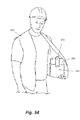
FIG. 34 illustrates a vest which can be used to the transport the case shown in FIG. 13.
FIG. 35 is a front view of a tablet case according to another embodiment of the invention.
FIG. 36 is a rear view of the case shown in FIG. 35.
FIG. 37 is a top view of the case shown in FIG. 35.
FIG. 38 is a side view of the case shown in FIG. 35.
FIG. 39 illustrates a controller or use with the case shown in FIG. 35.
Before any embodiments of the invention are explained in detail, it is to be understood that the invention is not limited in its application to the details of construction and the arrangement of components set forth in the following description or illustrated in the following drawings. The invention is capable of other embodiments and of being practiced or of being carried out in various ways.
DETAILED DESCRIPTION
FIGS. 1-12 illustrate a case 10 according to one embodiment of the invention. The case 10 is used with a tablet or tablet computer 11. A tablet is a personal computer, which receives input from a touch screen, rather than a physical keyboard or mouse. The case 10 includes a front portion or housing 15 and a rear portion or housing 20, and the front portion 15 is coupled to the rear portion 20 by a hinge 25. A user can operate the computer through an aperture 27 of the front portion 15.
Referring to FIGS. 2 and ,3 the front portion 15 of the case 10 includes a docking area 30 and speaker apertures 35. The docking area 30 is an area where a tablet is enclosed by the case 10. The speaker apertures 35 allow sound from the tablet's speaker (not shown) to exit from the case 10. With the case 10 in an open position, sound from the tablet speaker exits through the speaker apertures 35 after being channeled from a rear of the tablet toward a user by a sound channel 37 formed in the rear portion 20 of the case 10. Tablets often include speakers that are located in the rear of the tablet. Therefore, sound must be directed from the rear of the tablet out towards the user, or otherwise be muffled when the tablet is enclosed within the case 10. The sound channel 37 directs the sound from the rear of the tablet, and outputs the sound through the speaker apertures 35. In one embodiment the front portion 15 includes apertures to access buttons/switches of the tablet.
The hinge 25 allows the front portion 15 to open with respect to the rear portion 20, and thereby provide access to the docking area 30. Once the case 10 is open, a tablet may be placed in the docking area 30. When placed in the docking area 30, the tablet connects to a dock connector 40. The dock connector 40 electrically connects the tablet to electrical components of the case 10, and will be discussed in further detail below. Once the case 10 is closed (FIGS. 1 and 2), latches 45 further couple the front portion 15 to the rear portion 20, thereby securing the tablet within the docking area 30 of the case 10. In the illustrated embodiment, the case 10 includes three latches 45. Along with the hinge 25, the latches 45 couple the front portion 15 to the rear portion 20 on all four sides of the case 10. Coupling the front portion 15 to the rear portion 20 on all four sides of the case 10 fully secures the tablet within the docking area 30, as well as creates a seal between the front portion 15 and the rear portion 20. In another embodiment, the case 10 has a removable panel rather than a hinge 25. The removable panel opens and the tablet is slid into the docking area 30 of the case 10. In another embodiment, the case 10 includes a rubberized bezel rather than a hinge 25. The rubberized bezel stretches to allow the tablet to be placed in the docking area 30 of the case 10. Also shown in FIG. 3 is a fan 95, which is included in the rear portion 20 and is discussed in further detail below.
FIGS. 4-6 illustrates the rear portion 20 of the case 10. The rear portion 20 includes a controller 50 (FIG. 7), a battery receptacle 55, a handle 60, a USB port 65, an LED light array 70, and LED switch 75, a stylus holder 80, a camera aperture 85, a kickstand 90, the fan 95, air holes 100, and a fan switch 105.
As illustrated in FIG. 7, the controller 50 is electrically and/or communicatively connected to a variety of modules or components of the case 10. For example, the illustrated controller 50 is connected to the dock connector 40, battery receptacle 55, USB port 65, LED light array 70, LED switch 75, fan 95, and fan switch 105. The controller 50 includes combinations of hardware and software that are operable to, among other things, control the operation of components of the controller 50.
In some embodiments, the controller 50 includes a plurality of electrical and electronic components that provide power, operational control, and protection to the components and modules within the controller 50 and/or case 10. For example, the controller 50 includes, among other things, a processing unit 51 (e.g., a microprocessor, a microcontroller, or another suitable programmable device) and a memory unit 52. In some embodiments, the processing unit 51 includes, among other things, a control unit, an arithmetic logic unit (“ALU”), and a plurality of registers. The memory unit 52 includes, for example, a program storage area and a data storage area. The program storage area and the data storage area can include combinations of different types of memory, such as read-only memory (“ROM”), random access memory (“RAM”) (e.g., dynamic RAM [“DRAM”], synchronous DRAM [“SDRAM”], etc.), electrically erasable programmable read-only memory (“EEPROM”), flash memory, a hard disk, an SD card, or other suitable magnetic, optical, physical, or electronic memory devices. The processing unit 51 is connected to the memory 52 and executes software instructions that are capable of being stored in a RAM of the memory 52 (e.g., during execution), a ROM of the memory 52 (e.g., on a generally permanent basis), or another non-transitory computer readable medium such as another memory or a disc. Software included in the implementation of the case 10 can be stored in the memory 52 of the controller 50. The software includes, for example, firmware, one or more applications, program data, filters, rules, one or more program modules, and other executable instructions. The controller 50 is configured to retrieve from the memory 52 and execute, among other things, instructions related to the control processes and method described herein. In other constructions, the controller 50 includes additional, fewer, or different components.
The case 10 further includes a battery 110. The battery 110 is placed within the battery receptacle 55, and is locked into position. The battery 110 provides DC power to the controller 102. The tablet receives power from the battery 110 when connected to the dock connector 40, thereby extending a charge of the internal tablet battery. In some embodiments, the battery 110 is a rechargeable lithium-ion battery. In other embodiments, the battery 110 may have a chemistry other than lithium-ion such as, for example, nickel cadmium, nickel metal-hydride, etc. Additionally or alternatively, the battery 110 may be a non-rechargeable battery. In some embodiments, the battery 110 is a power tool battery pack including a pack housing containing one or more battery cells and latching mechanisms for selectively securing the battery 110 to the battery receptacle 55. The battery 110 has a nominal voltage (e.g., 12-volts, 18-volts, etc.) which is outputted to the controller 50. In the illustrated embodiment, the battery receptacle 55 is integrated into the case handle 60, which is an ergonomic bale style handle. The handle 60 enables a secure single hand hold on the case 10, allowing the user to operate the tablet with one hand while holding the tablet with the other.
The USB port 65 allows the user to connect the tablet to an external power source, personal computer, or other USB devices, while the tablet remains enclosed within the case 10. The USB port 65 is connected to the dock connector 40 via the main circuit. In one embodiment, the USB port 65 is a mini USB port, however, the USB port 65 can be any type or size of a Universal Serial Bus port.
The LED light array 70 provides a light source, which may be used as a camera flash for the tablet camera or as a flashlight. In the illustrated embodiment, the LED light array 70 includes multiple LED lights. In another embodiment, the LED light array 70 includes a single LED light or other light source. The LED switch 75 controls operation of the LED light array 70. In some embodiments, the LED switch 75 is an on/off switch, which either powers the LED light array 70 on or off. In another embodiment the LED switch 75 is a toggle switch, which toggles between different functions of the LED light array 70, such as on/off, a strobe function, or brightness of the LED light array 70. In the illustrated embodiment, the controller 50 receives an ON light signal from the LED switch 75. The controller 50 activates the LED light array 70 in response to receiving the ON light signal. In another embodiment, the LED switch 75 is connected in series between the controller 50 and the LED light array 70. In such an embodiment, when in the ON position, the LED switch 75 is operable to allow current to the LED light array 70, thus turning the LED light array 70 on. When in the OFF position, the LED switch 75 is operable to prevent current to the LED light array 70.
The stylus holder 80 holds a tablet stylus or similar writing utensil, which is used to assist navigating or provides more precision when using touch screen tablets. The camera aperture 85 allows a camera of the tablet to be used while the tablet is contained within the case 10. The camera aperture 85 may include a metal ring to accommodate after-market magnetic lenses, which may be used with the tablet camera.
FIG. 8 illustrates the kickstand 90 of the case in an extended position. The kickstand 90 is placed in the extended position when used to support the case 10 in a portrait orientation. Otherwise, the kickstand 90 is retracted into the case 10, as shown in FIGS. 4, 5, and 6. When retracted into the case 10, the kickstand 90 does not restrict access to the USB port 65. In one embodiment, the kickstand 90 uses a ball detent mechanism to lock the kickstand 90 in the extended and retracted positions.
Referring to FIGS. 3-4 and 9-10, the fan 95, air holes 100, air slits 110, 115, and air channels 120, 125 are used to keep the tablet at a desirable operating temperature. The fan 95 pulls cool air in through the air slit 110 using the air channel 120. The cool air is then channeled across the rear of the tablet, thereby cooling the tablet to an optimal operating temperature. The air exits through the air slit 115 via the air channel 125. Air holes 100 may be used as an additional air inlet or outlet, for example if either or both air slits 110, 115 become restricted. The seal created when the front portion 15 and rear portion 20 are latched closed allows the air to flow as described above, without air leakage occurring between the two portions 15, 20.
The fan switch 105 controls operation of the fan 95. In some embodiments, the fan switch 105 is an on/off switch, which either powers the fan 95 on or off. In another embodiment the fan switch 105 is a toggle switch, or knob, which controls the operating speed of the fan 95. In the illustrated embodiment, the controller 50 receives an ON fan signal from the fan switch 105. The controller 50 activates the fan 95 in response to receiving the ON fan signal. In another embodiment, the fan switch 105 is connected in series between the controller 50 and the fan 95. In such an embodiment, when in the ON position, the fan switch 105 is operable to allow current to the fan 95, thus turning the fan 95 on. When in the OFF position, the fan switch 105 is operable to prevent current to the fan 95.
FIGS. 10 and 11 illustrate the case 10 in a typing position. When in the typing position the case 10 is laid on the rear portion 20. When the battery 110 is placed within the battery receptacle 55, the battery 110 and handle 60 form a continuous support surface. The handle 60 and battery 110 prop up one end of the case 10, resulting in the case 10 resting at an angle between approximately 10 degrees and approximately 15 degrees.
FIG. 12 illustrates the case 10 in a landscape orientation. In this orientation, the handle 60 supports the case 10, rather than the kickstand 90. In one embodiment, the case 10 is at an angle between approximately 80° and approximately 85°.
In some embodiments, the handle 60 of the case 10 includes one or more buttons to control operation of the tablet, including for example, taking photos, controlling the volume, etc. The buttons communicate with the tablet via the dock connector 40.
FIGS. 13-29 illustrate a case 200 according to another embodiment of the invention, which is used to protect the tablet or tablet computer 11 from damage. The case 200 includes a front portion 205, a rear portion 210, and a sleeve 215. In one embodiment the front portion 205 and the rear portion 210 are composed of plastic, or a similar rigid material, while the sleeve 215 is composed of silicone, or a similar flexible material. In other embodiments, the front portion 205 and rear portion 210 are composed of wood, metal, or other known materials, and the sleeve 215 is composed of rubber or a similar elastic polymer.
FIGS. 16 and 17 illustrate the front portion 205 of the case 200. The front portion 205 includes a clear protective lens 220, a push-button aperture 225, a front-camera aperture 230, a tab 235, and a hook 240. The clear protective lens 220 protects the screen of the tablet 11 while allowing full use of the tablet touch screen. In the illustrated embodiment, the clear protective lens 220 is composed of polyurethane, or a similar material that allows full use of the tablet touch screen. The push-button aperture 225 allows the user to operate a push button of the tablet 11, and the front-camera aperture 230 allows a front camera of the tablet to be operated. The tab 235 and hook 240 are explained in greater detail in connection with enclosing a tablet 11 within the case 200.
FIGS. 18 and 19 illustrate the rear portion 210 of the case 200. The rear portion 210 includes a handle 245, a rear-camera aperture 250, an accessory-attachment point 255, speaker apertures 260, a stand 265, a latch 270, and a buckle 275. The handle 245 includes a strap 280 and a handle base 285. The strap 280 allows a user to hold the case 200 using one-hand. The handle base 285 allows rotation of the case 200 three-hundred and sixty degrees with respect to the handle 245. This allows the user to hold the case 200 using the strap 280, while the case 200 can pivot three-hundred and sixty degrees around the handle base 285.
The rear-camera aperture 250 allows a rear camera of the tablet 11 to be operated. The accessory-attachment point 255 allows attachment of various accessories to the case 200 (e.g., a stylus). In another embodiment discussed in further detail below, the accessory-attachment point 255 is used with a shoulder strap for hands-free carrying of the case 200. The speaker apertures 260 allow sound from a speaker of the tablet 11 to exit from the case 200.
As shown in FIGS. 20A-20C the stand 265 supports the case 200 in a portrait orientation. The stand 265′ is placed in an extended position when used to support the case 200 in a portrait orientation. Otherwise, the stand 265 is retracted into the case 200. Both positions of the stand 265 are shown in FIGS. 20A-20C. As shown in FIG. 20B, the stand 265 supports the case 200 in a portrait orientation at an approximately 60° angle. As shown in FIG. 20C, the stand 265 supports the case 200 in a portrait orientation at an approximately 30° angle. The stand 265 may also support the case 200 in a landscape orientation in a similar fashion by rotating the position of the handle base 285 approximately 90° from the position, in either direction, shown in FIG. 18. Although shown in FIG. 18 as retracted into the handle base 285, in other embodiments the stand 265 retracts into other areas of the rear portion 210 of the case 200.
FIGS. 21-23 illustrate the sleeve 215 of the case 200. The sleeve 215 includes a sleeve rear-camera aperture 290. The sleeve rear-camera aperture aligns with the rear-camera aperture 250 (FIG. 18) of the rear portion 210 of the case 200. The sleeve rear-camera aperture 290, along with the rear-camera aperture 250, allows the rear camera of the tablet 11 to be operated.
The sleeve 215 further includes a sleeve speaker aperture 295. The sleeve speaker aperture 295 aligns with the speaker apertures 260 (FIG. 18) of the rear portion 210 of the case 200. The sleeve speaker aperture 295, along with the speaker apertures 260, allow sound from a speaker of the tablet 11 to exit from the case 200.
The sleeve 215 further includes a volume-button boot 300. In some embodiments, the volume-button boot 300 is located on a side of the sleeve 215. The volume-button boot 300 allows the user to operate the volume controls of the tablet 11, while protecting the volume controls from the outside environment.
The sleeve 215 further includes a switch door 305. In some embodiments, the switch door 305 is located on the side of the sleeve 215. The switch door 305 has an open position and a closed position. When in the open position, the switch door 305 allows access to one or more switches of the tablet 11. When in the closed position, the switch door 305 prevents access to the switches and protects the switches from the outside environment.
The sleeve 215 further includes a headphone-jack door 310. In some embodiments, the headphone-jack door 310 is located on the top of the sleeve 215. The headphone-jack door 310 has an open position and a closed position. When in the open position, the headphone-jack door 310 allows access to a headphone jack of the tablet 11. When in the closed position, the headphone-jack door 310 prevents access to the headphone-jack and protects the head-phone jack from the outside environment.
The sleeve 215 further includes a button boot 315. In some embodiments, the button boot 315 is located on the top of the sleeve 215. The button boot 315 allows the user to operate a button, such as a power button or lock button, of the tablet 11, while protecting the button from the outside environment.
The sleeve 215 further includes a dock-connector door 320. In some embodiments, the dock-connector door 320 is located on the bottom of the sleeve 215. The dock-connector door 320 has an open position and a closed position. When in the open position, the dock-connector door 320 allows access to a port, such as a dock-connector, of the tablet 11. When in the closed position, the dock-connector door 320 prevents access to the port and protects the port from the outside environment.
The sleeve 215 further includes impact bumpers 325. The impact bumpers 325 protect the tablet 11 from impact, such as impact from a drop or a fall. The impact bumpers are thicker areas of the sleeve 215, which cover the corners of the tablet 11.
FIGS. 24-27 illustrate operation of enclosing the tablet 11 within the case 200. As illustrated in FIG. 24, the tablet 11 is first placed within the sleeve 215. Referring to FIG. 25, the sleeve 215 containing the tablet 11 is placed within the rear portion 210 of the case. Referring to FIGS. 26 and 27, the front portion 215 is then coupled to the rear portion 210, thereby enclosing the sleeve 215 within. The tab 235 of the front portion 15 couples to the latch 270 of the rear portion 210 in order to secure the two portions together. The buckle 275 of the rear portion 210 is then latched onto the hook 240 of the front portion 205 for further securement.
FIGS. 28 and 29 illustrate snaps 330 and snap apertures 335 to further secure the front portion 205 of the case 200 to the rear portion 210. In the illustrated embodiment, the snaps 330 are located on the side of the front portion 205 and the snap apertures 335 are located on the side of the rear portion 210. In other embodiments, the location of the snaps 330 snap apertures 335 are reversed.
FIGS. 30-33 illustrate the accessory-attachment point 255 in use with a shoulder strap 340 for hands-free carrying of the case 200. Referring to FIG. 30, the shoulder strap 340 is attached to the accessory-attachment point 255 via a carabiner 345, or similar attachment mechanism. The shoulder strap 340 further includes a shoulder pad 350 and an adjustable connector 355. The shoulder pad 350 adds padding to the shoulder strap 350 for additional comfort. The shoulder pad 350 can further include a non-slip surface, such as rubber, to secure the shoulder strap 340 on the user's shoulder. The adjustable connector 355 allows the shoulder strap 340 to be adjusted based on the height and/or preference of the user. As shown in FIG. 31, the shoulder strap 340 allows hands-free carrying of the case 200. As shown in FIGS. 32 and 33, another embodiment of the case 200 includes two or more accessory-attachment points 255′. In this embodiment, the shoulder strap 340′ is attached to the case 200 via the two attachment points 255′.
FIG. 34 illustrates a vest 360, which can be used with the case 200. The vest 360 includes a pocket 365 and a closure strap 370. The case 200 fits into the pocket 365 and is secured within the pocket 365 by the strap 370. In the illustrated embodiment, the strap 370 connects to the pocket 365 via snaps, Velcro, or other similar attachment devices, thereby securing the case 200 within the pocket 365. In another embodiment, the strap 370 connects to the accessory-attachment point 255, of the case 200, to secure the case 200 within the pocket 365.
FIGS. 35-39 illustrate a case 500 according to another embodiment invention. The case 500 is similar to the embodiment shown in FIGS. 13-29, and only new features of the case 500 will be described herein. The case 500 includes a battery receptacle 505, a light 510, a light switch 515, a fuel gauge 520, a fuel gauge switch 525, and fan vents 530.
The battery receptacle 505 is located on the handle base 285 of the case 500. The handle base 285 and the battery receptacle 505 are located in the rear of the case 500. The battery receptacle is operable to receive the battery 110. The battery receptacle 505, along with the strap 280, constitute a handle 507. The handle 507 allows the user to hold the case 500.
The light 510 is located on the battery receptacle 505. The light 510 provides a light source, which may be used as a camera flash for the tablet camera or as a flashlight. In the illustrated embodiment, the light 510 is a single LED (light-emitting diode) light. In another embodiment, the light 510 includes a plurality of LED lights or another light source. The light switch 515 is located on the battery receptacle 505 in proximity to the light 510. The light switch 515 controls operation of the light 510. In one embodiment, the light switch 515 is an on/off switch, which either powers the light 510 on or off. In another embodiment the light switch 515 is a toggle switch, which toggles between different functions of the light 510, such as on/off, a strobe function, or brightness of the light 510.
The fuel gauge 520 provides an indication of the charge of the battery 110. The fuel gauge 520 includes a display 535. The fuel gauge switch 525 controls activation of the display 535. In one embodiment, the display 535 comprises of multiple LEDs arranged to form a scale. A number of LEDs are illuminated when the battery 110 is charged, while one or no LEDs are illuminated when the battery 110 is not charged. In another embodiment, the display 535 includes one or more LEDs, one of which is green and one of which is red. When the battery 110 is charged the green LED is illuminated, when the battery 110 is not charged the red LED is illuminated. In another embodiment the display 535 comprises an LCD (liquid crystal display), or similar screen, which displays an indication of the charge of the battery 110.
The fan vents 530 are located on the handle base 285 of the case 500. The fan vents 530 are used in conjunction with a fan to keep the tablet 500 at a desirable operating temperature. The fan pulls in cool air through the fan vents 530 to cool the tablet 500.
When the battery 110 is placed within the battery receptacle 505, the battery 110 can further act as a stand to support the case 500 in a portrait orientation or a landscape orientation.
Referring to FIG. 39, a controller 550 for use with the case 500 is shown. The controller 550 has a similar construction as the controller 50, discussed above with respect to FIGS. 1-12. The controller 550 controls the operation of the case 500 and is electrically connected to the battery receptacle 505, the light 510, the light switch 515, the fuel gauge 520, the fuel gauge switch 525, and the fan.
Thus, the invention provides, among other things, a computer case for protecting a computer, such as a tablet computer. Various features and advantages of the invention are set forth in the following claims.

Claims (20)

What is claimed is:
1. A computer case for protecting a computer, the computer case comprising:
a front housing including a first aperture operable to allow a user to operate the computer; and
a rear housing pivotally coupled to the front housing, the rear housing including a latch for securing the computer between the front housing and the rear housing, a battery receptacle for receiving a battery, an electrical interface for electrical communication with the computer, an electrical input, a light powered by the battery, a fuel gauge having at least one fuel light, and a controller operable to
receive power from the battery,
provide power to the computer via the electrical interface,
provide power to the light,
determine a voltage of the battery,
display the voltage of the battery by providing power to the at least one fuel light of the fuel gauge,
receive an electrical signal from the electrical input, and
output the electrical signal to the computer via the electrical interface.
2. The computer case of claim 1, further comprising a handle.
3. The computer case of claim 2, wherein the battery receptacle is integrally formed with the handle.
4. The computer case of claim 1, wherein the handle is operable to support the case in a landscape orientation or a portrait orientation.
5. The computer case of claim 1, further comprising a fan supported by the rear housing and powered by the battery, the fan operable to regulate a temperature of the computer.
6. The computer case of claim 5, further comprising a fan switch operable to control power to the fan.
7. The computer case of claim 1, further comprising a light switch operable to control power to the light.
8. The computer case of claim 1, further comprising a sleeve for receiving the computer, wherein the sleeve is disposed in a cavity formed by the front and rear housings.
9. The computer case of claim 1, wherein the battery is a power tool battery.
10. A computer case for protecting a computer, the computer case comprising:
a front housing including a first aperture operable to allow a user to operate the computer;
a rear housing including a latch, a handle, a light powered by the battery, and a fuel gauge having at least one fuel light, the fuel gauge operable to display a voltage of the battery via the at least one fuel light, and
a sleeve including a plurality of bumpers, wherein the computer is placed within the sleeve and the sleeve is placed between the front and rear housing, and further wherein the latch secures the front housing and the rear housing in a closed position.
11. The computer case of claim 10, wherein the front housing and the rear housing are composed of plastic.
12. The computer case of claim 10, wherein the sleeve is composed of rubber.
13. The computer case of claim 10, further comprising a battery receptacle coupled to the rear housing, the battery receptacle configured for receiving a battery.
14. The computer case of claim 13, wherein the battery is a power tool battery.
15. The computer case of claim 13, wherein the rear housing further includes a fan operable to regulate the temperature of the computer, the fan powered by the battery.
16. The computer case of claim 15, further comprising a controller operable to control at least one of the light, the fuel gauge, and the fan.
17. The computer case of claim 13, wherein the battery receptacle and battery are operable to support the computer case in a portrait orientation.
18. The computer case of claim 10, wherein the bumpers are operable to protect the computer from impact.
19. A computer case for protecting a computer, the computer case comprising:
a front housing including a first aperture operable to allow a user to operate the computer; and
a rear housing pivotally coupled to the front housing, the rear housing including
a latch for securing the computer between the front housing and the rear housing,
a handle having a battery receptacle integrated into the handle, the battery receptacle configured to receive a battery,
an electrical interface for electrical communication with the computer, and
a controller operable to
receive power from the battery, and
provide power to the computer via the electrical interface.
20. The computer case of claim 19, wherein the battery, when received by the battery receptacle, is operable to support the computer case in at least one selected from the group consisting of a horizontal landscape and a vertical landscape.
US13/781,363 2012-02-29 2013-02-28 Tablet case Expired - Fee Related US9256258B2 (en)

Priority Applications (1)

Application Number Priority Date Filing Date Title
US13/781,363 US9256258B2 (en) 2012-02-29 2013-02-28 Tablet case

Applications Claiming Priority (3)

Application Number Priority Date Filing Date Title
US201261604958P 2012-02-29 2012-02-29
US201261650326P 2012-05-22 2012-05-22
US13/781,363 US9256258B2 (en) 2012-02-29 2013-02-28 Tablet case

Publications (2)

Publication Number Publication Date
US20130235521A1 US20130235521A1 (en) 2013-09-12
US9256258B2 true US9256258B2 (en) 2016-02-09

Family

ID=49113943

Family Applications (1)

Application Number Title Priority Date Filing Date
US13/781,363 Expired - Fee Related US9256258B2 (en) 2012-02-29 2013-02-28 Tablet case

Country Status (1)

Country Link
US (1) US9256258B2 (en)

Cited By (4)

* Cited by examiner, † Cited by third party
Publication number Priority date Publication date Assignee Title
USD800835S1 (en) 2017-05-05 2017-10-24 Robert Ballard Notebook holder
US10185358B1 (en) 2018-04-07 2019-01-22 Andrew Padua Bataller Electronic tablet protective carrying case and display stand
US20200177979A1 (en) * 2018-12-04 2020-06-04 Samsung Electronics Co., Ltd. Electronic device including speaker module
USD997944S1 (en) * 2021-08-05 2023-09-05 Cor Sanctum, LLC Anti-eavesdropping device

Families Citing this family (27)

* Cited by examiner, † Cited by third party
Publication number Priority date Publication date Assignee Title
US8964364B2 (en) * 2012-11-23 2015-02-24 Blackberry Limited Carrying case for controlling a mobile device
US9797542B2 (en) * 2013-03-15 2017-10-24 Lilitab LLC Latch and bezel system for device enclosure
US9075570B2 (en) * 2013-07-30 2015-07-07 Luhui Yuan Protective case with heat dissipation structure for electronic products
US9600028B2 (en) 2013-08-19 2017-03-21 Mildef, Inc. Enclosures for protecting devices and methods of manufacturing enclosures for protecting devices
US9400526B2 (en) * 2013-09-09 2016-07-26 Apple Inc. Bumper for a computing device and related assembly and method
US20150116286A1 (en) * 2013-10-30 2015-04-30 Lenovo (Singapore) Pte. Ltd. Tag and stabilizer for stylus attachment
US9419670B2 (en) * 2014-01-07 2016-08-16 Incipio, Llc Protective case for mobile device with integrated latch
US20200313713A1 (en) * 2014-01-07 2020-10-01 Incipio, Llc Protective case for mobile device with integrated latch
EP3129848A4 (en) 2014-04-09 2017-04-19 Microsoft Technology Licensing, LLC Hinged cover for computing device
EP3129846A4 (en) * 2014-04-10 2017-05-03 Microsoft Technology Licensing, LLC Collapsible shell cover for computing device
EP3129847A4 (en) 2014-04-10 2017-04-19 Microsoft Technology Licensing, LLC Slider cover for computing device
CN105302232A (en) 2014-06-04 2016-02-03 振桦电子股份有限公司 Tablet computer with detachable handle
CN106662891B (en) 2014-10-30 2019-10-11 微软技术许可有限责任公司 Multi-configuration input equipment
US10088865B1 (en) * 2014-11-06 2018-10-02 Amazon Technologies, Inc. Modular computing system
US11836020B2 (en) * 2014-11-11 2023-12-05 Darren Saravis Temperature regulating mount
US10877529B2 (en) 2014-11-11 2020-12-29 Darren Saravis Temperature regulating mount
US9836101B1 (en) * 2014-11-11 2017-12-05 Darren Saravis Cooling mount
US11262816B2 (en) 2014-11-11 2022-03-01 Darren Saravis Temperature regulating mount with magnetic power mount
US9519314B2 (en) * 2015-02-11 2016-12-13 IDS Global, Inc. Intrinsically safe case for a tablet computer
DE102015206571B3 (en) * 2015-04-13 2016-08-04 Kuka Roboter Gmbh Robotic hand-held device with an adapter device for a mobile terminal
US9829919B2 (en) * 2015-09-11 2017-11-28 Logitech Europe S.A. Protective cover for an input device
US10261568B2 (en) 2015-09-16 2019-04-16 Microsoft Technology Licensing, Llc Enhancing user experience relative to peripheral devices
US9912668B2 (en) 2015-09-16 2018-03-06 Microsoft Technology Licensing, Llc Enhancing user experience relative to peripheral devices
US9746881B2 (en) * 2016-01-14 2017-08-29 Phillip Q. Owens, JR. Apparatus for port expansion
WO2018222720A1 (en) * 2017-05-30 2018-12-06 Darren Saravis Temperature regulating mount
US10831248B2 (en) * 2018-05-09 2020-11-10 Adesa, Inc. Mobile device temperature-regulating case
USD983777S1 (en) * 2022-04-08 2023-04-18 Qian Ren Ng Phone case

Citations (54)

* Cited by examiner, † Cited by third party
Publication number Priority date Publication date Assignee Title
US3997819A (en) 1974-09-09 1976-12-14 Siemens Aktiengesellschaft Housing for electrical communications and measuring devices
DE3318581A1 (en) 1983-05-20 1984-11-22 Siemens AG, 1000 Berlin und 8000 München Method for sealing an electrical component, especially a relay, and a component which is sealed in accordance with this method
US4768230A (en) 1985-04-17 1988-08-30 Preh Elektrofeinmechanische Werke Jakob Preh Nachf. Gmbh & Co. Housing for a hand-held remote control transmitter
US4997103A (en) 1989-06-12 1991-03-05 Grid Systems Corporation Sliding door
US5105335A (en) 1988-04-28 1992-04-14 Kabushiki Kaisha Toshiba Hard case for housing and carrying electronic devices
DE4036994A1 (en) 1990-11-20 1992-05-21 Divetronic Ag Display in form of electrical-electronic instrument - has setting gel filling part of housing contg. electrical parts, and separate housing part for display LCD
US5146390A (en) 1991-03-08 1992-09-08 John Fluke Mfg. Co., Inc. Lcd support bracket
US5191544A (en) 1990-06-15 1993-03-02 International Business Machines Corp. Personal computer enclosure with shielding
US5239446A (en) 1991-05-24 1993-08-24 Matsushita Electric Industrial Co., Ltd. Watertight casing for electronic apparatus and assembling method therefor
US5327322A (en) 1993-03-30 1994-07-05 Ma Hsi Kuang Built-up pen base computer
US5329422A (en) 1990-11-30 1994-07-12 Kabushiki Kaisha Toshiba Portable electronic apparatus having optional components in a shielded recess for function expansion
US5331506A (en) 1991-10-11 1994-07-19 Kabushiki Kaisha Toshiba Electronic apparatus wherein components are detachably arranged in a housing having a recess with a sliding and clamping cover
US5360108A (en) 1993-08-24 1994-11-01 Sedi S.R.L. Electronic device shock absorber
US5373458A (en) 1993-06-30 1994-12-13 Intermec Corporation Enclosure for a hand-held computer
US5400213A (en) 1992-01-10 1995-03-21 Kabushiki Kaisha Toshiba Electronic device having detachable keyboard clamped by a rotatable display when closed over the keyboard
US5568358A (en) 1994-11-14 1996-10-22 Harris Corporation Multi-attitude display lid positioning arrangement for craftsperson's portable signal processing and communications unit
US5583742A (en) * 1993-12-15 1996-12-10 Alps Electric Co., Ltd. Computer with protective cover having outwardly projecting cushioning portions
US5586002A (en) 1992-06-24 1996-12-17 John Notarianni Protective case and interface housing containing computer devices and the like
US5796576A (en) 1995-10-04 1998-08-18 Samsung Electronics Co., Ltd. Notebook computer having a hinge device enabling a display unit to be separable from a main body
US5812188A (en) 1996-07-12 1998-09-22 Adair; Edwin L. Sterile encapsulated endoscopic video monitor
US5905632A (en) 1995-06-20 1999-05-18 Kobushiki Kaisha Toshiba Portable electronic apparatus having a battery pack receptacle
US5940153A (en) 1998-04-03 1999-08-17 Motorola, Inc. Display assembly having LCD and seal captured between interlocking lens cover and lightpipe
FR2777758A1 (en) 1998-04-27 1999-10-29 Christian Dollet Protective cover and carrier for a pocket computer.
USD419297S (en) 1999-02-23 2000-01-25 Curtis Richardson Water-tight container
WO2000004437A1 (en) 1998-07-17 2000-01-27 Therefore Limited Flexible cover for screen of an electronic device
US20010029588A1 (en) * 1998-02-02 2001-10-11 Akiyoshi Nakamura Portable information processing apparatus
US6317313B1 (en) * 1999-11-09 2001-11-13 Interlogix, Inc. Case and cover for an electronic device
US6354461B1 (en) 1999-03-26 2002-03-12 General Instrument Corporation Enclosure having a hinge member biased by a hand-operable latch
US6646864B2 (en) 2001-11-19 2003-11-11 Otter Products, Llc Protective case for touch screen device
US7023692B2 (en) 1998-06-19 2006-04-04 4P S.R.L. Multifunctional electronic palmtop computer
US20060104021A1 (en) * 2004-11-12 2006-05-18 Hon Hai Precision Industry Co., Ltd. PDA carrying device
US20060279924A1 (en) 2001-11-19 2006-12-14 Otter Products, Llc Protective enclosure for personal digital assistant case having integrated back lighted keyboard
US7158376B2 (en) 2001-11-19 2007-01-02 Otter Products, Llc Protective enclosure for an interactive flat-panel controlled device
US7180735B2 (en) 2001-11-19 2007-02-20 Otter Products, Llc Protective enclosure and watertight adapter for an interactive flat-panel controlled device
US7230823B2 (en) 2003-08-20 2007-06-12 Otter Products, Llc Protective membrane for touch screen device
US20070297149A1 (en) 2001-11-19 2007-12-27 Otter Products, Llc Modular accessory for protective case enclosing touch screen device
US7449650B2 (en) 2006-07-19 2008-11-11 Otter Products, Llc Multi-directional activation button
US20090009945A1 (en) * 2001-11-19 2009-01-08 Jamie Lee Johnson Protective enclosure for touch screen device
US7609512B2 (en) 2001-11-19 2009-10-27 Otter Products, Llc Protective enclosure for electronic device
US20100147737A1 (en) 2009-08-21 2010-06-17 Otter Products, Llc Protective cushion cover for an electronic device
US20100270188A1 (en) * 2009-02-09 2010-10-28 Leslie Chan Dotson Computer carring, cooling and support device
US7889489B2 (en) 2001-11-19 2011-02-15 Otter Products, Llc Detachable pod assembly for protective case
US20110073608A1 (en) 2009-09-30 2011-03-31 Otter Products, Llc Case
US7933122B2 (en) 2007-06-06 2011-04-26 Otter Products, Llc Protective enclosure for a computer
US20110159324A1 (en) * 2008-01-18 2011-06-30 Mophie, Inc. Battery pack, holster, and extendible processing and interface platform for mobile devices
US20110228458A1 (en) 2010-03-17 2011-09-22 Otter Products, Llc Multi-material protective case for sliding/articulating/rotating handheld electronic devices
US20110226545A1 (en) 2009-11-19 2011-09-22 Otter Products, Llc Acoustic isolation mechanism
US20110228459A1 (en) 2010-03-17 2011-09-22 Otter Products, Llc Energy deflection case
US20110259788A1 (en) * 2010-04-22 2011-10-27 Atoz Design Labs Co., Limited Tablet pc cover with stowable input device
US20120018323A1 (en) 2010-07-20 2012-01-26 Otter Products, Llc Flash Isolation for Device Covers
US20120074005A1 (en) 2010-09-24 2012-03-29 Otter Products, Llc Edge retention for flexible cover
US8191706B1 (en) * 2011-03-29 2012-06-05 Mitac International Corp. Protective casing adapted for different electronic devices
US20120262618A1 (en) * 2011-04-14 2012-10-18 Amphibian Labs Llc Waterproof case for hand held computing device
US8503170B1 (en) * 2012-03-01 2013-08-06 First International Computer, Inc. Waterproof and shockproof cover for a PAD computer

Patent Citations (62)

* Cited by examiner, † Cited by third party
Publication number Priority date Publication date Assignee Title
US3997819A (en) 1974-09-09 1976-12-14 Siemens Aktiengesellschaft Housing for electrical communications and measuring devices
DE3318581A1 (en) 1983-05-20 1984-11-22 Siemens AG, 1000 Berlin und 8000 München Method for sealing an electrical component, especially a relay, and a component which is sealed in accordance with this method
US4768230A (en) 1985-04-17 1988-08-30 Preh Elektrofeinmechanische Werke Jakob Preh Nachf. Gmbh & Co. Housing for a hand-held remote control transmitter
US5105335A (en) 1988-04-28 1992-04-14 Kabushiki Kaisha Toshiba Hard case for housing and carrying electronic devices
US4997103A (en) 1989-06-12 1991-03-05 Grid Systems Corporation Sliding door
US5191544A (en) 1990-06-15 1993-03-02 International Business Machines Corp. Personal computer enclosure with shielding
DE4036994A1 (en) 1990-11-20 1992-05-21 Divetronic Ag Display in form of electrical-electronic instrument - has setting gel filling part of housing contg. electrical parts, and separate housing part for display LCD
US5329422A (en) 1990-11-30 1994-07-12 Kabushiki Kaisha Toshiba Portable electronic apparatus having optional components in a shielded recess for function expansion
US5146390A (en) 1991-03-08 1992-09-08 John Fluke Mfg. Co., Inc. Lcd support bracket
US5239446A (en) 1991-05-24 1993-08-24 Matsushita Electric Industrial Co., Ltd. Watertight casing for electronic apparatus and assembling method therefor
US5331506A (en) 1991-10-11 1994-07-19 Kabushiki Kaisha Toshiba Electronic apparatus wherein components are detachably arranged in a housing having a recess with a sliding and clamping cover
US5400213A (en) 1992-01-10 1995-03-21 Kabushiki Kaisha Toshiba Electronic device having detachable keyboard clamped by a rotatable display when closed over the keyboard
US5586002A (en) 1992-06-24 1996-12-17 John Notarianni Protective case and interface housing containing computer devices and the like
US5327322A (en) 1993-03-30 1994-07-05 Ma Hsi Kuang Built-up pen base computer
US5373458A (en) 1993-06-30 1994-12-13 Intermec Corporation Enclosure for a hand-held computer
US5360108A (en) 1993-08-24 1994-11-01 Sedi S.R.L. Electronic device shock absorber
US5583742A (en) * 1993-12-15 1996-12-10 Alps Electric Co., Ltd. Computer with protective cover having outwardly projecting cushioning portions
US5568358A (en) 1994-11-14 1996-10-22 Harris Corporation Multi-attitude display lid positioning arrangement for craftsperson's portable signal processing and communications unit
US5905632A (en) 1995-06-20 1999-05-18 Kobushiki Kaisha Toshiba Portable electronic apparatus having a battery pack receptacle
US5796576A (en) 1995-10-04 1998-08-18 Samsung Electronics Co., Ltd. Notebook computer having a hinge device enabling a display unit to be separable from a main body
US5812188A (en) 1996-07-12 1998-09-22 Adair; Edwin L. Sterile encapsulated endoscopic video monitor
US20010029588A1 (en) * 1998-02-02 2001-10-11 Akiyoshi Nakamura Portable information processing apparatus
US5940153A (en) 1998-04-03 1999-08-17 Motorola, Inc. Display assembly having LCD and seal captured between interlocking lens cover and lightpipe
FR2777758A1 (en) 1998-04-27 1999-10-29 Christian Dollet Protective cover and carrier for a pocket computer.
US7023692B2 (en) 1998-06-19 2006-04-04 4P S.R.L. Multifunctional electronic palmtop computer
WO2000004437A1 (en) 1998-07-17 2000-01-27 Therefore Limited Flexible cover for screen of an electronic device
USD419297S (en) 1999-02-23 2000-01-25 Curtis Richardson Water-tight container
US6354461B1 (en) 1999-03-26 2002-03-12 General Instrument Corporation Enclosure having a hinge member biased by a hand-operable latch
US6317313B1 (en) * 1999-11-09 2001-11-13 Interlogix, Inc. Case and cover for an electronic device
US6995976B2 (en) 2001-11-19 2006-02-07 Otter Products, Llc Protective membrane for touch screen device
US20070297149A1 (en) 2001-11-19 2007-12-27 Otter Products, Llc Modular accessory for protective case enclosing touch screen device
US7907394B2 (en) 2001-11-19 2011-03-15 Otter Products, Llc Protective enclosure for touch screen device
US20060279924A1 (en) 2001-11-19 2006-12-14 Otter Products, Llc Protective enclosure for personal digital assistant case having integrated back lighted keyboard
US7158376B2 (en) 2001-11-19 2007-01-02 Otter Products, Llc Protective enclosure for an interactive flat-panel controlled device
US7180735B2 (en) 2001-11-19 2007-02-20 Otter Products, Llc Protective enclosure and watertight adapter for an interactive flat-panel controlled device
US7889489B2 (en) 2001-11-19 2011-02-15 Otter Products, Llc Detachable pod assembly for protective case
US20070139873A1 (en) 2001-11-19 2007-06-21 Otter Products, Llc Protective enclosure and watertight adapter for an interactive flat-panel controlled device
US7312984B2 (en) 2001-11-19 2007-12-25 Otter Products, Llc Protective enclosure and watertight adapter for an interactive flat-panel controlled device
US6646864B2 (en) 2001-11-19 2003-11-11 Otter Products, Llc Protective case for touch screen device
US7688580B2 (en) 2001-11-19 2010-03-30 Otter Products, Llc Modular accessory for protective case enclosing touch screen device
US20090009945A1 (en) * 2001-11-19 2009-01-08 Jamie Lee Johnson Protective enclosure for touch screen device
US7609512B2 (en) 2001-11-19 2009-10-27 Otter Products, Llc Protective enclosure for electronic device
US20100008028A1 (en) 2001-11-19 2010-01-14 Otter Products, Llc Protective enclosure for electronic device
US7663879B2 (en) 2001-11-19 2010-02-16 Otter Products, Llc Protective enclosure for personal digital assistant case having integrated back lighted keyboard
US7230823B2 (en) 2003-08-20 2007-06-12 Otter Products, Llc Protective membrane for touch screen device
US20060104021A1 (en) * 2004-11-12 2006-05-18 Hon Hai Precision Industry Co., Ltd. PDA carrying device
US7449650B2 (en) 2006-07-19 2008-11-11 Otter Products, Llc Multi-directional activation button
US7933122B2 (en) 2007-06-06 2011-04-26 Otter Products, Llc Protective enclosure for a computer
US20110159324A1 (en) * 2008-01-18 2011-06-30 Mophie, Inc. Battery pack, holster, and extendible processing and interface platform for mobile devices
US20100270188A1 (en) * 2009-02-09 2010-10-28 Leslie Chan Dotson Computer carring, cooling and support device
US20100147737A1 (en) 2009-08-21 2010-06-17 Otter Products, Llc Protective cushion cover for an electronic device
US20110073608A1 (en) 2009-09-30 2011-03-31 Otter Products, Llc Case
US20110226545A1 (en) 2009-11-19 2011-09-22 Otter Products, Llc Acoustic isolation mechanism
US20110228458A1 (en) 2010-03-17 2011-09-22 Otter Products, Llc Multi-material protective case for sliding/articulating/rotating handheld electronic devices
US20110228459A1 (en) 2010-03-17 2011-09-22 Otter Products, Llc Energy deflection case
US9025317B2 (en) * 2010-03-17 2015-05-05 Otter Products, Llc Multi-material protective case for sliding/articulating/rotating handheld electronic devices
US20110259788A1 (en) * 2010-04-22 2011-10-27 Atoz Design Labs Co., Limited Tablet pc cover with stowable input device
US20120018323A1 (en) 2010-07-20 2012-01-26 Otter Products, Llc Flash Isolation for Device Covers
US20120074005A1 (en) 2010-09-24 2012-03-29 Otter Products, Llc Edge retention for flexible cover
US8191706B1 (en) * 2011-03-29 2012-06-05 Mitac International Corp. Protective casing adapted for different electronic devices
US20120262618A1 (en) * 2011-04-14 2012-10-18 Amphibian Labs Llc Waterproof case for hand held computing device
US8503170B1 (en) * 2012-03-01 2013-08-06 First International Computer, Inc. Waterproof and shockproof cover for a PAD computer

Cited By (5)

* Cited by examiner, † Cited by third party
Publication number Priority date Publication date Assignee Title
USD800835S1 (en) 2017-05-05 2017-10-24 Robert Ballard Notebook holder
US10185358B1 (en) 2018-04-07 2019-01-22 Andrew Padua Bataller Electronic tablet protective carrying case and display stand
US20200177979A1 (en) * 2018-12-04 2020-06-04 Samsung Electronics Co., Ltd. Electronic device including speaker module
US11012766B2 (en) * 2018-12-04 2021-05-18 Samsung Electronics Co., Ltd. Electronic device including speaker module
USD997944S1 (en) * 2021-08-05 2023-09-05 Cor Sanctum, LLC Anti-eavesdropping device

Also Published As

Publication number Publication date
US20130235521A1 (en) 2013-09-12

Similar Documents

Publication Publication Date Title
US9256258B2 (en) Tablet case
US8708140B2 (en) Mobile device enclosure system
US8997983B2 (en) Combination protective case and stand for a tablet device and keyboard
US8064193B2 (en) Laptop accessory holder
US10877529B2 (en) Temperature regulating mount
US11392185B2 (en) Temperature regulating mount
US9013863B2 (en) Protective sheath
US20070201201A1 (en) Bag computer
US20130203473A1 (en) Cellular Phone Case having a Keyboard Input
US20130106353A1 (en) Mobile communication device housing
US20050174727A1 (en) Protective enclosure and watertight adapter for an interactive flat-panel controlled device
US7505252B2 (en) Notebook computer
US20120088558A1 (en) Phone case
US20140224676A1 (en) Low profile protective cover configurable as a stand with integrated battery
US20120147536A1 (en) Casing Device for Portable Electronic Device
US20160277052A1 (en) Modular Portable Power Device
US20240061479A1 (en) Temperature regulating mount
US6958905B2 (en) Mobile body-supported computer with battery
KR200465854Y1 (en) A bag whit tablet personal computer storage function
US20120247983A1 (en) Tablet bay and bag incorporating the same
US11360516B2 (en) Portable device for processing, transmitting, and receiving information, sound, and video
AU2018277826B2 (en) Temperature regulating mount
JPH0643965A (en) Information processor
KR101341368B1 (en) A case for tablet personal computer
CN213957944U (en) Protective sleeve for tablet personal computer

Legal Events

Date Code Title Description
AS Assignment

Owner name: MILWAUKEE ELECTRIC TOOL CORPORATION, WISCONSIN

Free format text: ASSIGNMENT OF ASSIGNORS INTEREST;ASSIGNORS:BURCH, WADE F.;CROWE, JASON R.;HYMA, STEVEN W.;AND OTHERS;REEL/FRAME:029932/0901

Effective date: 20130301

STCF Information on status: patent grant

Free format text: PATENTED CASE

MAFP Maintenance fee payment

Free format text: PAYMENT OF MAINTENANCE FEE, 4TH YEAR, LARGE ENTITY (ORIGINAL EVENT CODE: M1551); ENTITY STATUS OF PATENT OWNER: LARGE ENTITY

Year of fee payment: 4

FEPP Fee payment procedure

Free format text: MAINTENANCE FEE REMINDER MAILED (ORIGINAL EVENT CODE: REM.); ENTITY STATUS OF PATENT OWNER: LARGE ENTITY

LAPS Lapse for failure to pay maintenance fees

Free format text: PATENT EXPIRED FOR FAILURE TO PAY MAINTENANCE FEES (ORIGINAL EVENT CODE: EXP.); ENTITY STATUS OF PATENT OWNER: LARGE ENTITY

STCH Information on status: patent discontinuation

Free format text: PATENT EXPIRED DUE TO NONPAYMENT OF MAINTENANCE FEES UNDER 37 CFR 1.362