US9261810B2 - Marking material delivery apparatus having multiple charge blades - Google Patents
Marking material delivery apparatus having multiple charge blades Download PDFInfo
- Publication number
- US9261810B2 US9261810B2 US13/963,018 US201313963018A US9261810B2 US 9261810 B2 US9261810 B2 US 9261810B2 US 201313963018 A US201313963018 A US 201313963018A US 9261810 B2 US9261810 B2 US 9261810B2
- Authority
- US
- United States
- Prior art keywords
- marking material
- charge
- blade
- charge blade
- feeder
- Prior art date
- Legal status (The legal status is an assumption and is not a legal conclusion. Google has not performed a legal analysis and makes no representation as to the accuracy of the status listed.)
- Expired - Fee Related, expires
Links
- 239000000463 material Substances 0.000 title claims description 112
- 238000011161 development Methods 0.000 claims abstract description 86
- 108091008695 photoreceptors Proteins 0.000 claims abstract description 28
- 238000012546 transfer Methods 0.000 claims abstract description 23
- 238000000034 method Methods 0.000 description 12
- 239000002245 particle Substances 0.000 description 7
- 238000010586 diagram Methods 0.000 description 4
- 230000006870 function Effects 0.000 description 4
- 238000003860 storage Methods 0.000 description 4
- 238000013461 design Methods 0.000 description 3
- 230000008569 process Effects 0.000 description 3
- 230000015654 memory Effects 0.000 description 2
- 230000003287 optical effect Effects 0.000 description 2
- 238000012545 processing Methods 0.000 description 2
- 239000000758 substrate Substances 0.000 description 2
- 229910000906 Bronze Inorganic materials 0.000 description 1
- RYGMFSIKBFXOCR-UHFFFAOYSA-N Copper Chemical compound [Cu] RYGMFSIKBFXOCR-UHFFFAOYSA-N 0.000 description 1
- 229910000831 Steel Inorganic materials 0.000 description 1
- 239000000956 alloy Substances 0.000 description 1
- 229910045601 alloy Inorganic materials 0.000 description 1
- 239000010974 bronze Substances 0.000 description 1
- 239000003990 capacitor Substances 0.000 description 1
- 239000004020 conductor Substances 0.000 description 1
- 229910052802 copper Inorganic materials 0.000 description 1
- 239000010949 copper Substances 0.000 description 1
- KUNSUQLRTQLHQQ-UHFFFAOYSA-N copper tin Chemical compound [Cu].[Sn] KUNSUQLRTQLHQQ-UHFFFAOYSA-N 0.000 description 1
- 238000009826 distribution Methods 0.000 description 1
- -1 etc.) Substances 0.000 description 1
- 238000001125 extrusion Methods 0.000 description 1
- 230000005484 gravity Effects 0.000 description 1
- 238000003384 imaging method Methods 0.000 description 1
- 229910052751 metal Inorganic materials 0.000 description 1
- 239000002184 metal Substances 0.000 description 1
- 238000003801 milling Methods 0.000 description 1
- 238000012986 modification Methods 0.000 description 1
- 230000004048 modification Effects 0.000 description 1
- 230000002093 peripheral effect Effects 0.000 description 1
- 230000000704 physical effect Effects 0.000 description 1
- 229920000642 polymer Polymers 0.000 description 1
- 239000000843 powder Substances 0.000 description 1
- 238000004080 punching Methods 0.000 description 1
- 238000010926 purge Methods 0.000 description 1
- 238000004064 recycling Methods 0.000 description 1
- 239000007787 solid Substances 0.000 description 1
- 239000010959 steel Substances 0.000 description 1
Images


Classifications
-
- G—PHYSICS
- G03—PHOTOGRAPHY; CINEMATOGRAPHY; ANALOGOUS TECHNIQUES USING WAVES OTHER THAN OPTICAL WAVES; ELECTROGRAPHY; HOLOGRAPHY
- G03G—ELECTROGRAPHY; ELECTROPHOTOGRAPHY; MAGNETOGRAPHY
- G03G15/00—Apparatus for electrographic processes using a charge pattern
- G03G15/06—Apparatus for electrographic processes using a charge pattern for developing
- G03G15/08—Apparatus for electrographic processes using a charge pattern for developing using a solid developer, e.g. powder developer
- G03G15/0806—Apparatus for electrographic processes using a charge pattern for developing using a solid developer, e.g. powder developer on a donor element, e.g. belt, roller
- G03G15/0808—Apparatus for electrographic processes using a charge pattern for developing using a solid developer, e.g. powder developer on a donor element, e.g. belt, roller characterised by the developer supplying means, e.g. structure of developer supply roller
-
- G—PHYSICS
- G03—PHOTOGRAPHY; CINEMATOGRAPHY; ANALOGOUS TECHNIQUES USING WAVES OTHER THAN OPTICAL WAVES; ELECTROGRAPHY; HOLOGRAPHY
- G03G—ELECTROGRAPHY; ELECTROPHOTOGRAPHY; MAGNETOGRAPHY
- G03G15/00—Apparatus for electrographic processes using a charge pattern
- G03G15/06—Apparatus for electrographic processes using a charge pattern for developing
- G03G15/065—Arrangements for controlling the potential of the developing electrode
Definitions
- Systems and methods herein generally relate to printing devices, and more particularly to charge blades within electrostatic printing devices.
- Electrostatic printing devices deliver a controlled amount of charged marking material (e.g., toner) to a photoreceptor (or other element capable of maintaining a latent image charge) using what is sometimes referred to as a development roll.
- the marking material is transferred from the development roll to the photoreceptor, and then from the photoreceptor to a sheet of media to perform printing on the sheet.
- the marking material is usually in the form of a powder, such as toner particles.
- a blade is used to scrape excess amounts of marking material off the development roll.
- the blade can provide a charge to the marking material particles and, therefore, the blade is sometimes referred to as a “charge blade.”
- An exemplary printing apparatus herein includes a sheet feeder and a photoreceptor adjacent the sheet feeder.
- the photoreceptor receives print media from the sheet feeder, and the photoreceptor transfers toner to the print media.
- a development roll is adjacent the photoreceptor.
- the development roll supplies a metered amount of charged toner to the photoreceptor.
- a supply roll is adjacent the development roll. The supply roll supplies toner to the development roll.
- multiple charge blades e.g., first, second, third, etc., charge blades
- a charge generator can be electrically connected to the charge blade, supply roll, and development roll.
- the development roll has an outer surface moving in a first direction.
- the first charge blade is positioned before the second charge blade in the first direction. Therefore, the moving outer surface of the development roll contacts the first charge blade before contacting the second charge blade (when moving in the first direction).
- the contact areas of all such charge blades are positioned in an arc, such that all of the contact areas of the charge blades simultaneously touch the curved outer surface of the development roll.
- the first charge blade produces a first amount of charge in the toner on the development roll
- the second charge blade increases the charge within the toner on the development roll (e.g., to a second amount of charge that is larger than the first amount of charge).
- the first charge blade applies the most pressure (force) of all the charge blades to control the amount of toner positioned on the development roll and the additional charge blades do not affect the amount of toner metered by the first, higher force charge blade.
- various print devices herein include a media feeder (one example of which is a sheet feeder); and a transfer device (one example of which is a photoreceptor) adjacent the media feeder.
- the transfer device receives print media from the media feeder, and the transfer device transfers marking material (one example of which is a toner) to the print media.
- a marking material feeder (one example of which is a development roll) is adjacent the transfer device.
- the marking material feeder supplies the marking material to the transfer device.
- a supply device (one example of which is a supply roll) is adjacent the marking material feeder. The supply device supplies the marking material to the marking material feeder.
- a charge generator can be electrically connected to the charge blade, supply roll, and marking material feeder.
- the marking material feeder has an outer surface moving in a first direction.
- the first charge blade is positioned before the second charge blade in the first direction. Therefore, the moving outer surface of the marking material feeder contacts the first charge blade before contacting the second charge blade (when moving in the first direction).
- the contact areas of all such charge blades are positioned in an arc, such that all of the contact areas of the charge blades simultaneously touch the curved outer surface of the marking material feeder.
- the first charge blade produces a first amount of charge in the toner on the marking material feeder
- the second charge blade increases the charge within the toner on the marking material feeder (e.g., to a second amount of charge that is larger than the first amount of charge).
- the first charge blade applies the most pressure of all the charge blades to control the amount of toner positioned on the marking material feeder, and the additional charge blades do not affect the amount of toner metered by the first, higher force charge blade.
- FIG. 1 is a cross-sectional schematic diagram illustrating devices herein
- FIG. 2 is a cross-sectional schematic diagram illustrating devices herein;
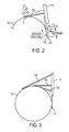
- FIG. 3 is a cross-sectional schematic diagram illustrating devices herein.
- FIG. 4 is a cross-sectional schematic diagram illustrating devices herein.
- a charge blade is used to remove excess amounts of marking material from the development roll and provide a charge to the marking material particles, thereby “metering charged particles” on the development roll.
- the devices described herein include multiple charge blades (applying different force levels against the development roll) to provide precise metering and charge control of marking material particles on a development roll.
- the physical structures described herein allow many different types of marking materials to be used in printing devices that require highly controlled charge and metering levels (and would otherwise require specialized marking materials). Therefore, in one example, the physical structures described herein allow a wider variety of marking materials to be used in devices that require a specific type of marking material, allowing less-polluting, lower-cost marking materials to be used in place of more expensive, more rare marking materials. This promotes more recycling of printing cartridges by a wider range of manufacturers, increasing competition, reducing consumer prices, and helping the environment.
- FIG. 1 illustrates a cross-section of a non-magnetic development system 80 - 83 .
- a printing device can include a single development system, and others (such as the one illustrated in FIG. 4 , discussed below) can include multiple development systems 80 - 83 . Therefore, FIG. 1 is intended to illustrate a stand-alone development device and/or a development device used in combination with other development devices.
- toner (T) is maintained in the cartridge sump 141 .
- a paddle 115 that rotates as shown by arrow E, is used to load a supply roller 113 with toner T by moving toner particles to the supply roll area in a direction shown by arrow 144 .
- the supply roller 113 rotates to transfer the toner T to a development roll 112 in a nip F created between the two rolls.
- the orientation of the development system 80 - 83 may be upside down relative to that shown in FIG. 1 , so that gravity is used to move toner particles to the supply roll area, instead of a paddle 115 .
- a charge generator 120 can transfer charge to a charge blade assembly 114 and the charge blade assembly 114 can apply a force against the development roll 112 to generate friction between the toner T and the development roll 112 , which electrically charges the toner.
- the charge blade scrapes off excess toner T from the development roll 112 to meter (control) the amount of toner T that remains on the development roll 112 as the surface of the development roll 112 moves toward a photoreceptor 18 .
- the toner T is charged and metered in the nips H and K of the charge blade assembly 114 that is held in contact against the development roll 112 with a pre-determined force.
- the charge blade assembly 114 can be made of any electrically conductive material, such as a thin piece of metal (e.g., steel, bronze, copper, etc.), plastic, polymer, alloy, etc., that is mounted on a rigid holder connected to the development housing.
- the physical properties and the dimensions of the charge blade assembly 114 i.e., modulus, thickness, free length, etc. are selected to provide an optimal normal force against the development roll 112 that will provide good charging and metering of the toner that enters into the nips H and K.
- FIG. 2 is a cross-sectional view of the elements included in FIG. 1 (shown from a different angle) focused in the area around nips H and K.
- the charge blade assembly 114 has two charge blades 122 and 124 .
- Toner T should be able to charge and flow in this nips H and K to enable sufficiently charged developed mass on the photoreceptor 18 when brought into contact with the latent image.
- the charge blade design has multiple charge blades 122 , 124 , which enable more contact area in nips H and K between the charge blade assembly 114 and outer surface of the development roll 112 , and which increases the tribo charge of the toner and provides precise metering of the amount of toner on the development roll 112 .
- the blade forces F1 and F2 applied by the charge blades 122 , 124 are perpendicular to the developer roll 112 circumference.
- the first blade 122 has a force (F1) that causes the toner to rub against the development roll surface and tribo-electrically charge.
- the second blade 124 provides a relatively smaller force (F2) that is lower than the larger force of the first blade (F1).
- the force F2 is lower than force F1 so that the second charge blade 124 does not further meter the toner layer that was created by the first blade 122 . In this way, all the toner that goes through contact nip H, also goes through contact nip K, but the charge increases in each nip.
- the second blade 124 provides added frictional area to improve the charging of the toner beyond the charge that the first blade 122 provides, without modifying the thickness of the toner layer presented to the development zone.
- the area of the nips and overhang impacts how well the toner charges, both average charge and charge distribution.
- the multiple charge blade structures can be formed by extrusion, using molds, can be formed using die presses, can be formed using milling, etc., and can be a single, monolithic piece or can be a separate component mounted to a thin blade which forces the multiple charge blades against the developer roll surface.
- toners other than those called for by the printer manufacturer may not be able to charge fast enough with conventional flat charge blades that have a relatively smaller nip than the nips H and K shown in the accompanying drawings. This can lead to low density and higher background than the original toner call for by the manufacturer.
- FIG. 3 illustrates that additional charge blades 126 , 128 can be included in addition to the second charge blade 124 .
- the force or pressure exerted by these additional blades 124 , 126 , 128 are all less than the force exerted by the first charge blade 122 so that the additional blades 124 , 126 , 128 do not remove any toner that has been allowed to remain on the development roll 112 by the first charge blade.
- the force exerted by the additional blades 124 , 126 , 128 can be progressively less in each blade in the rotational direction of the development roll 112 .
- the contact areas formed between the development roll 112 and the additional blades 124 , 126 , 128 are all less than the contact area formed between the development roll 112 and the first charge blade 122 (or can be progressively less in each blade in the rotational direction of the development roll 112 ) again so that the additional blades 124 , 126 , 128 do not remove any toner that has been allowed to remain on the development roll 112 by the first charge blade.
- overhang of these additional blades 124 , 126 , 128 are all less than the overhang of the first charge blade 122 (or can be progressively less in each blade in the rotational direction of the development roll 112 ) again so that the additional blades 124 , 126 , 128 do not remove any toner that has been allowed to remain on the development roll 112 by the first charge blade.
- charge blade could include three charge blades (or many more charge blades) depending on the toner properties, speed of the development roll, diameter of the roll, etc.
- the structures presented herein provide improved metering and charging of a toner layer within a development cartridge.
- the toner layer has more frictional area to charge, which creates a charge that is sufficiently high, and sufficiently uniform, to enable good development to the photoreceptor with no background.
- these devices can handle a toner design that may not charge as well as the toner originally designed for a given printer.
- the first charge blade 122 provides both a nip forming feature, and a metering function. As the force of each additional blade 124 , 126 , 128 is reduced, the amount of toner provided to the development zone is increased.
- various print devices 10 include a media feeder 34 (one example of which is a sheet feeder); and a transfer device 18 (one example of which is a photoreceptor) adjacent the media feeder 34 .
- the transfer device 18 receives print media 15 from the media feeder 34 , and the transfer device 18 transfers marking material T (one example of which is toner) to the print media 15 .
- a marking material feeder 112 (one example of which is a development roll) is adjacent the transfer device 18 .
- the marking material feeder 112 supplies the marking material T to the transfer device 18 .
- a supply device 113 is adjacent the marking material feeder 112 .
- the supply device 113 supplies the marking material T to the marking material feeder 112 .
- a charge blade assembly 114 contacts the marking material feeder 112 , and a charge generator 120 is electrically connected to the charge blade assembly 114 .
- the charge blade assembly 114 has multiple charge blades 122 , 124 , 126 , 128 that applies a force against the development roll 112 to enable friction between the toner T and the development roll 112 , which electrically charges the toner.
- the marking material feeder 112 has an outer surface moving (e.g., rotating) in a first direction.
- the first charge blade 122 is positioned before the second charge blade 124 in the first direction such that the rotating outer surface of the marking material feeder 112 contacts the first charge blade 122 before contacting the second charge blade 124 (when moving in the first direction).
- the first charge blade 122 and the additional charge blades 124 , 126 , 128 comprise contact areas touching the curved outer surface of the marking material feeder 112 , thereby forming at least two nips (at least two different linear areas of contact between the charge blade assembly 114 and the marking material feeder 112 ). All of the contact areas simultaneously touch the curved outer surface of the marking material feeder 112 .
- the first charge blade 122 removes marking material T and produces a first amount of charge in the marking material T on the marking material feeder 112 .
- the second and additional charge blades 124 , 126 , 128 do not remove any additional marking material (because they are exerting relatively less pressure against the development roll 112 ) but the additional charge blades 124 , 126 , 128 increase the amount of, and uniformity of, charge within the marking material T on the marking material feeder 112 (to a second amount of charge that is larger and more uniform than the first amount of charge).
- the higher force of the first charge blade 122 performs all the metering of marking material T positioned on the marking material feeder 112 , and the smaller forces exerted by the additional charge blades 124 , 126 128 does not affect the amount of marking material T metered on the marking material feeder 112 by the first charge blade 122 , but simply make the charge more uniform and increase the charge.
- printing machine 10 includes an automatic document feeder 20 (ADF) that can be used to scan (at a scanning station 22 ) original documents 11 fed from a tray 19 to a tray 23 .
- ADF automatic document feeder 20
- the user may enter the desired printing and finishing instructions through the graphic user interface (GUI) or control panel 17 , or use a job ticket, an electronic print job description from a remote source, etc.
- the control panel 17 can include one or more processors 60 , power supplies, as well as storage devices 62 storing programs of instructions that are readable by the processors 60 for performing the various functions described herein.
- the storage devices 62 can comprise, for example, non-volatile tangible storage mediums including magnetic devices, optical devices, capacitor-based devices, etc.
- An electronic or optical image or an image of an original document or set of documents to be reproduced may be projected or scanned onto a charged surface 13 or a photoreceptor belt 18 to form an electrostatic latent image.
- the belt photoreceptor 18 here is mounted on a set of rollers 26 . At least one of the rollers is driven to move the photoreceptor in the direction indicated by arrow 21 past the various other known electrostatic processing stations including a charging station 28 , imaging station 24 (for a raster scan laser system 25 ), developing stations 80 - 83 , and transfer station 32 .
- devices herein can include a single development station 80 , or can include multiple development stations 80 - 83 , all of which include the charge blade assembly 114 discussed above.
- the latent image is developed with developing material to form a toner image corresponding to the latent image. More specifically, a sheet 15 is fed from a selected paper tray supply 33 to a sheet transport 34 for travel to the transfer station 32 . There, the toned image is electrostatically transferred to a final print media material 15 , to which it may be permanently fixed by a fusing device 16 . The sheet is stripped from the photoreceptor 18 and conveyed to a fusing station 36 having fusing device 16 where the toner image is fused to the sheet. A guide can be applied to the substrate 15 to lead it away from the fuser roll. After separating from the fuser roll, the substrate 15 is then transported by a sheet output transport 37 to output trays a multi-function finishing station 50 .
- Printed sheets 15 from the printer 10 can be accepted at an entry port 38 and directed to multiple paths and output trays 54 , 55 for printed sheets, corresponding to different desired actions, such as stapling, hole-punching and C or Z-folding.
- the finisher 50 can also optionally include, for example, a modular booklet maker 40 although those ordinarily skilled in the art would understand that the finisher 50 could comprise any functional unit, and that the modular booklet maker 40 is merely shown as one example.
- the finished booklets are collected in a stacker 70 .
- rollers and other devices which contact and handle sheets within finisher module 50 , are driven by various motors, solenoids and other electromechanical devices (not shown), under a control system, such as including the microprocessor 60 of the control panel 17 or elsewhere, in a manner generally familiar in the art.
- the multi-functional finisher 50 has a top tray 54 and a main tray 55 and a folding and booklet making section 40 that adds stapled and unstapled booklet making, and single sheet C-fold and Z-fold capabilities.
- the top tray 54 is used as a purge destination, as well as, a destination for the simplest of jobs that require no finishing and no collated stacking.
- the main tray 55 can have, for example, a pair of pass-through sheet upside down staplers 56 and is used for most jobs that require stacking or stapling
- the printing device 10 shown in FIG. 4 is only one example and the systems and methods herein are equally applicable to other types of printing devices that may include fewer components or more components.
- the printing engines and paper paths are illustrated in FIG. 4 , those ordinarily skilled in the art would understand that many more paper paths and additional printing engines could be included within any printing device used with systems and methods herein.
- Computerized devices that include chip-based central processing units (CPU's), input/output devices (including graphic user interfaces (GUI), memories, comparators, processors, etc. are well-known and readily available devices produced by manufacturers such as Dell Computers, Round Rock Tex., USA and Apple Computer Co., Cupertino Calif., USA.
- Such computerized devices commonly include input/output devices, power supplies, processors, electronic storage memories, wiring, etc., the details of which are omitted herefrom to allow the reader to focus on the salient aspects of the systems and methods described herein.
- scanners and other similar peripheral equipment are available from Xerox Corporation, Norwalk, Conn., USA and the details of such devices are not discussed herein for purposes of brevity and reader focus.
- printer or printing device encompasses any apparatus, such as a digital copier, bookmaking machine, facsimile machine, multi-function machine, etc., which performs a print outputting function for any purpose.
- the details of printers, printing engines, etc. are well known and are not described in detail herein to keep this disclosure focused on the salient features presented.
- the systems and methods herein can encompass systems and methods that print in color, monochrome, or handle color or monochrome image data. All foregoing systems and methods are specifically applicable to electrostatographic and/or xerographic machines and/or processes.
Abstract
Description
Claims (15)
Priority Applications (2)
| Application Number | Priority Date | Filing Date | Title |
|---|---|---|---|
| US13/963,018 US9261810B2 (en) | 2013-08-09 | 2013-08-09 | Marking material delivery apparatus having multiple charge blades |
| JP2014151937A JP6388805B2 (en) | 2013-08-09 | 2014-07-25 | Developing device having a plurality of charging blades |
Applications Claiming Priority (1)
| Application Number | Priority Date | Filing Date | Title |
|---|---|---|---|
| US13/963,018 US9261810B2 (en) | 2013-08-09 | 2013-08-09 | Marking material delivery apparatus having multiple charge blades |
Publications (2)
| Publication Number | Publication Date |
|---|---|
| US20150043949A1 US20150043949A1 (en) | 2015-02-12 |
| US9261810B2 true US9261810B2 (en) | 2016-02-16 |
Family
ID=52448771
Family Applications (1)
| Application Number | Title | Priority Date | Filing Date |
|---|---|---|---|
| US13/963,018 Expired - Fee Related US9261810B2 (en) | 2013-08-09 | 2013-08-09 | Marking material delivery apparatus having multiple charge blades |
Country Status (2)
| Country | Link |
|---|---|
| US (1) | US9261810B2 (en) |
| JP (1) | JP6388805B2 (en) |
Citations (20)
| Publication number | Priority date | Publication date | Assignee | Title |
|---|---|---|---|---|
| JPS53116159A (en) * | 1977-03-18 | 1978-10-11 | Ricoh Co Ltd | Dry developing device for electrophotographic copier |
| US4194830A (en) * | 1977-09-30 | 1980-03-25 | Ricoh Company, Ltd. | Development apparatus |
| US4458627A (en) * | 1977-09-10 | 1984-07-10 | Canon Kabushiki Kaisha | Developing apparatus for electrostatic image |
| US4748472A (en) * | 1986-05-26 | 1988-05-31 | Kabushiki Kaisha Toshiba | Developing apparatus with multiple blade developer conditioner |
| US5085171A (en) | 1991-06-10 | 1992-02-04 | Lexmark International, Inc. | Compliant doctor blade |
| US5245392A (en) | 1992-10-02 | 1993-09-14 | Xerox Corporation | Donor roll for scavengeless development in a xerographic apparatus |
| US5339142A (en) | 1992-07-30 | 1994-08-16 | Xerox Corporation | AC/DC spatially programmable donor roll for xerographic development |
| US5504566A (en) | 1995-05-05 | 1996-04-02 | Xerox Corporation | Dual metering blade for fusing color toner images |
| US5649197A (en) * | 1995-01-20 | 1997-07-15 | Sharp Kabushiki Kaisha | Development apparatus including nonmagnetic single-component developer guide member |
| US5839041A (en) | 1997-09-29 | 1998-11-17 | Xerox Corporation | RAM system including a bidirectional metering member and a dual purpose swiper blade |
| US5890033A (en) | 1997-11-03 | 1999-03-30 | Xerox Corporation | Developer housing heater using a centrally heated mixing auger |
| US5960239A (en) * | 1996-10-31 | 1999-09-28 | Sharp Kabushiki Kaisha | Developing device with developer charging and application regulating member |
| US6321058B1 (en) * | 1996-11-08 | 2001-11-20 | Hitachi, Ltd. | Developing device with toner storing and recovery chambers |
| US7242894B2 (en) | 2004-11-15 | 2007-07-10 | Xerox Corporation | Xerographic transfer station using a belt |
| US7567764B2 (en) * | 2006-02-02 | 2009-07-28 | Sharp Kabushiki Kaisha | Developing device having thickness regulating member and image forming apparatus |
| US7865118B2 (en) * | 2008-02-15 | 2011-01-04 | Ricoh Company, Ltd. | Developing device for image forming apparatus and process cartridge having the same |
| US8304066B2 (en) | 2008-01-11 | 2012-11-06 | Lexmark International, Inc. | Toner release coating |
| US20130034375A1 (en) | 2011-08-02 | 2013-02-07 | Konica Minolta Business Technologies, Inc. | Cleaning blade and image forming apparatus |
| US20130071781A1 (en) | 2011-09-16 | 2013-03-21 | Fuji Xerox Co., Ltd. | Electrostatic charge image developing toner, electrostatic charge image developer, toner cartridge, process cartridge, image forming apparatus, and image forming method |
| US20130108330A1 (en) * | 2011-10-27 | 2013-05-02 | Tomo KITAGAWA | Developing device and image forming apparatus using the same |
Family Cites Families (8)
| Publication number | Priority date | Publication date | Assignee | Title |
|---|---|---|---|---|
| JPS61114455U (en) * | 1984-12-28 | 1986-07-19 | ||
| JP3001118B2 (en) * | 1991-04-12 | 2000-01-24 | 沖電気工業株式会社 | Electrophotographic printer developer |
| JP3223606B2 (en) * | 1992-11-13 | 2001-10-29 | ミノルタ株式会社 | Developing device |
| JPH09197815A (en) * | 1996-01-18 | 1997-07-31 | Canon Inc | Developing device for image forming device |
| JPH1039621A (en) * | 1996-07-18 | 1998-02-13 | Fuji Xerox Co Ltd | Developing device |
| JP2003091155A (en) * | 2001-09-18 | 2003-03-28 | Canon Inc | Developer control member unit, developing device provided with the same, and process cartridge |
| JP4310091B2 (en) * | 2002-09-30 | 2009-08-05 | キヤノン株式会社 | Developing cartridge and process cartridge |
| JP2005115082A (en) * | 2003-10-08 | 2005-04-28 | Sharp Corp | Developing device |
-
2013
- 2013-08-09 US US13/963,018 patent/US9261810B2/en not_active Expired - Fee Related
-
2014
- 2014-07-25 JP JP2014151937A patent/JP6388805B2/en not_active Expired - Fee Related
Patent Citations (20)
| Publication number | Priority date | Publication date | Assignee | Title |
|---|---|---|---|---|
| JPS53116159A (en) * | 1977-03-18 | 1978-10-11 | Ricoh Co Ltd | Dry developing device for electrophotographic copier |
| US4458627A (en) * | 1977-09-10 | 1984-07-10 | Canon Kabushiki Kaisha | Developing apparatus for electrostatic image |
| US4194830A (en) * | 1977-09-30 | 1980-03-25 | Ricoh Company, Ltd. | Development apparatus |
| US4748472A (en) * | 1986-05-26 | 1988-05-31 | Kabushiki Kaisha Toshiba | Developing apparatus with multiple blade developer conditioner |
| US5085171A (en) | 1991-06-10 | 1992-02-04 | Lexmark International, Inc. | Compliant doctor blade |
| US5339142A (en) | 1992-07-30 | 1994-08-16 | Xerox Corporation | AC/DC spatially programmable donor roll for xerographic development |
| US5245392A (en) | 1992-10-02 | 1993-09-14 | Xerox Corporation | Donor roll for scavengeless development in a xerographic apparatus |
| US5649197A (en) * | 1995-01-20 | 1997-07-15 | Sharp Kabushiki Kaisha | Development apparatus including nonmagnetic single-component developer guide member |
| US5504566A (en) | 1995-05-05 | 1996-04-02 | Xerox Corporation | Dual metering blade for fusing color toner images |
| US5960239A (en) * | 1996-10-31 | 1999-09-28 | Sharp Kabushiki Kaisha | Developing device with developer charging and application regulating member |
| US6321058B1 (en) * | 1996-11-08 | 2001-11-20 | Hitachi, Ltd. | Developing device with toner storing and recovery chambers |
| US5839041A (en) | 1997-09-29 | 1998-11-17 | Xerox Corporation | RAM system including a bidirectional metering member and a dual purpose swiper blade |
| US5890033A (en) | 1997-11-03 | 1999-03-30 | Xerox Corporation | Developer housing heater using a centrally heated mixing auger |
| US7242894B2 (en) | 2004-11-15 | 2007-07-10 | Xerox Corporation | Xerographic transfer station using a belt |
| US7567764B2 (en) * | 2006-02-02 | 2009-07-28 | Sharp Kabushiki Kaisha | Developing device having thickness regulating member and image forming apparatus |
| US8304066B2 (en) | 2008-01-11 | 2012-11-06 | Lexmark International, Inc. | Toner release coating |
| US7865118B2 (en) * | 2008-02-15 | 2011-01-04 | Ricoh Company, Ltd. | Developing device for image forming apparatus and process cartridge having the same |
| US20130034375A1 (en) | 2011-08-02 | 2013-02-07 | Konica Minolta Business Technologies, Inc. | Cleaning blade and image forming apparatus |
| US20130071781A1 (en) | 2011-09-16 | 2013-03-21 | Fuji Xerox Co., Ltd. | Electrostatic charge image developing toner, electrostatic charge image developer, toner cartridge, process cartridge, image forming apparatus, and image forming method |
| US20130108330A1 (en) * | 2011-10-27 | 2013-05-02 | Tomo KITAGAWA | Developing device and image forming apparatus using the same |
Also Published As
| Publication number | Publication date |
|---|---|
| JP2015036813A (en) | 2015-02-23 |
| US20150043949A1 (en) | 2015-02-12 |
| JP6388805B2 (en) | 2018-09-12 |
Similar Documents
| Publication | Publication Date | Title |
|---|---|---|
| US20120004087A1 (en) | Dynamic sheet curl/decurl actuator | |
| US8237962B2 (en) | Throughput estimate based upon document complexity analysis | |
| US8155572B2 (en) | Dual position pre-transfer assembly | |
| US7845635B2 (en) | Translating registration nip systems for different width media sheets | |
| US20150030356A1 (en) | Charge blade having multiple contact point metering | |
| EP2650241B1 (en) | Sheet loading unit, image forming apparatus and image reading apparatus | |
| US7882042B2 (en) | Automated printing of return labels | |
| US9236677B2 (en) | Spring power contact having non-linear slot | |
| US9077939B1 (en) | Extension color gamut queue | |
| US7533879B2 (en) | Variable frequency tampers for coated stocks used in paper feed trays | |
| US9008564B2 (en) | Image forming apparatus and sheet feeding device | |
| US20140064812A1 (en) | Bowed and non-parallel rollers forming nip | |
| US8695972B2 (en) | Inverter with adjustable reversing roll position | |
| US9261810B2 (en) | Marking material delivery apparatus having multiple charge blades | |
| JP2013200471A (en) | Fixing unit and image forming device | |
| US8925458B2 (en) | Cleaning structure and method for friction roll feeders | |
| JP5629649B2 (en) | Image forming apparatus | |
| US20070248373A1 (en) | Inserting blank cells in n-up printing | |
| JP5849273B2 (en) | Storage unit, toner passage, and image forming apparatus | |
| US9014577B2 (en) | Carrier dispense rate measurement | |
| US9612560B2 (en) | Printing system method and apparatus for comparing calculated sheets needed against sheets available | |
| US9176446B2 (en) | Determining media size by monitoring usage | |
| US9132672B2 (en) | Controlling exit velocity of printed sheets being stacked to optimize stack quality | |
| US20160116872A1 (en) | Tap for a solid resistive heater element | |
| US9110408B1 (en) | Adjusting tone reproduction curve and belt tension to control printing errors |
Legal Events
| Date | Code | Title | Description |
|---|---|---|---|
| AS | Assignment |
Owner name: XEROX CORPORATION, CONNECTICUT Free format text: ASSIGNMENT OF ASSIGNORS INTEREST;ASSIGNOR:ZONA, MICHAEL F.;REEL/FRAME:030975/0096 Effective date: 20130725 |
|
| STCF | Information on status: patent grant |
Free format text: PATENTED CASE |
|
| MAFP | Maintenance fee payment |
Free format text: PAYMENT OF MAINTENANCE FEE, 4TH YEAR, LARGE ENTITY (ORIGINAL EVENT CODE: M1551); ENTITY STATUS OF PATENT OWNER: LARGE ENTITY Year of fee payment: 4 |
|
| AS | Assignment |
Owner name: CITIBANK, N.A., AS AGENT, DELAWARE Free format text: SECURITY INTEREST;ASSIGNOR:XEROX CORPORATION;REEL/FRAME:062740/0214 Effective date: 20221107 |
|
| AS | Assignment |
Owner name: XEROX CORPORATION, CONNECTICUT Free format text: RELEASE OF SECURITY INTEREST IN PATENTS AT R/F 062740/0214;ASSIGNOR:CITIBANK, N.A., AS AGENT;REEL/FRAME:063694/0122 Effective date: 20230517 |
|
| AS | Assignment |
Owner name: CITIBANK, N.A., AS COLLATERAL AGENT, NEW YORK Free format text: SECURITY INTEREST;ASSIGNOR:XEROX CORPORATION;REEL/FRAME:064760/0389 Effective date: 20230621 |
|
| FEPP | Fee payment procedure |
Free format text: MAINTENANCE FEE REMINDER MAILED (ORIGINAL EVENT CODE: REM.); ENTITY STATUS OF PATENT OWNER: LARGE ENTITY |
|
| AS | Assignment |
Owner name: JEFFERIES FINANCE LLC, AS COLLATERAL AGENT, NEW YORK Free format text: SECURITY INTEREST;ASSIGNOR:XEROX CORPORATION;REEL/FRAME:065628/0019 Effective date: 20231117 |
|
| AS | Assignment |
Owner name: CITIBANK, N.A., AS COLLATERAL AGENT, NEW YORK Free format text: SECURITY INTEREST;ASSIGNOR:XEROX CORPORATION;REEL/FRAME:066741/0001 Effective date: 20240206 |
|
| LAPS | Lapse for failure to pay maintenance fees |
Free format text: PATENT EXPIRED FOR FAILURE TO PAY MAINTENANCE FEES (ORIGINAL EVENT CODE: EXP.); ENTITY STATUS OF PATENT OWNER: LARGE ENTITY |
|
| STCH | Information on status: patent discontinuation |
Free format text: PATENT EXPIRED DUE TO NONPAYMENT OF MAINTENANCE FEES UNDER 37 CFR 1.362 |
|
| FP | Lapsed due to failure to pay maintenance fee |
Effective date: 20240216 |