US9293269B2 - Ultracapacitor tolerating electric field of sufficient strength - Google Patents
Ultracapacitor tolerating electric field of sufficient strength Download PDFInfo
- Publication number
- US9293269B2 US9293269B2 US13/750,309 US201313750309A US9293269B2 US 9293269 B2 US9293269 B2 US 9293269B2 US 201313750309 A US201313750309 A US 201313750309A US 9293269 B2 US9293269 B2 US 9293269B2
- Authority
- US
- United States
- Prior art keywords
- conductive plate
- exchange polymer
- polymer electrolyte
- ions
- ionic solid
- Prior art date
- Legal status (The legal status is an assumption and is not a legal conclusion. Google has not performed a legal analysis and makes no representation as to the accuracy of the status listed.)
- Expired - Fee Related, expires
Links
- 230000005684 electric field Effects 0.000 title description 17
- 239000005518 polymer electrolyte Substances 0.000 claims abstract description 93
- 125000000129 anionic group Chemical group 0.000 claims abstract description 81
- 125000002091 cationic group Chemical group 0.000 claims abstract description 81
- 239000007787 solid Substances 0.000 claims abstract description 68
- 238000004146 energy storage Methods 0.000 claims abstract description 63
- 238000000034 method Methods 0.000 claims abstract description 58
- 239000003989 dielectric material Substances 0.000 claims abstract description 39
- 150000002500 ions Chemical class 0.000 claims description 82
- -1 polydimethylsiloxane Polymers 0.000 claims description 69
- 229920000642 polymer Polymers 0.000 claims description 69
- OKTJSMMVPCPJKN-UHFFFAOYSA-N Carbon Chemical compound [C] OKTJSMMVPCPJKN-UHFFFAOYSA-N 0.000 claims description 48
- 229910052799 carbon Inorganic materials 0.000 claims description 32
- 229910052751 metal Inorganic materials 0.000 claims description 28
- 239000002184 metal Substances 0.000 claims description 28
- 239000002131 composite material Substances 0.000 claims description 19
- 229910002804 graphite Inorganic materials 0.000 claims description 12
- 239000010439 graphite Substances 0.000 claims description 12
- 238000005266 casting Methods 0.000 claims description 9
- 230000015556 catabolic process Effects 0.000 claims description 8
- XLYOFNOQVPJJNP-UHFFFAOYSA-N water Chemical compound O XLYOFNOQVPJJNP-UHFFFAOYSA-N 0.000 claims description 8
- 239000000758 substrate Substances 0.000 claims description 7
- 239000004205 dimethyl polysiloxane Substances 0.000 claims description 6
- 238000007599 discharging Methods 0.000 claims description 6
- 229920000435 poly(dimethylsiloxane) Polymers 0.000 claims description 6
- 238000005406 washing Methods 0.000 claims description 5
- 239000012153 distilled water Substances 0.000 claims description 4
- 229910021389 graphene Inorganic materials 0.000 claims description 2
- 239000000463 material Substances 0.000 abstract description 17
- 238000000926 separation method Methods 0.000 abstract description 17
- 239000010410 layer Substances 0.000 description 126
- 239000003990 capacitor Substances 0.000 description 33
- 210000004027 cell Anatomy 0.000 description 31
- 229920001400 block copolymer Polymers 0.000 description 27
- 239000000178 monomer Substances 0.000 description 25
- 239000003792 electrolyte Substances 0.000 description 22
- 239000002245 particle Substances 0.000 description 19
- 229920001577 copolymer Polymers 0.000 description 17
- VEXZGXHMUGYJMC-UHFFFAOYSA-M Chloride anion Chemical compound [Cl-] VEXZGXHMUGYJMC-UHFFFAOYSA-M 0.000 description 16
- 125000003118 aryl group Chemical group 0.000 description 16
- 239000010408 film Substances 0.000 description 16
- 230000007935 neutral effect Effects 0.000 description 16
- 239000000243 solution Substances 0.000 description 14
- 241000894007 species Species 0.000 description 14
- PPBRXRYQALVLMV-UHFFFAOYSA-N Styrene Chemical compound C=CC1=CC=CC=C1 PPBRXRYQALVLMV-UHFFFAOYSA-N 0.000 description 13
- 239000003921 oil Substances 0.000 description 13
- 239000001257 hydrogen Substances 0.000 description 12
- 229910052739 hydrogen Inorganic materials 0.000 description 12
- 150000004945 aromatic hydrocarbons Chemical class 0.000 description 11
- 229920006301 statistical copolymer Polymers 0.000 description 11
- 150000002430 hydrocarbons Chemical class 0.000 description 10
- UHOVQNZJYSORNB-UHFFFAOYSA-N Benzene Chemical compound C1=CC=CC=C1 UHOVQNZJYSORNB-UHFFFAOYSA-N 0.000 description 9
- KAKZBPTYRLMSJV-UHFFFAOYSA-N Butadiene Chemical compound C=CC=C KAKZBPTYRLMSJV-UHFFFAOYSA-N 0.000 description 9
- 238000006116 polymerization reaction Methods 0.000 description 9
- 238000006277 sulfonation reaction Methods 0.000 description 8
- 239000011203 carbon fibre reinforced carbon Substances 0.000 description 7
- 239000007789 gas Substances 0.000 description 7
- 239000002105 nanoparticle Substances 0.000 description 7
- 239000003960 organic solvent Substances 0.000 description 7
- 230000008569 process Effects 0.000 description 7
- IJGRMHOSHXDMSA-UHFFFAOYSA-N Atomic nitrogen Chemical group N#N IJGRMHOSHXDMSA-UHFFFAOYSA-N 0.000 description 6
- KZBUYRJDOAKODT-UHFFFAOYSA-N Chlorine Chemical compound ClCl KZBUYRJDOAKODT-UHFFFAOYSA-N 0.000 description 6
- XYFCBTPGUUZFHI-UHFFFAOYSA-N Phosphine Chemical compound P XYFCBTPGUUZFHI-UHFFFAOYSA-N 0.000 description 6
- 239000004793 Polystyrene Substances 0.000 description 6
- 239000002253 acid Substances 0.000 description 6
- 150000001336 alkenes Chemical group 0.000 description 6
- 230000009477 glass transition Effects 0.000 description 6
- 229920000578 graft copolymer Polymers 0.000 description 6
- 229910052757 nitrogen Inorganic materials 0.000 description 6
- 229920000139 polyethylene terephthalate Polymers 0.000 description 6
- 239000005020 polyethylene terephthalate Substances 0.000 description 6
- VEXZGXHMUGYJMC-UHFFFAOYSA-N Hydrochloric acid Chemical compound Cl VEXZGXHMUGYJMC-UHFFFAOYSA-N 0.000 description 5
- UFHFLCQGNIYNRP-UHFFFAOYSA-N Hydrogen Chemical compound [H][H] UFHFLCQGNIYNRP-UHFFFAOYSA-N 0.000 description 5
- 150000001412 amines Chemical group 0.000 description 5
- 125000004432 carbon atom Chemical group C* 0.000 description 5
- 125000004122 cyclic group Chemical group 0.000 description 5
- 238000009826 distribution Methods 0.000 description 5
- 125000001072 heteroaryl group Chemical group 0.000 description 5
- 238000002156 mixing Methods 0.000 description 5
- 229920002223 polystyrene Polymers 0.000 description 5
- HEDRZPFGACZZDS-UHFFFAOYSA-N Chloroform Chemical compound ClC(Cl)Cl HEDRZPFGACZZDS-UHFFFAOYSA-N 0.000 description 4
- LFQSCWFLJHTTHZ-UHFFFAOYSA-N Ethanol Chemical compound CCO LFQSCWFLJHTTHZ-UHFFFAOYSA-N 0.000 description 4
- 238000004891 communication Methods 0.000 description 4
- 238000001035 drying Methods 0.000 description 4
- 230000005686 electrostatic field Effects 0.000 description 4
- BXOUVIIITJXIKB-UHFFFAOYSA-N ethene;styrene Chemical group C=C.C=CC1=CC=CC=C1 BXOUVIIITJXIKB-UHFFFAOYSA-N 0.000 description 4
- 125000001495 ethyl group Chemical group [H]C([H])([H])C([H])([H])* 0.000 description 4
- RAXXELZNTBOGNW-UHFFFAOYSA-N imidazole Natural products C1=CNC=N1 RAXXELZNTBOGNW-UHFFFAOYSA-N 0.000 description 4
- 239000011810 insulating material Substances 0.000 description 4
- 239000003973 paint Substances 0.000 description 4
- 150000003839 salts Chemical class 0.000 description 4
- 239000000126 substance Substances 0.000 description 4
- 239000000725 suspension Substances 0.000 description 4
- WEVYAHXRMPXWCK-UHFFFAOYSA-N Acetonitrile Chemical compound CC#N WEVYAHXRMPXWCK-UHFFFAOYSA-N 0.000 description 3
- QGZKDVFQNNGYKY-UHFFFAOYSA-O Ammonium Chemical compound [NH4+] QGZKDVFQNNGYKY-UHFFFAOYSA-O 0.000 description 3
- 239000004215 Carbon black (E152) Substances 0.000 description 3
- OKKJLVBELUTLKV-UHFFFAOYSA-N Methanol Chemical compound OC OKKJLVBELUTLKV-UHFFFAOYSA-N 0.000 description 3
- KWYUFKZDYYNOTN-UHFFFAOYSA-M Potassium hydroxide Chemical compound [OH-].[K+] KWYUFKZDYYNOTN-UHFFFAOYSA-M 0.000 description 3
- JUJWROOIHBZHMG-UHFFFAOYSA-N Pyridine Chemical compound C1=CC=NC=C1 JUJWROOIHBZHMG-UHFFFAOYSA-N 0.000 description 3
- HEMHJVSKTPXQMS-UHFFFAOYSA-M Sodium hydroxide Chemical compound [OH-].[Na+] HEMHJVSKTPXQMS-UHFFFAOYSA-M 0.000 description 3
- ZMANZCXQSJIPKH-UHFFFAOYSA-N Triethylamine Chemical compound CCN(CC)CC ZMANZCXQSJIPKH-UHFFFAOYSA-N 0.000 description 3
- 150000001450 anions Chemical class 0.000 description 3
- 230000004888 barrier function Effects 0.000 description 3
- 239000003054 catalyst Substances 0.000 description 3
- 239000003795 chemical substances by application Substances 0.000 description 3
- 230000000694 effects Effects 0.000 description 3
- 239000008151 electrolyte solution Substances 0.000 description 3
- GVEPBJHOBDJJJI-UHFFFAOYSA-N fluoranthene Chemical compound C1=CC(C2=CC=CC=C22)=C3C2=CC=CC3=C1 GVEPBJHOBDJJJI-UHFFFAOYSA-N 0.000 description 3
- 125000005842 heteroatom Chemical group 0.000 description 3
- 229920001519 homopolymer Polymers 0.000 description 3
- 229930195733 hydrocarbon Natural products 0.000 description 3
- 238000005342 ion exchange Methods 0.000 description 3
- 125000002496 methyl group Chemical group [H]C([H])([H])* 0.000 description 3
- 239000000203 mixture Substances 0.000 description 3
- 125000004433 nitrogen atom Chemical group N* 0.000 description 3
- 229910000073 phosphorus hydride Inorganic materials 0.000 description 3
- 229920001343 polytetrafluoroethylene Polymers 0.000 description 3
- 239000004810 polytetrafluoroethylene Substances 0.000 description 3
- 239000000843 powder Substances 0.000 description 3
- 125000004076 pyridyl group Chemical group 0.000 description 3
- 150000003254 radicals Chemical class 0.000 description 3
- 229920005604 random copolymer Polymers 0.000 description 3
- 229920006395 saturated elastomer Polymers 0.000 description 3
- 238000003860 storage Methods 0.000 description 3
- 210000000352 storage cell Anatomy 0.000 description 3
- 125000003011 styrenyl group Chemical group [H]\C(*)=C(/[H])C1=C([H])C([H])=C([H])C([H])=C1[H] 0.000 description 3
- YBYIRNPNPLQARY-UHFFFAOYSA-N 1H-indene Chemical compound C1=CC=C2CC=CC2=C1 YBYIRNPNPLQARY-UHFFFAOYSA-N 0.000 description 2
- CSCPPACGZOOCGX-UHFFFAOYSA-N Acetone Chemical compound CC(C)=O CSCPPACGZOOCGX-UHFFFAOYSA-N 0.000 description 2
- QGZKDVFQNNGYKY-UHFFFAOYSA-N Ammonia Chemical compound N QGZKDVFQNNGYKY-UHFFFAOYSA-N 0.000 description 2
- RTZKZFJDLAIYFH-UHFFFAOYSA-N Diethyl ether Chemical compound CCOCC RTZKZFJDLAIYFH-UHFFFAOYSA-N 0.000 description 2
- ROSDSFDQCJNGOL-UHFFFAOYSA-N Dimethylamine Chemical compound CNC ROSDSFDQCJNGOL-UHFFFAOYSA-N 0.000 description 2
- SIKJAQJRHWYJAI-UHFFFAOYSA-N Indole Chemical compound C1=CC=C2NC=CC2=C1 SIKJAQJRHWYJAI-UHFFFAOYSA-N 0.000 description 2
- RRHGJUQNOFWUDK-UHFFFAOYSA-N Isoprene Chemical compound CC(=C)C=C RRHGJUQNOFWUDK-UHFFFAOYSA-N 0.000 description 2
- WHXSMMKQMYFTQS-UHFFFAOYSA-N Lithium Chemical compound [Li] WHXSMMKQMYFTQS-UHFFFAOYSA-N 0.000 description 2
- HBBGRARXTFLTSG-UHFFFAOYSA-N Lithium ion Chemical compound [Li+] HBBGRARXTFLTSG-UHFFFAOYSA-N 0.000 description 2
- BAVYZALUXZFZLV-UHFFFAOYSA-N Methylamine Chemical compound NC BAVYZALUXZFZLV-UHFFFAOYSA-N 0.000 description 2
- UFWIBTONFRDIAS-UHFFFAOYSA-N Naphthalene Chemical compound C1=CC=CC2=CC=CC=C21 UFWIBTONFRDIAS-UHFFFAOYSA-N 0.000 description 2
- PXHVJJICTQNCMI-UHFFFAOYSA-N Nickel Chemical compound [Ni] PXHVJJICTQNCMI-UHFFFAOYSA-N 0.000 description 2
- 229920003171 Poly (ethylene oxide) Polymers 0.000 description 2
- 239000004696 Poly ether ether ketone Substances 0.000 description 2
- 239000004952 Polyamide Substances 0.000 description 2
- 239000004698 Polyethylene Substances 0.000 description 2
- 239000004743 Polypropylene Substances 0.000 description 2
- QAOWNCQODCNURD-UHFFFAOYSA-N Sulfuric acid Chemical compound OS(O)(=O)=O QAOWNCQODCNURD-UHFFFAOYSA-N 0.000 description 2
- GWEVSGVZZGPLCZ-UHFFFAOYSA-N Titan oxide Chemical compound O=[Ti]=O GWEVSGVZZGPLCZ-UHFFFAOYSA-N 0.000 description 2
- 230000001070 adhesive effect Effects 0.000 description 2
- 238000007605 air drying Methods 0.000 description 2
- 150000001335 aliphatic alkanes Chemical class 0.000 description 2
- 150000001345 alkine derivatives Chemical class 0.000 description 2
- 229920005603 alternating copolymer Polymers 0.000 description 2
- 239000003011 anion exchange membrane Substances 0.000 description 2
- MWPLVEDNUUSJAV-UHFFFAOYSA-N anthracene Chemical compound C1=CC=CC2=CC3=CC=CC=C3C=C21 MWPLVEDNUUSJAV-UHFFFAOYSA-N 0.000 description 2
- 125000004429 atom Chemical group 0.000 description 2
- QVGXLLKOCUKJST-UHFFFAOYSA-N atomic oxygen Chemical group [O] QVGXLLKOCUKJST-UHFFFAOYSA-N 0.000 description 2
- CUFNKYGDVFVPHO-UHFFFAOYSA-N azulene Chemical compound C1=CC=CC2=CC=CC2=C1 CUFNKYGDVFVPHO-UHFFFAOYSA-N 0.000 description 2
- 125000000499 benzofuranyl group Chemical group O1C(=CC2=C1C=CC=C2)* 0.000 description 2
- 125000004196 benzothienyl group Chemical group S1C(=CC2=C1C=CC=C2)* 0.000 description 2
- 125000002619 bicyclic group Chemical group 0.000 description 2
- 230000015572 biosynthetic process Effects 0.000 description 2
- 229920005605 branched copolymer Polymers 0.000 description 2
- 238000006243 chemical reaction Methods 0.000 description 2
- WDECIBYCCFPHNR-UHFFFAOYSA-N chrysene Chemical compound C1=CC=CC2=CC=C3C4=CC=CC=C4C=CC3=C21 WDECIBYCCFPHNR-UHFFFAOYSA-N 0.000 description 2
- 150000001875 compounds Chemical class 0.000 description 2
- 238000007334 copolymerization reaction Methods 0.000 description 2
- 230000007423 decrease Effects 0.000 description 2
- 125000002897 diene group Chemical group 0.000 description 2
- 125000000524 functional group Chemical group 0.000 description 2
- 150000004820 halides Chemical class 0.000 description 2
- 150000002431 hydrogen Chemical class 0.000 description 2
- 125000004435 hydrogen atom Chemical group [H]* 0.000 description 2
- XMBWDFGMSWQBCA-UHFFFAOYSA-N hydrogen iodide Chemical compound I XMBWDFGMSWQBCA-UHFFFAOYSA-N 0.000 description 2
- XLYOFNOQVPJJNP-UHFFFAOYSA-M hydroxide Chemical compound [OH-] XLYOFNOQVPJJNP-UHFFFAOYSA-M 0.000 description 2
- 125000002883 imidazolyl group Chemical group 0.000 description 2
- PQNFLJBBNBOBRQ-UHFFFAOYSA-N indane Chemical compound C1=CC=C2CCCC2=C1 PQNFLJBBNBOBRQ-UHFFFAOYSA-N 0.000 description 2
- 125000003453 indazolyl group Chemical group N1N=C(C2=C1C=CC=C2)* 0.000 description 2
- 229920000554 ionomer Polymers 0.000 description 2
- 239000007788 liquid Substances 0.000 description 2
- 229910052744 lithium Inorganic materials 0.000 description 2
- 229910001416 lithium ion Inorganic materials 0.000 description 2
- 238000011068 loading method Methods 0.000 description 2
- 239000012528 membrane Substances 0.000 description 2
- 125000002950 monocyclic group Chemical group 0.000 description 2
- 239000002086 nanomaterial Substances 0.000 description 2
- 239000000615 nonconductor Substances 0.000 description 2
- 239000001301 oxygen Substances 0.000 description 2
- 229910052760 oxygen Inorganic materials 0.000 description 2
- YNPNZTXNASCQKK-UHFFFAOYSA-N phenanthrene Chemical compound C1=CC=C2C3=CC=CC=C3C=CC2=C1 YNPNZTXNASCQKK-UHFFFAOYSA-N 0.000 description 2
- 125000005496 phosphonium group Chemical group 0.000 description 2
- 229920003023 plastic Polymers 0.000 description 2
- 239000004033 plastic Substances 0.000 description 2
- 229920003229 poly(methyl methacrylate) Polymers 0.000 description 2
- 229920002647 polyamide Polymers 0.000 description 2
- 229920000447 polyanionic polymer Polymers 0.000 description 2
- 125000003367 polycyclic group Chemical group 0.000 description 2
- 229920000867 polyelectrolyte Polymers 0.000 description 2
- 229920000728 polyester Polymers 0.000 description 2
- 229920002530 polyetherether ketone Polymers 0.000 description 2
- 229920000573 polyethylene Polymers 0.000 description 2
- 239000004926 polymethyl methacrylate Substances 0.000 description 2
- 229920001155 polypropylene Polymers 0.000 description 2
- 229920001296 polysiloxane Polymers 0.000 description 2
- 239000004800 polyvinyl chloride Substances 0.000 description 2
- 102000004196 processed proteins & peptides Human genes 0.000 description 2
- 108090000765 processed proteins & peptides Proteins 0.000 description 2
- 230000001902 propagating effect Effects 0.000 description 2
- BDERNNFJNOPAEC-UHFFFAOYSA-N propan-1-ol Chemical compound CCCO BDERNNFJNOPAEC-UHFFFAOYSA-N 0.000 description 2
- BBEAQIROQSPTKN-UHFFFAOYSA-N pyrene Chemical compound C1=CC=C2C=CC3=CC=CC4=CC=C1C2=C43 BBEAQIROQSPTKN-UHFFFAOYSA-N 0.000 description 2
- 125000000168 pyrrolyl group Chemical group 0.000 description 2
- 229910052708 sodium Inorganic materials 0.000 description 2
- 239000011734 sodium Substances 0.000 description 2
- 239000007784 solid electrolyte Substances 0.000 description 2
- 238000003756 stirring Methods 0.000 description 2
- RWSOTUBLDIXVET-UHFFFAOYSA-O sulfonium Chemical compound [SH3+] RWSOTUBLDIXVET-UHFFFAOYSA-O 0.000 description 2
- AKEJUJNQAAGONA-UHFFFAOYSA-N sulfur trioxide Chemical compound O=S(=O)=O AKEJUJNQAAGONA-UHFFFAOYSA-N 0.000 description 2
- 150000003512 tertiary amines Chemical class 0.000 description 2
- 125000001544 thienyl group Chemical group 0.000 description 2
- 239000010409 thin film Substances 0.000 description 2
- ZMANZCXQSJIPKH-UHFFFAOYSA-O triethylammonium ion Chemical compound CC[NH+](CC)CC ZMANZCXQSJIPKH-UHFFFAOYSA-O 0.000 description 2
- GETQZCLCWQTVFV-UHFFFAOYSA-N trimethylamine Chemical compound CN(C)C GETQZCLCWQTVFV-UHFFFAOYSA-N 0.000 description 2
- JIAARYAFYJHUJI-UHFFFAOYSA-L zinc dichloride Chemical compound [Cl-].[Cl-].[Zn+2] JIAARYAFYJHUJI-UHFFFAOYSA-L 0.000 description 2
- NJVOHKFLBKQLIZ-UHFFFAOYSA-N (2-ethenylphenyl) prop-2-enoate Chemical compound C=CC(=O)OC1=CC=CC=C1C=C NJVOHKFLBKQLIZ-UHFFFAOYSA-N 0.000 description 1
- 125000000008 (C1-C10) alkyl group Chemical group 0.000 description 1
- SCYULBFZEHDVBN-UHFFFAOYSA-N 1,1-Dichloroethane Chemical compound CC(Cl)Cl SCYULBFZEHDVBN-UHFFFAOYSA-N 0.000 description 1
- 125000005871 1,3-benzodioxolyl group Chemical group 0.000 description 1
- KEQGZUUPPQEDPF-UHFFFAOYSA-N 1,3-dichloro-5,5-dimethylimidazolidine-2,4-dione Chemical compound CC1(C)N(Cl)C(=O)N(Cl)C1=O KEQGZUUPPQEDPF-UHFFFAOYSA-N 0.000 description 1
- 125000005877 1,4-benzodioxanyl group Chemical group 0.000 description 1
- 238000005160 1H NMR spectroscopy Methods 0.000 description 1
- UUNMKKRWFDYYKW-UHFFFAOYSA-N 2,2-dimethylpentane-3,3-diamine Chemical compound CCC(N)(N)C(C)(C)C UUNMKKRWFDYYKW-UHFFFAOYSA-N 0.000 description 1
- 125000006088 2-oxoazepinyl group Chemical group 0.000 description 1
- NLHHRLWOUZZQLW-UHFFFAOYSA-N Acrylonitrile Chemical compound C=CC#N NLHHRLWOUZZQLW-UHFFFAOYSA-N 0.000 description 1
- CPELXLSAUQHCOX-UHFFFAOYSA-M Bromide Chemical compound [Br-] CPELXLSAUQHCOX-UHFFFAOYSA-M 0.000 description 1
- OYPRJOBELJOOCE-UHFFFAOYSA-N Calcium Chemical compound [Ca] OYPRJOBELJOOCE-UHFFFAOYSA-N 0.000 description 1
- KXDHJXZQYSOELW-UHFFFAOYSA-M Carbamate Chemical compound NC([O-])=O KXDHJXZQYSOELW-UHFFFAOYSA-M 0.000 description 1
- BVKZGUZCCUSVTD-UHFFFAOYSA-L Carbonate Chemical compound [O-]C([O-])=O BVKZGUZCCUSVTD-UHFFFAOYSA-L 0.000 description 1
- RYGMFSIKBFXOCR-UHFFFAOYSA-N Copper Chemical compound [Cu] RYGMFSIKBFXOCR-UHFFFAOYSA-N 0.000 description 1
- 206010052122 Dellen Diseases 0.000 description 1
- JOYRKODLDBILNP-UHFFFAOYSA-N Ethyl urethane Chemical compound CCOC(N)=O JOYRKODLDBILNP-UHFFFAOYSA-N 0.000 description 1
- PIICEJLVQHRZGT-UHFFFAOYSA-N Ethylenediamine Chemical compound NCCN PIICEJLVQHRZGT-UHFFFAOYSA-N 0.000 description 1
- KRHYYFGTRYWZRS-UHFFFAOYSA-M Fluoride anion Chemical compound [F-] KRHYYFGTRYWZRS-UHFFFAOYSA-M 0.000 description 1
- 102000003886 Glycoproteins Human genes 0.000 description 1
- 108090000288 Glycoproteins Proteins 0.000 description 1
- DGAQECJNVWCQMB-PUAWFVPOSA-M Ilexoside XXIX Chemical compound C[C@@H]1CC[C@@]2(CC[C@@]3(C(=CC[C@H]4[C@]3(CC[C@@H]5[C@@]4(CC[C@@H](C5(C)C)OS(=O)(=O)[O-])C)C)[C@@H]2[C@]1(C)O)C)C(=O)O[C@H]6[C@@H]([C@H]([C@@H]([C@H](O6)CO)O)O)O.[Na+] DGAQECJNVWCQMB-PUAWFVPOSA-M 0.000 description 1
- VVQNEPGJFQJSBK-UHFFFAOYSA-N Methyl methacrylate Chemical compound COC(=O)C(C)=C VVQNEPGJFQJSBK-UHFFFAOYSA-N 0.000 description 1
- UEEJHVSXFDXPFK-UHFFFAOYSA-N N-dimethylaminoethanol Chemical compound CN(C)CCO UEEJHVSXFDXPFK-UHFFFAOYSA-N 0.000 description 1
- 238000005481 NMR spectroscopy Methods 0.000 description 1
- 239000004677 Nylon Substances 0.000 description 1
- ZCQWOFVYLHDMMC-UHFFFAOYSA-N Oxazole Chemical compound C1=COC=N1 ZCQWOFVYLHDMMC-UHFFFAOYSA-N 0.000 description 1
- 229910019142 PO4 Inorganic materials 0.000 description 1
- 239000005062 Polybutadiene Substances 0.000 description 1
- ZLMJMSJWJFRBEC-UHFFFAOYSA-N Potassium Chemical compound [K] ZLMJMSJWJFRBEC-UHFFFAOYSA-N 0.000 description 1
- BQCADISMDOOEFD-UHFFFAOYSA-N Silver Chemical compound [Ag] BQCADISMDOOEFD-UHFFFAOYSA-N 0.000 description 1
- NINIDFKCEFEMDL-UHFFFAOYSA-N Sulfur Chemical compound [S] NINIDFKCEFEMDL-UHFFFAOYSA-N 0.000 description 1
- RTAQQCXQSZGOHL-UHFFFAOYSA-N Titanium Chemical compound [Ti] RTAQQCXQSZGOHL-UHFFFAOYSA-N 0.000 description 1
- GSEJCLTVZPLZKY-UHFFFAOYSA-N Triethanolamine Chemical compound OCCN(CCO)CCO GSEJCLTVZPLZKY-UHFFFAOYSA-N 0.000 description 1
- SLGBZMMZGDRARJ-UHFFFAOYSA-N Triphenylene Natural products C1=CC=C2C3=CC=CC=C3C3=CC=CC=C3C2=C1 SLGBZMMZGDRARJ-UHFFFAOYSA-N 0.000 description 1
- XSQUKJJJFZCRTK-UHFFFAOYSA-N Urea Chemical compound NC(N)=O XSQUKJJJFZCRTK-UHFFFAOYSA-N 0.000 description 1
- JDPAVWAQGBGGHD-UHFFFAOYSA-N aceanthrylene Chemical group C1=CC=C2C(C=CC3=CC=C4)=C3C4=CC2=C1 JDPAVWAQGBGGHD-UHFFFAOYSA-N 0.000 description 1
- 125000004054 acenaphthylenyl group Chemical group C1(=CC2=CC=CC3=CC=CC1=C23)* 0.000 description 1
- SQFPKRNUGBRTAR-UHFFFAOYSA-N acephenanthrylene Chemical group C1=CC(C=C2)=C3C2=CC2=CC=CC=C2C3=C1 SQFPKRNUGBRTAR-UHFFFAOYSA-N 0.000 description 1
- HXGDTGSAIMULJN-UHFFFAOYSA-N acetnaphthylene Natural products C1=CC(C=C2)=C3C2=CC=CC3=C1 HXGDTGSAIMULJN-UHFFFAOYSA-N 0.000 description 1
- HZWXJJCSDBQVLF-UHFFFAOYSA-N acetoxysulfonic acid Chemical compound CC(=O)OS(O)(=O)=O HZWXJJCSDBQVLF-UHFFFAOYSA-N 0.000 description 1
- 125000000641 acridinyl group Chemical group C1(=CC=CC2=NC3=CC=CC=C3C=C12)* 0.000 description 1
- NIXOWILDQLNWCW-UHFFFAOYSA-N acrylic acid group Chemical group C(C=C)(=O)O NIXOWILDQLNWCW-UHFFFAOYSA-N 0.000 description 1
- 239000004676 acrylonitrile butadiene styrene Substances 0.000 description 1
- 239000000853 adhesive Substances 0.000 description 1
- 150000007824 aliphatic compounds Chemical class 0.000 description 1
- 229910052783 alkali metal Inorganic materials 0.000 description 1
- 229910001413 alkali metal ion Inorganic materials 0.000 description 1
- 229910001420 alkaline earth metal ion Inorganic materials 0.000 description 1
- 125000000217 alkyl group Chemical group 0.000 description 1
- 150000001408 amides Chemical class 0.000 description 1
- 150000001409 amidines Chemical class 0.000 description 1
- 229910021529 ammonia Inorganic materials 0.000 description 1
- 150000003863 ammonium salts Chemical class 0.000 description 1
- 238000004458 analytical method Methods 0.000 description 1
- 238000005349 anion exchange Methods 0.000 description 1
- 229920006318 anionic polymer Polymers 0.000 description 1
- 238000013459 approach Methods 0.000 description 1
- 239000007864 aqueous solution Substances 0.000 description 1
- 125000005228 aryl sulfonate group Chemical group 0.000 description 1
- KNNXFYIMEYKHBZ-UHFFFAOYSA-N as-indacene Chemical compound C1=CC2=CC=CC2=C2C=CC=C21 KNNXFYIMEYKHBZ-UHFFFAOYSA-N 0.000 description 1
- 125000002785 azepinyl group Chemical group 0.000 description 1
- 150000001540 azides Chemical class 0.000 description 1
- 229910052788 barium Inorganic materials 0.000 description 1
- DSAJWYNOEDNPEQ-UHFFFAOYSA-N barium atom Chemical compound [Ba] DSAJWYNOEDNPEQ-UHFFFAOYSA-N 0.000 description 1
- 230000008901 benefit Effects 0.000 description 1
- 125000003785 benzimidazolyl group Chemical group N1=C(NC2=C1C=CC=C2)* 0.000 description 1
- 125000005870 benzindolyl group Chemical group 0.000 description 1
- 125000005605 benzo group Chemical group 0.000 description 1
- 125000005875 benzo[b][1,4]dioxepinyl group Chemical group 0.000 description 1
- 125000005876 benzo[b][1,4]oxazinyl group Chemical group 0.000 description 1
- 125000000928 benzodioxinyl group Chemical group O1C(=COC2=C1C=CC=C2)* 0.000 description 1
- 125000002047 benzodioxolyl group Chemical group O1OC(C2=C1C=CC=C2)* 0.000 description 1
- 125000005878 benzonaphthofuranyl group Chemical group 0.000 description 1
- 125000005872 benzooxazolyl group Chemical group 0.000 description 1
- 125000004619 benzopyranyl group Chemical group O1C(C=CC2=C1C=CC=C2)* 0.000 description 1
- 125000005874 benzothiadiazolyl group Chemical group 0.000 description 1
- 125000001164 benzothiazolyl group Chemical group S1C(=NC2=C1C=CC=C2)* 0.000 description 1
- 125000003354 benzotriazolyl group Chemical group N1N=NC2=C1C=CC=C2* 0.000 description 1
- 125000004541 benzoxazolyl group Chemical group O1C(=NC2=C1C=CC=C2)* 0.000 description 1
- 229920001222 biopolymer Polymers 0.000 description 1
- HRQGCQVOJVTVLU-UHFFFAOYSA-N bis(chloromethyl) ether Chemical compound ClCOCCl HRQGCQVOJVTVLU-UHFFFAOYSA-N 0.000 description 1
- MTAZNLWOLGHBHU-UHFFFAOYSA-N butadiene-styrene rubber Chemical compound C=CC=C.C=CC1=CC=CC=C1 MTAZNLWOLGHBHU-UHFFFAOYSA-N 0.000 description 1
- 229910052792 caesium Inorganic materials 0.000 description 1
- TVFDJXOCXUVLDH-UHFFFAOYSA-N caesium atom Chemical compound [Cs] TVFDJXOCXUVLDH-UHFFFAOYSA-N 0.000 description 1
- 229910052791 calcium Inorganic materials 0.000 description 1
- 239000011575 calcium Substances 0.000 description 1
- 239000004202 carbamide Substances 0.000 description 1
- 125000000609 carbazolyl group Chemical group C1(=CC=CC=2C3=CC=CC=C3NC12)* 0.000 description 1
- 150000007942 carboxylates Chemical class 0.000 description 1
- 150000001732 carboxylic acid derivatives Chemical class 0.000 description 1
- 229920006317 cationic polymer Chemical group 0.000 description 1
- 230000008859 change Effects 0.000 description 1
- 238000007265 chloromethylation reaction Methods 0.000 description 1
- XTHPWXDJESJLNJ-UHFFFAOYSA-N chlorosulfonic acid Substances OS(Cl)(=O)=O XTHPWXDJESJLNJ-UHFFFAOYSA-N 0.000 description 1
- 125000000259 cinnolinyl group Chemical group N1=NC(=CC2=CC=CC=C12)* 0.000 description 1
- 239000011248 coating agent Substances 0.000 description 1
- 238000000576 coating method Methods 0.000 description 1
- 230000006835 compression Effects 0.000 description 1
- 238000007906 compression Methods 0.000 description 1
- 239000004020 conductor Substances 0.000 description 1
- 238000001816 cooling Methods 0.000 description 1
- 229910052802 copper Inorganic materials 0.000 description 1
- 239000010949 copper Substances 0.000 description 1
- 230000001955 cumulated effect Effects 0.000 description 1
- 230000001351 cycling effect Effects 0.000 description 1
- 229960002887 deanol Drugs 0.000 description 1
- 230000003247 decreasing effect Effects 0.000 description 1
- 238000000151 deposition Methods 0.000 description 1
- 150000004985 diamines Chemical class 0.000 description 1
- 125000005509 dibenzothiophenyl group Chemical group 0.000 description 1
- 229920000359 diblock copolymer Polymers 0.000 description 1
- 150000001993 dienes Chemical group 0.000 description 1
- 239000012972 dimethylethanolamine Substances 0.000 description 1
- 238000003487 electrochemical reaction Methods 0.000 description 1
- 239000002001 electrolyte material Substances 0.000 description 1
- 238000001493 electron microscopy Methods 0.000 description 1
- 238000007345 electrophilic aromatic substitution reaction Methods 0.000 description 1
- 238000007786 electrostatic charging Methods 0.000 description 1
- 238000000921 elemental analysis Methods 0.000 description 1
- 239000003623 enhancer Substances 0.000 description 1
- 150000002148 esters Chemical class 0.000 description 1
- RMBPEFMHABBEKP-UHFFFAOYSA-N fluorene Chemical compound C1=CC=C2C3=C[CH]C=CC3=CC2=C1 RMBPEFMHABBEKP-UHFFFAOYSA-N 0.000 description 1
- 229920002313 fluoropolymer Polymers 0.000 description 1
- 239000011888 foil Substances 0.000 description 1
- 125000003844 furanonyl group Chemical group 0.000 description 1
- 125000002541 furyl group Chemical group 0.000 description 1
- 150000008282 halocarbons Chemical class 0.000 description 1
- 238000010348 incorporation Methods 0.000 description 1
- PZOUSPYUWWUPPK-UHFFFAOYSA-N indole Natural products CC1=CC=CC2=C1C=CN2 PZOUSPYUWWUPPK-UHFFFAOYSA-N 0.000 description 1
- RKJUIXBNRJVNHR-UHFFFAOYSA-N indolenine Natural products C1=CC=C2CC=NC2=C1 RKJUIXBNRJVNHR-UHFFFAOYSA-N 0.000 description 1
- 125000003387 indolinyl group Chemical group N1(CCC2=CC=CC=C12)* 0.000 description 1
- 125000003406 indolizinyl group Chemical group C=1(C=CN2C=CC=CC12)* 0.000 description 1
- 125000001041 indolyl group Chemical group 0.000 description 1
- 238000012844 infrared spectroscopy analysis Methods 0.000 description 1
- 238000009413 insulation Methods 0.000 description 1
- 125000003010 ionic group Chemical group 0.000 description 1
- 230000001788 irregular Effects 0.000 description 1
- 125000004594 isoindolinyl group Chemical group C1(NCC2=CC=CC=C12)* 0.000 description 1
- 125000000904 isoindolyl group Chemical group C=1(NC=C2C=CC=CC12)* 0.000 description 1
- 150000002527 isonitriles Chemical class 0.000 description 1
- 125000002183 isoquinolinyl group Chemical group C1(=NC=CC2=CC=CC=C12)* 0.000 description 1
- 125000005956 isoquinolyl group Chemical group 0.000 description 1
- 125000001786 isothiazolyl group Chemical group 0.000 description 1
- 125000000842 isoxazolyl group Chemical group 0.000 description 1
- 239000011244 liquid electrolyte Substances 0.000 description 1
- 230000007774 longterm Effects 0.000 description 1
- 238000004519 manufacturing process Methods 0.000 description 1
- 230000007246 mechanism Effects 0.000 description 1
- 238000002844 melting Methods 0.000 description 1
- 230000008018 melting Effects 0.000 description 1
- 229910044991 metal oxide Inorganic materials 0.000 description 1
- 150000004706 metal oxides Chemical class 0.000 description 1
- 150000002739 metals Chemical class 0.000 description 1
- CRVGTESFCCXCTH-UHFFFAOYSA-N methyl diethanolamine Chemical compound OCCN(C)CCO CRVGTESFCCXCTH-UHFFFAOYSA-N 0.000 description 1
- 125000001624 naphthyl group Chemical group 0.000 description 1
- 125000004593 naphthyridinyl group Chemical group N1=C(C=CC2=CC=CN=C12)* 0.000 description 1
- 229910052759 nickel Inorganic materials 0.000 description 1
- 229920001778 nylon Polymers 0.000 description 1
- NIHNNTQXNPWCJQ-UHFFFAOYSA-N o-biphenylenemethane Natural products C1=CC=C2CC3=CC=CC=C3C2=C1 NIHNNTQXNPWCJQ-UHFFFAOYSA-N 0.000 description 1
- JRZJOMJEPLMPRA-UHFFFAOYSA-N olefin Natural products CCCCCCCC=C JRZJOMJEPLMPRA-UHFFFAOYSA-N 0.000 description 1
- 238000013021 overheating Methods 0.000 description 1
- 125000001715 oxadiazolyl group Chemical group 0.000 description 1
- 125000002971 oxazolyl group Chemical group 0.000 description 1
- 230000003647 oxidation Effects 0.000 description 1
- 238000007254 oxidation reaction Methods 0.000 description 1
- 125000000466 oxiranyl group Chemical group 0.000 description 1
- 238000004806 packaging method and process Methods 0.000 description 1
- 229920002866 paraformaldehyde Polymers 0.000 description 1
- 230000000737 periodic effect Effects 0.000 description 1
- NQFOGDIWKQWFMN-UHFFFAOYSA-N phenalene Chemical compound C1=CC([CH]C=C2)=C3C2=CC=CC3=C1 NQFOGDIWKQWFMN-UHFFFAOYSA-N 0.000 description 1
- 125000001791 phenazinyl group Chemical group C1(=CC=CC2=NC3=CC=CC=C3N=C12)* 0.000 description 1
- 125000001484 phenothiazinyl group Chemical group C1(=CC=CC=2SC3=CC=CC=C3NC12)* 0.000 description 1
- 125000001644 phenoxazinyl group Chemical group C1(=CC=CC=2OC3=CC=CC=C3NC12)* 0.000 description 1
- NBIIXXVUZAFLBC-UHFFFAOYSA-K phosphate Chemical compound [O-]P([O-])([O-])=O NBIIXXVUZAFLBC-UHFFFAOYSA-K 0.000 description 1
- 239000010452 phosphate Substances 0.000 description 1
- UEZVMMHDMIWARA-UHFFFAOYSA-M phosphonate Chemical compound [O-]P(=O)=O UEZVMMHDMIWARA-UHFFFAOYSA-M 0.000 description 1
- XYFCBTPGUUZFHI-UHFFFAOYSA-O phosphonium Chemical compound [PH4+] XYFCBTPGUUZFHI-UHFFFAOYSA-O 0.000 description 1
- 125000004592 phthalazinyl group Chemical group C1(=NN=CC2=CC=CC=C12)* 0.000 description 1
- IEQIEDJGQAUEQZ-UHFFFAOYSA-N phthalocyanine Chemical compound N1C(N=C2C3=CC=CC=C3C(N=C3C4=CC=CC=C4C(=N4)N3)=N2)=C(C=CC=C2)C2=C1N=C1C2=CC=CC=C2C4=N1 IEQIEDJGQAUEQZ-UHFFFAOYSA-N 0.000 description 1
- 230000000704 physical effect Effects 0.000 description 1
- 238000007747 plating Methods 0.000 description 1
- 230000010287 polarization Effects 0.000 description 1
- 229920000768 polyamine Polymers 0.000 description 1
- 229920002857 polybutadiene Polymers 0.000 description 1
- 239000004417 polycarbonate Substances 0.000 description 1
- 229920000515 polycarbonate Polymers 0.000 description 1
- 229920001195 polyisoprene Polymers 0.000 description 1
- 239000004626 polylactic acid Substances 0.000 description 1
- 229920001184 polypeptide Polymers 0.000 description 1
- 239000004814 polyurethane Substances 0.000 description 1
- 229920000915 polyvinyl chloride Polymers 0.000 description 1
- 239000005033 polyvinylidene chloride Substances 0.000 description 1
- 229910052700 potassium Inorganic materials 0.000 description 1
- 239000011591 potassium Substances 0.000 description 1
- 238000002360 preparation method Methods 0.000 description 1
- 150000003141 primary amines Chemical class 0.000 description 1
- 102000004169 proteins and genes Human genes 0.000 description 1
- 108090000623 proteins and genes Proteins 0.000 description 1
- 125000002577 pseudohalo group Chemical group 0.000 description 1
- 125000001042 pteridinyl group Chemical group N1=C(N=CC2=NC=CN=C12)* 0.000 description 1
- 125000000561 purinyl group Chemical group N1=C(N=C2N=CNC2=C1)* 0.000 description 1
- 125000003373 pyrazinyl group Chemical group 0.000 description 1
- 125000003226 pyrazolyl group Chemical group 0.000 description 1
- 125000002098 pyridazinyl group Chemical group 0.000 description 1
- UMJSCPRVCHMLSP-UHFFFAOYSA-N pyridine Natural products COC1=CC=CN=C1 UMJSCPRVCHMLSP-UHFFFAOYSA-N 0.000 description 1
- 125000000714 pyrimidinyl group Chemical group 0.000 description 1
- 125000001453 quaternary ammonium group Chemical group 0.000 description 1
- 125000002294 quinazolinyl group Chemical group N1=C(N=CC2=CC=CC=C12)* 0.000 description 1
- 125000002943 quinolinyl group Chemical group N1=C(C=CC2=CC=CC=C12)* 0.000 description 1
- 125000001567 quinoxalinyl group Chemical group N1=C(C=NC2=CC=CC=C12)* 0.000 description 1
- 125000004621 quinuclidinyl group Chemical group N12C(CC(CC1)CC2)* 0.000 description 1
- 230000009467 reduction Effects 0.000 description 1
- 230000002441 reversible effect Effects 0.000 description 1
- 229910052701 rubidium Inorganic materials 0.000 description 1
- IGLNJRXAVVLDKE-UHFFFAOYSA-N rubidium atom Chemical compound [Rb] IGLNJRXAVVLDKE-UHFFFAOYSA-N 0.000 description 1
- WEMQMWWWCBYPOV-UHFFFAOYSA-N s-indacene Chemical compound C=1C2=CC=CC2=CC2=CC=CC2=1 WEMQMWWWCBYPOV-UHFFFAOYSA-N 0.000 description 1
- 150000003335 secondary amines Chemical class 0.000 description 1
- 238000001338 self-assembly Methods 0.000 description 1
- 238000012163 sequencing technique Methods 0.000 description 1
- 229910052709 silver Inorganic materials 0.000 description 1
- 239000004332 silver Substances 0.000 description 1
- 239000002356 single layer Substances 0.000 description 1
- 150000003384 small molecules Chemical class 0.000 description 1
- 239000002904 solvent Substances 0.000 description 1
- 238000005507 spraying Methods 0.000 description 1
- 229910052712 strontium Inorganic materials 0.000 description 1
- CIOAGBVUUVVLOB-UHFFFAOYSA-N strontium atom Chemical compound [Sr] CIOAGBVUUVVLOB-UHFFFAOYSA-N 0.000 description 1
- 229920006132 styrene block copolymer Polymers 0.000 description 1
- 229920003048 styrene butadiene rubber Polymers 0.000 description 1
- 150000003440 styrenes Chemical class 0.000 description 1
- 125000005504 styryl group Chemical group 0.000 description 1
- 238000006467 substitution reaction Methods 0.000 description 1
- BDHFUVZGWQCTTF-UHFFFAOYSA-M sulfonate Chemical compound [O-]S(=O)=O BDHFUVZGWQCTTF-UHFFFAOYSA-M 0.000 description 1
- 125000001273 sulfonato group Chemical group [O-]S(*)(=O)=O 0.000 description 1
- 125000000542 sulfonic acid group Chemical group 0.000 description 1
- 229910052717 sulfur Inorganic materials 0.000 description 1
- 239000011593 sulfur Substances 0.000 description 1
- 125000004434 sulfur atom Chemical group 0.000 description 1
- 125000000147 tetrahydroquinolinyl group Chemical group N1(CCCC2=CC=CC=C12)* 0.000 description 1
- 125000003831 tetrazolyl group Chemical group 0.000 description 1
- 229920001169 thermoplastic Polymers 0.000 description 1
- 239000004416 thermosoftening plastic Substances 0.000 description 1
- 125000001113 thiadiazolyl group Chemical group 0.000 description 1
- 125000000335 thiazolyl group Chemical group 0.000 description 1
- 150000007970 thio esters Chemical class 0.000 description 1
- HPGGPRDJHPYFRM-UHFFFAOYSA-J tin(iv) chloride Chemical compound Cl[Sn](Cl)(Cl)Cl HPGGPRDJHPYFRM-UHFFFAOYSA-J 0.000 description 1
- 239000010936 titanium Substances 0.000 description 1
- 229910052719 titanium Inorganic materials 0.000 description 1
- 239000004408 titanium dioxide Substances 0.000 description 1
- 238000004448 titration Methods 0.000 description 1
- 238000012546 transfer Methods 0.000 description 1
- 239000006163 transport media Substances 0.000 description 1
- 125000004306 triazinyl group Chemical group 0.000 description 1
- 125000001425 triazolyl group Chemical group 0.000 description 1
- 229940086542 triethylamine Drugs 0.000 description 1
- 125000005580 triphenylene group Chemical group 0.000 description 1
- 229960004418 trolamine Drugs 0.000 description 1
- 229920002554 vinyl polymer Polymers 0.000 description 1
- 239000011800 void material Substances 0.000 description 1
- 239000011592 zinc chloride Substances 0.000 description 1
- 235000005074 zinc chloride Nutrition 0.000 description 1
Images


Classifications
-
- H—ELECTRICITY
- H01—ELECTRIC ELEMENTS
- H01G—CAPACITORS; CAPACITORS, RECTIFIERS, DETECTORS, SWITCHING DEVICES OR LIGHT-SENSITIVE DEVICES, OF THE ELECTROLYTIC TYPE
- H01G11/00—Hybrid capacitors, i.e. capacitors having different positive and negative electrodes; Electric double-layer [EDL] capacitors; Processes for the manufacture thereof or of parts thereof
- H01G11/54—Electrolytes
- H01G11/56—Solid electrolytes, e.g. gels; Additives therein
-
- H—ELECTRICITY
- H01—ELECTRIC ELEMENTS
- H01G—CAPACITORS; CAPACITORS, RECTIFIERS, DETECTORS, SWITCHING DEVICES OR LIGHT-SENSITIVE DEVICES, OF THE ELECTROLYTIC TYPE
- H01G11/00—Hybrid capacitors, i.e. capacitors having different positive and negative electrodes; Electric double-layer [EDL] capacitors; Processes for the manufacture thereof or of parts thereof
- H01G11/04—Hybrid capacitors
-
- H—ELECTRICITY
- H01—ELECTRIC ELEMENTS
- H01G—CAPACITORS; CAPACITORS, RECTIFIERS, DETECTORS, SWITCHING DEVICES OR LIGHT-SENSITIVE DEVICES, OF THE ELECTROLYTIC TYPE
- H01G11/00—Hybrid capacitors, i.e. capacitors having different positive and negative electrodes; Electric double-layer [EDL] capacitors; Processes for the manufacture thereof or of parts thereof
- H01G11/22—Electrodes
- H01G11/30—Electrodes characterised by their material
- H01G11/32—Carbon-based
- H01G11/36—Nanostructures, e.g. nanofibres, nanotubes or fullerenes
-
- H—ELECTRICITY
- H01—ELECTRIC ELEMENTS
- H01G—CAPACITORS; CAPACITORS, RECTIFIERS, DETECTORS, SWITCHING DEVICES OR LIGHT-SENSITIVE DEVICES, OF THE ELECTROLYTIC TYPE
- H01G11/00—Hybrid capacitors, i.e. capacitors having different positive and negative electrodes; Electric double-layer [EDL] capacitors; Processes for the manufacture thereof or of parts thereof
- H01G11/84—Processes for the manufacture of hybrid or EDL capacitors, or components thereof
-
- H—ELECTRICITY
- H02—GENERATION; CONVERSION OR DISTRIBUTION OF ELECTRIC POWER
- H02J—CIRCUIT ARRANGEMENTS OR SYSTEMS FOR SUPPLYING OR DISTRIBUTING ELECTRIC POWER; SYSTEMS FOR STORING ELECTRIC ENERGY
- H02J7/00—Circuit arrangements for charging or depolarising batteries or for supplying loads from batteries
- H02J7/0013—Circuit arrangements for charging or depolarising batteries or for supplying loads from batteries acting upon several batteries simultaneously or sequentially
-
- H02J7/0021—
-
- H—ELECTRICITY
- H02—GENERATION; CONVERSION OR DISTRIBUTION OF ELECTRIC POWER
- H02J—CIRCUIT ARRANGEMENTS OR SYSTEMS FOR SUPPLYING OR DISTRIBUTING ELECTRIC POWER; SYSTEMS FOR STORING ELECTRIC ENERGY
- H02J7/00—Circuit arrangements for charging or depolarising batteries or for supplying loads from batteries
- H02J7/0047—Circuit arrangements for charging or depolarising batteries or for supplying loads from batteries with monitoring or indicating devices or circuits
- H02J7/0048—Detection of remaining charge capacity or state of charge [SOC]
-
- Y—GENERAL TAGGING OF NEW TECHNOLOGICAL DEVELOPMENTS; GENERAL TAGGING OF CROSS-SECTIONAL TECHNOLOGIES SPANNING OVER SEVERAL SECTIONS OF THE IPC; TECHNICAL SUBJECTS COVERED BY FORMER USPC CROSS-REFERENCE ART COLLECTIONS [XRACs] AND DIGESTS
- Y02—TECHNOLOGIES OR APPLICATIONS FOR MITIGATION OR ADAPTATION AGAINST CLIMATE CHANGE
- Y02E—REDUCTION OF GREENHOUSE GAS [GHG] EMISSIONS, RELATED TO ENERGY GENERATION, TRANSMISSION OR DISTRIBUTION
- Y02E60/00—Enabling technologies; Technologies with a potential or indirect contribution to GHG emissions mitigation
- Y02E60/13—Energy storage using capacitors
-
- Y10T29/417—
Definitions
- Electrodes store or create energy by utilizing the electric charge on two metal or otherwise electrically conductive surfaces (“electrodes”).
- the charge-bearing surfaces are typically separated by an electrical insulator, or dielectric.
- an electrical field is established between the electrodes, resulting in a voltage.
- a capacitor physically separates positive and negative charges, rather than chemically separating the charges, as is common in batteries. Batteries have limited ability to be recycled and cannot deliver energy as quickly as a capacitor, or without greater losses than occurs with capacitors.
- a supercapacitor or ultracapacitor is sometimes called a double-layer capacitor, as it polarizes an electrolytic solution to store energy electrostatically.
- the energy storage mechanism of an ultracapacitor is highly reversible, which allows for the ultracapacitor to be charged and discharged many times.
- capacitors typically have not been able to match the energy storage capability of batteries due to the lack of available materials and structures that can tolerate electric fields of sufficient strength.
- the present disclosure provides various embodiments of energy storage devices, and methods of making and using same.
- the energy storage device includes (preferably in order): a cationic electrode cover layer, a cationic electrode, a cationic exchange polymer electrolyte layer, a separation dielectric layer, an anionic exchange polymer electrolyte layer, an anionic electrode, and an anionic electrode cover layer.
- the device further includes a non-electrically conductive dielectric oil (e.g., a polydimethylsiloxane), preferably within one or more solid electrolyte layers.
- the device can include a conductive layer (e.g., a conductive paint such as a carbon conductive paint) between an electrode and the electrolyte.
- the device is configured to be initially placed in an ionized state, and optionally, can be configured to be further charged to store energy in an electrostatic mode.
- the cationic exchange polymer electrolyte layer includes at least one polymer having a plurality of chemically bound negative ions and a plurality of electrostatically bound positive ions (e.g., hydrogen ions, H + ).
- the cationic electrode cover layer preferably including an insulating material, is configured to provide a gas tight seal around the cationic exchange polymer electrolyte layer and the cationic electrode to exposed portions of the separation dielectric layer.
- the cationic electrode cover layer also includes a first optional vacuum port and a first electrical contact in electrical communication with the cationic electrode.
- the first vacuum port can include, for example, an electrically conductive metal, in which case, the first vacuum port can also be the first electrical contact.
- the anionic exchange polymer electrolyte layer includes at least one polymer having a plurality of chemically bound positive ions and a plurality of electrostatically bound negative ions (e.g., chloride ions, Cl ⁇ ).
- the anionic electrode cover layer preferably including an insulating material, is configured to provide a gas tight seal around the anionic exchange polymer electrolyte layer and the anionic electrode to exposed portions of the separation dielectric layer.
- the anionic electrode cover layer also includes a second optional vacuum port and a second electrical contact in electrical communication with the anionic electrode.
- the second vacuum port can include, for example, an electrically conductive metal, in which case, the second vacuum port can also be the second electrical contact.
- the present disclosure further provides methods for placing such an energy storage device in an ionized state.
- the method includes: providing an energy storage device as described herein; applying a negative potential to the first electrical contact of the cationic electrode cover layer effective to cause at least a portion (and preferably substantially all) of the electrostatically bound positive ions (e.g., hydrogen ions, H + ) to migrate to the cationic electrode and be reduced to a neutral species (e.g., molecular hydrogen, H 2 ); applying a positive potential to the second electrical contact of the anionic electrode cover layer effective to cause at least a portion (and preferably substantially all) of the electrostatically bound negative ions (e.g., chloride ions, Cl ⁇ ) to migrate to the anionic electrode and be oxidized to a neutral species (e.g., molecular chlorine, Cl 2 ); optionally applying at least a partial vacuum (and preferably a vacuum) to the first optional vacuum port of the cationic electrode cover layer effective to remove at least a portion (
- Such energy storage devices in the ionized state can be in an uncharged state and in an electrically neutral state having no potential across the first and second electrical contacts, resulting in the device having a high dielectric constant, and wherein the anionic exchange polymer electrolyte layer and the cationic exchange polymer electrolyte layer of the energy storage device in the ionized state can be under compressive strain.
- the present disclosure also provides methods of storing energy using an energy storage device in an ionized state as described herein.
- the method includes applying a positive potential to the first electrical contact of the cationic electrode cover layer and negative potential to the second electrical contact of the anionic electrode cover layer under conditions effective to electrostatically store charge on the device.
- the storage of charge on the device is sufficient to at least partially relieve (and preferably fully relieve) compressive strain between the anionic exchange polymer electrolyte layer and the cationic exchange polymer electrolyte layer.
- the present disclosure provides a method of preparing an ionic solid dielectric material.
- the method can include: providing an anionic exchange polymer electrolyte solution including at least one polymer having a plurality of chemically bound positive ions and a plurality of electrostatically bound negative ions (e.g., chloride ions); providing a cationic exchange polymer electrolyte solution including at least one polymer having a plurality of chemically bound negative ions and a plurality of electrostatically bound positive ions (e.g., hydrogen ions); combining the anionic exchange polymer electrolyte solution and the cationic exchange polymer electrolyte solution under conditions effective to allow at least a portion of the plurality of chemically bound positive ions of the anionic exchange polymer electrolyte to ionically associate with at least a portion of the plurality of chemically bound negative ions of the cationic exchange polymer electrolyte and form the ionic solid dielectric material.
- the formed ionic solid dielectric material including at least one
- the film of the formed ionic solid dielectric material further can include at least a portion of the negative ions that were electrostatically bound to the anionic exchange polymer electrolyte, and at least a portion of the positive ions that were electrostatically bound to the cationic exchange polymer electrolyte.
- at least a portion of the negative and/or positive ions from the ionic solid dielectric film can optionally be removed by washing the film with, for example, deionized, distilled water.
- the present disclosure provides an ionic solid dielectric material.
- the ionic solid dielectric material includes: at least one polymer having a plurality of chemically bound positive ions; and at least one polymer having a plurality of chemically bound negative ions, wherein at least a portion of the plurality of chemically bound positive ions are ionically associated with at least a portion of the plurality of chemically bound negative ions.
- “ionically associated with” means that the chemically bound positive ions and the chemically bound negative ions are sufficiently associated in solution such that at least a portion, and preferably all, of any electrostatically bound positive and negative ions can be removed.
- the present disclosure provides ionic solid dielectric materials prepared by methods disclosed herein.
- the present disclosure provides an energy storage device that includes: a first conductive plate; a second conductive plate; and at least one ionic solid dielectric layer between the first conductive plate and the second conductive plate.
- the device can include a conductive layer (e.g., a conductive paint such as a carbon conductive paint) between a conductive plate and the at least one ionic solid dielectric layer.
- the at least one ionic solid dielectric layer includes an ionic solid dielectric material as described herein.
- at least one conductive plate includes a metal or carbon conductive plate such as a porous metal or carbon plate (e.g., a carbon composite electrode).
- the conductive plate can be selected from the group consisting of a metal conductive plate, a carbon conductive plate, a porous metal conductive plate, a porous carbon conductive plate, and a carbon composite electrode.
- the device can optionally include a non-electrically conductive dielectric oil (e.g. polydimethylsiloxane), for example, at least partially within the at least one ionic solid dielectric layer.
- the device is configured to be charged to store energy in an electrostatic mode.
- the present disclosure provides a method of storing energy.
- the method includes: providing an energy storage device that includes a first conductive plate, a second conductive plate, and at least one ionic solid dielectric layer between the first conductive plate and the second conductive plate; and applying a field negatively polarized with respect to the first conductive plate and positively polarized with respect to the second conductive plate under conditions effective to electrostatically store charge on the device.
- conditions effective to store charge on the device include applying a field having a potential of at least 1 volt direct current, and in certain embodiments a potential of greater than 1 volt direct current.
- conditions effective to store charge on the device include applying a field having a potential of no greater than the breakdown voltage of the ionic solid dielectric layer.
- the present disclosure provides systems for storing and discharging energy that include one or more energy storage devices as disclosed herein; and a means for applying a field negatively polarized with respect to the first conductive plate and positively polarized with respect to the second conductive plate under conditions effective to electrostatically store charge on the device (e.g., using a current source such as a direct current source, which can optionally be a continuous current source); and a means for discharging energy from electrostatically stored charge on the device (e.g., using a resistive and/or mechanical drain, such as heaters and/or motors).
- a current source such as a direct current source, which can optionally be a continuous current source
- a means for discharging energy from electrostatically stored charge on the device e.g., using a resistive and/or mechanical drain, such as heaters and/or motors.
- the present disclosure provides cells and cell packs that include one or more an energy storage devices as described herein.
- FIG. 1 is a schematic illustration of a simple capacitor.
- FIG. 2 is a schematic illustration of an electric double layer capacitor (EDLC) structure.
- EDLC electric double layer capacitor
- FIG. 3 is a schematic illustration of components of an embodiment of an energy storage device as disclosed herein.
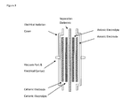
- FIG. 4 is a schematic illustration of an embodiment of an assembled, unionized, energy storage device as disclosed herein.
- the assembly can be flooded on both sides with insulating oil to act as transport media for the ions, and to increase the electronic resistance of the assembly, protecting it from arcing and other breakdown phenomena.
- FIG. 5 is a schematic illustration of an embodiment of an assembled energy storage device as disclosed herein in the ionized state. Electrolyte layers are attracted to each other across the barrier placing the system in compressive strain.
- FIG. 6 is a schematic illustration of an embodiment of an assembled and ionized storage device as disclosed herein with charge applied to the electrodes.
- FIG. 7 is a schematic illustration of an embodiment of an energy storage device having a ionic solid dielectric layer.
- FIG. 8 is a schematic illustration of an embodiment of an energy storage device having a ionic solid dielectric layer with charge applied to the conductive plates.
- FIG. 9 is a schematic illustration of an embodiment of an energy storage device having a plurality of ionic solid dielectric layers.
- FIG. 10 is a schematic illustration of an embodiment of an energy storage device having a plurality of ionic solid dielectric layers with charge applied to the conductive plates.
- Capacitors typically store charge on electrically conductive surfaces. These charge-bearing surfaces are separated by a dielectric; an electrical insulator with a bulk resistance greater than 10 6 ohm-cm. As a charge is placed on the material surfaces, an electrical field is established between the plates resulting in a voltage. The net charge stored within the capacitor is always zero.
- Charge can be added to the plates until the electric field becomes so strong that it breaks down the dielectric.
- One measure of the performance of a dielectric material is its permittivity, i.e., its capacitance per unit length. The higher the permittivity, the slower the electric field will build for a given amount of charge.
- the other measure of the performance of a dielectric is breakdown voltage, i.e., the electric field strength that can cause the dielectric to rupture (reported in volts per unit thickness of the dielectric).
- the dielectric constant, Epsilon Relative, E r for these materials is not a constant, but a function of voltage. Due to the configuration of charges within the polymer electrolyte, as the plate voltage of the capacitor increases, the dielectric constant will also increase. This effect can be explained by the ionic spacing of the charges along the polymer molecules of the electrolyte. As the plate electric field increases, the spaces between the charges also increases. As the space increases, the attractive force between the charges decreases by 1/distance 2 . The decrease in polymer charge attractive force makes polarization to the plate electric field easier which is, by definition, an increase in the dielectric constant.
- a capacitor typically can accept and deliver energy faster and with less loss than a battery. This makes capacitors more efficient and potentially more powerful than batteries.
- A is the surface area of the electrodes
- d is the space between the electrodes
- Q is the charge stored on the plates when an electric field of E is applied to the plates.
- Capacitors have the ability to be cycled thousands of times due to the lack of internal electrochemical reactions. However, capacitors typically have not been able to match the energy storage capability of a battery due to lack of available materials and structures that can tolerate electric fields having sufficient strength.
- EDLC electric double layer capacitor
- FIG. 2 illustrates two high surface area porous electrodes separated by a separator, and each including a current collector and activated carbon.
- FIG. 2 shows the alignment of electrolyte ions along the porous surface of each electrode, and the small separation of charges (d) resulting from the electric field when a charge is applied to the cell.
- the electrolyte solution enables extremely high capacitances but limits the voltage that can be applied to the cell.
- Organic solvents employed for the electrolyte solution typically break down at 3 volts (e.g., direct current).
- typical EDLC voltages are typically limited to 2.7 volts (e.g., direct current).
- the devices, methods, and systems disclosed herein can overcome at least some of these constraints by using, among other things, materials that have the required permittivity and breakdown voltage to store, charge, and discharge energy, preferably at performance levels equivalent or superior to the best lithium ion batteries.
- the present disclosure provides various embodiments of energy storage devices, and methods of making and using same.
- the energy storage device includes (preferably in order): a cationic electrode cover layer, a cationic electrode, a cationic exchange polymer electrolyte layer, a separation dielectric layer, an anionic exchange polymer electrolyte layer, an anionic electrode, and an anionic electrode cover layer.
- the device further includes a non-electrically conductive dielectric oil (e.g., a polydimethylsiloxane), preferably within one or more solid electrolyte layers.
- the device is configured to be initially placed in an ionized state, and optionally, can be configured to be further charged to store energy in an electrostatic mode.
- the dielectric is desiccated to improve performance.
- the separation dielectric layer has at least a first major surface and a second major surface and can function as an ion barrier layer.
- the separation dielectric layer can be made of a wide variety of materials including polymers such as, for example, polyesters (e.g., polyethylene terephthalate), fluorocarbon polymers (e.g., polytetrafluoroethylene), and vinyl polymers (e.g., polyvinyl chloride).
- Preferred properties of this layer are one or more of (i) a substantially high electronic resistance (e.g., greater than 10 14 Ohm-cm); (ii) no or substantially no ionic conductivity; and (iii) a high dielectric strength (e.g., greater than 15 kV/mm).
- the cationic exchange polymer electrolyte layer has at least a first major surface and a second major surface.
- the first major surface of the cationic exchange polymer electrolyte layer is adjacent a portion of the first major surface of the separation dielectric layer.
- the cationic exchange polymer electrolyte layer includes at least one polymer having a plurality of chemically bound negative ions and a plurality of electrostatically bound positive ions (e.g., hydrogen ions, H + ).
- cationic exchange polymer electrolytes can be used in the devices, methods, and systems disclosed herein.
- exemplary chemically bound negative ions include sulfonate, carboxylate, phosphate, phosphonate, and combinations thereof.
- Exemplary electrostatically bound positive ions include, for example, alkali metal ions (e.g., lithium, sodium, potassium, rubidium, and/or cesium), alkaline earth metal ions (e.g., calcium, strontium, and/or barium), and combinations thereof.
- the cationic exchange polymer electrolyte layer can include an optionally crosslinked cationic exchange polymer (e.g., a sodium cationic exchange polymer).
- the cationic exchange polymer electrolyte can be a polystyrene having sulfonate groups attached to the aromatic ring (e.g., in the ortho and/or para positions) of at least a portion of the styrene units.
- polystyrene having sulfonate groups attached to the aromatic ring (e.g., in the ortho and/or para positions) of at least a portion of the styrene units For example, polymers having pendant aryl sulfonate groups are described, for example, in U.S. Pat. No. 5,468,574 (Ehrenberg et al.), U.S. Pat. No. 5,677,074 (Serpico et al.), U.S. Pat. No. 5,679,482 (Ehrenberg et al.), U.S. Pat. No.
- the anionic exchange polymer electrolyte layer has at least a first major surface and a second major surface.
- the first major surface of the cationic exchange polymer electrolyte layer is adjacent a portion of the second major surface of the separation dielectric layer.
- the anionic exchange polymer electrolyte layer includes at least one polymer having a plurality of chemically bound positive ions and a plurality of electrostatically bound negative ions (e.g., chloride ions, Cl ⁇ ).
- anionic exchange polymer electrolytes can be used in the devices, methods, and systems disclosed herein.
- Exemplary chemically bound positive ions include ammonium (e.g., quaternary ammonium), phosphonium (e.g., quaternary phosphonium), sulfonium (e.g., tertiary sulfonium), and combinations thereof.
- Exemplary electrostatically bound negative ions include, for example, halides (e.g., chloride, fluoride, bromide, and/or iodide), pseudohalides (e.g., azides, isocyanides), SbF 6 ⁇ , PF 6 ⁇ , and combinations thereof.
- the anionic exchange polymer electrolyte layer can include an optionally crosslinked anionic exchange polymer (e.g., an iodide anionic exchange polymer).
- the anionic exchange polymer electrolyte can be a polystyrene having —CH 2 NR 3 + X ⁇ groups attached to the aromatic ring (e.g., in the ortho and/or para positions) of at least a portion of the styrene units, wherein each R can independently represent a C1-C10 alkyl group, and X can represent a halide.
- a particularly preferred anionic exchange polymer electrolyte can be a polystyrene having —CH 2 N(CH 3 ) 3 + I ⁇ groups attached to the aromatic ring of at least a portion of the styrene units, which can conveniently be prepared by aminating a chloromethylated polystyrene with a tertiary amine, and exchanging chloride for iodide.
- the general structures of the polymers used for the anionic and cationic exchange polymer electrolytes can be the same or different.
- the term “polymers” is intended to be broadly interpreted to include, for example, oligomers.
- polymers having the same general structure can be modified through chemical reactions (e.g., sulfonations) or substitution reactions of the polymers and/or the monomers used to prepare the polymers, to become anionic and/or cationic polymer exchange electrolytes.
- the general structure of the polymers can result in self assembly properties that can create nano-structure that can be important for ionic conduction and charge separation.
- the polymer to be sulfonated can have a high styrenic content and/or a controlled distribution of carbon-carbon double bonds.
- the exchange polymer electrolyte can be a highly sulfonated polymer composite.
- the polymer can be highly uniformly sulfonated (i.e. from about 25-100% sulfonated by weight), and may be utilized in the form of a sulfonated sheet or membrane. Processes for sulfonating polymers are described, for example, in Gilbert, Chem Rev (1962) 62:549-589; and German Patent No. DE 580,366.
- Sulfonation generally refers to an organic chemical reaction that leads to the formation of a carbon-sulfur bond.
- sulfonation at the aromatic ring by the reactive (sulfonating) compound usually occurs by replacing a hydrogen atom on the aromatic ring by a sulfonic acid residue functional group by means of an electrophilic aromatic substitution reaction.
- Sulfonated block copolymers may be produced by sulfonation reaction using, for example, sulfur trioxide, sulfuric acid, chlorosulfonic acid, and/or acetyl sulfate as the sulfonating agent.
- the sulfonated polymers could be used in their produced form, or in their acid, alkali metal salt, or ammonium salt (including complex amine) forms.
- the anionic and/or cationic exchange polymer electrolytes can include, for example, peptides, polypeptides, proteins, glycoproteins, biopolymers, and combinations thereof.
- the anionic and/or cationic exchange polymer electrolytes can include, for example, homopolymers and/or copolymers (e.g., a statistical, random, or block copolymer).
- the anionic and/or cationic exchange polymer electrolytes can include, for example, single or multiphase polymers and/or copolymers.
- the anionic and/or cationic exchange polymer electrolytes can include, for example, an ionomer.
- ionomers contain both polar and non-polar moieties, which each group together.
- the polar ionic moieties tend to cluster together and separate from the nonpolar backbone moieties, which allows for thermoplasticity, especially when heated. This increased thermoplasticity allows for increased energy storage and increased ability to cycle. Additionally, the non-ionic areas can exhibit adhesive properties. In certain embodiments, a balance between thermoplasticity and flow at a certain temperature can be desirable.
- the anionic and/or cationic exchange polymer electrolytes can include, for example, arene-containing linear side chains, non-arene-containing linear side chains, saturated linear side chains, unsaturated linear side chains, and flexible hydrocarbon linear side chains.
- the anionic and/or cationic exchange polymer electrolytes can be, for example, unsubstituted and/or substituted (e.g., substituted with heteroatoms such as oxygen, nitrogen, or other non-carbon atoms).
- the anionic and/or cationic exchange polymer electrolytes can are capable of being dissolved in chlorinated solvents, and may stay in solution at cold temperatures.
- an “alkene moiety” refers to a hydrocarbon chain containing at least one carbon-carbon double bond.
- An “arene moiety” refers to a monovalent or divalent aryl or heteroaryl group.
- An aryl group refers to hydrocarbon ring system including hydrogen, 6 to 18 carbon atoms, and at least one aromatic ring.
- the aryl group may be a monocyclic or polycyclic (e.g., bicyclic, tricyclic, or tetracyclic) ring system, which may include fused or bridged ring systems.
- Aryl groups include, but are not limited to, aryl groups derived from aceanthrylene, acenaphthylene, acephenanthrylene, anthracene, azulene, benzene, chrysene, fluoranthene, fluorene, as-indacene, s-indacene, indane, indene, naphthalene, phenalene, phenanthrene, pyrene, and triphenylene.
- an aryl group is derived from benzene.
- a heteroaryl group refers to a 5 to 14 membered ring system including hydrogen atoms, one to thirteen carbon atoms, one to six heteroatoms (e.g., nitrogen, oxygen, and/or sulfur), and at least one aromatic ring.
- the heteroaryl group may be a monocyclic or polycyclic (e.g., bicyclic, tricyclic, or tetracyclic) ring system, which may include fused or bridged ring systems.
- the nitrogen, carbon, and/or sulfur atoms in the heteroaryl radical may optionally be oxidized, and the nitrogen atom may optionally be quaternized.
- Examples include, but are not limited to, azepinyl, acridinyl, benzimidazolyl, benzindolyl, 1,3-benzodioxolyl, benzofuranyl, benzooxazolyl, benzothiazolyl, benzothiadiazolyl, benzo[b][1,4]dioxepinyl, benzo[b][1,4]oxazinyl, 1,4-benzodioxanyl, benzonaphthofuranyl, benzoxazolyl, benzodioxolyl, benzodioxinyl, benzopyranyl, benzopyranonyl, benzofuranyl, benzofuranonyl, benzothienyl (benzothiophenyl), benzothieno[3,2-d]pyrimidinyl, benzotriazolyl, benzo[4,6]imidazo[1,2-a]pyridinyl, carbazoly
- an “arene-containing linear side chain” refers to an unbranched hydrocarbon chain consisting only of carbon and/or hydrogen, wherein at least one carbon in the chain is replaced with an aryl or heteroaryl group, as defined above.
- non-arene-containing linear side chain refers to an unbranched hydrocarbon chain consisting only of carbon and/or hydrogen and containing no aryl or heteroaryl groups within the chain.
- an “unsaturated linear side chain” refers to an unbranched hydrocarbon chain consisting only of carbon and/or hydrogen and including at least one carbon-carbon double bond or at least one carbon-carbon triple bond.
- a “saturated linear side chain” refers to an unbranched hydrocarbon chain consisting only of carbon and/or hydrogen and containing no carbon-carbon double bonds and no carbon-carbon triple bonds.
- a “flexible hydrocarbon linear side chain” refers to a flexible connecting component as disclosed, for example, in U.S. Pat. No. 5,468,574 (Ehrenberg et al.) and U.S. Pat. No. 5,679,482 (Ehrenberg et al.).
- alternating copolymers include regular alternating A and B chemical or constitutional units; periodic copolymers contain A and B units arranged in a repeating sequence (e.g., (A-B-A-B-B-A-A-A-B-B)n); random copolymers including random sequences of monomer A and monomer B units; statistical copolymers including an ordering of distinct monomers within the polymer sequence that obeys statistical rules; block copolymers that include two or more homopolymer subunits linked by covalent bonds such as, for example, diblock, tri-block, tetra-block or other multi-block copolymers. See, for example, IUPAC, Pure Appl Chem (1996) 68:2287-2311.
- any of the copolymers described may be linear (including a single main chain), or branched (including a single main chain with one or more polymeric side chains).
- Branched copolymers that have side chains that are structurally distinct from the main chain are known as graft copolymers.
- Individual chains of a graft copolymer may be homopolymers or copolymers, and different copolymer sequencing is sufficient to define a structural difference.
- an A-B diblock copolymer with A-B alternating copolymer side chains is considered a graft copolymer.
- Other types of branched copolymers include star, brush, and comb copolymers. Any one of these copolymers, or any mixture thereof, may be utilized with certain aspects of the disclosed devices.
- the anionic and/or cationic exchange polymer electrolytes can include, for example, a polymer including at least one block.
- the polymer is a thermoplastic block copolymer.
- the polymer is a block copolymer that includes differentiable monomeric units.
- at least one of the monomeric units of the block copolymer includes an arene moiety-containing unit.
- at least one block includes a non-arene moiety-containing unit.
- the block copolymer includes at least two monomeric units arranged in statistically random order.
- the block copolymer includes at least two monomeric units arranged in ordered sequence.
- the anionic and/or cationic exchange polymer electrolytes can include, for example, not only polymers or block copolymers, but also copolymers with other ethylenically unsaturated monomers (e.g., acrylonitrile, butadiene, methyl methacrylate, and combinations thereof).
- ethylenically unsaturated monomers e.g., acrylonitrile, butadiene, methyl methacrylate, and combinations thereof.
- a block copolymer can be a block copolymer having at least a first block of one or more mono alkene-arene moieties, such as styrene, ring-substituted styrene, ⁇ -substituted styrene, or any combination thereof; and a second block of a controlled distribution copolymer of a diene moiety and a mono alkene-arene moiety.
- the block copolymer can be any configuration of “A” and “B” blocks, and such block copolymers can be generated by a wide variety of methods known to one of skill in the art.
- a “mono alkene-arene moiety” refers to one or more alkene moieties, as defined above, covalently bonded to an arene moiety, as defined above.
- An example of a “mono alkene-arene moiety” is styrene.
- a “poly alkene-arene moiety” refers to a two or more mono alkene-arene moieties, as defined above, covalently bonded to each other to form a chain including two or more mono alkene-arene moieties.
- An example of a “poly alkene-arene moiety” is polystyrene.
- a “diene moiety” refers to a hydrocarbon chain containing two carbon-carbon double bonds. In certain embodiments, the diene moiety may be conjugated, unconjugated, or cumulated.
- block copolymers include, for example, those described in U.S. Pat. No. 4,248,821 (Van Dellen), U.S. Pat. No. 5,239,010 (Balas et al.), U.S. Pat. No. 6,699,941 (Handlin et al.), U.S. Pat. No. 7,001,950 (Handlin, Jr. et al.), U.S. Pat. No. 7,067,589 (Bening et al.), U.S. Pat. No. 7,169,848 (Bening et al.), U.S. Pat. No. 7,169,850 (Handlin, Jr. et al.), U.S. Pat.
- the anionic and/or cationic exchange polymer electrolytes can include, for example, a statistical copolymer.
- a statistical copolymer is used herein consistent with the commonly understood usage in the art. See, for example, Odian, Principles of Polymerization, 1991.
- Statistical copolymers can be derived from the simultaneous polymerization of two monomers and can have, for example, a distribution of the two monomeric units along the copolymer chain, which follows Bemoullian (zero-order Markov), or first or second order Markov statistics.
- the polymerization may be initiated by free radical, anionic, cationic, or coordinatively unsaturated (e.g., Ziegler-Natta catalysts) species.
- Ring et al. (Pure Appl Chem (1985) 57:1427), statistical copolymers can be the result of elementary processes leading to the formation of a statistical sequence of monomeric units that do not necessarily proceed with equal probability.
- Bernoullian statistics is essentially the statistics of coin tossing; copolymers formed via Bernoullian processes have the two monomers distributed randomly and are referred to as random polymers.
- a free radical copolymerization for the active end, in the case of one embodiment, a styryl or butadienyl radical, to have essentially no selectivity for styrene vs. butadiene. If so, the statistics will be Bernoullian, and the copolymer obtained will be random.
- block copolymers can be derived from the simultaneous copolymerization of two monomers when the preference of the propagating chain ends for adding the opposite monomers is very low. The resulting polymer would be categorized as a block copolymer for the purposes of the present disclosure.
- Statistical copolymers generally display a single glass transition temperature.
- Block and graft copolymers typically display multiple glass transitions, due to the presence of multiple phases.
- Statistical copolymers are, therefore, distinguishable from block and graft copolymers on this basis.
- the single glass transition temperature reflects homogeneity at the molecular level. An additional consequence of this homogeneity is that statistical copolymers, such as those of styrene and butadiene, when viewed by electron microscopy, display a single phase morphology with no microphase separation.
- block and graft copolymers of styrene/butadiene are characterized by two glass transition temperatures and separation into styrene-rich domains and butadiene-rich domains.
- membranes which are produced from statistical copolymers originally having a single glass transition temperature and a single phase morphology do not necessarily exhibit a single phase morphology or a single glass transition temperature after sulfonation because of chemical changes in the polymer effected by the sulfonation, in combination with the physical changes effected by the casting processes of the present disclosure.
- Pseudo-random copolymers are a subclass of statistical copolymers which result from a weighted change in the monomer incorporation that skews the distribution from a random arrangement (i.e. Bernoullian) that is defined as statistical. Linear arrangements have been described here, but branched or grafted including star arrangements of monomers are possible as well.
- block copolymers of styrene and hydrogenated butadiene, isoprene, or equivalent olefin can be employed.
- the block architecture can be monomeric units including diblock, triblock, graft-block, multi-arm starblock, multiblock, segmented, tapered block, or any combination thereof.
- the polymer includes moieties or segments including unsaturated carbon-carbon double bonds, which are able to be sulfonated.
- Some examples of such polymers include, but are not limited to, polybutadiene and/or polyisoprene.
- certain embodiments disclosed herein relate to the sulfonation of polymers including one or more of the following moieties: alkane, alkene, alkyne, and arene, each of which may be optionally substituted by one or more of the following functional groups: carboxylic acid, urea, ester, urethane (carbamate), alkene, amide, benzene, pyridine, indole, carbonate, thioester, arcylate/acrylic, ether, amidine, ethyl, acid versions of aliphatic compounds that contain alkenes, alkanes or alkynes, imidazole, oxazole, and other possible combinations of heteroatom containing groups susceptible to loss of water and/or disassembly.
- alkane alkene
- alkyne alkyne
- arene each of which may be optionally substituted by one or more of the following functional groups: carboxylic acid, urea, ester, urethan
- the weight of the polymers utilized in the present disclosure are preferably at least approximately 1 kilo Dalton (KD), 2 KD, 5 KD, 10 KD, 15 KD, 20 KD, 25 KD, 30 KD, 40 KD, 50 KD, 60 KD, 70 KD, 80 KD, 90 KD, or any value therebetween or greater.
- KD kilo Dalton
- polymers or blocks of polymers that may be included in certain embodiments include, but are not limited to, polyethylene (PE), polypropylene (PP), polyethylene oxide (PEO), polystyrene (PS), polyesters, polycarbonate (PC), polyvinyl chloride (PVC), nylon, halogenated polymers or copolymers such as perfluorinated copolymers, poly(methyl methacrylate) (PMMA), acrylonitrile butadiene styrene (ABS), polyamide (PA), polyurethane (PU), polytetrafluoroethylene (PTFE), polylactic acid (PLA), polyvinylidene chloride (PVDC), styrene-butadiene rubber (SBR), styrene-ethylene/butylenes-styrene (SEBS); styrene-ethylene/propylene-styrene (SEPS), ethylene-styrene interpolymer (ESI), styrene inter
- the degree of polymerization generally refers to the number of repeat units or segments in an average polymer chain at a particular time in a polymerization reaction, where length is measured by monomer segments or units.
- Preferable lengths include, but are not limited to, approximately 500 monomer units, 1000 monomer units, 5000 monomer units, 10,000 monomer units, 25,000 monomer units, 50,000 monomer units, 100,000 monomer units, 200,000 monomer units, 300,000 monomer units, 500,000 monomer units, 700,000 monomer units, or greater or any value there between.
- the degree of polymerization may also be a measure of the molecular weight of a polymer. Thus, the degree of polymerization is equal to the total molecular weight of the polymer divided by the total molecular weight of the repeating unit or segment. Polymers with different total molecular weights but identical composition may exhibit different physical properties. Generally, a greater degree of polymerization correlates with a greater melting temperature and greater mechanical strength.
- the polymer can include a multiphase large molecular chain polymer.
- the multiphase large molecular chain polymer includes one or more arene-containing linear side chains, non-arene-containing linear side chains, saturated linear side chains, unsaturated linear side chains, and/or flexible hydrocarbon linear side chains.
- the exchange polymer electrolytes can include a wide variety of anion-conducting groups so long as they are such groups that the material can display sufficient anion conductivity and moisture transfer properties.
- anion-conducting groups include an ammonium group optionally substituted with an alkyl group have 1 to 10 carbon atoms; a pyridinium group having a methyl group or an ethyl group bounded to the nitrogen atom or a pyridyl group that has formed a salt with an acid; an imidazolium group having a methyl group or an ethyl group bonded to the nitrogen atom or an imidazolyl group that has formed a salt with an acid; a phosphonium group optionally substituted with a methyl group or an ethyl group or the like.
- the anion-conducting groups into polymer block (A) there is no particular restriction, and they can be introduced either into the aromatic vinyl units or into other monomer units.
- the amount of the anion-conducting group introduced can be selected depending upon the application purpose, but usually, in order to display sufficient ion conductivity for use as a polymer exchange electrolyte, the amount is preferably sufficient such that the ion exchange capacity of the block polymer is 0.3 to 4 milliequivalents/g. In certain embodiments, introduction of larger amounts can result in low mechanical strength and/or low long term durability.
- an anion-conducting group into the resulting block copolymer can be conducted by a known method.
- the obtained block copolymer can be chloromethylated, and then reacted with an amine or a phosphine.
- the chloride ions can be replaced with hydroxide ions or other acid anions.
- chloromethylation methods known in the art can be used.
- a method including adding a chloromethylating agent and a catalyst into a solution or suspension of the block polymer in an organic solvent to chloromethylate the block copolymer can be used.
- organic solvents including, for example, halogenated hydrocarbons (e.g., chloroform or dichloroethane) can be used.
- Chloromethylating agents including, for example, chloromethyl ether and/or hydrochloric acid-paraformaldehyde can be used, and catalysts including, for example, tin chloride and/or zinc chloride can be used.
- a wide variety of methods for reacting an amine or a phosphine with a chloromethylated block polymer can be used.
- a method including adding an amine or phosphine (e.g., as a solution in an organic solvent) to a solution or suspension of a chloromethylated block copolymer in an organic solvent, or a material formed form the solution or suspension can be used.
- organic solvents can be used for preparing the solution or suspension including, for example, methanol, ethanol, acetone, and/or acetonitrile.
- amines can be used including, for example, ammonia, primary amines (e.g., methyl amine), secondary amines (e.g., dimethyl amine), and combinations thereof can be used to obtain a weakly basic anion exchange polymer; tertiary amines (e.g., trimethyl amine, triethyl amine, dimethylethanol amine, methyl diethanol amine, and/or triethanol amine) can be used to obtain a strongly basic anion exchange membrane; and diamines or polyamines (e.g., ethylene diamine or tetramethyl diaminopropane) can be used to obtain an anion exchange membrane having ion exchange groups bonded to one another.
- primary amines e.g., methyl amine
- secondary amines e.g., dimethyl amine
- tertiary amines e.g., trimethyl amine, triethyl amine, dimethylethanol amine, methyl diethanol amine,
- a chloride ion can be introduced as an anion-conducting group that can optionally be converted to a hydroxide ion or another acid anion if desired.
- a wide variety of methods for converting the chloride ion to another ion can be used.
- a chloride ion can be converted to a hydroxide ion conducting group by immersing a chloride ion-containing block copolymer into an aqueous solution of sodium hydroxide or potassium hydroxide.
- the ion exchange capacity of an anion-conducting copolymer can be measured using a wide variety of analytical methods known in the art including, for example, titration methods, infrared spectroscopic analysis, proton nuclear magnetic resonance (1H NMR) spectroscopy, elemental analysis, or combinations thereof.
- the cationic electrode has at least a first major surface and a second major surface.
- the first major surface of the cationic electrode is adjacent at least a portion of the second major surface of the cationic exchange polymer electrolyte layer.
- the anionic electrode has at least a first major surface and a second major surface.
- the first major surface of the anionic electrode is adjacent at least a portion of the second major surface of the anionic exchange polymer electrolyte layer.
- the electrodes in the devices, methods, and systems disclosed herein can have metal or otherwise electrically conductive surfaces.
- the anode, the cathode, or both can be a porous metal or carbon plate.
- the electrodes can have high surface area and can optionally be porous.
- the electrodes include composites such as, for example, an anode including an anionic exchange polymer electrolyte with a plurality of particles, and a cathode including a cationic exchange polymer electrolyte with a plurality of particles. See U.S. Pat. No. 5,136,474 (Sarangapani et al.) for additional examples of composite electrodes.
- the particles can be applied to the face of an electrode by casting, vapor depositing, spraying, or any other process that allow for application, preferably in a uniform manner. Once applied to the face of the electrode, the particles can increase the functional surface area, resulting in an increase in capacitance of the capacitor. In certain embodiments, the surface area can be increased by at least 100 times, at least 500 times, at least 1,000 times, at least 10,000 times, at least 50,000 times, at least 100,000 times, or even more.
- anionic exchange polymer electrolytes and cationic exchange polymer electrolytes can be used for composite electrodes. Exemplary anionic exchange polymer electrolytes and exemplary cationic exchange polymer electrolytes are described herein above. Additional exemplary polymer electrolytes useful for composite electrodes are described in U.S. Pat. No. 7,990,679 (Ehrenberg et al.); and U.S. Patent Application Publication No. 2012/0320497 (Ehrenberg).
- the polymer electrolytes can act to hold the particles of the electrode together.
- the polymer electrolytes can act as an adhesive to bind a conductive particle electrode to the interior face of an outer layer (e.g. metal foil).
- the polymer electrolytes can also serve a dielectric function by modulating the electric field at the surface of the particles, and increasing the charge capacity of the electrode and the cell.
- the polymer electrolytes can also fill a void between the particles, preventing any voids from creating paths to the dielectric layer.
- the particles are conductive.
- Useful particles can include, for example, carbon, a metal, a metal oxide, or other metal-containing particles.
- Useful metals include, for example, nickel, titanium (e.g., titanium dioxide), lead, lithium, silver, and copper.
- Other electrically conductive particles include phthalocyanine oligomers and other electrically conductive materials (e.g., organic molecules and polymers).
- the nanoparticles include carbon.
- the particles are particles having high surface area (e.g., greater than 1000 meters 2 /g and in some embodiments greater than 2000 meters 2 /g) such as nanoparticles.
- the nanoparticles are carbon particles (e.g., graphite).
- nanoparticles can be used to increase the surface area of the composite electrode.
- the three-dimensional surface of the nanoparticles can allow for increased functional surface area upon which the charge may build the electric field within each electrode layer of the energy storage device.
- the nanoparticles utilized by certain exemplary embodiments may be of any shape or form, preferably spheroidal, and can be round, oval, irregular, pyramidal, conical, rhomboidal, or any variation of these or other shapes.
- the average diameter of the nanoparticles is at most 150 nm, at most 125 nm, at most 100 nm, at most 75 nm, at most 50 nm, at most 25 nm, at most 10 nm, at most 5 nm, at most 2.5 nm, at most 2 nm, at most 1 nm, or even less.
- the diameter is taken to be the largest dimension of the particle.
- graphite composite electrodes can be constructed by mixing graphite (e.g., conductive graphite powders), which are commercially available with surface areas far exceeding 2400 meter 2 per gram, with the corresponding polymer electrolyte.
- graphite e.g., conductive graphite powders
- the term graphite is intended to include graphene, a flat mono-layer of carbon atoms.
- the structure of the composite electrodes may reduce the effective surface area of the graphite, it can produce a balance between ionic and electronic conductive structures. It is expected that 20-40% of the particle surface area can still be available for redox plating and electrostatic charging. At modest graphite loadings per centimeter 2 of composite electrode, surface area enhancements of 10 4 are expected.
- the loading of conductive graphite powders in the graphite composite electrodes is high enough to achieve electrical conductivity, but not so high as to impede the dielectric access of ions to the conductive surfaces.
- graphite composite electrodes can include 17 to 50 volume percent conductive graphite powders.
- Certain other embodiments disclosed herein include flat sheets of composite electrode to form energy storage device cells.
- the flat sheets of very thin cells forming the energy storage device can allow for versatility of shape and size of the device.
- the flat cells can allow for the use of a prismatic shape, or other shapes for the devices, to generate energy storage devices that are efficient in space and volume.
- the thin, flat sheets can be laminated together to form a cell of the energy storage device.
- the particular processes of forming the materials and assembling the cells can allow for high speed automation, thus reducing the overall cost of manufacturing the devices.
- the sheet material devices can be stacked in a prismatic, or other arrangement, that can allow for generation of energy storage devices having the ability to cycle and re-cycle with good power delivery.
- the anionic electrode cover layer preferably including an insulating material, is configured to provide a gas tight seal around the anionic exchange polymer electrolyte layer and the anionic electrode to exposed portions of the second major surface of the separation dielectric layer.
- the anionic electrode cover layer also includes a second optional vacuum port and a second electrical contact in electrical communication with the anionic electrode.
- the second vacuum port can include, for example, an electrically conductive metal, in which case, the second vacuum port can also be the second electrical contact.
- the cationic electrode cover layer preferably including an insulating material, is configured to provide a gas tight seal around the cationic exchange polymer electrolyte layer and the cationic electrode to exposed portions of the first major surface of the separation dielectric layer.
- the cationic electrode cover layer also includes a first optional vacuum port and a first electrical contact in electrical communication with the cationic electrode.
- the first vacuum port can include, for example, an electrically conductive metal, in which case, the first vacuum port can also be the first electrical contact.
- the dielectric and electrode layers, prior to assembly, can be impregnated with an oil (e.g., a non-electrically conductive dielectric oil).
- the oil can be chosen from a group of small molecule oils that are known to have very high breakdown voltages and bulk resistances, along with modest dielectric constants. Such oils are typically used in high voltage transformers and switches as dielectric insulation to prevent arcing.
- polydimethylsiloxane such as that available under the trade designation CLEARCO STO-50 silicone transformer oil from Clearco Products Co., Inc., Bensalem, Pa.
- Such an oil impregnated into the electrolyte structure can be absorbed into the charge domains to displace, for example, any residual water, and increase the bulk electrical resistivity and ionic conductivity of the structure (e.g., act as an ion conductivity enhancer) and help to protect the structure from arcing or other breakdown phenomena.
- the oil can also act as a media for the transport of ions to the electrodes for oxidation or reduction.
- the present disclosure provides a method of placing an energy storage device in an ionized state.
- the method includes: providing an energy storage device as described herein; applying a negative potential to the first electrical contact of the cationic electrode cover layer effective to cause at least a portion (and preferably substantially all) of the electrostatically bound positive ions (e.g., hydrogen ions, H + ) to migrate to the cationic electrode and be reduced to a neutral species (e.g., molecular hydrogen, H 2 ); applying a positive potential to the second electrical contact of the anionic electrode cover layer effective to cause at least a portion (and preferably substantially all) of the electrostatically bound negative ions (e.g., chloride ions, Cl ⁇ ) to migrate to the anionic electrode and be oxidized to a neutral species (e.g., molecular chlorine, Cl 2 ); optionally applying at least a partial vacuum (and preferably a vacuum) to the first optional vacuum port of the cationic electrode cover layer effective to remove at least
- the present disclosure provides energy storage devices in an ionized state.
- energy storage devices as disclosed herein can be placed in an ionized state by the methods disclosed herein.
- the energy storage device in the ionized state is in an uncharged state.
- the energy storage device in the ionized state is in an electrically neutral state having no potential across the first and second electrical contacts.
- the energy storage device has a high dielectric constant.
- the anionic exchange polymer electrolyte layer and the cationic exchange polymer electrolyte layer of the energy storage device in the ionized state are under compressive strain.
- the present disclosure also provides methods of storing energy using an energy storage device in an ionized state as described herein.
- the method includes applying a positive potential to the first electrical contact of the cationic electrode cover layer and negative potential to the second electrical contact of the anionic electrode cover layer under conditions effective to electrostatically store charge on the device.
- the storage of charge on the device is sufficient to at least partially relieve (and preferably fully relieve) compressive strain between the anionic exchange polymer electrolyte layer and the cationic exchange polymer electrolyte layer. As the dielectric relaxes from compression to tension, it will store electrical energy through the relationship of force ⁇ distance.
- the present disclosure provides a method of storing energy.
- the method includes: providing an energy storage device as disclosed herein; applying a negative potential to the first electrical contact of the cationic electrode cover layer effective to cause substantially all of the electrostatically bound positive ions to migrate to the cationic electrode and be reduced to a neutral species; applying a positive potential to the second electrical contact of the anionic electrode cover layer effective to cause substantially all of the electrostatically bound negative ions to migrate to the anionic electrode and be oxidized to a neutral species; optionally applying at least a partial vacuum to the first optional vacuum port of the cationic electrode cover layer effective to remove at least a portion of the reduced neutral species; and optionally applying at least a partial vacuum to the second optional vacuum port of the anionic electrode cover layer effective to remove at least a portion of the oxidized neutral species; and further applying a positive potential to the first electrical contact of the cationic electrode cover layer and negative potential to the second electrical contact of the anionic electrode cover layer under conditions effective to electrostatically store charge on the device
- the present disclosure provides a method of preparing an ionic solid dielectric material.
- the method includes: providing an anionic exchange polymer electrolyte solution including at least one polymer having a plurality of chemically bound positive ions and a plurality of electrostatically bound negative ions (e.g., chloride ions); and providing a cationic exchange polymer electrolyte solution including at least one polymer having a plurality of chemically bound negative ions and a plurality of electrostatically bound positive ions (e.g., hydrogen ions).
- an anionic exchange polymer electrolyte solution including at least one polymer having a plurality of chemically bound positive ions and a plurality of electrostatically bound negative ions (e.g., chloride ions)
- a cationic exchange polymer electrolyte solution including at least one polymer having a plurality of chemically bound negative ions and a plurality of electrostatically bound positive ions (e.g., hydrogen ions).
- the method further includes combining the anionic exchange polymer electrolyte solution and the cationic exchange polymer electrolyte solution under conditions effective to allow at least a portion of the plurality of chemically bound positive ions of the anionic exchange polymer electrolyte to ionically associate with at least a portion of the plurality of chemically bound negative ions of the cationic exchange polymer electrolyte and form the ionic solid dielectric material.
- the ionic solid dielectric material can be prepared by mixing a cationic exchange polymer electrolyte and an anionic exchange polymer electrolyte in solution. The mixing can be done at a convenient temperature (e.g., room temperature to 50° C.). As they are mixed, the opposite polarity of the molecules can attract each other. As they become ionically associated, the mobile ions associated with the molecules (e.g., H + for the cationic and CF for the anionic) are freed to form a neutral species (e.g., hydrochloric acid, HCl).
- the formed ionic solid dielectric material can be cast as a film.
- the film can be cast as multiple layers. For example, each layer can be allowed to reach its gel point before casting a subsequent layer, and films of varying thickness can be created by iterating the casting process.
- the casting process is done under controlled humidity conditions (e.g., under a hood). The casting can be done at a convenient temperature (e.g., room temperature to 50° C.).
- the formed ionic solid dielectric material can be cast as a film on a substrate (e.g., a release substrate or a conductive plate), conveniently on a vacuum table, for example.
- a substrate e.g., a release substrate or a conductive plate
- the casting can be done on a non-stick release liner (e.g., a silicone coated polyethylene terephthalate (PET) film) or onto the capacitor conduction plate itself.
- PET polyethylene terephthalate
- the capacitor plate can be solid or porous with compositions ranging from metal to porous carbon.
- the conductive plate can be selected from the group consisting of a metal conductive plate, a carbon conductive plate, a porous metal conductive plate, a porous carbon conductive plate, and a carbon composite electrode.
- the electrolyte layer can be washed with deionized, distilled water to remove at least part (and substantially all) the HCl, and then dried. In certain embodiments, multiple washing cycles may be used to allow the mobile ions to diffuse from the film into the wash liquid.
- Films can be dried by a wide variety of suitable methods including, for example, air drying and drying in a vacuum oven (e.g., at 40-45° C.). After drying, a plastic ionic solid is formed. Within the layer, the molecules are ionically attracted to each other by their covalently bound charges. This ionic solid is can then be placed between two plates as the dielectric for the capacitor.
- the film of the formed ionic solid dielectric material further can include at least a portion of the negative ions that were electrostatically bound to the anionic exchange polymer electrolyte, and at least a portion of the positive ions that were electrostatically bound to the cationic exchange polymer electrolyte.
- at least a portion of the negative and/or positive ions from the ionic solid dielectric film can optionally be at least partially removed (and in preferred embodiments substantially entirely removed) by washing the film with, for example, deionized, distilled water, to remove at least part (and substantially all) the HCl, and then dried.
- multiple washing cycles may be used to allow the mobile ions to diffuse from the film into the wash liquid.
- Films can be dried by a wide variety of suitable methods including, for example, air drying and drying in a vacuum oven (e.g., at 40-45° C.). After drying, a plastic ionic solid is formed. Within the layer, the molecules are ionically attracted to each other by their covalently bound charges. This ionic solid is can then be placed between two plates as the dielectric for the capacitor.
- the present disclosure provides an ionic solid dielectric material.
- the ionic solid dielectric material includes: at least one polymer having a plurality of chemically bound positive ions; and at least one polymer having a plurality of chemically bound negative ions, wherein at least a portion of the plurality of chemically bound positive ions ionically associate with at least a portion of the plurality of chemically bound negative ions.
- the present disclosure provides ionic solid dielectric materials prepared by methods disclosed herein.
- the present disclosure provides an energy storage device that includes: a first conductive plate; a second conductive plate; and at least one ionic solid dielectric layer between the first conductive plate and the second conductive plate.
- the at least one ionic solid dielectric layer includes an ionic solid dielectric material as described herein.
- suitable conductive plates e.g., electrodes
- at least one conductive plate includes a metal or carbon conductive plate such as a porous metal or carbon plate (e.g., a carbon composite electrode).
- the conductive plate can be selected from the group consisting of a metal conductive plate, a carbon conductive plate, a porous metal conductive plate, a porous carbon conductive plate, and a carbon composite electrode.
- the device can optionally include a non-electrically conductive dielectric oil as described herein (e.g. polydimethylsiloxane), for example, at least partially within the at least one ionic solid dielectric layer.
- the device is configured to be charged to store energy in an electrostatic mode.
- the present disclosure provides a method of storing energy.
- the method includes: providing an energy storage device that includes a first conductive plate, a second conductive plate, and at least one ionic solid dielectric layer between the first conductive plate and the second conductive plate; and applying a field negatively polarized with respect to the first conductive plate and positively polarized with respect to the second conductive plate under conditions effective to electrostatically store charge on the device.
- conditions effective to store charge on the device include applying a field having a potential of at least 1 volt direct current, and in certain embodiments a potential of greater than 1 volt direct current.
- conditions effective to store charge on the device include applying a field having a potential of no greater than the breakdown voltage of the ionic solid dielectric layer.
- the present disclosure provides systems for storing and discharging energy that include one or more energy storage devices as disclosed herein; and a means for applying a field negatively polarized with respect to the first conductive plate and positively polarized with respect to the second conductive plate under conditions effective to electrostatically store charge on the device (e.g., using a current source such as a direct current source, which can optionally be a continuous current source); and a means for discharging energy from electrostatically stored charge on the device (e.g., using a resistive and/or mechanical drain, such as heaters and/or motors).
- a current source such as a direct current source, which can optionally be a continuous current source
- a means for discharging energy from electrostatically stored charge on the device e.g., using a resistive and/or mechanical drain, such as heaters and/or motors.
- Multiple cells can be connected in parallel, for example, by a bus accessing the tabs on each cell. Stacking these capacitors cells in a prismatic arrangement can allow for the creation of an energy storage device with superior specific energy, energy density, and specific power that retains typical capacitor cycling and round trip energy efficiency characteristics.
- packaging the cells in parallel can divide cell resistance to create a low equivalent series resistance cell pack. The charge levels of the cell pack can be monitored to reduce or prevent current inrush or discharge, which can reduce or prevent overheating of the assembly. Appropriate cooling methods can optionally be used for cell packs. Individual cells can be fused so as to reduce the chance of a pack meltdown in the event of shorts in one or more individual cells.
- FIG. 3 Each cell consists of 9 components: the three dielectric layers, two electrodes, two electrically insulating cover layers that seal out external gases, and two metal vacuum ports that also function as the electrical contacts to the cell.
- the metal vacuum ports are in physical and electrical contact with the dielectric electrodes.
- the ions within the anionic layer are chloride ions (Cl ⁇ ).
- the ions with the cationic layer are hydrogen ions (i.e., protons, H + ).
- a potential is applied that causes the free exchange ions within the electrolyte to be pulled from their covalently bound counter ions.
- a negative potential is applied to the cationic electrode through the metal vacuum contact.
- a positive potential is applied to the anionic electrode through its metal vacuum contact.
- the ions are pulled to the electrodes and are electrochemically oxidized and reduced: Cl ⁇ ⁇ Cl 0 , H + ⁇ H 0 .
- These monatomic atoms are unstable and will bind to other similar atoms to for form a gas: Cl 2 , and H 2 .
- the cell is placed under vacuum to facilitate the removal of the gases. This is shown in FIG. 4 .
- the cell is now in an ionized state as shown in FIG. 5 . However, it is in an uncharged state and is electrically neutral.
- the cell electrodes have no potential as all the charge taken from or placed onto them as used to electrochemically create Cl 2 and H 2 gasses.
- the cell will have a very high dielectric constant as there are opposite polarity matching charges within the cell layers. These charges are separated by the middle non-electrolyte dielectric layer. These opposite polarity charges will establish a strong attractive electrostatic field between them. This electrostatic field causes the electrolyte material layers to undergo compressive strain as the charges move closer to each other. This is shown in FIG. 5 . Thus, as the dielectric polarizes, the dielectric constant increases and the dielectric loss of the structure is reduced.
- the voltage required to ionize the structure shown in FIG. 6 is a function of the charge density of the electrolyte.
- a charge density electrolyte of 2 MEQ per gram will require several thousand volts to fully ionize. To fully relieve the compressive strain the voltage on the electrodes must be equal to the ionization voltage.
- the amount of energy the cell will store is very large.
- the energy storage is proportional to the square of the electrode voltage.
- the complex solution was prepared by mixing 4 g of sulfonated SEBS polymer/THF/DEC/n-propanol solution (75 mole %, 18.1% solid) and 170 g of triethylammonium SEBS chloride polymer/ethanol/chloroform solution (76 mole %, 2.4% solid) under rapid stirring at 40-45° C. Large colloidal aggregates formed after mixing. Continuous stirring of the complex solution at the 40-45° C. for an extended period time redissolved the large colloidal aggregates yielding a clear solution. Thin films of the polyelectrolyte complex were prepared by multilayer-casting using wire wound rods. The dried thin film was first soaked in DI water for approximately 2 to 3 hours, washed with DI water several times, and then air dried.
- FIG. 7 The following is a description of one embodiment of an energy storage cell configuration as illustrated in FIG. 7 .
- This configuration uses a single dielectric layer of ionic solid dielectric material positioned between two conductive plates.
- the ionic solid dielectric material can be prepared, for example, as described in Example 2. This ionic solid is can then be placed between two plates as the dielectric for the capacitor.
- FIG. 8 When an external potential is applied to charge the plates, an internal field develops as illustrated in FIG. 8 .
- the internal field applies force to the molecules and places them in tension.
- the force is applied to every molecule in the dielectric that has covalently bound fixed charges attached.
- energy is stored in the capacitor through the relationship of force ⁇ distance.
- FIG. 9 The following is a description of one embodiment of an energy storage cell configuration as illustrated in FIG. 9 .
- This configuration uses multiple dielectric layers of ionic solid dielectric material positioned between two conductive plates.
- This example illustrates the use of different ionic solid dielectric materials in the different dielectric layers.
- These layers are shown in FIG. 9 are illustrate dielectric layers adjacent the conductive plates that include a first ionic solid dielectric material (i.e., Type 1 ionic solid dielectric material), and a dielectric layer between the first two dielectric layers that includes a second ionic solid dielectric material (i.e., Type 2 ionic solid dielectric material).
- energy storage devices can be created that include more or less dielectric layers.
- energy storage devices can be created that include more different types of ionic solid dielectric materials (e.g., up to as many different types of ionic solid dielectric materials as there are dielectric layers).
- the ionic solid dielectric materials and resulting layers can differ in physical, chemical, structural (e.g., nanostructure), and/or electrical properties (e.g., charge density). Structures such as those illustrated in FIG. 9 can be advantageous for increasing the bulk resistance and dielectric strength of the dielectric, which can preferably extend the energy storage capability of the device by being capable of sustaining higher voltages.
- FIG. 10 When an external potential is applied to charge the plates, an internal field develops as illustrated in FIG. 10 .
- the internal field applies force to the molecules and places them in tension.
- the force is applied to every molecule in the dielectric that has covalently bound fixed charges attached.
- energy is stored in the capacitor through the relationship of force ⁇ distance.
- hybrid energy storage devices combining ionic solid dielectric layers and polarized layers.
- such hybrid energy storage devices have the capability of increasing the performance of the resulting capacitors.
Abstract
Description
Charge=Capacitance×Voltage
Capacitance=(Permittivity of the dielectric×A)/d
Stored Energy=½ Capacitance×Voltage2
Referring to
Claims (16)
Priority Applications (1)
| Application Number | Priority Date | Filing Date | Title |
|---|---|---|---|
| US13/750,309 US9293269B2 (en) | 2012-02-08 | 2013-01-25 | Ultracapacitor tolerating electric field of sufficient strength |
Applications Claiming Priority (2)
| Application Number | Priority Date | Filing Date | Title |
|---|---|---|---|
| US201261596535P | 2012-02-08 | 2012-02-08 | |
| US13/750,309 US9293269B2 (en) | 2012-02-08 | 2013-01-25 | Ultracapacitor tolerating electric field of sufficient strength |
Publications (2)
| Publication Number | Publication Date |
|---|---|
| US20140035540A1 US20140035540A1 (en) | 2014-02-06 |
| US9293269B2 true US9293269B2 (en) | 2016-03-22 |
Family
ID=50024844
Family Applications (1)
| Application Number | Title | Priority Date | Filing Date |
|---|---|---|---|
| US13/750,309 Expired - Fee Related US9293269B2 (en) | 2012-02-08 | 2013-01-25 | Ultracapacitor tolerating electric field of sufficient strength |
Country Status (1)
| Country | Link |
|---|---|
| US (1) | US9293269B2 (en) |
Cited By (2)
| Publication number | Priority date | Publication date | Assignee | Title |
|---|---|---|---|---|
| US10672564B2 (en) | 2018-09-23 | 2020-06-02 | Kirk W. Rosener | Electret energy storage system |
| US11081280B2 (en) | 2018-02-06 | 2021-08-03 | Ehrenberg Industries Corporation | Ionomeric polymer and multilayer capacitor and additives |
Families Citing this family (17)
| Publication number | Priority date | Publication date | Assignee | Title |
|---|---|---|---|---|
| WO2012033827A1 (en) | 2010-09-07 | 2012-03-15 | Dais Analytic Corporation | Fluid treatment systems and methods using selective transfer membranes |
| JP6574207B2 (en) | 2014-05-05 | 2019-09-11 | スリーディー グラス ソリューションズ,インク3D Glass Solutions,Inc | 2D and 3D inductors, antennas, and transformers for manufacturing photoactive substrates |
| US10312028B2 (en) * | 2014-06-30 | 2019-06-04 | Avx Corporation | Electrochemical energy storage devices and manufacturing methods |
| JP7071609B2 (en) | 2016-02-25 | 2022-05-19 | スリーディー グラス ソリューションズ,インク | Capacitor array for manufacturing 3D capacitors and photoactive substrates |
| WO2017177171A1 (en) | 2016-04-08 | 2017-10-12 | 3D Glass Solutions, Inc. | Methods of fabricating photosensitive substrates suitable for optical coupler |
| WO2018200804A1 (en) | 2017-04-28 | 2018-11-01 | 3D Glass Solutions, Inc. | Rf circulator |
| AU2018297035B2 (en) | 2017-07-07 | 2021-02-25 | 3D Glass Solutions, Inc. | 2D and 3D RF lumped element devices for RF system in a package photoactive glass substrates |
| KR102614826B1 (en) | 2017-12-15 | 2023-12-19 | 3디 글래스 솔루션즈 인코포레이티드 | Coupled transmission line resonate rf filter |
| WO2019136024A1 (en) | 2018-01-04 | 2019-07-11 | 3D Glass Solutions, Inc. | Impedance matching conductive structure for high efficiency rf circuits |
| KR102322938B1 (en) | 2018-09-17 | 2021-11-09 | 3디 글래스 솔루션즈 인코포레이티드 | High Efficiency Compact Slot Antenna with Ground Plane |
| JP7257707B2 (en) | 2018-12-28 | 2023-04-14 | スリーディー グラス ソリューションズ,インク | Annular capacitor RF, microwave and MM wave systems |
| JP7241433B2 (en) | 2018-12-28 | 2023-03-17 | スリーディー グラス ソリューションズ,インク | Heterogeneous Integration for RF, Microwave and MM Wave Systems on Photoactive Glass Substrates |
| US11373908B2 (en) | 2019-04-18 | 2022-06-28 | 3D Glass Solutions, Inc. | High efficiency die dicing and release |
| CA3168516C (en) * | 2020-03-11 | 2023-09-26 | 3D Glass Solutions, Inc. | Ultra high surface area integrated capacitor |
| US11908617B2 (en) | 2020-04-17 | 2024-02-20 | 3D Glass Solutions, Inc. | Broadband induction |
| CN117730426A (en) * | 2022-03-29 | 2024-03-19 | 宁德新能源科技有限公司 | Electrochemical device and electronic device |
| CN117716527A (en) * | 2022-03-29 | 2024-03-15 | 宁德新能源科技有限公司 | Electrochemical device and electronic device |
Citations (48)
| Publication number | Priority date | Publication date | Assignee | Title |
|---|---|---|---|---|
| DE580366C (en) | 1930-09-05 | 1933-07-13 | I G Farbenindustrie Akt Ges | Process for the preparation of sulfuric acid derivatives of polymeric compounds |
| US4224121A (en) * | 1978-07-06 | 1980-09-23 | General Electric Company | Production of halogens by electrolysis of alkali metal halides in an electrolysis cell having catalytic electrodes bonded to the surface of a solid polymer electrolyte membrane |
| US4248821A (en) | 1979-07-25 | 1981-02-03 | Dellen Adrian F Van | Method and device for embedding a specimen for microscopic examination |
| US4536259A (en) * | 1982-07-16 | 1985-08-20 | Asahi Glass Company Ltd. | Cathode having high durability and low hydrogen overvoltage and process for the production thereof |
| US4786366A (en) * | 1985-12-28 | 1988-11-22 | Kabushiki Kaisha Toyoda Jidoshokki Seisakusho | Process for producing fiber aggregate |
| US5136474A (en) | 1990-04-03 | 1992-08-04 | Giner, Inc. | Proton exchange membrane electrochemical capacitors |
| US5239010A (en) | 1988-05-24 | 1993-08-24 | Shell Oil Company | Sulfonated block copolymers |
| US5468574A (en) | 1994-05-23 | 1995-11-21 | Dais Corporation | Fuel cell incorporating novel ion-conducting membrane |
| US5677074A (en) | 1996-06-25 | 1997-10-14 | The Dais Corporation | Gas diffusion electrode |
| US5840387A (en) | 1995-07-28 | 1998-11-24 | Aegis Biosciences L.L.C. | Sulfonated multiblock copolymer and uses therefor |
| US6110616A (en) | 1998-01-30 | 2000-08-29 | Dais-Analytic Corporation | Ion-conducting membrane for fuel cell |
| US6383391B1 (en) | 2000-07-28 | 2002-05-07 | Dais-Analytic Corporation | Water-and ion-conducting membranes and uses thereof |
| US6413298B1 (en) | 2000-07-28 | 2002-07-02 | Dais-Analytic Corporation | Water- and ion-conducting membranes and uses thereof |
| US20030106680A1 (en) | 2001-03-13 | 2003-06-12 | Dais Analytic Corporation | Heat and moisture exchange device |
| US6682701B1 (en) * | 1998-02-02 | 2004-01-27 | Dionex Corporation | Large capacity acid or base generator apparatus |
| US6699941B1 (en) | 2002-11-07 | 2004-03-02 | Kraton Polymers U.S. Llc | Block copolymer |
| US20040238373A1 (en) * | 2002-03-28 | 2004-12-02 | Dae-Sik Kim | Electrolyte composition for electrolysis of brine, method for electrolysis of brine, and sodium hydroxide prepared therefrom |
| US6841601B2 (en) | 2001-03-13 | 2005-01-11 | Dais-Analytic Corporation | Crosslinked polymer electrolyte membranes for heat and moisture exchange devices |
| US7001950B2 (en) | 2002-03-28 | 2006-02-21 | Kraton Polymers U.S. Llc | Tetrablock copolymer and compositions containing same |
| US7067589B2 (en) | 2002-02-07 | 2006-06-27 | Kraton Polymers U.S. Llc | Block copolymers and method for making same |
| US20070026251A1 (en) | 2005-07-26 | 2007-02-01 | Kraton Polymers U.S. Llc | Flexible packaging laminate films including a block copolymer layer |
| US20070037927A1 (en) | 2005-08-12 | 2007-02-15 | Kraton Polymers U.S. Llc | Compatibilized blends of ABS copolymer and polyolefin |
| US7179860B2 (en) | 2001-03-13 | 2007-02-20 | Liwei Cao | Crosslinked polymer electrolyte membranes for heat, ion and moisture exchange devices |
| US7186779B2 (en) | 2002-01-31 | 2007-03-06 | Kraton Polymers U.S. Llc | Block copolymer compositions, having improved mechanical properties and processability |
| US20070055015A1 (en) | 2005-09-02 | 2007-03-08 | Kraton Polymers U.S. Llc | Elastomeric fibers comprising controlled distribution block copolymers |
| US20070108068A1 (en) * | 2004-03-05 | 2007-05-17 | Board Of Regents Of University Of Texas System | Material and device properties modification by electrochemical charge injection in the absence of contacting electrolyte for either local spatial or final states |
| US7220798B2 (en) | 2002-06-04 | 2007-05-22 | Kraton Polymers Us Llc | Process for preparing block copolymer and resulting composition |
| US20070285875A1 (en) * | 2003-03-05 | 2007-12-13 | Duff William B Jr | Electrical Charge Storage Device Having Enhanced Power Characteristics |
| US20080057398A1 (en) * | 2006-09-06 | 2008-03-06 | General Electric Company | Non-faraday based systems, devices and methods for removing ionic species from liquid |
| US20080105551A1 (en) * | 2005-12-14 | 2008-05-08 | Shengxian Wang | Supercapacitor desalination devices and methods of making the same |
| US20080218942A1 (en) * | 2007-02-09 | 2008-09-11 | Kaneka Corporation | Conductive polymer solid electrolytic capacitor |
| US20080316678A1 (en) * | 2006-07-14 | 2008-12-25 | Ehrenberg Scott G | Nanoparticle ultracapacitor |
| US20090004550A1 (en) * | 2007-03-01 | 2009-01-01 | Mcfarland Eric W | In situ fabricated electrochemical device |
| US7569281B2 (en) | 2005-07-25 | 2009-08-04 | Kraton Polymers U.S. Llc | Flexible packaging laminate films including a block copolymer layer |
| US20090274944A1 (en) * | 2006-04-13 | 2009-11-05 | Sumitomo Chemical Company, Limited | Method for producing polymer electrolyte membrane, polymer electrolyte membrane and direct methanol fuel cell |
| US7618826B2 (en) * | 2006-09-19 | 2009-11-17 | Dionex Corporation | Membrane suppressor with an outlet substantially non-retentive for ionic species |
| US7737224B2 (en) | 2005-07-22 | 2010-06-15 | Kraton Polymers U.S. Llc | Sulfonated block copolymers, method for making same, and various uses for such block copolymers |
| US20100170776A1 (en) | 2007-01-20 | 2010-07-08 | Ehrenberg Scott G | Multi-phase selective mass transfer through a membrane |
| US7813106B2 (en) * | 2006-12-19 | 2010-10-12 | General Electric Company | High current efficiency supercapacitor desalination devices and methods of making the same |
| US20100273901A1 (en) | 2007-05-09 | 2010-10-28 | Aegis Biosciences Llc | Molecule sulfonation process |
| US20110090620A1 (en) * | 2008-06-24 | 2011-04-21 | Jianyun Liu | Supercapacitor and method for making the same |
| US8003209B2 (en) | 2004-03-03 | 2011-08-23 | Kraton Polymers Us Llc | Elastomeric bicomponent fibers comprising block copolymers having high flow |
| US8128836B2 (en) * | 2006-06-12 | 2012-03-06 | Toyota Jidosha Kabushiki Kaisha | Electrolyte membrane and method of selecting the same |
| US8137860B2 (en) * | 2004-12-27 | 2012-03-20 | Kuraray Co., Ltd. | Polymer electrolyte membrane for solid polymer fuel cell, membrane-electrode assembly and fuel cell |
| US8222346B2 (en) | 2003-09-23 | 2012-07-17 | Dais-Analytic Corp. | Block copolymers and method for making same |
| US20120320497A1 (en) | 2010-01-09 | 2012-12-20 | Dais Analytic Corporation | Energy storage devices including a solid multilayer electrolyte |
| US8470071B2 (en) | 2006-09-25 | 2013-06-25 | Dais Analytic Corporation | Enhanced HVAC system and method |
| US20130165538A1 (en) | 2010-01-09 | 2013-06-27 | Dais Analytic Corporation | Anionic exchange electrolyte polymer membranes |
-
2013
- 2013-01-25 US US13/750,309 patent/US9293269B2/en not_active Expired - Fee Related
Patent Citations (54)
| Publication number | Priority date | Publication date | Assignee | Title |
|---|---|---|---|---|
| DE580366C (en) | 1930-09-05 | 1933-07-13 | I G Farbenindustrie Akt Ges | Process for the preparation of sulfuric acid derivatives of polymeric compounds |
| US4224121A (en) * | 1978-07-06 | 1980-09-23 | General Electric Company | Production of halogens by electrolysis of alkali metal halides in an electrolysis cell having catalytic electrodes bonded to the surface of a solid polymer electrolyte membrane |
| US4248821A (en) | 1979-07-25 | 1981-02-03 | Dellen Adrian F Van | Method and device for embedding a specimen for microscopic examination |
| US4536259A (en) * | 1982-07-16 | 1985-08-20 | Asahi Glass Company Ltd. | Cathode having high durability and low hydrogen overvoltage and process for the production thereof |
| US4786366A (en) * | 1985-12-28 | 1988-11-22 | Kabushiki Kaisha Toyoda Jidoshokki Seisakusho | Process for producing fiber aggregate |
| US5239010A (en) | 1988-05-24 | 1993-08-24 | Shell Oil Company | Sulfonated block copolymers |
| US5136474A (en) | 1990-04-03 | 1992-08-04 | Giner, Inc. | Proton exchange membrane electrochemical capacitors |
| US5468574A (en) | 1994-05-23 | 1995-11-21 | Dais Corporation | Fuel cell incorporating novel ion-conducting membrane |
| US5679482A (en) | 1994-05-23 | 1997-10-21 | Dais Corporation | Fuel cell incorporating novel ion-conducting membrane |
| US5840387A (en) | 1995-07-28 | 1998-11-24 | Aegis Biosciences L.L.C. | Sulfonated multiblock copolymer and uses therefor |
| US5677074A (en) | 1996-06-25 | 1997-10-14 | The Dais Corporation | Gas diffusion electrode |
| US6110616A (en) | 1998-01-30 | 2000-08-29 | Dais-Analytic Corporation | Ion-conducting membrane for fuel cell |
| US6682701B1 (en) * | 1998-02-02 | 2004-01-27 | Dionex Corporation | Large capacity acid or base generator apparatus |
| US6383391B1 (en) | 2000-07-28 | 2002-05-07 | Dais-Analytic Corporation | Water-and ion-conducting membranes and uses thereof |
| US6413298B1 (en) | 2000-07-28 | 2002-07-02 | Dais-Analytic Corporation | Water- and ion-conducting membranes and uses thereof |
| US20030106680A1 (en) | 2001-03-13 | 2003-06-12 | Dais Analytic Corporation | Heat and moisture exchange device |
| US6841601B2 (en) | 2001-03-13 | 2005-01-11 | Dais-Analytic Corporation | Crosslinked polymer electrolyte membranes for heat and moisture exchange devices |
| US7179860B2 (en) | 2001-03-13 | 2007-02-20 | Liwei Cao | Crosslinked polymer electrolyte membranes for heat, ion and moisture exchange devices |
| US7186779B2 (en) | 2002-01-31 | 2007-03-06 | Kraton Polymers U.S. Llc | Block copolymer compositions, having improved mechanical properties and processability |
| US7169850B2 (en) | 2002-02-07 | 2007-01-30 | Kraton Polymers U.S. Llc | Block copolymers and method for making same |
| US7067589B2 (en) | 2002-02-07 | 2006-06-27 | Kraton Polymers U.S. Llc | Block copolymers and method for making same |
| US7169848B2 (en) | 2002-02-07 | 2007-01-30 | Kraton Polymers U.S. Llc | Block copolymers and method for making same |
| US20040238373A1 (en) * | 2002-03-28 | 2004-12-02 | Dae-Sik Kim | Electrolyte composition for electrolysis of brine, method for electrolysis of brine, and sodium hydroxide prepared therefrom |
| US7001950B2 (en) | 2002-03-28 | 2006-02-21 | Kraton Polymers U.S. Llc | Tetrablock copolymer and compositions containing same |
| US7220798B2 (en) | 2002-06-04 | 2007-05-22 | Kraton Polymers Us Llc | Process for preparing block copolymer and resulting composition |
| US6699941B1 (en) | 2002-11-07 | 2004-03-02 | Kraton Polymers U.S. Llc | Block copolymer |
| US20070285875A1 (en) * | 2003-03-05 | 2007-12-13 | Duff William B Jr | Electrical Charge Storage Device Having Enhanced Power Characteristics |
| US8222346B2 (en) | 2003-09-23 | 2012-07-17 | Dais-Analytic Corp. | Block copolymers and method for making same |
| US8003209B2 (en) | 2004-03-03 | 2011-08-23 | Kraton Polymers Us Llc | Elastomeric bicomponent fibers comprising block copolymers having high flow |
| US20070108068A1 (en) * | 2004-03-05 | 2007-05-17 | Board Of Regents Of University Of Texas System | Material and device properties modification by electrochemical charge injection in the absence of contacting electrolyte for either local spatial or final states |
| US8137860B2 (en) * | 2004-12-27 | 2012-03-20 | Kuraray Co., Ltd. | Polymer electrolyte membrane for solid polymer fuel cell, membrane-electrode assembly and fuel cell |
| US7737224B2 (en) | 2005-07-22 | 2010-06-15 | Kraton Polymers U.S. Llc | Sulfonated block copolymers, method for making same, and various uses for such block copolymers |
| US7569281B2 (en) | 2005-07-25 | 2009-08-04 | Kraton Polymers U.S. Llc | Flexible packaging laminate films including a block copolymer layer |
| US20070026251A1 (en) | 2005-07-26 | 2007-02-01 | Kraton Polymers U.S. Llc | Flexible packaging laminate films including a block copolymer layer |
| US20070037927A1 (en) | 2005-08-12 | 2007-02-15 | Kraton Polymers U.S. Llc | Compatibilized blends of ABS copolymer and polyolefin |
| US20070055015A1 (en) | 2005-09-02 | 2007-03-08 | Kraton Polymers U.S. Llc | Elastomeric fibers comprising controlled distribution block copolymers |
| US20080105551A1 (en) * | 2005-12-14 | 2008-05-08 | Shengxian Wang | Supercapacitor desalination devices and methods of making the same |
| US20090274944A1 (en) * | 2006-04-13 | 2009-11-05 | Sumitomo Chemical Company, Limited | Method for producing polymer electrolyte membrane, polymer electrolyte membrane and direct methanol fuel cell |
| US8128836B2 (en) * | 2006-06-12 | 2012-03-06 | Toyota Jidosha Kabushiki Kaisha | Electrolyte membrane and method of selecting the same |
| US20080316678A1 (en) * | 2006-07-14 | 2008-12-25 | Ehrenberg Scott G | Nanoparticle ultracapacitor |
| US7990679B2 (en) * | 2006-07-14 | 2011-08-02 | Dais Analytic Corporation | Nanoparticle ultracapacitor |
| US20080057398A1 (en) * | 2006-09-06 | 2008-03-06 | General Electric Company | Non-faraday based systems, devices and methods for removing ionic species from liquid |
| US7618826B2 (en) * | 2006-09-19 | 2009-11-17 | Dionex Corporation | Membrane suppressor with an outlet substantially non-retentive for ionic species |
| US8470071B2 (en) | 2006-09-25 | 2013-06-25 | Dais Analytic Corporation | Enhanced HVAC system and method |
| US7813106B2 (en) * | 2006-12-19 | 2010-10-12 | General Electric Company | High current efficiency supercapacitor desalination devices and methods of making the same |
| US20100170776A1 (en) | 2007-01-20 | 2010-07-08 | Ehrenberg Scott G | Multi-phase selective mass transfer through a membrane |
| US8027150B2 (en) * | 2007-02-09 | 2011-09-27 | Kaneka Corporation | Conductive polymer solid electrolytic capacitor |
| US20080218942A1 (en) * | 2007-02-09 | 2008-09-11 | Kaneka Corporation | Conductive polymer solid electrolytic capacitor |
| US20090004550A1 (en) * | 2007-03-01 | 2009-01-01 | Mcfarland Eric W | In situ fabricated electrochemical device |
| US20100273901A1 (en) | 2007-05-09 | 2010-10-28 | Aegis Biosciences Llc | Molecule sulfonation process |
| US20110090620A1 (en) * | 2008-06-24 | 2011-04-21 | Jianyun Liu | Supercapacitor and method for making the same |
| US20120320497A1 (en) | 2010-01-09 | 2012-12-20 | Dais Analytic Corporation | Energy storage devices including a solid multilayer electrolyte |
| US20130165538A1 (en) | 2010-01-09 | 2013-06-27 | Dais Analytic Corporation | Anionic exchange electrolyte polymer membranes |
| US9013155B2 (en) * | 2010-01-09 | 2015-04-21 | Dais Analytic Corporation | Energy storage devices including a solid multilayer electrolyte |
Non-Patent Citations (3)
| Title |
|---|
| Gilbert, "The Reactions of Sulfur Trioxide, and of its Adducts, with Organic Compounds," Chem. Rev., 1962; 62(6):549-589. |
| Jenkins et al., "Glossary of Basic Terms in Polymer Science," Pure & Appl. Chem., 1996; 68(12):2287-2311. |
| Ring et al., "Source-based Nomenclature for Copolymers," Pure & Appl. Chem., 1985; 57(10):1427-1440. |
Cited By (2)
| Publication number | Priority date | Publication date | Assignee | Title |
|---|---|---|---|---|
| US11081280B2 (en) | 2018-02-06 | 2021-08-03 | Ehrenberg Industries Corporation | Ionomeric polymer and multilayer capacitor and additives |
| US10672564B2 (en) | 2018-09-23 | 2020-06-02 | Kirk W. Rosener | Electret energy storage system |
Also Published As
| Publication number | Publication date |
|---|---|
| US20140035540A1 (en) | 2014-02-06 |
Similar Documents
| Publication | Publication Date | Title |
|---|---|---|
| US9293269B2 (en) | Ultracapacitor tolerating electric field of sufficient strength | |
| US9013155B2 (en) | Energy storage devices including a solid multilayer electrolyte | |
| US7990679B2 (en) | Nanoparticle ultracapacitor | |
| WO2011085197A2 (en) | Energy storage devices including a solid multilayer electrolyte | |
| Zhang et al. | Anion‐sorbent composite separators for high‐rate lithium‐ion batteries | |
| US11228074B2 (en) | Rechargeable battery with anion conducting polymer | |
| CN101622738B (en) | Rechargeable electro chemical battery cell | |
| Khazaeli et al. | A Novel Flexible Hybrid Battery–Supercapacitor Based on a Self‐Assembled Vanadium‐Graphene Hydrogel | |
| US9393557B2 (en) | Anionic exchange electrolyte polymer membranes | |
| CN104838518A (en) | Ceramic coating on battery separators | |
| TWI427654B (en) | Supercapacitor desalination device and method of making | |
| Armand et al. | Polymer solid electrolytes: Stability domain | |
| TWI470658B (en) | All solid-state electrochemical double layer supercapacitor | |
| CN103035416B (en) | Super capacitor and manufacturing method thereof | |
| Ferrari et al. | Electrochemically engineered single Li-ion conducting solid polymer electrolyte on titania nanotubes for microbatteries | |
| WO2014107433A2 (en) | Multi-layer structures prepared by layer-by-layer assembly | |
| CN102324317A (en) | Electrode for flexible solid super capacitor and preparation method thereof | |
| WO2009154681A1 (en) | Bipolar membrane for electrochemical supercapacitors and other capacitors | |
| Helms et al. | Virtual issue: Designing polymers for use in electrochemical energy storage devices | |
| Su et al. | A specific free-volume network as synergistic zinc–ion–conductor interface towards stable zinc anode | |
| Yang et al. | Gel polymer dominated ion charging mechanisms within graphene nanochannels | |
| Gong et al. | Covalent organic framework with multi‐cationic molecular chains for gate mechanism controlled superionic conduction in all‐solid‐state batteries | |
| TWI292160B (en) | ||
| Cheng et al. | Hybrid covalent organic-framework-based electrolytes for optimizing interface resistance in solid-state lithium-ion batteries | |
| Wei et al. | Design and preparation of sulfonated polymer membranes for Zn/MnO2 flow batteries with assistance of machine learning |
Legal Events
| Date | Code | Title | Description |
|---|---|---|---|
| AS | Assignment |
Owner name: DAIS ANALYTIC CORPORATION, FLORIDA Free format text: ASSIGNMENT OF ASSIGNORS INTEREST;ASSIGNOR:EHRENBERG, SCOTT G.;REEL/FRAME:030294/0374 Effective date: 20110524 |
|
| STCF | Information on status: patent grant |
Free format text: PATENTED CASE |
|
| AS | Assignment |
Owner name: TANGREDI, PATRICIA, FLORIDA Free format text: ASSIGNMENT OF ASSIGNORS INTEREST;ASSIGNOR:DAIS ANALYTIC CORPORATION;REEL/FRAME:039028/0228 Effective date: 20160627 |
|
| CC | Certificate of correction | ||
| FEPP | Fee payment procedure |
Free format text: MAINTENANCE FEE REMINDER MAILED (ORIGINAL EVENT CODE: REM.); ENTITY STATUS OF PATENT OWNER: SMALL ENTITY |
|
| LAPS | Lapse for failure to pay maintenance fees |
Free format text: PATENT EXPIRED FOR FAILURE TO PAY MAINTENANCE FEES (ORIGINAL EVENT CODE: EXP.); ENTITY STATUS OF PATENT OWNER: SMALL ENTITY |
|
| STCH | Information on status: patent discontinuation |
Free format text: PATENT EXPIRED DUE TO NONPAYMENT OF MAINTENANCE FEES UNDER 37 CFR 1.362 |
|
| FP | Lapsed due to failure to pay maintenance fee |
Effective date: 20200322 |
|
| AS | Assignment |
Owner name: TANGREDI, PATRICIA, FLORIDA Free format text: CORRECTIVE ASSIGNMENT TO CORRECT THE NATURE OF CONVEYANCE PREVIOUSLY RECORDED AT REEL: 039028 FRAME: 0228. ASSIGNOR(S) HEREBY CONFIRMS THE SECURITY INTEREST;ASSIGNOR:DAIS ANALYTIC CORPORATION;REEL/FRAME:055742/0644 Effective date: 20160627 |