US9314719B2 - Filter having spiral-shaped distributor channels - Google Patents
Filter having spiral-shaped distributor channels Download PDFInfo
- Publication number
- US9314719B2 US9314719B2 US13/584,790 US201213584790A US9314719B2 US 9314719 B2 US9314719 B2 US 9314719B2 US 201213584790 A US201213584790 A US 201213584790A US 9314719 B2 US9314719 B2 US 9314719B2
- Authority
- US
- United States
- Prior art keywords
- filter media
- filter
- fluid
- channel
- spiral
- Prior art date
- Legal status (The legal status is an assumption and is not a legal conclusion. Google has not performed a legal analysis and makes no representation as to the accuracy of the status listed.)
- Expired - Fee Related
Links
- 239000012530 fluid Substances 0.000 claims abstract description 79
- 238000001914 filtration Methods 0.000 claims description 39
- NINIDFKCEFEMDL-UHFFFAOYSA-N Sulfur Chemical compound [S] NINIDFKCEFEMDL-UHFFFAOYSA-N 0.000 claims description 20
- 239000011593 sulfur Substances 0.000 claims description 20
- 229910052717 sulfur Inorganic materials 0.000 claims description 20
- OKTJSMMVPCPJKN-UHFFFAOYSA-N Carbon Chemical compound [C] OKTJSMMVPCPJKN-UHFFFAOYSA-N 0.000 claims description 11
- 239000000463 material Substances 0.000 claims description 10
- 230000000845 anti-microbial effect Effects 0.000 claims description 2
- 239000004599 antimicrobial Substances 0.000 claims description 2
- 229910021389 graphene Inorganic materials 0.000 claims description 2
- 239000000470 constituent Substances 0.000 claims 4
- 230000004323 axial length Effects 0.000 claims 2
- 238000000034 method Methods 0.000 abstract description 16
- 238000009826 distribution Methods 0.000 abstract description 7
- 239000000356 contaminant Substances 0.000 description 27
- 238000005516 engineering process Methods 0.000 description 12
- 150000001875 compounds Chemical class 0.000 description 10
- XLYOFNOQVPJJNP-UHFFFAOYSA-N water Substances O XLYOFNOQVPJJNP-UHFFFAOYSA-N 0.000 description 9
- VNWKTOKETHGBQD-UHFFFAOYSA-N methane Chemical compound C VNWKTOKETHGBQD-UHFFFAOYSA-N 0.000 description 8
- 239000002245 particle Substances 0.000 description 8
- 230000008901 benefit Effects 0.000 description 6
- OSGAYBCDTDRGGQ-UHFFFAOYSA-L calcium sulfate Chemical compound [Ca+2].[O-]S([O-])(=O)=O OSGAYBCDTDRGGQ-UHFFFAOYSA-L 0.000 description 6
- 238000006243 chemical reaction Methods 0.000 description 6
- 230000008569 process Effects 0.000 description 6
- VYPSYNLAJGMNEJ-UHFFFAOYSA-N Silicium dioxide Chemical compound O=[Si]=O VYPSYNLAJGMNEJ-UHFFFAOYSA-N 0.000 description 5
- 229910000831 Steel Inorganic materials 0.000 description 5
- 239000000446 fuel Substances 0.000 description 5
- 239000010959 steel Substances 0.000 description 5
- 210000002268 wool Anatomy 0.000 description 5
- OYPRJOBELJOOCE-UHFFFAOYSA-N Calcium Chemical compound [Ca] OYPRJOBELJOOCE-UHFFFAOYSA-N 0.000 description 4
- RWSOTUBLDIXVET-UHFFFAOYSA-N Dihydrogen sulfide Chemical compound S RWSOTUBLDIXVET-UHFFFAOYSA-N 0.000 description 4
- 239000011575 calcium Substances 0.000 description 4
- 229910052791 calcium Inorganic materials 0.000 description 4
- 239000000919 ceramic Substances 0.000 description 4
- 239000013078 crystal Substances 0.000 description 4
- 229910000037 hydrogen sulfide Inorganic materials 0.000 description 4
- 238000010438 heat treatment Methods 0.000 description 3
- 230000002093 peripheral effect Effects 0.000 description 3
- 239000000126 substance Substances 0.000 description 3
- MBMLMWLHJBBADN-UHFFFAOYSA-N Ferrous sulfide Chemical compound [Fe]=S MBMLMWLHJBBADN-UHFFFAOYSA-N 0.000 description 2
- XEEYBQQBJWHFJM-UHFFFAOYSA-N Iron Chemical compound [Fe] XEEYBQQBJWHFJM-UHFFFAOYSA-N 0.000 description 2
- FYYHWMGAXLPEAU-UHFFFAOYSA-N Magnesium Chemical compound [Mg] FYYHWMGAXLPEAU-UHFFFAOYSA-N 0.000 description 2
- CSNNHWWHGAXBCP-UHFFFAOYSA-L Magnesium sulfate Chemical compound [Mg+2].[O-][S+2]([O-])([O-])[O-] CSNNHWWHGAXBCP-UHFFFAOYSA-L 0.000 description 2
- PNEYBMLMFCGWSK-UHFFFAOYSA-N aluminium oxide Inorganic materials [O-2].[O-2].[O-2].[Al+3].[Al+3] PNEYBMLMFCGWSK-UHFFFAOYSA-N 0.000 description 2
- 230000000712 assembly Effects 0.000 description 2
- 238000000429 assembly Methods 0.000 description 2
- 229910052799 carbon Inorganic materials 0.000 description 2
- 238000010586 diagram Methods 0.000 description 2
- 239000003651 drinking water Substances 0.000 description 2
- 239000011521 glass Substances 0.000 description 2
- 239000011777 magnesium Substances 0.000 description 2
- 229910052749 magnesium Inorganic materials 0.000 description 2
- 235000015097 nutrients Nutrition 0.000 description 2
- -1 plasmas Substances 0.000 description 2
- 239000000377 silicon dioxide Substances 0.000 description 2
- 229910052582 BN Inorganic materials 0.000 description 1
- PZNSFCLAULLKQX-UHFFFAOYSA-N Boron nitride Chemical compound N#B PZNSFCLAULLKQX-UHFFFAOYSA-N 0.000 description 1
- 241000195493 Cryptophyta Species 0.000 description 1
- UFHFLCQGNIYNRP-UHFFFAOYSA-N Hydrogen Chemical compound [H][H] UFHFLCQGNIYNRP-UHFFFAOYSA-N 0.000 description 1
- CBENFWSGALASAD-UHFFFAOYSA-N Ozone Chemical compound [O-][O+]=O CBENFWSGALASAD-UHFFFAOYSA-N 0.000 description 1
- BQCADISMDOOEFD-UHFFFAOYSA-N Silver Chemical compound [Ag] BQCADISMDOOEFD-UHFFFAOYSA-N 0.000 description 1
- 229910021536 Zeolite Inorganic materials 0.000 description 1
- 238000004026 adhesive bonding Methods 0.000 description 1
- 239000000956 alloy Substances 0.000 description 1
- 229910045601 alloy Inorganic materials 0.000 description 1
- 230000004888 barrier function Effects 0.000 description 1
- 230000015572 biosynthetic process Effects 0.000 description 1
- 210000004369 blood Anatomy 0.000 description 1
- 239000008280 blood Substances 0.000 description 1
- 210000001124 body fluid Anatomy 0.000 description 1
- 239000010839 body fluid Substances 0.000 description 1
- 235000012206 bottled water Nutrition 0.000 description 1
- 239000004566 building material Substances 0.000 description 1
- 239000006227 byproduct Substances 0.000 description 1
- 238000005266 casting Methods 0.000 description 1
- 238000012512 characterization method Methods 0.000 description 1
- 239000003153 chemical reaction reagent Substances 0.000 description 1
- 230000006835 compression Effects 0.000 description 1
- 238000007906 compression Methods 0.000 description 1
- 238000010276 construction Methods 0.000 description 1
- 238000011109 contamination Methods 0.000 description 1
- 238000000502 dialysis Methods 0.000 description 1
- 239000002283 diesel fuel Substances 0.000 description 1
- HNPSIPDUKPIQMN-UHFFFAOYSA-N dioxosilane;oxo(oxoalumanyloxy)alumane Chemical compound O=[Si]=O.O=[Al]O[Al]=O HNPSIPDUKPIQMN-UHFFFAOYSA-N 0.000 description 1
- 235000020188 drinking water Nutrition 0.000 description 1
- 238000005868 electrolysis reaction Methods 0.000 description 1
- 230000009970 fire resistant effect Effects 0.000 description 1
- 239000000796 flavoring agent Substances 0.000 description 1
- 235000019634 flavors Nutrition 0.000 description 1
- 238000005242 forging Methods 0.000 description 1
- 235000011389 fruit/vegetable juice Nutrition 0.000 description 1
- ZZUFCTLCJUWOSV-UHFFFAOYSA-N furosemide Chemical compound C1=C(Cl)C(S(=O)(=O)N)=CC(C(O)=O)=C1NCC1=CC=CO1 ZZUFCTLCJUWOSV-UHFFFAOYSA-N 0.000 description 1
- 239000007789 gas Substances 0.000 description 1
- 229910002804 graphite Inorganic materials 0.000 description 1
- 239000010439 graphite Substances 0.000 description 1
- 230000007407 health benefit Effects 0.000 description 1
- 229910001385 heavy metal Inorganic materials 0.000 description 1
- 229910052739 hydrogen Inorganic materials 0.000 description 1
- 239000001257 hydrogen Substances 0.000 description 1
- 230000006698 induction Effects 0.000 description 1
- 230000001939 inductive effect Effects 0.000 description 1
- 238000001746 injection moulding Methods 0.000 description 1
- 229910052742 iron Inorganic materials 0.000 description 1
- 239000007788 liquid Substances 0.000 description 1
- 229910052943 magnesium sulfate Inorganic materials 0.000 description 1
- 235000019341 magnesium sulphate Nutrition 0.000 description 1
- 238000004519 manufacturing process Methods 0.000 description 1
- 239000011159 matrix material Substances 0.000 description 1
- QSHDDOUJBYECFT-UHFFFAOYSA-N mercury Chemical compound [Hg] QSHDDOUJBYECFT-UHFFFAOYSA-N 0.000 description 1
- 229910052753 mercury Inorganic materials 0.000 description 1
- 235000013336 milk Nutrition 0.000 description 1
- 239000008267 milk Substances 0.000 description 1
- 210000004080 milk Anatomy 0.000 description 1
- 239000000203 mixture Substances 0.000 description 1
- 238000012986 modification Methods 0.000 description 1
- 230000004048 modification Effects 0.000 description 1
- 244000052769 pathogen Species 0.000 description 1
- 230000029553 photosynthesis Effects 0.000 description 1
- 238000010672 photosynthesis Methods 0.000 description 1
- 210000002381 plasma Anatomy 0.000 description 1
- 229920000642 polymer Polymers 0.000 description 1
- 239000002861 polymer material Substances 0.000 description 1
- 239000011148 porous material Substances 0.000 description 1
- 238000004663 powder metallurgy Methods 0.000 description 1
- 238000002203 pretreatment Methods 0.000 description 1
- 239000004576 sand Substances 0.000 description 1
- 239000013049 sediment Substances 0.000 description 1
- 238000000926 separation method Methods 0.000 description 1
- 229910052709 silver Inorganic materials 0.000 description 1
- 239000004332 silver Substances 0.000 description 1
- 239000002689 soil Substances 0.000 description 1
- 239000007787 solid Substances 0.000 description 1
- 239000000243 solution Substances 0.000 description 1
- 238000003856 thermoforming Methods 0.000 description 1
- 239000011573 trace mineral Substances 0.000 description 1
- 235000013619 trace mineral Nutrition 0.000 description 1
- 238000009827 uniform distribution Methods 0.000 description 1
- 235000013311 vegetables Nutrition 0.000 description 1
- 239000002699 waste material Substances 0.000 description 1
- 238000003466 welding Methods 0.000 description 1
- 239000010457 zeolite Substances 0.000 description 1
Images


Classifications
-
- B—PERFORMING OPERATIONS; TRANSPORTING
- B01—PHYSICAL OR CHEMICAL PROCESSES OR APPARATUS IN GENERAL
- B01D—SEPARATION
- B01D29/00—Filters with filtering elements stationary during filtration, e.g. pressure or suction filters, not covered by groups B01D24/00 - B01D27/00; Filtering elements therefor
- B01D29/88—Filters with filtering elements stationary during filtration, e.g. pressure or suction filters, not covered by groups B01D24/00 - B01D27/00; Filtering elements therefor having feed or discharge devices
- B01D29/90—Filters with filtering elements stationary during filtration, e.g. pressure or suction filters, not covered by groups B01D24/00 - B01D27/00; Filtering elements therefor having feed or discharge devices for feeding
-
- B—PERFORMING OPERATIONS; TRANSPORTING
- B01—PHYSICAL OR CHEMICAL PROCESSES OR APPARATUS IN GENERAL
- B01D—SEPARATION
- B01D24/00—Filters comprising loose filtering material, i.e. filtering material without any binder between the individual particles or fibres thereof
- B01D24/02—Filters comprising loose filtering material, i.e. filtering material without any binder between the individual particles or fibres thereof with the filter bed stationary during the filtration
- B01D24/10—Filters comprising loose filtering material, i.e. filtering material without any binder between the individual particles or fibres thereof with the filter bed stationary during the filtration the filtering material being held in a closed container
- B01D24/14—Downward filtration, the container having distribution or collection headers or pervious conduits
-
- B—PERFORMING OPERATIONS; TRANSPORTING
- B01—PHYSICAL OR CHEMICAL PROCESSES OR APPARATUS IN GENERAL
- B01D—SEPARATION
- B01D24/00—Filters comprising loose filtering material, i.e. filtering material without any binder between the individual particles or fibres thereof
- B01D24/38—Feed or discharge devices
- B01D24/40—Feed or discharge devices for feeding
- B01D24/405—Special treatment of the feed stream before contacting the filtering material, e.g. cutting
-
- B—PERFORMING OPERATIONS; TRANSPORTING
- B01—PHYSICAL OR CHEMICAL PROCESSES OR APPARATUS IN GENERAL
- B01D—SEPARATION
- B01D2251/00—Reactants
- B01D2251/10—Oxidants
- B01D2251/102—Oxygen
-
- B—PERFORMING OPERATIONS; TRANSPORTING
- B01—PHYSICAL OR CHEMICAL PROCESSES OR APPARATUS IN GENERAL
- B01D—SEPARATION
- B01D29/00—Filters with filtering elements stationary during filtration, e.g. pressure or suction filters, not covered by groups B01D24/00 - B01D27/00; Filtering elements therefor
- B01D29/50—Filters with filtering elements stationary during filtration, e.g. pressure or suction filters, not covered by groups B01D24/00 - B01D27/00; Filtering elements therefor with multiple filtering elements, characterised by their mutual disposition
- B01D29/56—Filters with filtering elements stationary during filtration, e.g. pressure or suction filters, not covered by groups B01D24/00 - B01D27/00; Filtering elements therefor with multiple filtering elements, characterised by their mutual disposition in series connection
-
- B—PERFORMING OPERATIONS; TRANSPORTING
- B01—PHYSICAL OR CHEMICAL PROCESSES OR APPARATUS IN GENERAL
- B01D—SEPARATION
- B01D35/00—Filtering devices having features not specifically covered by groups B01D24/00 - B01D33/00, or for applications not specifically covered by groups B01D24/00 - B01D33/00; Auxiliary devices for filtration; Filter housing constructions
- B01D35/18—Heating or cooling the filters
-
- B—PERFORMING OPERATIONS; TRANSPORTING
- B01—PHYSICAL OR CHEMICAL PROCESSES OR APPARATUS IN GENERAL
- B01D—SEPARATION
- B01D39/00—Filtering material for liquid or gaseous fluids
- B01D39/14—Other self-supporting filtering material ; Other filtering material
- B01D39/20—Other self-supporting filtering material ; Other filtering material of inorganic material, e.g. asbestos paper, metallic filtering material of non-woven wires
- B01D39/2027—Metallic material
- B01D39/2041—Metallic material the material being filamentary or fibrous
-
- B—PERFORMING OPERATIONS; TRANSPORTING
- B01—PHYSICAL OR CHEMICAL PROCESSES OR APPARATUS IN GENERAL
- B01D—SEPARATION
- B01D39/00—Filtering material for liquid or gaseous fluids
- B01D39/14—Other self-supporting filtering material ; Other filtering material
- B01D39/20—Other self-supporting filtering material ; Other filtering material of inorganic material, e.g. asbestos paper, metallic filtering material of non-woven wires
- B01D39/2055—Carbonaceous material
-
- B—PERFORMING OPERATIONS; TRANSPORTING
- B01—PHYSICAL OR CHEMICAL PROCESSES OR APPARATUS IN GENERAL
- B01D—SEPARATION
- B01D53/00—Separation of gases or vapours; Recovering vapours of volatile solvents from gases; Chemical or biological purification of waste gases, e.g. engine exhaust gases, smoke, fumes, flue gases, aerosols
- B01D53/02—Separation of gases or vapours; Recovering vapours of volatile solvents from gases; Chemical or biological purification of waste gases, e.g. engine exhaust gases, smoke, fumes, flue gases, aerosols by adsorption, e.g. preparative gas chromatography
- B01D53/04—Separation of gases or vapours; Recovering vapours of volatile solvents from gases; Chemical or biological purification of waste gases, e.g. engine exhaust gases, smoke, fumes, flue gases, aerosols by adsorption, e.g. preparative gas chromatography with stationary adsorbents
- B01D53/0407—Constructional details of adsorbing systems
Definitions
- the present technology relates generally to filtration systems and, more particularly, to fluid distribution filters having spiral filter media and associated systems and methods.
- Filtration systems can be used to intercept and remove undesirable particles or substances that either occur naturally in a fluid or are in some way introduced into the fluid.
- industrial plants e.g., refineries
- filtration systems to remove harmful by-products (e.g., sulfur) from fluid streams.
- a fluid is passed through a succession of filter media having progressively smaller pore sizes to capture decreasingly sized particles from the fluid.
- the fluid flows naturally along a central portion of the filter media, which leaves peripheral portions of the filter media unused and causes the formation of stagnant pockets of fluid (e.g., “dead zones”) that do not progress through the filter media. Accordingly, there is a need for a filtration system having enhanced fluid distribution and increased efficiency.
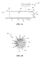
- FIG. 1A is a cross-sectional view of a filter assembly configured in accordance with an embodiment of the present technology.
- FIG. 1B is a top view of the filter assembly of FIG. 1A taken substantially along the line 1 B- 1 B.
- FIG. 2 is a block diagram illustrating a routine for loading and unloading a filtration system in accordance with an embodiment of the present technology.
- the present disclosure is directed toward fluid distribution filters having spiral filter media and associated systems and methods.
- several embodiments described below are directed toward filter assemblies that enhance the efficiency of filtration by distributing fluid across a filter media and providing a substantially equal fluid velocity through the filter assembly.
- the filter media can be loaded with a contaminant (e.g., sulfur) and/or compound thereof (e.g., calcium sulfate), and subsequently unloaded such that the filter media can be reused for additional filtration cycles and/or the contaminant can be repurposed for other applications.
- a contaminant e.g., sulfur
- compound thereof e.g., calcium sulfate
- the term “fluid” can include liquids, gases, plasmas, and/or solutions, some of which may include solid particles dispersed throughout the fluid.
- several embodiments described herein refer to filtering contaminants from a fluid.
- the term “contaminant” is to be construed broadly to refer to any substance being removed from a fluid by the filter media.
- FIGS. 1A-2 Certain details are set forth in the following description and in FIGS. 1A-2 to provide a thorough understanding of various embodiments of the disclosure. However, other details describing well-known structures and systems often associated with filters, filter media, and/or other aspects of filtration systems are not set forth below to avoid unnecessarily obscuring the description of various embodiments of the disclosure. Thus, it will be appreciated that several of the details set forth below are provided to describe the following embodiments in a manner sufficient to enable a person skilled in the relevant art to make and use the disclosed embodiments. Several of the details and advantages described below, however, may not be necessary to practice certain embodiments of the disclosure.
- FIG. 1A is a cross-sectional view of a filter assembly 100 configured in accordance with an embodiment of the present technology
- FIG. 1B is a top view of the filter assembly 100 of FIG. 1A taken substantially along the line of imaginary plane 1 B- 1 B.
- the filter assembly 100 can include a housing or canister 102 having a body portion 106 positioned between apertures or openings (identified individually as a first opening 104 a and a second opening 104 b , and referred to collectively as openings 104 ) at opposite end portions of the canister 102 .
- the first opening 104 a is part of a fitting 120 coupled to the canister 102 , but in other embodiments the first opening 104 a extends any suitable distance including directly through the canister 102 to distribute fluid through passageways defined by suitable extension into zone 106 of spiral distributor system 108 for flow 110 including portions 110 a , 110 b , 110 c , etc. Additionally, as shown in the illustrated embodiment, the first opening 104 a can have a smaller cross-sectional dimension (e.g., diameter) than the second opening 104 b . In other embodiments, the openings 104 can be equal in size or have different dimensions relative to one another.
- the first opening 104 a can be configured as an inlet through which unfiltered fluid enters the filter assembly 100
- the second opening 104 b can be configured as an outlet through which filtered fluid exits the filter assembly 100
- the inlet and the outlet can be reversed.
- the openings 104 can also be configured to serve as both the inlet and the outlet depending upon whether the filter assembly 100 is being loaded or unloaded with a contaminant.
- the canister 102 can be molded or otherwise formed from selected alloys by powder metallurgy, casting, cold heading, forging, or by injection molding or thermoforming from a polymer material. Polymer particles, such as polyfin particles made from recycled milk, juice, water, and/or other fluid containers, can be compression molded to form the shape of the canister 102 . In other embodiments, the canister 102 can be molded into two or more pieces that are subsequently joined by gluing, welding, and/or using suitable fastening methods known in the art. In other embodiments, the canister 102 can be formed from a transmissive material (e.g., glass or ceramic compositions) and/or other suitable materials.
- a transmissive material e.g., glass or ceramic compositions
- the body portion 106 of the canister 102 can house a filter media 108 that removes a contaminant from a fluid.
- the filter media 108 can be made from various filtration materials that remove contaminants from the fluid via physical barriers and/or chemical reactions, such as steel wool, micro-porous ceramics, materials loaded with calcium or magnesium, and/or other suitable filtration materials.
- the filter media 108 includes a structure made of plastic, silica, alumina, and/or other material that can be loaded with an element or compound, such as an activated carbon that can react with water to remove objectionable concentrations of sulfur or compounds containing sulfur, various phosphors, heavy metals such as lead or mercury, pathogens, and/or other contaminants from the water.
- the filter media 108 can be made from an architectural construct.
- Architectural constructs are synthetic matrix characterizations of crystals that are primarily comprised of graphene, graphite, boron nitride, and/or another suitable crystal. The configuration and the treatment of these crystals heavily influences the properties that the architectural construct will exhibit when it experiences certain conditions.
- architectural constructs can be manipulated to obtain the requisite surface tension to load almost any element or soluble to selectively filter a fluid. Additional features and characteristics of architectural constructs are described in U.S. patent application Ser. No. 13/027,214, filed Feb. 14, 2011, now issued as U.S. Pat. No. 8,980,416, and entitled “ARCHITECTURAL CONSTRUCT HAVING FOR EXAMPLE A PLURALITY OF ARCHITECTURAL CRYSTALS”; U.S. patent application Ser. No. 13/584,658, filed Aug. 13, 2012, and entitled “ARCHITECTURAL CONSTRUCT HAVING A PLURALITY OF IMPLEMENTATIONS”; and U.S. patent application Ser. No. 13/584,644, filed Aug. 13, 2012, now issued as U.S. Pat. No. 8,828,491, and entitled “METHODS FOR MANUFACTURING ARCHITECTURAL CONSTRUCTS”, each of which is incorporated herein by reference in its entirety.
- the filter assembly 100 can be configured to remove sulfur from potable water or a fluid fuel.
- Sulfur occurs naturally in various fluids and is introduced into fluids during various processes (e.g., thermochemical processes), but must typically be removed from the fluid before it is deemed suitable for use (e.g., as fuel, drinking water, etc.).
- Typical sulfur filters first remove sulfur from a fluid by forming hydrogen sulfide and subsequently dissociating the hydrogen sulfide (e.g., by electrolysis or adding heat) to separate the sulfur.
- the filter media 108 can react directly with the incoming fluid to remove the sulfur, thereby eliminating the intermediary step of forming hydrogen sulfide.
- the filter media 108 can include calcium and/or magnesium, and the sulfur can react therewith to form calcium sulfate and/or magnesium sulfate, respectively.
- the filter media 108 can include additional elements or compounds that react with the sulfur to filter it from the fluid.
- the filter assembly 100 can perform the intermediary step of forming hydrogen sulfide and disassociating the sulfur therefrom.
- the filter media 108 can also be configured to add pre-selected reagents or elements or compounds to the fluid during filtration.
- the filter media 108 can be loaded with a color and/or a flavor that is introduced into water as it moves through the filter assembly 100 .
- the filter media 108 can be loaded with various other elements or compounds that can be added to the fluid during filtration.
- the filter media 108 can be formed into one or more spiral-shaped distributor channels (identified individually as first-third channels 110 a - c , respectively, and referred to collectively as channels 110 ).
- the filter assembly 100 includes three channels 110 a - c spaced equally apart from one another, as shown by distances d 1 , d 2 , and d 3 .
- the filter assembly 100 can include one, two, or more than three channels 110 , and/or the channels 110 can be positioned varying distances apart from one another (i.e., d 1 , d 2 , and d 3 can differ in magnitude).
- the width of the channels 110 (labeled w 1 , w 2 , w 3 , respectively, in FIG. 1B ) can be varied such that the differently sized channels 110 receive fluids having different densities. Accordingly, the channels 110 themselves can be used to separate and filter the fluid as it enters the filter assembly 100 . This fluid separation provided by the varied depth or width channels can be used to separate blood during dialysis or other medical procedures. Additionally, the channels 110 can each include different filter media 108 to filter different contaminants from the fluid.
- the spiraled channels 110 can distribute the fluid entering the filter assembly 100 (e.g., via the first opening 104 a ) radially across the filter media 108 and provide substantially equal velocity through the channels 110 .
- the channels 110 can begin at a different distance from the opening 104 (e.g., varied depths into the body portion 106 of the canister 102 as measured from the first opening 104 a ) to lower the impedance toward the center of the spiral and thereby force the fluid outwardly toward the peripheral edge of the filter media 108 to provide essentially equal flow rates through zone 106 . This creates a more even flow distribution of the fluid across the filter media 108 and therefore increases the accessed surface area of the filter media 108 that participates in filtration of the fluid.
- the filter media 108 has a reduced likelihood that portions of the filter media 108 in the center will load or clog faster than peripheral portions of the filter media 108 .
- the spiraled channels 110 also create a substantially constant velocity of fluid flow axially along the length of the canister 102 . This inhibits the fluid from gathering in stagnant or dead zones where it is unable to be filtered and thus increases the efficiency of the filtration process.
- the sidewalls of the openings 104 can include threaded portions 118 configured to receive the fitting 120 having spiral features generally similar to the spiral-shaped filter media 108 to further increase fluid distribution across the filter media 108 and further enhance uniform fluid flow through the filter media 108 .
- the threaded portions 118 and/or other engagement features proximate to the openings 104 can also be used to connect with the filter assembly 100 to one or more extensions (not shown).
- the extensions can include filters having features similar to the filter assembly 100 and/or other filter configurations and functions.
- filter extensions increase the distance the fluid travels through the filter system (e.g., the filter assembly 100 and one or more filter extensions) and increases the dwell time of the fluid to enhance fluid filtration efficiency.
- filter extensions can be attached in series with the filter assembly 100 and used to filter various different contaminants from the fluid.
- the filter assembly 100 can be configured to filter a pre-selected contaminant from the fluid, and the next filter extension in the series can be configured to filter a different contaminant from the fluid.
- further extensions can be provided to add trace minerals to improve the taste and/or to provide specific health benefits.
- extensions can be attached to the end portions of the filter assembly 100 to transport fluid to and/or from locations.
- the filter assembly 100 can include a plurality of zones (identified individually as a first zone 112 , a second zone 114 and a third zone 116 ) that can individually include different filter media 108 .
- the zones 112 , 114 and 116 of the filter media 108 can be used to filter out progressively finer particles as the fluid moves from the inlet to the outlet.
- the filter media 108 in the first zone 112 can include a coarse, sand-packed filter media 108 to filter out larger particles (e.g., sand, sediment, etc.), and the filter media 108 in the third zone 116 can include a fine, micro-porous ceramic to filter out smaller particles.
- one or more of the zones 112 , 114 and 116 can include a filter media 108 having anti-microbial filtration components or characteristics (e.g., silver-coated activated carbon) to reduce or eliminate contaminations and/or biofouling in the filter assembly 100 and/or in subsequent processes.
- a filter media 108 having anti-microbial filtration components or characteristics (e.g., silver-coated activated carbon) to reduce or eliminate contaminations and/or biofouling in the filter assembly 100 and/or in subsequent processes.
- the filter assembly 100 can include and/or be operably coupled to a heat input or source 122 to facilitate the reaction between the filter media 108 and the contaminant.
- Heat from the heat source 122 can be transferred to the filter assembly 100 via infrared heating (e.g., from an engine), inductive heating, resistive heating, and/or other sources of heat.
- a renewable energy source such as solar power, wind power, hydro power, wave power, etc.
- heat source 122 can include other renewable and nonrenewable energy sources and other suitable heat generators.
- the fluid e.g., a fuel
- the fluid can be pre-heated (e.g., by the heat source 122 ) before it flows into the canister 102 to facilitate filtration reactions (e.g., sulfur with an iron donor or another carbon-loaded filter media 108 ), and the canister 102 can be insulated to reduce the total energy of the filtration process.
- the filter assembly 100 can also absorb and transfer heat away from permafrost to both cool the permafrost and facilitate the filtration reactions.
- the canister 102 can be made from a transmissive material (e.g., glass) to increase the transfer of radiant heat to or from the filter material 108 .
- the filter assembly 100 can host or perform an exothermic reaction in itself.
- the filter assembly 100 can therefore be configured to store the heat it generates (e.g., from filtration rations) and reuse it to facilitate further filtration reactions. In other embodiments, it may be desirable to remove heat from the filter assembly 100 during filtration.
- the heat produced and transferred away from the filter assembly 100 can be used in conjunction with other processes, such as those described in U.S. patent application Ser. No. 13/027,215, filed Feb. 14, 2011, now issued as U.S. Pat. No. 8,318,269, and entitled “INDUCTION FOR THERMOCHEMICAL PROCESSES, AND ASSOCIATED SYSTEMS AND METHODS”, and U.S. patent application Ser. No.
- the filter media 108 can conveniently be utilized as soil nutrients or safely discarded after its filtration capabilities have been exhausted.
- the filter media 108 can be disposed of with the canister 102 , or removed from the canister 102 and disposed such that the canister 102 can be reused with a new filter media.
- the canister 102 and/or the loaded filter media 108 can be recycled as a building material (e.g., a lightweight, fire-resistant honeycomb drywall) or in the construction of papercrete.
- the filtered contaminant can be repurposed and/or the filter media 108 can be reused.
- FIG. 2 is a block diagram illustrating a routine 200 for loading and unloading a filtration system in accordance with an embodiment of the present technology.
- the routine 200 can include receiving a fluid through an inlet of a filter assembly (block 210 ) and filtering a contaminant from the fluid using a filter media (block 220 ).
- the filter assembly can include features generally similar to the features of the filter assembly 100 described above with reference to FIGS. 1A and 1B .
- the filter assembly can include a canister housing a filter media made from an architectural construct, steel wool, micro-porous ceramic, calcium, and/or other suitable filter media.
- the filter media can be formed into even-flow distributors such as one or more spiral-shaped channels that distribute the fluid across the filter media to allow a greater surface area of the filter media to participate in filtration (i.e., not merely the inner portions of the filter media).
- the spiraled filter media can provide a substantially constant velocity of fluid flow axially along the length of the filter assembly that reduces the likelihood of stagnant zones and therefore enhances the efficiency of filtration.
- the contaminant or compound thereof can be unloaded from the filter media (block 230 ).
- the contaminant can be unloaded by selecting a fluid that will release the particular contaminant or compound thereof, running the fluid across the filter media, and collecting the contaminant in a reservoir.
- methane is filtered from a fluid and loaded onto the filter media.
- the methane can be removed from the filter media (e.g. activated carbon or zeolite) by flowing hydrogen or water (e.g. heated water or steam) across the filter media and releasing the purified methane.
- the filter media can be unloaded while it is still in the canister used during filtration. Accordingly, the configuration of the filter assembly can impart similar benefits to unloading the filter media that are loading the filter media during filtration. For example, because the filter media is configured in a spiral-like shape, the fluid is flushed over the filter media in a substantially uniform distribution and at a substantially equal velocity to enhance removal of the contaminant. In other embodiments, the loaded filter media can be removed from the canister before the contaminant is unloaded.
- the filter media can be used to filter a wide variety of feedstocks including for example, body fluids, water, wine, waste streams, and the like, for a variety of purposes, for example, to treat pathogenically suspect fluids such as those listed above with UV, ozone and or heat.
- the filter assembly can be used in pre-treatment processing or can be used in various combinations of post-treatment processing.
- multiple filter assemblies may be placed in series to sequentially remove contaminants or in parallel in a manifold arrangement to accommodate fluctuating or high volumes of feedstock flow.
- the unloaded contaminant can be repurposed in other applications (block 240 ). Purified methane, for example, can then be repurposed and used as fuel and/or other suitable functions. Iron sulfide (e.g., produced by filtering sulfur through steel wool media) can be unloaded for use during photosynthesis, and calcium sulfate (produced by filtering sulfur through a calcium-loaded media) can be unloaded for use as a nutrient for growing algae, vegetables, etc. In other embodiments, the unloaded contaminant can be reused for other suitable applications and purposes.
- Iron sulfide e.g., produced by filtering sulfur through steel wool media
- calcium sulfate produced by filtering sulfur through a calcium-loaded media
- the unloaded contaminant can be reused for other suitable applications and purposes.
- the filter media can be reused after the contaminant has been unloaded (block 250 ).
- the filter media can be made from carbon, silica, alumina, and/or other suitable materials that can be loaded with an element or compound for filtration, unloaded, and then reloaded with the same or a different element or compound for subsequent filtration cycles.
- the filter assembly 100 can have a different aspect ratio than that shown in FIG. 1A , such that the canister 102 is wider than it is long.
- Such a configuration may be of particular use to filter, for example, gaseous fluids.
- Certain aspects of the new technology described in the context of particular embodiments may be combined or eliminated in other embodiments.
- advantages associated with certain embodiments of the new technology have been described in the context of those embodiments, other embodiments may also exhibit such advantages, and not all embodiments need necessarily exhibit such advantages to fall within the scope of the technology. Accordingly, the disclosure and associated technology can encompass other embodiments not expressly shown or described herein.
Abstract
Description
Claims (12)
Priority Applications (1)
| Application Number | Priority Date | Filing Date | Title |
|---|---|---|---|
| US13/584,790 US9314719B2 (en) | 2011-08-12 | 2012-08-13 | Filter having spiral-shaped distributor channels |
Applications Claiming Priority (2)
| Application Number | Priority Date | Filing Date | Title |
|---|---|---|---|
| US201161523273P | 2011-08-12 | 2011-08-12 | |
| US13/584,790 US9314719B2 (en) | 2011-08-12 | 2012-08-13 | Filter having spiral-shaped distributor channels |
Publications (2)
| Publication Number | Publication Date |
|---|---|
| US20130206698A1 US20130206698A1 (en) | 2013-08-15 |
| US9314719B2 true US9314719B2 (en) | 2016-04-19 |
Family
ID=47715668
Family Applications (1)
| Application Number | Title | Priority Date | Filing Date |
|---|---|---|---|
| US13/584,790 Expired - Fee Related US9314719B2 (en) | 2011-08-12 | 2012-08-13 | Filter having spiral-shaped distributor channels |
Country Status (2)
| Country | Link |
|---|---|
| US (1) | US9314719B2 (en) |
| WO (1) | WO2013025654A2 (en) |
Cited By (4)
| Publication number | Priority date | Publication date | Assignee | Title |
|---|---|---|---|---|
| US20140044600A1 (en) * | 2011-08-12 | 2014-02-13 | Mcalister Technologies, Llc | Device for treating chemical compositions and methods for use thereof |
| US9511663B2 (en) | 2013-05-29 | 2016-12-06 | Mcalister Technologies, Llc | Methods for fuel tank recycling and net hydrogen fuel and carbon goods production along with associated apparatus and systems |
| US9534296B2 (en) | 2013-03-15 | 2017-01-03 | Mcalister Technologies, Llc | Methods of manufacture of engineered materials and devices |
| US10807295B2 (en) * | 2015-02-19 | 2020-10-20 | Next Generation Analytics Gmbh | Filter device and filter method |
Families Citing this family (6)
| Publication number | Priority date | Publication date | Assignee | Title |
|---|---|---|---|---|
| US8147599B2 (en) | 2009-02-17 | 2012-04-03 | Mcalister Technologies, Llc | Apparatuses and methods for storing and/or filtering a substance |
| WO2013025643A2 (en) | 2011-08-12 | 2013-02-21 | Mcalister Technologies, Llc | Dynamic filtration system and associated methods |
| WO2015016550A1 (en) | 2013-07-29 | 2015-02-05 | Lg Electronics Inc. | Method for calculating and reporting a buffer status and device therefor |
| CN105091130A (en) * | 2015-09-25 | 2015-11-25 | 江苏创兰太阳能空调有限公司 | Window air conditioner |
| CN109354213A (en) * | 2018-10-31 | 2019-02-19 | 浙江省农业科学院 | The biofilter water distribution system of water distribution uniformity |
| CN114100228B (en) * | 2022-01-24 | 2022-10-21 | 山西炬华新材料科技有限公司 | Preparation method and equipment of ultra-large-pore pseudo-boehmite powder |
Citations (124)
| Publication number | Priority date | Publication date | Assignee | Title |
|---|---|---|---|---|
| US1753809A (en) * | 1926-07-28 | 1930-04-08 | Gen Motors Res Corp | Oil filter |
| US3404061A (en) | 1962-03-21 | 1968-10-01 | Union Carbide Corp | Flexible graphite material of expanded particles compressed together |
| US3830204A (en) | 1972-03-07 | 1974-08-20 | Alister R Mc | Fuel injection-spark ignition system for an internal combustion engine |
| US3935354A (en) | 1970-08-21 | 1976-01-27 | Olcott Eugene L | Shaped articles of pyrolytic graphite-silicon carbide microcomposites |
| US3967256A (en) | 1973-04-26 | 1976-06-29 | Marine And Industrial Developments Limited | Integrity monitoring system for storage tank insulation |
| US4066046A (en) | 1974-07-29 | 1978-01-03 | Mcalister Roy E | Method and apparatus for fuel injection-spark ignition system for an internal combustion engine |
| US4077788A (en) | 1976-04-13 | 1978-03-07 | The United States Of America Asthe Administrator Of The National Aeronautics And Space Administration | Atomic hydrogen storage method and apparatus |
| US4094762A (en) | 1974-11-05 | 1978-06-13 | United Kingdom Atomic Energy Authority | Method for the storage of material |
| US4193827A (en) | 1976-04-13 | 1980-03-18 | The United States Of America As Represented By The Administrator Of The National Aeronautics And Space Administration | Atomic hydrogen storage |
| US4210103A (en) | 1977-04-04 | 1980-07-01 | Southwest Research Institute | Fuel system for and a method of operating a spark-ignited internal combustion engine |
| EP0025858B1 (en) | 1979-09-18 | 1983-06-08 | International Business Machines Corporation | Rechargeable storage means for binding gaseous hydrogen |
| US4407238A (en) | 1981-10-26 | 1983-10-04 | Conoco Inc. | Methanol dissociation using a copper-chromium-manganese catalyst |
| US4472275A (en) | 1981-12-30 | 1984-09-18 | Daidotokushuko Kabushikikaisha | Magnetic separator |
| US4495074A (en) | 1981-08-20 | 1985-01-22 | Unitika, Ltd. | Method and apparatus for filtration using ferromagnetic metal fibers |
| US4567857A (en) | 1980-02-26 | 1986-02-04 | The United States Of America As Represented By The Administrator Of The National Aeronautics And Space Administration | Combustion engine system |
| EP0056717B1 (en) | 1981-01-16 | 1986-04-09 | Inoue-Japax Research Incorporated | Magnetic filtration apparatus |
| US4588106A (en) | 1983-12-05 | 1986-05-13 | Stark Sr Robert G | Fiberglass molded pressure vessel and method of making same |
| US4600529A (en) | 1983-09-19 | 1986-07-15 | Gas Research Institute | Dehydrogenation of alcohols using alkali carbonate catalysts |
| US4676972A (en) | 1985-07-29 | 1987-06-30 | The Standard Oil Company | Process for the conversion of alcohols to gaseous products |
| US4696742A (en) * | 1983-12-22 | 1987-09-29 | Toho Beslon Co., Ltd. | Active carbon fibers and filter adsorption unit for water purification comprising said fibers |
| US5017317A (en) | 1989-12-04 | 1991-05-21 | Board Of Regents, The Uni. Of Texas System | Gas phase selective beam deposition |
| US5067447A (en) | 1988-07-26 | 1991-11-26 | Kabushiki Kaisha Toyoda Jidoshokki Seisakusho | Method for controlling heat of a metal hydride container |
| US5220080A (en) | 1992-06-29 | 1993-06-15 | Sun Company, Inc. (R&M) | Chromia on metal oxide catalysts for the oxidation of methane to methanol |
| WO1993012867A1 (en) | 1991-12-20 | 1993-07-08 | Ceramem Separations Limited Partnership | Catalytic filtration device and method |
| US5284996A (en) | 1992-02-28 | 1994-02-08 | Mcdonnell Douglas Corporation | Waste gas storage |
| US5298046A (en) * | 1993-01-06 | 1994-03-29 | Minnesota Mining And Manufacturing Company | Diesel particulate filter element and filter |
| US5343699A (en) | 1989-06-12 | 1994-09-06 | Mcalister Roy E | Method and apparatus for improved operation of internal combustion engines |
| WO1996041745A1 (en) | 1995-06-09 | 1996-12-27 | Zvi Horovitz | High bulk density, parallel carbon fibers |
| US5618501A (en) | 1992-12-09 | 1997-04-08 | Emitec, Gesellschaft Fuer Emissionstechnologie Mbh | Catalytic converter with two or more honeycomb bodies in a casing tube and method for its production |
| US5639707A (en) | 1992-05-05 | 1997-06-17 | Ucar Carbon Technology Corporation | Process for the storage of methane with activated carbon |
| US5648184A (en) | 1995-04-13 | 1997-07-15 | Toyo Boseki Kabushiki Kaisha | Electrode material for flow-through type electrolytic cell, wherein the electrode comprises carbonaceous material having at least one groove |
| US5683547A (en) | 1990-11-21 | 1997-11-04 | Hitachi, Ltd. | Processing method and apparatus using focused energy beam |
| US5731046A (en) | 1994-01-18 | 1998-03-24 | Qqc, Inc. | Fabrication of diamond and diamond-like carbon coatings |
| US5772938A (en) | 1996-05-10 | 1998-06-30 | Sharp; Bruce R. | Composite storage tank having double wall characteristics |
| US5822838A (en) | 1996-02-01 | 1998-10-20 | Lockheed Martin Corporation | High performance, thin metal lined, composite overwrapped pressure vessel |
| US5829418A (en) | 1996-04-24 | 1998-11-03 | Honda Giken Kogyo Kabushiki Kaisha | Fuel supply system for internal combustion engines |
| US5916531A (en) * | 1997-04-29 | 1999-06-29 | Pan; Chuen Yong | Spiral fixed-bed module for adsorber and catalytic reactor |
| WO1999035297A1 (en) | 1998-01-02 | 1999-07-15 | Dana Corporation | Laser phase transformation and ion implantation in metals |
| US6015065A (en) | 1997-08-29 | 2000-01-18 | Mcalister; Roy E. | Compact fluid storage system |
| US6015041A (en) | 1996-04-01 | 2000-01-18 | Westinghouse Savannah River Company | Apparatus and methods for storing and releasing hydrogen |
| US6155212A (en) | 1989-06-12 | 2000-12-05 | Mcalister; Roy E. | Method and apparatus for operation of combustion engines |
| EP1108588A2 (en) | 1999-12-18 | 2001-06-20 | Delphi Technologies, Inc. | Fuel permeation barrier fuel tank |
| US6306198B1 (en) | 1997-06-04 | 2001-10-23 | David Richard Corbin | Method of separating and selectively removing hydrogen contaminant from hydrogen-containing process streams and compositions useful therefor |
| JP2002128501A (en) | 2000-10-18 | 2002-05-09 | Sony Corp | Method for gas storage and fuel cell |
| US6432176B1 (en) | 1998-12-15 | 2002-08-13 | Mannesmann Ag | Device for storing compressed gas |
| US20020112479A1 (en) | 2001-01-09 | 2002-08-22 | Keefer Bowie G. | Power plant with energy recovery from fuel storage |
| US20020122972A1 (en) | 1999-05-06 | 2002-09-05 | Tom Klitsner | Fuel cell and membrane |
| US6466597B1 (en) | 1998-06-17 | 2002-10-15 | Matsushita Electric Industrial Co., Ltd. | Semiconductor laser device |
| EP1256369A2 (en) | 2001-05-08 | 2002-11-13 | Fleetguard, Inc. | Dual section exhaust aftertreatment filter and method |
| US6503584B1 (en) | 1997-08-29 | 2003-01-07 | Mcalister Roy E. | Compact fluid storage system |
| US20030037674A1 (en) | 2001-08-23 | 2003-02-27 | Allie Mark C. | Regenerable filter with localized and efficient heating |
| US6591857B2 (en) | 2001-11-29 | 2003-07-15 | Visteon Global Technologies, Inc. | Fuel tank venting system |
| US20030170389A1 (en) | 2002-03-05 | 2003-09-11 | Sandhu Gurtej S. | Atomic layer deposition with point of use generated reactive gas species |
| US20030167923A1 (en) | 2000-05-10 | 2003-09-11 | Frank Grote | Tank for the reversible storage of hydrogen |
| WO2003078252A2 (en) | 2002-03-15 | 2003-09-25 | Fuelsell Technologies, Inc. | Method and apparatus for a hydrogen fuel cassette distribution and recovery system |
| US6626981B2 (en) | 2000-07-07 | 2003-09-30 | Advanced Fuel Research, Inc. | Microporous carbons for gas storage |
| US20030209149A1 (en) | 2002-05-09 | 2003-11-13 | Vitaliy Myasnikov | Honeycomb hydrogen storage structure |
| US6660063B2 (en) | 1998-03-27 | 2003-12-09 | Advanced Technology Materials, Inc | Sorbent-based gas storage and delivery system |
| WO2004016982A2 (en) | 2002-08-14 | 2004-02-26 | Texaco Ovonic Hydrogen Systems Llc | Onboard hydrogen storage unit with heat transfer system for use in a hydrogen powered vehicle |
| US6709497B2 (en) | 2002-05-09 | 2004-03-23 | Texaco Ovonic Hydrogen Systems Llc | Honeycomb hydrogen storage structure |
| WO2004024845A2 (en) | 2002-09-10 | 2004-03-25 | Fuelsell Technologies, Inc. | Hydrogen storage, distribution, and recovery system |
| US20040076561A1 (en) | 2000-05-23 | 2004-04-22 | Hisashi Kajiura | Method for producing hydrogen storage material and hydrogen storing and desorbing apparatus |
| US6743278B1 (en) | 2002-12-10 | 2004-06-01 | Advanced Technology Materials, Inc. | Gas storage and dispensing system with monolithic carbon adsorbent |
| WO2004050798A2 (en) | 2002-12-04 | 2004-06-17 | Fuelsell Technologies, Inc. | Hydrogen storage, distribution, and recovery system |
| US6756140B1 (en) | 1989-06-12 | 2004-06-29 | Mcalister Roy E. | Energy conversion system |
| US20040200460A1 (en) | 2003-03-10 | 2004-10-14 | Mitsubishi Denki Kabushiki Kaisha | Apparatus for detecting fuel-vapor gas leaks, and vent valve apparatus applied to this apparatus |
| WO2004108590A2 (en) | 2002-07-10 | 2004-12-16 | Fuelsell Technologies, Inc. | Improved methods for hydrogen storage using doped alanate compositions |
| US6834508B2 (en) | 2002-08-29 | 2004-12-28 | Nanomix, Inc. | Hydrogen storage and supply system |
| US6840264B1 (en) | 2003-08-13 | 2005-01-11 | Visteon Global Technologies, Inc. | Fuel tank venting system for reduced fuel permeation |
| US20050148466A1 (en) | 2003-12-29 | 2005-07-07 | Lemmon John P. | Compositions and methods for hydrogen storage and recovery |
| US6918382B2 (en) | 2002-08-26 | 2005-07-19 | Energy Conversion Devices, Inc. | Hydrogen powered scooter |
| US20050178365A1 (en) | 2002-05-29 | 2005-08-18 | John Washeleski | Vehicle fuel management system |
| JP2006035174A (en) | 2004-07-29 | 2006-02-09 | Toyota Motor Corp | Hydrogen occlusion material and manufacture and utilization of the same |
| US20060048808A1 (en) | 2004-09-09 | 2006-03-09 | Ruckman Jack H | Solar, catalytic, hydrogen generation apparatus and method |
| US20060088739A1 (en) | 2004-10-26 | 2006-04-27 | Energy Conversion Devices, Inc. | Power generation and supply system |
| US7048839B2 (en) | 2002-01-29 | 2006-05-23 | Mitsubishi Corporation | System and method for generating high pressure hydrogen |
| US20060151382A1 (en) * | 2005-01-12 | 2006-07-13 | Petrik Viktor I | Contact devices with nanostructured materials |
| US7097748B2 (en) | 2002-04-23 | 2006-08-29 | University Of Massachusetts | Electrolyzer pressure equalization system |
| US7112239B2 (en) | 2003-05-20 | 2006-09-26 | Toyota Jidosha Kabushiki Kaisha | Gas storage apparatus |
| WO2006112919A2 (en) | 2005-04-12 | 2006-10-26 | General Electric Company | Electrochemical cell structure |
| US7160361B2 (en) * | 2003-10-15 | 2007-01-09 | Delphi Technologies, Inc. | Evaporative emission treatment device |
| US7169214B2 (en) | 2003-01-24 | 2007-01-30 | Kabushiki Kaisha Toyota Jidoshokki | High pressure tank |
| US7172645B1 (en) | 2003-06-30 | 2007-02-06 | Sun Microsystems, Inc. | Gas filtration and storage using activated carbon/graphite foam monoliths |
| JP2007077265A (en) | 2005-09-14 | 2007-03-29 | Nippon Oil Corp | Porous substance and its production method |
| US7241331B2 (en) | 2003-11-18 | 2007-07-10 | Industrial Technology Research Institute | Metal hydride canister apparatus |
| US7306862B2 (en) | 2001-05-23 | 2007-12-11 | Forschungszentrum Karlsruhe Gmbh | Removable storage method for hydrogen and hydrogen reservoir |
| US7320726B2 (en) | 2004-12-31 | 2008-01-22 | Chih-Kang Shih | Hydrogen storage apparatus |
| US7323043B2 (en) | 2003-07-28 | 2008-01-29 | Deere & Company | Storage container associated with a thermal energy management system |
| US7325401B1 (en) | 2004-04-13 | 2008-02-05 | Brayton Energy, Llc | Power conversion systems |
| US7331178B2 (en) | 2003-01-21 | 2008-02-19 | Los Angeles Advisory Services Inc | Hybrid generation with alternative fuel sources |
| US20080142377A1 (en) | 2006-12-19 | 2008-06-19 | Honda Motor Co., Ltd. | Gas storage container |
| US7399325B1 (en) | 2002-03-15 | 2008-07-15 | Fuelsell Technologies, Inc. | Method and apparatus for a hydrogen fuel cassette distribution and recovery system |
| US20080190943A1 (en) | 2007-02-08 | 2008-08-14 | Demaria Joseph | Attaching a component to an internal surface of a tank formed of polymer |
| US20080203101A1 (en) | 2003-03-25 | 2008-08-28 | Toyota Jidosha Kabushiki Kaisha | Gas storage tank and method of manufacturing the same |
| US20080226532A1 (en) | 2006-10-27 | 2008-09-18 | Zhigang Zak-Fang | Light metal based material system for hydrogen storage |
| US7431756B2 (en) | 2002-05-09 | 2008-10-07 | Ovonic Hydrogen Systems Llc | Modular metal hydride hydrogen storage system |
| US7455723B2 (en) | 2005-12-22 | 2008-11-25 | Modine Manufacturing Company | Hydrogen storage and release device |
| US20090014062A1 (en) | 2004-01-22 | 2009-01-15 | Showa Denko K.K. | Metal Oxide Dispersion, Metal Oxide Electrode Film, and Dye Sensitized Solar Cell |
| US7494530B2 (en) | 2002-12-10 | 2009-02-24 | Advanced Technology Materials, Inc. | Gas storage and dispensing system with monolithic carbon adsorbent |
| US20090104496A1 (en) | 2005-07-15 | 2009-04-23 | Gen-X Power Corp | Methanol Fuel Cells |
| US20090214800A1 (en) | 2008-02-08 | 2009-08-27 | Kimitsugu Saito | Apparatus for and method of forming carbon nanotube |
| US20090229555A1 (en) | 2004-04-21 | 2009-09-17 | Angstore Technologies Ltd. | Storage Systems For Adsorbable Gaseous Fuel And Methods Of Producing The Same |
| US7594939B2 (en) | 2004-09-01 | 2009-09-29 | Hyogen, Ltd. | System for hydrogen storage and generation |
| US20100047633A1 (en) | 2008-01-02 | 2010-02-25 | Aharon Brandstetter | Electric Storage Fuel Cell System and Method |
| US7727492B2 (en) | 2006-06-14 | 2010-06-01 | Ovonic Hydrogen Systems Llc | Apparatus for refueling on-board metal hydride hydrogen storage tank |
| US7744127B2 (en) | 2006-09-29 | 2010-06-29 | Gm Global Technology Operations, Inc. | Fuel tank mount |
| US7771512B2 (en) | 2005-06-24 | 2010-08-10 | Washington State University Research Foundation | Apparatus with high surface area nanostructures for hydrogen storage, and methods of storing hydrogen |
| US7780747B2 (en) | 2003-10-14 | 2010-08-24 | Advanced Technology Materials, Inc. | Apparatus and method for hydrogen generation from gaseous hydride |
| US20110041519A1 (en) | 2009-02-17 | 2011-02-24 | Mcalister Technologies, Llc | Apparatuses and methods for storing and/or filtering a substance |
| US7896190B2 (en) | 2006-07-17 | 2011-03-01 | GM Global Technology Operations LLC | Composites having an improved resistance to fatigue |
| US7911071B2 (en) | 2007-11-06 | 2011-03-22 | Devine Timothy J | Systems and methods for producing, shipping, distributing, and storing hydrogen |
| US8002880B2 (en) | 2002-12-10 | 2011-08-23 | Advanced Technology Materials, Inc. | Gas storage and dispensing system with monolithic carbon adsorbent |
| US20120003518A1 (en) | 2009-06-26 | 2012-01-05 | Halbert Fischel | Galvanic electrochemical cells utilizing taylor vortex flows |
| KR20120010420A (en) | 2010-07-26 | 2012-02-03 | 서강대학교산학협력단 | Polymer electrolyte having chemically bonded phosphoric acid group, prepariong method of the same, and membrane electrode assembly and fuel cell using the same |
| US20120048195A1 (en) | 2010-09-01 | 2012-03-01 | Jaw Tian Lin | Method for mass production of graphene and carbon tubes by deposition of carbon atoms, on flat surfaces and inside walls of tubes, generated from dissociation of a carbon-containing gas stimulated by a tunable high power pulsed laser |
| US20120156578A1 (en) | 2010-03-31 | 2012-06-21 | Panasonic Corporation | Photoelectrochemical cell and energy system using same |
| US8318269B2 (en) | 2009-02-17 | 2012-11-27 | Mcalister Technologies, Llc | Induction for thermochemical processes, and associated systems and methods |
| US20130101808A1 (en) | 2011-08-12 | 2013-04-25 | Mcalister Technologies, Llc | Architectural construct having a plurality of implementations |
| US20130224614A1 (en) | 2012-02-27 | 2013-08-29 | Ardica Technologies, Inc. | Field-enhanced thermal decomposition of fuel storage compositions |
| US8617399B2 (en) | 2011-08-12 | 2013-12-31 | Mcalister Technologies, Llc | Dynamic filtration system and associated methods |
| US20140272640A1 (en) | 2013-03-15 | 2014-09-18 | Mcalister Technologies, Llc | Multifunctional electrochemical devices |
| US20140272195A1 (en) | 2013-03-15 | 2014-09-18 | Mcalister Technologies, Llc | Methods of manufacture of engineered materials and devices |
| US8898416B2 (en) | 2006-06-14 | 2014-11-25 | International Business Machines Corporation | Storage allocation management in switches utilizing flow control |
| US9079489B2 (en) | 2013-05-29 | 2015-07-14 | Mcalister Technologies, Llc | Methods for fuel tank recycling and net hydrogen fuel and carbon goods production along with associated apparatus and systems |
-
2012
- 2012-08-13 US US13/584,790 patent/US9314719B2/en not_active Expired - Fee Related
- 2012-08-13 WO PCT/US2012/050665 patent/WO2013025654A2/en active Application Filing
Patent Citations (143)
| Publication number | Priority date | Publication date | Assignee | Title |
|---|---|---|---|---|
| US1753809A (en) * | 1926-07-28 | 1930-04-08 | Gen Motors Res Corp | Oil filter |
| US3404061A (en) | 1962-03-21 | 1968-10-01 | Union Carbide Corp | Flexible graphite material of expanded particles compressed together |
| US3935354A (en) | 1970-08-21 | 1976-01-27 | Olcott Eugene L | Shaped articles of pyrolytic graphite-silicon carbide microcomposites |
| US3830204A (en) | 1972-03-07 | 1974-08-20 | Alister R Mc | Fuel injection-spark ignition system for an internal combustion engine |
| US3967256A (en) | 1973-04-26 | 1976-06-29 | Marine And Industrial Developments Limited | Integrity monitoring system for storage tank insulation |
| US4066046A (en) | 1974-07-29 | 1978-01-03 | Mcalister Roy E | Method and apparatus for fuel injection-spark ignition system for an internal combustion engine |
| US4094762A (en) | 1974-11-05 | 1978-06-13 | United Kingdom Atomic Energy Authority | Method for the storage of material |
| US4077788A (en) | 1976-04-13 | 1978-03-07 | The United States Of America Asthe Administrator Of The National Aeronautics And Space Administration | Atomic hydrogen storage method and apparatus |
| US4193827A (en) | 1976-04-13 | 1980-03-18 | The United States Of America As Represented By The Administrator Of The National Aeronautics And Space Administration | Atomic hydrogen storage |
| US4210103A (en) | 1977-04-04 | 1980-07-01 | Southwest Research Institute | Fuel system for and a method of operating a spark-ignited internal combustion engine |
| EP0025858B1 (en) | 1979-09-18 | 1983-06-08 | International Business Machines Corporation | Rechargeable storage means for binding gaseous hydrogen |
| US4567857A (en) | 1980-02-26 | 1986-02-04 | The United States Of America As Represented By The Administrator Of The National Aeronautics And Space Administration | Combustion engine system |
| EP0056717B1 (en) | 1981-01-16 | 1986-04-09 | Inoue-Japax Research Incorporated | Magnetic filtration apparatus |
| US4495074A (en) | 1981-08-20 | 1985-01-22 | Unitika, Ltd. | Method and apparatus for filtration using ferromagnetic metal fibers |
| US4407238A (en) | 1981-10-26 | 1983-10-04 | Conoco Inc. | Methanol dissociation using a copper-chromium-manganese catalyst |
| US4472275A (en) | 1981-12-30 | 1984-09-18 | Daidotokushuko Kabushikikaisha | Magnetic separator |
| US4600529A (en) | 1983-09-19 | 1986-07-15 | Gas Research Institute | Dehydrogenation of alcohols using alkali carbonate catalysts |
| US4588106A (en) | 1983-12-05 | 1986-05-13 | Stark Sr Robert G | Fiberglass molded pressure vessel and method of making same |
| US4696742A (en) * | 1983-12-22 | 1987-09-29 | Toho Beslon Co., Ltd. | Active carbon fibers and filter adsorption unit for water purification comprising said fibers |
| US4676972A (en) | 1985-07-29 | 1987-06-30 | The Standard Oil Company | Process for the conversion of alcohols to gaseous products |
| US5067447A (en) | 1988-07-26 | 1991-11-26 | Kabushiki Kaisha Toyoda Jidoshokki Seisakusho | Method for controlling heat of a metal hydride container |
| US6155212A (en) | 1989-06-12 | 2000-12-05 | Mcalister; Roy E. | Method and apparatus for operation of combustion engines |
| US6756140B1 (en) | 1989-06-12 | 2004-06-29 | Mcalister Roy E. | Energy conversion system |
| US5343699A (en) | 1989-06-12 | 1994-09-06 | Mcalister Roy E | Method and apparatus for improved operation of internal combustion engines |
| US5017317A (en) | 1989-12-04 | 1991-05-21 | Board Of Regents, The Uni. Of Texas System | Gas phase selective beam deposition |
| US5683547A (en) | 1990-11-21 | 1997-11-04 | Hitachi, Ltd. | Processing method and apparatus using focused energy beam |
| WO1993012867A1 (en) | 1991-12-20 | 1993-07-08 | Ceramem Separations Limited Partnership | Catalytic filtration device and method |
| US5284996A (en) | 1992-02-28 | 1994-02-08 | Mcdonnell Douglas Corporation | Waste gas storage |
| US5639707A (en) | 1992-05-05 | 1997-06-17 | Ucar Carbon Technology Corporation | Process for the storage of methane with activated carbon |
| US5220080A (en) | 1992-06-29 | 1993-06-15 | Sun Company, Inc. (R&M) | Chromia on metal oxide catalysts for the oxidation of methane to methanol |
| US5618501A (en) | 1992-12-09 | 1997-04-08 | Emitec, Gesellschaft Fuer Emissionstechnologie Mbh | Catalytic converter with two or more honeycomb bodies in a casing tube and method for its production |
| US5298046A (en) * | 1993-01-06 | 1994-03-29 | Minnesota Mining And Manufacturing Company | Diesel particulate filter element and filter |
| US5731046A (en) | 1994-01-18 | 1998-03-24 | Qqc, Inc. | Fabrication of diamond and diamond-like carbon coatings |
| US5648184A (en) | 1995-04-13 | 1997-07-15 | Toyo Boseki Kabushiki Kaisha | Electrode material for flow-through type electrolytic cell, wherein the electrode comprises carbonaceous material having at least one groove |
| WO1996041745A1 (en) | 1995-06-09 | 1996-12-27 | Zvi Horovitz | High bulk density, parallel carbon fibers |
| US5822838A (en) | 1996-02-01 | 1998-10-20 | Lockheed Martin Corporation | High performance, thin metal lined, composite overwrapped pressure vessel |
| US6015041A (en) | 1996-04-01 | 2000-01-18 | Westinghouse Savannah River Company | Apparatus and methods for storing and releasing hydrogen |
| US5829418A (en) | 1996-04-24 | 1998-11-03 | Honda Giken Kogyo Kabushiki Kaisha | Fuel supply system for internal combustion engines |
| US5772938A (en) | 1996-05-10 | 1998-06-30 | Sharp; Bruce R. | Composite storage tank having double wall characteristics |
| US5916531A (en) * | 1997-04-29 | 1999-06-29 | Pan; Chuen Yong | Spiral fixed-bed module for adsorber and catalytic reactor |
| US6306198B1 (en) | 1997-06-04 | 2001-10-23 | David Richard Corbin | Method of separating and selectively removing hydrogen contaminant from hydrogen-containing process streams and compositions useful therefor |
| US6015065A (en) | 1997-08-29 | 2000-01-18 | Mcalister; Roy E. | Compact fluid storage system |
| US6503584B1 (en) | 1997-08-29 | 2003-01-07 | Mcalister Roy E. | Compact fluid storage system |
| WO1999035297A1 (en) | 1998-01-02 | 1999-07-15 | Dana Corporation | Laser phase transformation and ion implantation in metals |
| US6660063B2 (en) | 1998-03-27 | 2003-12-09 | Advanced Technology Materials, Inc | Sorbent-based gas storage and delivery system |
| US6466597B1 (en) | 1998-06-17 | 2002-10-15 | Matsushita Electric Industrial Co., Ltd. | Semiconductor laser device |
| US6432176B1 (en) | 1998-12-15 | 2002-08-13 | Mannesmann Ag | Device for storing compressed gas |
| US20020122972A1 (en) | 1999-05-06 | 2002-09-05 | Tom Klitsner | Fuel cell and membrane |
| EP1108588A2 (en) | 1999-12-18 | 2001-06-20 | Delphi Technologies, Inc. | Fuel permeation barrier fuel tank |
| US20030167923A1 (en) | 2000-05-10 | 2003-09-11 | Frank Grote | Tank for the reversible storage of hydrogen |
| US20040076561A1 (en) | 2000-05-23 | 2004-04-22 | Hisashi Kajiura | Method for producing hydrogen storage material and hydrogen storing and desorbing apparatus |
| US6626981B2 (en) | 2000-07-07 | 2003-09-30 | Advanced Fuel Research, Inc. | Microporous carbons for gas storage |
| JP2002128501A (en) | 2000-10-18 | 2002-05-09 | Sony Corp | Method for gas storage and fuel cell |
| WO2002056400A3 (en) | 2001-01-09 | 2002-10-24 | Questair Technologies Inc. | Fuel cell power plant with energy recovery from fuel storage |
| US8015808B2 (en) | 2001-01-09 | 2011-09-13 | G4 Insights Inc. | Power plant with energy recovery from fuel storage |
| US20020112479A1 (en) | 2001-01-09 | 2002-08-22 | Keefer Bowie G. | Power plant with energy recovery from fuel storage |
| EP1256369A2 (en) | 2001-05-08 | 2002-11-13 | Fleetguard, Inc. | Dual section exhaust aftertreatment filter and method |
| US7306862B2 (en) | 2001-05-23 | 2007-12-11 | Forschungszentrum Karlsruhe Gmbh | Removable storage method for hydrogen and hydrogen reservoir |
| US20030037674A1 (en) | 2001-08-23 | 2003-02-27 | Allie Mark C. | Regenerable filter with localized and efficient heating |
| US6591857B2 (en) | 2001-11-29 | 2003-07-15 | Visteon Global Technologies, Inc. | Fuel tank venting system |
| US7048839B2 (en) | 2002-01-29 | 2006-05-23 | Mitsubishi Corporation | System and method for generating high pressure hydrogen |
| US20030170389A1 (en) | 2002-03-05 | 2003-09-11 | Sandhu Gurtej S. | Atomic layer deposition with point of use generated reactive gas species |
| US20040185184A1 (en) | 2002-03-05 | 2004-09-23 | Sandhu Gurtej S. | Atomic layer deposition with point of use generated reactive gas species |
| US8066946B2 (en) | 2002-03-15 | 2011-11-29 | Redmond Scott D | Hydrogen storage, distribution, and recovery system |
| US7169489B2 (en) | 2002-03-15 | 2007-01-30 | Fuelsell Technologies, Inc. | Hydrogen storage, distribution, and recovery system |
| US7399325B1 (en) | 2002-03-15 | 2008-07-15 | Fuelsell Technologies, Inc. | Method and apparatus for a hydrogen fuel cassette distribution and recovery system |
| WO2003078252A2 (en) | 2002-03-15 | 2003-09-25 | Fuelsell Technologies, Inc. | Method and apparatus for a hydrogen fuel cassette distribution and recovery system |
| US7097748B2 (en) | 2002-04-23 | 2006-08-29 | University Of Massachusetts | Electrolyzer pressure equalization system |
| US6709497B2 (en) | 2002-05-09 | 2004-03-23 | Texaco Ovonic Hydrogen Systems Llc | Honeycomb hydrogen storage structure |
| US7431756B2 (en) | 2002-05-09 | 2008-10-07 | Ovonic Hydrogen Systems Llc | Modular metal hydride hydrogen storage system |
| US20030209149A1 (en) | 2002-05-09 | 2003-11-13 | Vitaliy Myasnikov | Honeycomb hydrogen storage structure |
| US20050178365A1 (en) | 2002-05-29 | 2005-08-18 | John Washeleski | Vehicle fuel management system |
| WO2004108590A2 (en) | 2002-07-10 | 2004-12-16 | Fuelsell Technologies, Inc. | Improved methods for hydrogen storage using doped alanate compositions |
| US7011768B2 (en) | 2002-07-10 | 2006-03-14 | Fuelsell Technologies, Inc. | Methods for hydrogen storage using doped alanate compositions |
| US7363965B2 (en) | 2002-08-14 | 2008-04-29 | Ovonic Hydrogen Systems Llc | Onboard hydrogen storage unit with heat transfer system for use in a hydrogen powered vehicle |
| US6860923B2 (en) | 2002-08-14 | 2005-03-01 | Texaco Ovonic Hydrogen Systems Llc | Onboard hydrogen storage unit with heat transfer system for use in a hydrogen powered vehicle |
| US6918430B2 (en) | 2002-08-14 | 2005-07-19 | Texaco Ovonic Hydrogen Systems Llc | Onboard hydrogen storage unit with heat transfer system for use in a hydrogen powered vehicle |
| WO2004016982A2 (en) | 2002-08-14 | 2004-02-26 | Texaco Ovonic Hydrogen Systems Llc | Onboard hydrogen storage unit with heat transfer system for use in a hydrogen powered vehicle |
| US6918382B2 (en) | 2002-08-26 | 2005-07-19 | Energy Conversion Devices, Inc. | Hydrogen powered scooter |
| US6834508B2 (en) | 2002-08-29 | 2004-12-28 | Nanomix, Inc. | Hydrogen storage and supply system |
| WO2004024845A2 (en) | 2002-09-10 | 2004-03-25 | Fuelsell Technologies, Inc. | Hydrogen storage, distribution, and recovery system |
| WO2004050798A2 (en) | 2002-12-04 | 2004-06-17 | Fuelsell Technologies, Inc. | Hydrogen storage, distribution, and recovery system |
| US7455719B2 (en) | 2002-12-10 | 2008-11-25 | Advanced Technology Materials, Inc. | Gas storage and dispensing system with monolithic carbon adsorbent |
| US6743278B1 (en) | 2002-12-10 | 2004-06-01 | Advanced Technology Materials, Inc. | Gas storage and dispensing system with monolithic carbon adsorbent |
| US8002880B2 (en) | 2002-12-10 | 2011-08-23 | Advanced Technology Materials, Inc. | Gas storage and dispensing system with monolithic carbon adsorbent |
| US6939394B2 (en) | 2002-12-10 | 2005-09-06 | Advanced Technology Materials, Inc. | Gas storage and dispensing system with monolithic carbon adsorbent |
| US7494530B2 (en) | 2002-12-10 | 2009-02-24 | Advanced Technology Materials, Inc. | Gas storage and dispensing system with monolithic carbon adsorbent |
| WO2004053383A2 (en) | 2002-12-10 | 2004-06-24 | Advanced Technology Materials, Inc. | Gas storage and dispensing system with monolithic carbon adsorbent |
| US7331178B2 (en) | 2003-01-21 | 2008-02-19 | Los Angeles Advisory Services Inc | Hybrid generation with alternative fuel sources |
| US7169214B2 (en) | 2003-01-24 | 2007-01-30 | Kabushiki Kaisha Toyota Jidoshokki | High pressure tank |
| US20040200460A1 (en) | 2003-03-10 | 2004-10-14 | Mitsubishi Denki Kabushiki Kaisha | Apparatus for detecting fuel-vapor gas leaks, and vent valve apparatus applied to this apparatus |
| US20080203101A1 (en) | 2003-03-25 | 2008-08-28 | Toyota Jidosha Kabushiki Kaisha | Gas storage tank and method of manufacturing the same |
| US7418782B2 (en) | 2003-03-25 | 2008-09-02 | Toyota Jidosha Kabushiki Kaisha | Method of manufacturing a gas storage tank |
| US7112239B2 (en) | 2003-05-20 | 2006-09-26 | Toyota Jidosha Kabushiki Kaisha | Gas storage apparatus |
| US7172645B1 (en) | 2003-06-30 | 2007-02-06 | Sun Microsystems, Inc. | Gas filtration and storage using activated carbon/graphite foam monoliths |
| US7323043B2 (en) | 2003-07-28 | 2008-01-29 | Deere & Company | Storage container associated with a thermal energy management system |
| US6840264B1 (en) | 2003-08-13 | 2005-01-11 | Visteon Global Technologies, Inc. | Fuel tank venting system for reduced fuel permeation |
| US7780747B2 (en) | 2003-10-14 | 2010-08-24 | Advanced Technology Materials, Inc. | Apparatus and method for hydrogen generation from gaseous hydride |
| US7160361B2 (en) * | 2003-10-15 | 2007-01-09 | Delphi Technologies, Inc. | Evaporative emission treatment device |
| US7241331B2 (en) | 2003-11-18 | 2007-07-10 | Industrial Technology Research Institute | Metal hydride canister apparatus |
| US20050148466A1 (en) | 2003-12-29 | 2005-07-07 | Lemmon John P. | Compositions and methods for hydrogen storage and recovery |
| US20090014062A1 (en) | 2004-01-22 | 2009-01-15 | Showa Denko K.K. | Metal Oxide Dispersion, Metal Oxide Electrode Film, and Dye Sensitized Solar Cell |
| US7325401B1 (en) | 2004-04-13 | 2008-02-05 | Brayton Energy, Llc | Power conversion systems |
| US20090229555A1 (en) | 2004-04-21 | 2009-09-17 | Angstore Technologies Ltd. | Storage Systems For Adsorbable Gaseous Fuel And Methods Of Producing The Same |
| JP2006035174A (en) | 2004-07-29 | 2006-02-09 | Toyota Motor Corp | Hydrogen occlusion material and manufacture and utilization of the same |
| US7594939B2 (en) | 2004-09-01 | 2009-09-29 | Hyogen, Ltd. | System for hydrogen storage and generation |
| US20060048808A1 (en) | 2004-09-09 | 2006-03-09 | Ruckman Jack H | Solar, catalytic, hydrogen generation apparatus and method |
| US20060088739A1 (en) | 2004-10-26 | 2006-04-27 | Energy Conversion Devices, Inc. | Power generation and supply system |
| US7320726B2 (en) | 2004-12-31 | 2008-01-22 | Chih-Kang Shih | Hydrogen storage apparatus |
| US20060151382A1 (en) * | 2005-01-12 | 2006-07-13 | Petrik Viktor I | Contact devices with nanostructured materials |
| WO2006112919A2 (en) | 2005-04-12 | 2006-10-26 | General Electric Company | Electrochemical cell structure |
| US7771512B2 (en) | 2005-06-24 | 2010-08-10 | Washington State University Research Foundation | Apparatus with high surface area nanostructures for hydrogen storage, and methods of storing hydrogen |
| US20090104496A1 (en) | 2005-07-15 | 2009-04-23 | Gen-X Power Corp | Methanol Fuel Cells |
| JP2007077265A (en) | 2005-09-14 | 2007-03-29 | Nippon Oil Corp | Porous substance and its production method |
| US7455723B2 (en) | 2005-12-22 | 2008-11-25 | Modine Manufacturing Company | Hydrogen storage and release device |
| US8898416B2 (en) | 2006-06-14 | 2014-11-25 | International Business Machines Corporation | Storage allocation management in switches utilizing flow control |
| US7727492B2 (en) | 2006-06-14 | 2010-06-01 | Ovonic Hydrogen Systems Llc | Apparatus for refueling on-board metal hydride hydrogen storage tank |
| US7896190B2 (en) | 2006-07-17 | 2011-03-01 | GM Global Technology Operations LLC | Composites having an improved resistance to fatigue |
| US7744127B2 (en) | 2006-09-29 | 2010-06-29 | Gm Global Technology Operations, Inc. | Fuel tank mount |
| US20080226532A1 (en) | 2006-10-27 | 2008-09-18 | Zhigang Zak-Fang | Light metal based material system for hydrogen storage |
| US7712605B2 (en) | 2006-12-19 | 2010-05-11 | Honda Motor Co., Ltd. | Gas storage container with gas absorbing or adsorbing material |
| US20080142377A1 (en) | 2006-12-19 | 2008-06-19 | Honda Motor Co., Ltd. | Gas storage container |
| US20080190943A1 (en) | 2007-02-08 | 2008-08-14 | Demaria Joseph | Attaching a component to an internal surface of a tank formed of polymer |
| US7911071B2 (en) | 2007-11-06 | 2011-03-22 | Devine Timothy J | Systems and methods for producing, shipping, distributing, and storing hydrogen |
| US20100047633A1 (en) | 2008-01-02 | 2010-02-25 | Aharon Brandstetter | Electric Storage Fuel Cell System and Method |
| US20090214800A1 (en) | 2008-02-08 | 2009-08-27 | Kimitsugu Saito | Apparatus for and method of forming carbon nanotube |
| US20110041519A1 (en) | 2009-02-17 | 2011-02-24 | Mcalister Technologies, Llc | Apparatuses and methods for storing and/or filtering a substance |
| US8318269B2 (en) | 2009-02-17 | 2012-11-27 | Mcalister Technologies, Llc | Induction for thermochemical processes, and associated systems and methods |
| US20150010450A1 (en) | 2009-02-17 | 2015-01-08 | Mcalister Technologies, Llc | Apparatuses and methods for storing and/or filtering a substance |
| US8147599B2 (en) | 2009-02-17 | 2012-04-03 | Mcalister Technologies, Llc | Apparatuses and methods for storing and/or filtering a substance |
| US8641810B2 (en) | 2009-02-17 | 2014-02-04 | Mcalister Technologies, Llc | Apparatuses and methods for storing and/or filtering a substance |
| US20120003518A1 (en) | 2009-06-26 | 2012-01-05 | Halbert Fischel | Galvanic electrochemical cells utilizing taylor vortex flows |
| US20120156578A1 (en) | 2010-03-31 | 2012-06-21 | Panasonic Corporation | Photoelectrochemical cell and energy system using same |
| KR20120010420A (en) | 2010-07-26 | 2012-02-03 | 서강대학교산학협력단 | Polymer electrolyte having chemically bonded phosphoric acid group, prepariong method of the same, and membrane electrode assembly and fuel cell using the same |
| US20120048195A1 (en) | 2010-09-01 | 2012-03-01 | Jaw Tian Lin | Method for mass production of graphene and carbon tubes by deposition of carbon atoms, on flat surfaces and inside walls of tubes, generated from dissociation of a carbon-containing gas stimulated by a tunable high power pulsed laser |
| US20130101808A1 (en) | 2011-08-12 | 2013-04-25 | Mcalister Technologies, Llc | Architectural construct having a plurality of implementations |
| US8617399B2 (en) | 2011-08-12 | 2013-12-31 | Mcalister Technologies, Llc | Dynamic filtration system and associated methods |
| US8828491B2 (en) | 2011-08-12 | 2014-09-09 | Mcalister Technologies, Llc | Methods for manufacturing architectural constructs |
| US20140356245A1 (en) | 2011-08-12 | 2014-12-04 | Mcalister Technologies, Llc | Dynamic filtration system and associated methods |
| US20130224614A1 (en) | 2012-02-27 | 2013-08-29 | Ardica Technologies, Inc. | Field-enhanced thermal decomposition of fuel storage compositions |
| US20140272640A1 (en) | 2013-03-15 | 2014-09-18 | Mcalister Technologies, Llc | Multifunctional electrochemical devices |
| US20140272195A1 (en) | 2013-03-15 | 2014-09-18 | Mcalister Technologies, Llc | Methods of manufacture of engineered materials and devices |
| US9079489B2 (en) | 2013-05-29 | 2015-07-14 | Mcalister Technologies, Llc | Methods for fuel tank recycling and net hydrogen fuel and carbon goods production along with associated apparatus and systems |
Non-Patent Citations (11)
| Title |
|---|
| Dash, J.C. "Two-Dimensional Matter." Scientific American. May 1973. pp. 30-40. |
| Donnet et al. Carbon Black: Physics, Chemistry, and Elastomer Reinforcement. New York: M. Dekker, 1976. pp. 16-18. |
| International Search Report and Written Opinion for Application No. PCT/US2010/045668; Applicant: McAlister, Roy E.; Date of Mailing: Jul. 22, 2011, 9 pages. |
| International Search Report and Written Opinion for Application No. PCT/US2012/050650; Applicant: McAlister Technologies, LLC; Date of Mailing: Feb. 25, 2013, 9 pages. |
| International Search Report and Written Opinion for Application No. PCT/US2012/050665; Applicant: McAlister Technologies, LLC.; Date of Mailing: Feb. 26, 2013, 9 pages. |
| International Search Report and Written Opinion for Application No. PCT/US2014/030725; Applicant: McAlister Technologies, LLC; Date of Mailing: Aug. 19, 2014, 11 pages. |
| International Search Report and Written Opinion for Application No. PCT/US2014/030816; Applicant: McAlister Technologies, LLC; Date of Mailing: Aug. 12, 2014, 12 pages. |
| International Search Report and Written Opinion for Application No. PCT/US2014/040072; Applicant: McAlister Technologies, LLC; Date of Mailing: Sep. 29, 2014, 11 pages. |
| Japanese Office Action for PCT/US10/45668; Applicant: McAlister Technologies, LLC, Date of Mailing: Aug. 21, 2012, 4 pages. |
| Steinberg, Meyer. "The Hy-C Process (thermal Decomposition of Natural Gas) Potentially the Lowest Cost Source of Hydrogen with the Least CO2 Emission." Energy Conversion and Management, vol. 36, No. 6-9 (1995): pp. 791-796. |
| Sun et al. "High-pressure Laminar Flame Speeds and Kinetic Modeling of Carbon Monoxide/hydrogen Combustion." Proceedings of the Combustion Institute, vol. 31, Issue 1 (Jan. 2007). pp. 439-446. |
Cited By (4)
| Publication number | Priority date | Publication date | Assignee | Title |
|---|---|---|---|---|
| US20140044600A1 (en) * | 2011-08-12 | 2014-02-13 | Mcalister Technologies, Llc | Device for treating chemical compositions and methods for use thereof |
| US9534296B2 (en) | 2013-03-15 | 2017-01-03 | Mcalister Technologies, Llc | Methods of manufacture of engineered materials and devices |
| US9511663B2 (en) | 2013-05-29 | 2016-12-06 | Mcalister Technologies, Llc | Methods for fuel tank recycling and net hydrogen fuel and carbon goods production along with associated apparatus and systems |
| US10807295B2 (en) * | 2015-02-19 | 2020-10-20 | Next Generation Analytics Gmbh | Filter device and filter method |
Also Published As
| Publication number | Publication date |
|---|---|
| WO2013025654A2 (en) | 2013-02-21 |
| US20130206698A1 (en) | 2013-08-15 |
| WO2013025654A3 (en) | 2013-07-11 |
Similar Documents
| Publication | Publication Date | Title |
|---|---|---|
| US9314719B2 (en) | Filter having spiral-shaped distributor channels | |
| RU2499949C1 (en) | Devices and methods of storage and/or filtration of substance | |
| JP5513264B2 (en) | Method and fluid flow treatment system for treating a fluid flow with a fluid treatment system | |
| US8617399B2 (en) | Dynamic filtration system and associated methods | |
| US20140044600A1 (en) | Device for treating chemical compositions and methods for use thereof | |
| EA201000156A1 (en) | METHOD OF CARRYING OUT ENDOTHERMIC REACTION | |
| Ng et al. | Investigation on the performance of hybrid anaerobic membrane bioreactors for fouling control and biogas production in palm oil mill effluent treatment | |
| Kose‐Mutlu et al. | Influence of powdered and granular activated carbon system as a pre‐treatment alternative for membrane filtration of produced water | |
| CN204111492U (en) | There is the water purifier of ultraviolet LED | |
| Lee et al. | Analysis of local fouling in a pilot-scale submerged hollow-fiber membrane system for drinking water treatment by membrane autopsy | |
| JP6320304B2 (en) | Method of using ceramic filter and filter device | |
| KR101667932B1 (en) | Apparatus and method for anaerobic wastewater treatment with membrane distillation | |
| CN104150673A (en) | System and method for treating and recycling methanol aromatization wastewater | |
| KR101741775B1 (en) | assembly of RO sheet and RO filter | |
| CN110963462A (en) | Methanol hydrogen production system | |
| WO2015023573A2 (en) | Device for treating chemical compositions and methods for use thereof | |
| KR102357812B1 (en) | Reverse osmosis apparatus and seawater desalination system comprising the same | |
| JP6895040B2 (en) | Equipment, systems and methods for removing total dissolved solids from fluids | |
| CN108249614A (en) | A kind of processing method and processing device of high-concentration emulsified liquid waste water | |
| KR101632979B1 (en) | RO filter for side stream type | |
| JP2014094359A (en) | Water treatment system | |
| US20120199536A1 (en) | Water filtration system | |
| EP2692696A1 (en) | Refrigerated polyfunctional filter for processing water | |
| CN107055869B (en) | Micro-particle adsorption and deep bed filtration coupling device and method for treating polluted water body | |
| CN106061902A (en) | Installation and method for purifying fluids by distillation |
Legal Events
| Date | Code | Title | Description |
|---|---|---|---|
| AS | Assignment |
Owner name: MCALISTER TECHNOLOGIES, LLC, ARIZONA Free format text: ASSIGNMENT OF ASSIGNORS INTEREST;ASSIGNOR:MCALISTER, ROY EDWARD;REEL/FRAME:029248/0096 Effective date: 20120911 |
|
| AS | Assignment |
Owner name: ADVANCED GREEN TECHNOLOGIES, LLC, ARIZONA Free format text: AGREEMENT;ASSIGNORS:MCALISTER, ROY E., MR;MCALISTER TECHNOLOGIES, LLC;REEL/FRAME:036103/0923 Effective date: 20091009 |
|
| AS | Assignment |
Owner name: MCALISTER TECHNOLOGIES, LLC, ARIZONA Free format text: TERMINATION OF LICENSE AGREEMENT;ASSIGNOR:MCALISTER, ROY EDWARD;REEL/FRAME:036176/0117 Effective date: 20150629 |
|
| AS | Assignment |
Owner name: ADVANCED GREEN INNOVATIONS, LLC, ARIZONA Free format text: ASSIGNMENT OF ASSIGNORS INTEREST;ASSIGNOR:ADVANCED GREEN TECHNOLOGIES, LLC.;REEL/FRAME:036827/0530 Effective date: 20151008 |
|
| STCF | Information on status: patent grant |
Free format text: PATENTED CASE |
|
| AS | Assignment |
Owner name: MCALISTER TECHNOLOGIES, LLC, ARIZONA Free format text: ASSIGNMENT OF ASSIGNORS INTEREST;ASSIGNOR:MCALISTER, ROY EDWARD;REEL/FRAME:045763/0233 Effective date: 20180326 |
|
| AS | Assignment |
Owner name: PERKINS COIE LLP, WASHINGTON Free format text: SECURITY INTEREST;ASSIGNOR:MCALISTER TECHNOLOGIES, LLC;REEL/FRAME:049509/0721 Effective date: 20170711 |
|
| AS | Assignment |
Owner name: PERKINS COIE LLP, WASHINGTON Free format text: SECURITY INTEREST;ASSIGNOR:MCALISTER TECHNOLOGIES, LLC;REEL/FRAME:049844/0391 Effective date: 20170711 |
|
| FEPP | Fee payment procedure |
Free format text: MAINTENANCE FEE REMINDER MAILED (ORIGINAL EVENT CODE: REM.); ENTITY STATUS OF PATENT OWNER: SMALL ENTITY |
|
| LAPS | Lapse for failure to pay maintenance fees |
Free format text: PATENT EXPIRED FOR FAILURE TO PAY MAINTENANCE FEES (ORIGINAL EVENT CODE: EXP.); ENTITY STATUS OF PATENT OWNER: SMALL ENTITY |
|
| STCH | Information on status: patent discontinuation |
Free format text: PATENT EXPIRED DUE TO NONPAYMENT OF MAINTENANCE FEES UNDER 37 CFR 1.362 |