US9324353B2 - Dual segregant heat assisted magnetic recording (HAMR) media - Google Patents
Dual segregant heat assisted magnetic recording (HAMR) media Download PDFInfo
- Publication number
- US9324353B2 US9324353B2 US14/084,535 US201314084535A US9324353B2 US 9324353 B2 US9324353 B2 US 9324353B2 US 201314084535 A US201314084535 A US 201314084535A US 9324353 B2 US9324353 B2 US 9324353B2
- Authority
- US
- United States
- Prior art keywords
- magnetic
- layer
- segregant
- grains
- recited
- Prior art date
- Legal status (The legal status is an assumption and is not a legal conclusion. Google has not performed a legal analysis and makes no representation as to the accuracy of the status listed.)
- Active, expires
Links
- 230000009977 dual effect Effects 0.000 title description 7
- 229910005335 FePt Inorganic materials 0.000 claims description 19
- 239000002131 composite material Substances 0.000 claims description 15
- 229910052799 carbon Inorganic materials 0.000 claims description 14
- VYPSYNLAJGMNEJ-UHFFFAOYSA-N Silicium dioxide Chemical compound O=[Si]=O VYPSYNLAJGMNEJ-UHFFFAOYSA-N 0.000 claims description 12
- GWEVSGVZZGPLCZ-UHFFFAOYSA-N Titan oxide Chemical compound O=[Ti]=O GWEVSGVZZGPLCZ-UHFFFAOYSA-N 0.000 claims description 12
- 230000007246 mechanism Effects 0.000 claims description 9
- QDOXWKRWXJOMAK-UHFFFAOYSA-N dichromium trioxide Chemical compound O=[Cr]O[Cr]=O QDOXWKRWXJOMAK-UHFFFAOYSA-N 0.000 claims description 8
- 229910052681 coesite Inorganic materials 0.000 claims description 6
- 229910052906 cristobalite Inorganic materials 0.000 claims description 6
- 239000000377 silicon dioxide Substances 0.000 claims description 6
- 229910052682 stishovite Inorganic materials 0.000 claims description 6
- 229910052905 tridymite Inorganic materials 0.000 claims description 6
- 229910052802 copper Inorganic materials 0.000 claims description 5
- 229910052737 gold Inorganic materials 0.000 claims description 5
- 229910052759 nickel Inorganic materials 0.000 claims description 5
- 229910004541 SiN Inorganic materials 0.000 claims description 4
- 229910003070 TaOx Inorganic materials 0.000 claims description 4
- 229910034327 TiC Inorganic materials 0.000 claims description 4
- ATJFFYVFTNAWJD-UHFFFAOYSA-N Tin Chemical compound [Sn] ATJFFYVFTNAWJD-UHFFFAOYSA-N 0.000 claims description 4
- 238000013500 data storage Methods 0.000 claims description 4
- 229910003465 moissanite Inorganic materials 0.000 claims description 4
- 229910010271 silicon carbide Inorganic materials 0.000 claims description 4
- 229910052709 silver Inorganic materials 0.000 claims description 4
- 229910052718 tin Inorganic materials 0.000 claims description 4
- 229910052748 manganese Inorganic materials 0.000 claims description 3
- 238000000034 method Methods 0.000 abstract description 9
- 239000010410 layer Substances 0.000 description 208
- 239000000463 material Substances 0.000 description 31
- 238000013459 approach Methods 0.000 description 24
- 230000003287 optical effect Effects 0.000 description 10
- OKTJSMMVPCPJKN-UHFFFAOYSA-N Carbon Chemical group [C] OKTJSMMVPCPJKN-UHFFFAOYSA-N 0.000 description 9
- 238000013461 design Methods 0.000 description 8
- 238000003860 storage Methods 0.000 description 7
- 239000011248 coating agent Substances 0.000 description 6
- 238000000576 coating method Methods 0.000 description 6
- 230000004907 flux Effects 0.000 description 6
- 238000010438 heat treatment Methods 0.000 description 6
- 239000000725 suspension Substances 0.000 description 6
- 238000005530 etching Methods 0.000 description 5
- 239000000696 magnetic material Substances 0.000 description 5
- 239000000203 mixture Substances 0.000 description 5
- 230000008901 benefit Effects 0.000 description 4
- 239000010408 film Substances 0.000 description 4
- 238000009413 insulation Methods 0.000 description 4
- 238000002955 isolation Methods 0.000 description 4
- 238000005304 joining Methods 0.000 description 4
- 239000000758 substrate Substances 0.000 description 4
- 229910045601 alloy Inorganic materials 0.000 description 3
- 239000000956 alloy Substances 0.000 description 3
- 238000000151 deposition Methods 0.000 description 3
- 230000008021 deposition Effects 0.000 description 3
- 239000002355 dual-layer Substances 0.000 description 3
- 230000035699 permeability Effects 0.000 description 3
- 230000008569 process Effects 0.000 description 3
- 238000005253 cladding Methods 0.000 description 2
- 239000012792 core layer Substances 0.000 description 2
- 238000007654 immersion Methods 0.000 description 2
- 229910001004 magnetic alloy Inorganic materials 0.000 description 2
- 239000002184 metal Substances 0.000 description 2
- 229910052751 metal Inorganic materials 0.000 description 2
- 230000000704 physical effect Effects 0.000 description 2
- 239000007787 solid Substances 0.000 description 2
- 125000006850 spacer group Chemical group 0.000 description 2
- 239000010409 thin film Substances 0.000 description 2
- 230000007704 transition Effects 0.000 description 2
- 229910017970 MgO-SiO2 Inorganic materials 0.000 description 1
- 241000849798 Nita Species 0.000 description 1
- 230000009286 beneficial effect Effects 0.000 description 1
- 230000002902 bimodal effect Effects 0.000 description 1
- 230000015572 biosynthetic process Effects 0.000 description 1
- 230000008859 change Effects 0.000 description 1
- 229910052804 chromium Inorganic materials 0.000 description 1
- 238000004891 communication Methods 0.000 description 1
- 238000004590 computer program Methods 0.000 description 1
- 238000001816 cooling Methods 0.000 description 1
- 230000007812 deficiency Effects 0.000 description 1
- 230000003292 diminished effect Effects 0.000 description 1
- 239000006185 dispersion Substances 0.000 description 1
- 238000009826 distribution Methods 0.000 description 1
- 230000000694 effects Effects 0.000 description 1
- 238000005516 engineering process Methods 0.000 description 1
- 230000006870 function Effects 0.000 description 1
- 239000011521 glass Substances 0.000 description 1
- 230000001939 inductive effect Effects 0.000 description 1
- 238000009616 inductively coupled plasma Methods 0.000 description 1
- 230000010365 information processing Effects 0.000 description 1
- 239000011229 interlayer Substances 0.000 description 1
- 229910052742 iron Inorganic materials 0.000 description 1
- 230000005415 magnetization Effects 0.000 description 1
- 238000007726 management method Methods 0.000 description 1
- 229910052750 molybdenum Inorganic materials 0.000 description 1
- 238000012545 processing Methods 0.000 description 1
- 239000011253 protective coating Substances 0.000 description 1
- 238000009877 rendering Methods 0.000 description 1
- 238000007788 roughening Methods 0.000 description 1
- 238000000926 separation method Methods 0.000 description 1
- 239000006104 solid solution Substances 0.000 description 1
- 238000004544 sputter deposition Methods 0.000 description 1
- 239000000126 substance Substances 0.000 description 1
- 230000003746 surface roughness Effects 0.000 description 1
- PBCFLUZVCVVTBY-UHFFFAOYSA-N tantalum pentoxide Inorganic materials O=[Ta](=O)O[Ta](=O)=O PBCFLUZVCVVTBY-UHFFFAOYSA-N 0.000 description 1
Images


Classifications
-
- G—PHYSICS
- G11—INFORMATION STORAGE
- G11B—INFORMATION STORAGE BASED ON RELATIVE MOVEMENT BETWEEN RECORD CARRIER AND TRANSDUCER
- G11B5/00—Recording by magnetisation or demagnetisation of a record carrier; Reproducing by magnetic means; Record carriers therefor
- G11B5/62—Record carriers characterised by the selection of the material
- G11B5/64—Record carriers characterised by the selection of the material comprising only the magnetic material without bonding agent
- G11B5/66—Record carriers characterised by the selection of the material comprising only the magnetic material without bonding agent the record carriers consisting of several layers
- G11B5/672—Record carriers characterised by the selection of the material comprising only the magnetic material without bonding agent the record carriers consisting of several layers having different compositions in a plurality of magnetic layers, e.g. layer compositions having differing elemental components or differing proportions of elements
-
- G—PHYSICS
- G11—INFORMATION STORAGE
- G11B—INFORMATION STORAGE BASED ON RELATIVE MOVEMENT BETWEEN RECORD CARRIER AND TRANSDUCER
- G11B5/00—Recording by magnetisation or demagnetisation of a record carrier; Reproducing by magnetic means; Record carriers therefor
- G11B5/62—Record carriers characterised by the selection of the material
- G11B5/64—Record carriers characterised by the selection of the material comprising only the magnetic material without bonding agent
- G11B5/66—Record carriers characterised by the selection of the material comprising only the magnetic material without bonding agent the record carriers consisting of several layers
-
- G—PHYSICS
- G11—INFORMATION STORAGE
- G11B—INFORMATION STORAGE BASED ON RELATIVE MOVEMENT BETWEEN RECORD CARRIER AND TRANSDUCER
- G11B5/00—Recording by magnetisation or demagnetisation of a record carrier; Reproducing by magnetic means; Record carriers therefor
- G11B5/62—Record carriers characterised by the selection of the material
- G11B5/64—Record carriers characterised by the selection of the material comprising only the magnetic material without bonding agent
- G11B5/65—Record carriers characterised by the selection of the material comprising only the magnetic material without bonding agent characterised by its composition
-
- G—PHYSICS
- G11—INFORMATION STORAGE
- G11B—INFORMATION STORAGE BASED ON RELATIVE MOVEMENT BETWEEN RECORD CARRIER AND TRANSDUCER
- G11B5/00—Recording by magnetisation or demagnetisation of a record carrier; Reproducing by magnetic means; Record carriers therefor
- G11B5/62—Record carriers characterised by the selection of the material
- G11B5/64—Record carriers characterised by the selection of the material comprising only the magnetic material without bonding agent
- G11B5/66—Record carriers characterised by the selection of the material comprising only the magnetic material without bonding agent the record carriers consisting of several layers
- G11B5/674—Record carriers characterised by the selection of the material comprising only the magnetic material without bonding agent the record carriers consisting of several layers having differing macroscopic or microscopic structures, e.g. differing crystalline lattices, varying atomic structures or differing roughnesses
-
- G—PHYSICS
- G11—INFORMATION STORAGE
- G11B—INFORMATION STORAGE BASED ON RELATIVE MOVEMENT BETWEEN RECORD CARRIER AND TRANSDUCER
- G11B5/00—Recording by magnetisation or demagnetisation of a record carrier; Reproducing by magnetic means; Record carriers therefor
- G11B2005/0002—Special dispositions or recording techniques
- G11B2005/0005—Arrangements, methods or circuits
- G11B2005/0021—Thermally assisted recording using an auxiliary energy source for heating the recording layer locally to assist the magnetization reversal
Definitions
- the present invention relates to data storage systems, and more particularly, this invention relates to magnetic grains of magnetic media having at least two different layered segregant materials.
- the heart of a computer is a magnetic hard disk drive (HDD) which typically includes a rotating magnetic disk, a slider with read and write heads, a suspension arm above the rotating disk and an actuator arm that swings the suspension arm to place the read and/or write heads over selected circular tracks on the rotating disk.
- the suspension arm biases the slider into contact with the surface of the disk when the disk is not rotating but, when the disk rotates, air is swirled by the rotating disk adjacent an air bearing surface (ABS) of the slider causing the slider to ride on an air bearing a slight distance from the surface of the rotating disk.
- ABS air bearing surface
- the write and read heads are employed for writing magnetic impressions to and reading magnetic signal fields from the rotating disk.
- the read and write heads are connected to processing circuitry that operates according to a computer program to implement the writing and reading functions.
- the volume of information processing in the information age is increasing rapidly.
- HDDs be able to store more information in their limited area and volume.
- a technical approach to this desire is to increase the capacity by increasing the recording density of the HDD.
- HAMR heat assisted magnetic recording
- TAR thermalally assisted magnetic recording
- HAMR recording employs heat to lower the effective coercivity of a localized region on the magnetic media surface and write data within this heated region. The data state becomes stored, or “fixed,” upon cooling the media to ambient temperatures.
- HAMR techniques can be applied to longitudinal and/or perpendicular recording systems, although the highest density state of the art storage systems are more likely to be perpendicular recording systems. Heating of the media surface has been accomplished by a number of techniques such as focused laser beams or near field optical sources.
- HAMR allows magnetic recording technology to use materials with substantially larger magnetic anisotropy (e.g., small thermally stable grains are possible) and coercive field by localized heating of the magnetic layer above its Curie temperature, where anisotropy is reduced.
- the most promising media magnetic material for HAMR recording is chemically ordered FePt L10 alloy. Chemical ordering is achieved by deposition of FePt at elevated temperatures (450-700deg. C).
- elevated deposition temperature of granular FePt films results in two main undesired effects: grain joining and grain roughening, which deteriorates microstructure of the films; and admixture of FePt with certain segregants, which deteriorates magnetic anisotropy and thus thermal stability of the grains. Therefore it is imperative to engineer segregant materials which allow for a columnar microstructure of FePt L10 with high magnetic anisotropy.
- a segregant for HAMR media which keeps FePt L10 grains isolated and yields high magnetic anisotropy is Carbon.
- FePt—C granular media have generally spherical grains when formed, which undesirably limits the achievable thickness of the media for a given average grain diameter, thereby imposing a serious limitation on the signal strength of the media.
- These HAMR spherical grain FePt—C media are also rough, having a bimodal grain size distribution for larger grains (grain diameters from 6 nm to 8 nm) in addition to thermally unstable smaller grains (grain diameters less than 3 nm). Attempts to form more cylindrical or columnar grains for HAMR media suffer from their own shortcomings.
- a magnetic media suitable for HAMR recording includes a recording layer having first and second magnetic layers.
- the first magnetic layer has a first segregant between magnetic grains thereof, the first segregant being primarily C.
- the second magnetic layer is formed above the first magnetic layer.
- the second magnetic layer has a second segregant between magnetic grains thereof, the second segregant being primarily a mix of C and a second component.
- a magnetic medium in another embodiment, includes a recording layer having first and second magnetic layers each having FePt.
- the first magnetic layer has a first segregant between magnetic grains thereof.
- the second magnetic layer is formed above the first magnetic layer.
- the second magnetic layer has a second segregant between magnetic grains thereof, the second segregant being different than the first segregant.
- a magnetic data storage system such as a disk drive system, which may include a magnetic head, a drive mechanism for passing a magnetic medium (e.g., hard disk) over the magnetic head, and a controller electrically coupled to the magnetic head.
- a magnetic medium e.g., hard disk
- FIG. 1 is a simplified drawing of a magnetic recording disk drive system.
- FIG. 2A is a magnetic recording medium utilizing a perpendicular HAMR recording format.
- FIG. 2B is a schematic representation of a HAMR recording head and recording medium combination for perpendicular HAMR recording on one side.
- FIG. 3A is a cross-sectional view of one particular embodiment of a perpendicular magnetic head with helical coils.
- FIG. 3B is a cross-sectional view of one particular embodiment of a piggyback magnetic head with helical coils.
- FIG. 4A is a partial cross section view of a thin film perpendicular write head design according to one embodiment.
- FIG. 4B is a partial cross section expanded view of detail 4 B in FIG. 4A , in accordance with one embodiment.
- FIG. 5A is a partial cross-sectional view of a magnetic medium according to one embodiment.
- FIG. 5B is a partial cross-sectional view of a magnetic medium according to one embodiment.
- FIG. 6 is a partial cross-sectional view of a magnetic medium according to one embodiment.
- FIGS. 7A-7D are partial cross-sectional views of magnetic media according to several embodiments.
- FIGS. 8A-8D are partial top-down views of magnetic media according to several embodiments.
- various embodiments herein introduce recording layers including at least two magnetic layers, each having a materially different carbon based segregant. Material components may be introduced to the carbon based segregants thereby improving the grain shape in addition to the magnetic properties of the magnetic medium.
- various embodiments described herein include single and/or dual layered granular magnetic media having C and BN+C, resulting in significant improvements over the conventional deficiencies, as will be described in detail below.
- a magnetic media suitable for HAMR recording includes a recording layer having first and second magnetic layers.
- the first magnetic layer has a first segregant between magnetic grains thereof, the first segregant being primarily C.
- the second magnetic layer is formed above the first magnetic layer.
- the second magnetic layer has a second segregant between magnetic grains thereof, the second segregant being primarily C and a second component.
- a magnetic medium in another general embodiment, includes a recording layer having first and second magnetic layers each having FePt.
- the first magnetic layer has a first segregant between magnetic grains thereof.
- the second magnetic layer is formed above the first magnetic layer.
- the second magnetic layer has a second segregant between magnetic grains thereof, the second segregant being different than the first segregant.
- FIG. 1 there is shown a disk drive 100 in accordance with one embodiment of the present invention.
- a disk drive mechanism which may include a disk drive motor 118 .
- the magnetic recording on each disk is typically in the form of an annular pattern of concentric data tracks (not shown) on the disk 112 .
- the disk drive motor 118 preferably passes the magnetic disk 112 over the magnetic read/write portions 121 , described immediately below.
- At least one slider 113 is positioned near the disk 112 , each slider 113 supporting one or more magnetic read/write portions 121 , e.g., of a magnetic head according to any of the approaches described and/or suggested herein.
- Slide 113 is moved radially in and out over disk surface 122 so that portions 121 may access different tracks of the disk where desired data are recorded and/or to be written.
- Each slider 113 is attached to an actuator arm 119 by means of a suspension 115 .
- the suspension 115 provides a slight spring force which biases slider 113 against the disk surface 122 .
- Each actuator arm 119 is attached to an actuator 127 .
- the actuator 127 as shown in FIG. 1 may be a voice coil motor (VCM).
- the VCM comprises a coil movable within a fixed magnetic field, the direction and speed of the coil movements being controlled by the motor current signals supplied by controller 129 .
- the rotation of disk 112 generates an air bearing between slider 113 and disk surface 122 which exerts an upward force or lift on the slider.
- the air bearing thus counter-balances the slight spring force of suspension 115 and supports slider 113 off and slightly above the disk surface by a small, substantially constant spacing during normal operation.
- the slider 113 may slide along the disk surface 122 .
- control unit 129 comprises logic control circuits, storage (e.g., memory), and a microprocessor.
- the control unit 129 is electrically coupled (e.g., via wire, cable, line, etc.) to the one or more magnetic read/write portions 121 , for controlling operation thereof.
- the control unit 129 generates control signals to control various system operations such as drive motor control signals on line 123 and head position and seek control signals on line 128 .
- the control signals on line 128 provide the desired current profiles to optimally move and position slider 113 to the desired data track on disk 112 .
- Read and write signals are communicated to and from read/write portions 121 by way of recording channel 125 .
- disk storage systems may contain a large number of disks and actuators, and each actuator may support a number of sliders.
- An interface may also be provided for communication between the disk drive and a host (integral or external) to send and receive the data and for controlling the operation of the disk drive and communicating the status of the disk drive to the host, all as will be understood by those of skill in the art.
- an inductive write portion includes a coil layer embedded in one or more insulation layers (insulation stack), the insulation stack being located between first and second pole piece layers.
- a gap is formed between the first and second pole piece layers by a gap layer at an air bearing surface (ABS) of the write portion.
- the pole piece layers may be connected at a back gap. Currents are conducted through the coil layer, which produce magnetic fields in the pole pieces. The magnetic fields fringe across the gap at the ABS for the purpose of writing bits of magnetic field information in tracks on moving media, such as in circular tracks on a rotating magnetic disk.
- the second pole piece layer has a pole tip portion which extends from the ABS to a flare point and a yoke portion which extends from the flare point to the back gap.
- the flare point is where the second pole piece begins to widen (flare) to form the yoke.
- the placement of the flare point directly affects the magnitude of the magnetic field produced to write information on the recording medium.
- FIG. 2A illustrates, schematically, a HAMR recording medium usable with magnetic disc recording systems, such as that shown in FIG. 1 .
- This medium is utilized for recording magnetic impulses substantially perpendicular to the surface of a recording medium.
- the medium typically includes an under layer 212 of a material having a high magnetic permeability.
- This under layer 212 is then provided with an overlying coating 214 of HAMR-type magnetic material preferably having a high coercivity relative to the under layer 212 .
- FIG. 2B illustrates the operative relationship between a HAMR head 218 and a recording medium.
- the recording medium illustrated in FIG. 2B includes both the high permeability under layer 212 and the overlying coating 214 of magnetic material described with respect to FIG. 2A above. However, both of these layers 212 and 214 are shown applied to a suitable substrate 216 . Typically there is also an additional layer (not shown) called an “exchange-break” layer or “interlayer” between layers 212 and 214 .
- a heating mechanism of any known type heats layer 214 to lower the effective coercivity of a localized region on the magnetic media surface in the vicinity of the write pole of the head 218 .
- a light source 220 such as a laser illuminates a near field transducer 222 of known type via a waveguide 224 . See FIG. 4A for a description of an illustrative heating mechanism. Referring again to FIG.
- the magnetic lines of flux extending between the poles of the head 218 loop into and out of the overlying coating 214 of the recording medium with the high permeability under layer 212 of the recording medium causing the lines of flux to pass through the overlying coating 214 in a direction generally perpendicular to the surface of the medium to record information in the overlying coating 214 of magnetic material preferably having a high coercivity relative to the under layer 212 in the form of magnetic impulses having their axes of magnetization substantially perpendicular to the surface of the medium.
- the flux is channeled by the soft underlying coating 212 back to the return layer (P 1 ) of the head 218 .
- FIG. 3A is a cross-sectional view of a perpendicular magnetic head.
- helical coils 310 and 312 are used to create magnetic flux in the stitch pole 308 , which then delivers that flux to the main pole 306 .
- Coils 310 indicate coils extending out from the page, while coils 312 indicate coils extending into the page.
- Stitch pole 308 may be recessed from the ABS 318 .
- Insulation 316 surrounds the coils and may provide support for some of the elements.
- the direction of the media travel moves the media past the lower return pole 314 first, then past the stitch pole 308 , main pole 306 , trailing shield 304 which may be connected to the wrap around shield (not shown), and finally past the upper return pole 302 .
- Each of these components may have a portion in contact with the ABS 318 .
- the ABS 318 is indicated across the right side of the structure.
- a heating mechanism of any known type is provided to heat the medium for HAMR.
- a light source 330 such as a laser illuminates a near field transducer 332 of known type via a waveguide 334 .
- Perpendicular writing is achieved by forcing flux through the stitch pole 308 into the main pole 306 and then to the surface of the disk positioned towards the ABS 318 .
- FIG. 3B illustrates a piggyback magnetic head having similar features to the head of FIG. 3A , including the heating mechanism.
- Two shields 304 , 314 flank the stitch pole 308 and main pole 306 .
- sensor shields 322 , 324 are shown.
- the sensor 326 is typically positioned between the sensor shields 322 , 324 .
- an optional heater is shown near the non-ABS side of the magnetic head.
- a heater may also be included in the magnetic heads shown in FIG. 3A .
- the position of this heater may vary based on design parameters such as where the protrusion is desired, coefficients of thermal expansion of the surrounding layers, etc.
- FIG. 4A a partial cross section view of a system 400 having a thin film perpendicular write head design incorporating an integrated aperture near field optical source (e.g., for HAMR operation) is shown according to one embodiment.
- this embodiment may be used in conjunction with any structures and systems described in any of the other figures.
- spacing layers, insulating layers, and write coil layers may be omitted from the subsequent figures and descriptions.
- the write head has a lower return pole layer 402 , back-gap layer(s) 404 , upper return pole layer 406 , and upper pole tip layer 408 .
- the lower return pole layer 402 may also have a lower pole tip (not shown) at the ABS.
- Layer 410 is an optical waveguide core, which may be used while conducting HAMR, e.g., to heat a medium (not shown) at the ABS when the system 400 is writing thereto.
- the optical waveguide core is surrounded by cladding layers 412 .
- layers 410 and 412 may extend through at least a portion of back-gap layer(s) 404 .
- the components inside of Circle 4 B are shown in an expanded view in FIG. 4B , as discussed in further detail below.
- Layer 410 may be comprised of a suitable light transmitting material, as would be known by one of reasonable skill in the relevant art. Exemplary materials preferably include Ta 2 O 5 , and/or TiO 2 . As shown, the core layer 410 has approximately uniform cross section along its length. As well known in the art, the optical waveguide can have a number of other possible designs including a planar solid immersion mirror or planar solid immersion lens which have a non-uniform core cross section along the waveguide's length.
- coil layers (not shown) and various insulating and spacer layers (not shown) might reside in the cavity bounded by the ABS, back-gap(s) 404 , lower return pole 402 , and/or upper bounding layers 406 , 408 , and 412 as would be recognized by those of skill in the art.
- Layers 402 , 404 , 406 , and 408 may be comprised of a suitable magnetic alloy or material, as would be known by one of reasonable skill in the relevant art. Exemplary materials include Co, Ni, and/or Fe and combinations thereof.
- FIG. 4B is a partial cross section expanded view of detail 4 B in FIG. 4A , in accordance with one embodiment.
- Pole lip 416 is magnetically coupled to upper pole tip layer 408 , and to optional magnetic step layer 414 .
- Aperture 418 also known as a ridge aperture
- surrounding metal layer 420 , and pole lip 416 comprise the near field aperture optical source (or near field transducer), which is supplied optical energy via optical waveguide core 410 .
- Pole lip 416 and optional magnetic step layer 414 may be comprised of a suitable magnetic alloy, such as Co, Fe, Ni, and/or combinations thereof.
- Metal layer 420 may be comprised of Cu, Au, Ag, and/or alloys thereof, etc.
- cladding layer 412 thickness may be nominally about 200 nm, but may be thicker or thinner depending on the dimensions of other layers in the structure.
- Optional magnetic step layer 414 may have a nominal thickness (the dimension between layers 408 and 410 ) of about 150 nm, and a nominal depth (as measured from layer 416 to layer 412 ) of about 180 nm.
- Pole lip 416 may have a nominal depth (as measured from the ABS) approximately equal to that of layer 420 , with the value being determined by the performance and properties of the near field optical source (see examples below).
- the thickness of the pole lip 416 can vary from about 150 nm (with the optional magnetic step layer 414 ) to about 1 micron, preferably between about 250 nm and about 350 nm.
- the thickness of optical waveguide core layer 410 may be nominally between about 200 nm and about 400 nm, sufficient to cover the thickness of the aperture 418 .
- various embodiments described and/or suggested herein preferably include an improved heat sink design which may reduce the head peak temperature of HAMR heads.
- the NFT peak temperature can effectively be reduced, thereby improving head reliability significantly.
- approaches described and/or suggested herein may also allow for a narrower main pole lip in addition to a wider step, thereby improving performance of the system.
- FIGS. 3A-4B may be of conventional materials and design, as would be understood by one skilled in the art.
- the inventors discovered that by implementing magnetic layers and/or segregants having different material compositions in multi layered recording layers, the advantages of each of the materials are able to contribute towards improving the overall performance of the recording layer. As a result, different embodiments herein are able to maintain high coercivity values (e.g., above about 4 Tesla), more than double the achievable media thickness over the previous conventional limits, generate smoother media surfaces, and desirably form more columnar shaped magnetic grains therein.
- high coercivity values e.g., above about 4 Tesla
- magnetic media are illustrated as having multiple magnetic layers, each having a different segregant which will be described in further detail below.
- FIGS. 5A-5B depict a portion of magnetic media 500 , 550 , in accordance with different embodiments.
- the present magnetic media 500 , 550 may be implemented in conjunction with features from any other embodiment listed herein, such as those described with reference to the other FIGS.
- magnetic media 500 , 550 and others presented herein may be used in various applications and/or in permutations which may or may not be specifically described in the illustrative embodiments listed herein.
- the magnetic media 500 , 550 presented herein may be used in any desired environment.
- the magnetic medium 500 includes a seed layer 504 , e.g., NiTa and/or other suitable seed material, above substrate layer 502 which may include modern high temperature glass or other substrates, which allow media deposition at elevated temperatures, e.g., on the order of 600-700° C.
- a seed layer 504 there may be one or more soft under layers and/or heat-sink layer 506 , in addition to a seed layer 534 which may act as a texture defining layer, e.g., influencing the epitaxial growth of the magnetic layers 510 , 512 formed there above.
- additional layers may be present.
- the various layers in this and other embodiments may be formed using conventional processes.
- the magnetic medium 500 further includes a recording layer 508 having a plurality of composite magnetic grains 522 .
- the composite magnetic grains 522 are formed by the individual magnetic grains of the magnetic layers 510 , 512 , and are preferably characterized by a desirable columnar shape.
- the composite magnetic grains 522 preferably extend through each of the magnetic layers 510 , 512 of the recording layer 508 .
- all of the grains of the granular magnetic layers 510 , 512 of the recording layer 508 are preferably separated by a segregant.
- the first magnetic layer 510 has a first segregant 516 between magnetic grains thereof, while the second magnetic layer 512 has a second segregant 518 between magnetic grains thereof.
- the magnetic layers 510 , 512 may be formed using a sputtering process. According to one approach, the magnetic grain material(s) and one or more segregant component(s) may be sputtered from the same target; however, in another approach, the magnetic grain material(s) and/or segregant component(s) may be sputtered from respective targets.
- the magnetic grain and segregant materials are preferably deposited onto the magnetic medium 500 at the same time, in a heated environment, e.g., from about 400 degrees to about 700 degrees Centigrade in the case of granular L1 0 chemically ordered FePt media.
- Magnetic material and segregant do not form a solid solution even at high temperature; thus a FePt-segregant system self organizes itself in a way which separates the magnetic grain material and segregant, forming the magnetic grains and isolating them from one another via the segregant forming along the grain boundaries.
- lateral direction magnetic film presents itself as alternating FePt/segregant/FePt/segregant, etc., while in the vertical direction FePt is not interrupted across the whole thickness of the magnetic film.
- the thermal conductivity in the lateral direction is reduced due to the presence of multiple FePt/segregant interfaces and typically is 5-20 times smaller than in the vertical direction.
- the total thickness t 1 of the composite magnetic grains 522 may be from about 5 nm to about 20 nm, more preferably at least about 6 nm, but could be higher or lower depending on the desired embodiment.
- each of the two magnetic layers 510 , 512 of the composite magnetic grains 522 may have a respective thickness t 2 , t 3 from about 1 nm to about 10 nm, more preferably from about 1 nm to about 7 nm, but could be higher or lower, e.g., depending on how many magnetic layers are in the composite magnetic grains 522 .
- the term “about” with reference to some stated value refers to the stated value ⁇ 10% of said value.
- thicknesses t 2 and t 3 may be the same or different in various embodiments.
- An average center to center pitch P of the magnetic grains in the recording layer 508 may be less than about 11 nm and greater than 2 nm, more preferably less than about 11 nm and greater than about 3 nm, but could be higher. Furthermore, an average diameter d of the magnetic grains is preferably from about 2 nm to about 10 nm, but could be higher or lower depending on the desired embodiment.
- the composite magnetic grains 522 preferably have an average aspect ratio (i.e., total thickness t 1 to diameter d) of about 1.2, but could be higher or lower depending on the desired embodiment.
- the recording layer 508 may include additional magnetic grains that are not part of the composite magnetic grains 522 , e.g., see FIG. 7B .
- the magnetic medium 500 of FIG. 5A preferably, at least 90 vol % of the magnetic grains are composite magnetic grains 522 according to the various approaches described and/or suggested herein.
- the recording layer 508 includes a first magnetic layer 510 , and a second magnetic layer 512 formed above the first magnetic layer 510 .
- additional magnetic layers e.g., a third magnetic layer (e.g., see 514 of FIG. 5B ), fourth magnetic layer, fifth magnetic layer, etc., may be formed in the recording layer 508 . It follows that any such additional magnetic layers may include any of the approaches described and/or suggested herein, depending on the desired embodiment.
- preferably all of the magnetic layers below a cap layer 521 have a similar center to center pitch P.
- This similar center to center pitch may be due to the conformal growth on the lowermost magnetic layer that is transferred to the magnetic layers formed there above.
- an etching step is preferably (but not necessarily) performed on each of the respective magnetic layers after they are formed.
- an etching step may be used to define the upper surface of each of the magnetic layers and expose the material of the magnetic layer, e.g., before an additional layer is formed there above.
- the etching step may include an Inductively Coupled Plasma (ICP) etch step, etc. or any other etching processes that would be apparent to one skilled in the art upon reading the present description.
- ICP Inductively Coupled Plasma
- the magnetic grains of the second magnetic layer 512 may be physically characterized by growth directly on the magnetic grains of the first magnetic layer 510 , primarily due to the etching step noted above.
- the magnetic grains of any additional magnetic layers may be physically characterized by growth directly on the magnetic grains of the magnetic layer directly there below, triggering more columnar grain growth.
- the magnetic grains of the first and second magnetic layers 510 , 512 together form a larger magnetic grain 522 that extends along the total thickness t 1 of the magnetic layer 508 , e.g., which may form the thickness of the recording layer 508 .
- each of the first and second magnetic layers 510 , 512 preferably include FePt.
- illustrative material variants for the magnetic grains of at least one of the first and second magnetic layers 510 , 512 may include FePt—X, where X may include one or more of Ag, Cu, Au, Ni, Mn, etc.
- the first and/or second magnetic layers 510 , 512 may include FePtX—Y, where X may include one or more of Ag, Cu, Au, Ni, Mn, etc., and Y may include one or more of C, SiO 2 , TiO 2 , etc.
- the first magnetic layer 510 may include about 20 vol % to about 50 vol % of C.
- the first segregant 516 in the first magnetic layer 510 is preferably almost entirely carbon, for reasons that soon will become apparent.
- the carbon content of the first segregant 516 in the first magnetic layer 510 is greater than about 95 vol %.
- the segregants preferably contribute to the improved, columnar structure of the magnetic grains 522 , in addition to the magnetic properties of the magnetic medium 500 as a whole.
- the segregants 516 , 518 may include similar materials, but preferably do not have the same composition. However, without wishing to limit the invention, in some approaches, the segregants 516 , 518 may include the same materials.
- the first segregant 516 may be primarily C, e.g., the first segregant 516 may include greater than about 95 vol % C.
- the second segregant 518 may be primarily C and a second component.
- a C content in the second segregant 518 may be in a range of about 50 vol % to about 80 vol %, but could be higher or lower, depending on the desired embodiment.
- the content of the second component in the second segregant 518 may be in a range of about 20 vol % to about 50 vol %, but could be higher or lower.
- Illustrative materials for the second component of the second segregant 518 include, but are not limited to, one or more of SiO 2 , TiO 2 , TaO x , SiC, SiN, TiC, TiN, BN, BC, Cr 2 O 3 , CrN, etc.
- a recording layer may include more than two magnetic layers.
- the magnetic medium 550 includes an optional third magnetic layer 514 .
- the recording layer 508 also includes a third segregant 520 between magnetic grains 522 thereof.
- the third segregant 520 may include any of the materials listed above for the second component. However, in a preferred approach the third segregant 520 may have a different composition than the second segregant 518 , e.g., the third segregant 520 and the second segregant 518 may include different materials. Thus, depending on the embodiment, the third magnetic layer 514 , and/or any additional magnetic layer, may have C or no C therein. A preferred design of the layered segregant structure has less and less carbon content in the segregant from bottom to top media layers.
- the bottom layer may have 80-100 vol % carbon in the segregant
- the middle layer has 50-80 vol % carbon in the segregant
- the top layer has 0-50 vol % carbon in the segregant.
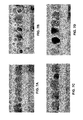
- FIGS. 7A-8D the grain growth resulting from the inventors' exemplary experimentation is presented.
- FIGS. 7A and 8A correspond to a dual layered recording layer, each of the layers incorporating a BN ⁇ C segregant.
- FIG. 7A depicts the grains having desirable flat interfaces at the tops and bottoms of the grains, there is also joining between magnetic grains. Joining between grains undesirably results in grains having large diameters, thereby reducing the recording density of the recording layer and causing poor magnetic properties. This joining is also apparent in the top down view of FIG. 8A .
- FIGS. 7B and 8B illustrate a dual layered recording layer, each of the layers having a C segregant.
- the C segregant was found to cause the grains to become rounded, limiting the achievable thickness of the recording layer as a whole.
- additional smaller grains are formed, interspersed among the main grain structures, as noted by the white circles in FIG. 7B .
- the magnetic orientations of these smaller grains are flipped frequently and are oriented randomly, which significantly increases the noise when attempting to read the data stored on the main grain structures.
- the grains in the present embodiment had poor structural composition, the isolation of each of the grains by the segregant was desirable.
- FIGS. 7C and 8C illustrate an attempt to incorporate both BN ⁇ C and C in the dual layered recording layer to combine the different desirable results seen in FIGS. 7A-7B and 8A-8B .
- the first (bottom) of the dual layers implemented a BN ⁇ C segregant
- the second (top) of the dual layers implemented a C segregant.
- the cross-sectional view in FIG. 7C still shows the grains as having undesirable rounded edges while the top down view of FIG. 8C shows poor isolation of each of the grains.
- the inventors implemented C as the segregant for the first layer of the dual layered recording layer, and BN ⁇ C for the second segregant in the second layer.
- C the segregant for the first layer of the dual layered recording layer
- BN ⁇ C the second segregant in the second layer.
- the inventors were able to influence sound magnetic properties and isolation of the grains in the first layer of the dual layered recording layer, and encourage improved structural characteristics of the grains in the second magnetic layer.
- the inventors were able to translate each of the segregants' desirable properties to the magnetic grains.
- the recording layer may take advantage of the properties of one segregant with respect to one aspect of the grain, while adopting properties of another segregant for other aspects.
- the primarily C-based first segregant layer promotes good grain separation, while use of a BN ⁇ C or the like-based second segregant layer promotes a more columnar shape of the grains, thereby resulting in various beneficial and novel grain structures described herein.
- the inventors were able to construct grains having smaller diameters, reduce the formation of thermally unstable grains (e.g., having a thickness less than 3 nm), achieve reduced media surface roughness, and maintain desirable magnetic properties of the magnetic medium.
- FIG. 6 depicts a magnetic medium 600 according to an exemplary embodiment, which is in no way intended to limit the invention.
- the present magnetic medium 600 may be implemented in conjunction with features from any other embodiment listed herein, such as those described with reference to the other FIGS.
- magnetic medium 600 and others presented herein may be used in various applications and/or in permutations which may or may not be specifically described in the illustrative embodiments listed herein.
- the magnetic medium 600 illustrates a variation of the embodiment of FIG. 5A , depicting a detailed layered structure of the magnetic medium 600 . Accordingly, various components of FIG. 6 have common numbering with those of FIG. 5A . Further, the magnetic medium 600 presented herein may be used in any desired environment.
- the magnetic medium 600 includes a seed layer 504 above a substrate layer 502 .
- seed layer 504 there may be soft under layers 506 , 610 , which are illustrated as being separated by a thin spacer layer 608 , e.g., of Ru or other nonmagnetic material.
- the seed layer 504 may have a preferred thickness of about 33 nm and the soft under layers 506 , 610 may have a preferred thickness of about 15 nm, but the respective thickness of either layer may be higher or lower depending on the desired embodiment.
- the magnetic medium 600 further includes a pair of layers 612 , 616 , which are separated by an MgO layer 614 .
- One or both of the layers 612 , 616 preferably act as heat sinks, thereby dissipating heat generated when performing HAMR operations as described above.
- Illustrative materials for one or both layers 612 , 616 include Cr, Cu, Au, Ag, W, Mo, etc. and alloys thereof such as CuX, AuX, AgX etc.
- MgO layer 618 MgO—SiO 2 layer 620 and FePt layer 621 are included.
- one or more of the aforementioned layers 618 , 620 , 621 may act as a texture defining layer, e.g., which influences the epitaxial growth of the magnetic layers formed there above.
- other materials may be used to form a texture defining layer as would be appreciate by one skilled in the art upon reading the present description.
- the magnetic medium 600 includes a recording layer 508 and a cap layer 630 , above the texture defining layers 618 , 620 , 621 .
- the cap layer 630 may include any conventional magnetic cap layer, e.g., FePt.
- the cap 630 may act as a protective coating for the magnetic layers 510 , 512 therebelow.
- the cap 630 may be a continuous exchange layer, but is not limited thereto.
- a carbonaceous overcoat layer (not shown) may be formed above the cap layer 630 .
- the recording layer 508 may include a first magnetic layer 510 having a first segregant 516 , and a second magnetic layer 512 having a second segregant 518 .
- Composite magnetic grains 522 are defined by grain boundaries interfacing with the segregants.
- any of the magnetic layers 510 , 512 may include any of the materials, dimensions, etc., as described herein.
- a magnetic medium may include additional magnetic layers, e.g., in the recording layer thereof.
- any of the structures and/or steps may be implemented using known materials and/or techniques, as would become apparent to one skilled in the art upon reading the present specification.
Abstract
Description
Claims (23)
Priority Applications (1)
| Application Number | Priority Date | Filing Date | Title |
|---|---|---|---|
| US14/084,535 US9324353B2 (en) | 2013-11-19 | 2013-11-19 | Dual segregant heat assisted magnetic recording (HAMR) media |
Applications Claiming Priority (1)
| Application Number | Priority Date | Filing Date | Title |
|---|---|---|---|
| US14/084,535 US9324353B2 (en) | 2013-11-19 | 2013-11-19 | Dual segregant heat assisted magnetic recording (HAMR) media |
Publications (2)
| Publication Number | Publication Date |
|---|---|
| US20150138939A1 US20150138939A1 (en) | 2015-05-21 |
| US9324353B2 true US9324353B2 (en) | 2016-04-26 |
Family
ID=53173192
Family Applications (1)
| Application Number | Title | Priority Date | Filing Date |
|---|---|---|---|
| US14/084,535 Active 2034-03-29 US9324353B2 (en) | 2013-11-19 | 2013-11-19 | Dual segregant heat assisted magnetic recording (HAMR) media |
Country Status (1)
| Country | Link |
|---|---|
| US (1) | US9324353B2 (en) |
Cited By (8)
| Publication number | Priority date | Publication date | Assignee | Title |
|---|---|---|---|---|
| US20160148632A1 (en) * | 2014-11-26 | 2016-05-26 | HGST Netherlands B.V. | Heat assisted magnetic recording (hamr) media having a highly ordered crystalline structure |
| US9443545B2 (en) | 2013-12-24 | 2016-09-13 | HGST Netherlands B.V. | Thermally stable Au alloys as a heat diffusion and plasmonic underlayer for heat-assisted magnetic recording (HAMR) media |
| US20170365286A1 (en) * | 2015-09-17 | 2017-12-21 | Fuji Electric Co., Ltd. | Perpendicular magnetic recording medium |
| US20180174605A1 (en) * | 2016-12-21 | 2018-06-21 | Showa Denko K.K. | Magnetic recording medium, method for manufacturing magnetic recording medium and magnetic recording and reproducing apparatus |
| US10020016B2 (en) * | 2013-12-10 | 2018-07-10 | Fuji Electric Co., Ltd. | Perpendicular magnetic recording medium |
| US10210894B1 (en) * | 2017-09-19 | 2019-02-19 | Kabushiki Kaisha Toshiba | Magnetic recording medium including multiple magnetic layers with multiple regions having aligned easy magnetization axes and magnetic recording and reproducing device |
| US10832720B2 (en) * | 2016-12-08 | 2020-11-10 | Showa Denko K.K. | Magnetic recording medium with nitride segregant, method for manufacturing same and magnetic recording and reproducing apparatus |
| US11948614B2 (en) | 2022-02-21 | 2024-04-02 | Seagate Technology Llc | Methods of manufacturing at least a portion of a magnetic layer of a magnetic recording disk, and related magnetic recording disks |
Families Citing this family (14)
| Publication number | Priority date | Publication date | Assignee | Title |
|---|---|---|---|---|
| JP6163744B2 (en) * | 2012-12-06 | 2017-07-19 | 富士電機株式会社 | Perpendicular magnetic recording medium |
| MY167287A (en) * | 2012-12-06 | 2018-08-15 | Fuji Electric Co Ltd | Perpendicular magnetic recording medium |
| US20160225393A1 (en) * | 2013-09-12 | 2016-08-04 | National Institute For Materials Science | Perpendicular magnetic recording medium and method for producing the same |
| MY164347A (en) * | 2014-05-12 | 2017-12-15 | Fuji Electric Co Ltd | Method for manufacturing perpendicular magnetic recording medium |
| JP6260517B2 (en) * | 2014-11-20 | 2018-01-17 | 富士電機株式会社 | Magnetic recording medium and method for manufacturing the same |
| MY166441A (en) * | 2015-07-02 | 2018-06-27 | Fuji Electric Co Ltd | Magnetic recording medium |
| US9779771B1 (en) * | 2015-07-28 | 2017-10-03 | Seagate Technology Llc | Capping layer for magnetic recording stack |
| US9406329B1 (en) * | 2015-11-30 | 2016-08-02 | WD Media, LLC | HAMR media structure with intermediate layer underlying a magnetic recording layer having multiple sublayers |
| US9601145B1 (en) | 2016-05-25 | 2017-03-21 | HGST Netherlands B.V. | Heat-assisted magnetic recording (HAMR) disk with multiple continuous magnetic recording layers |
| US9601144B1 (en) | 2016-05-25 | 2017-03-21 | HGST Netherlands B.V. | Heat-assisted magnetic recording (HAMR) disk drive with disk having multiple continuous magnetic recording layers |
| JPWO2017221573A1 (en) * | 2016-06-23 | 2018-09-20 | 富士電機株式会社 | Magnetic recording medium |
| JP6989427B2 (en) | 2018-03-23 | 2022-01-05 | 昭和電工株式会社 | Magnetic recording medium and magnetic recording / playback device |
| JP7049182B2 (en) | 2018-05-21 | 2022-04-06 | 昭和電工株式会社 | Magnetic recording medium and magnetic storage device |
| US20230267958A1 (en) * | 2022-02-21 | 2023-08-24 | Seagate Technology Llc | A magnetic layer of a magnetic recording disk, and related magnetic recording disks |
Citations (50)
| Publication number | Priority date | Publication date | Assignee | Title |
|---|---|---|---|---|
| US5981017A (en) | 1997-12-19 | 1999-11-09 | Western Digital Corporation | Magnetic disk having a heat sink layer above the substrate and method of making |
| JP2000332318A (en) | 1998-06-30 | 2000-11-30 | Toshiba Corp | Magnetoresistive effect element, magnetic head, magnetic head assembly and magnetic recorder |
| US20040081031A1 (en) | 2002-11-05 | 2004-04-29 | Hideki Saga | Recording head and information recording apparatus |
| US20050202287A1 (en) | 2004-03-10 | 2005-09-15 | Seagate Technology Llc | Thermally isolated granular media for heat assisted magnetic recording |
| US20060269794A1 (en) | 2005-05-27 | 2006-11-30 | Kabushiki Kaisha Toshiba | Perpendicular magnetic recording medium and perpendicular magnetic recording/reproducing apparatus |
| US7235750B1 (en) | 2005-01-31 | 2007-06-26 | United States Of America As Represented By The Secretary Of The Air Force | Radio frequency MEMS switch contact metal selection |
| US20070253116A1 (en) | 2006-04-28 | 2007-11-01 | Hiromasa Takahashi | Magnetic reading head |
| US20080026255A1 (en) | 2006-07-28 | 2008-01-31 | Heraeus, Inc. | Alloy and architecture design for heat-assisted magnetic recording |
| EP1887568A1 (en) | 2006-08-02 | 2008-02-13 | Po-Cheng Kuo | Heat assisted magnetic recording medium and method for fabricating the same |
| US20080090106A1 (en) | 2006-10-13 | 2008-04-17 | David Braunstein | Soft underlayer for perpendicular media with mechanical stability and corrosion resistance |
| JP2008091024A (en) | 2007-12-25 | 2008-04-17 | Toshiba Corp | Perpendicular magnetic recording medium |
| JP2009064501A (en) | 2007-09-05 | 2009-03-26 | Showa Denko Kk | Magnetic recording medium and magnetic recording and playback apparatus |
| US7678476B2 (en) | 2006-01-20 | 2010-03-16 | Seagate Technology Llc | Composite heat assisted magnetic recording media with temperature tuned intergranular exchange |
| US20100149676A1 (en) | 2008-07-18 | 2010-06-17 | The Regents Of The University Of California | Three-dimensional magnetic recording |
| US20100182714A1 (en) | 2008-12-01 | 2010-07-22 | Showa Denko K.K. | Thermal-assist magnetic recording medium and magnetic recording and reproducing apparatus |
| JP2010182386A (en) | 2009-02-09 | 2010-08-19 | Fuji Electric Device Technology Co Ltd | Magnetic recording medium |
| US20100284104A1 (en) | 2007-11-26 | 2010-11-11 | Commissariat A I'energie Atomique Et Aux Energies Alternatives | Magnetic recording medium |
| US7838135B2 (en) | 2006-03-13 | 2010-11-23 | Po-Cheng Kuo | Heat assisted magnetic recording medium and method for fabricating the same |
| US20100315735A1 (en) | 2009-06-15 | 2010-12-16 | Headway Technologies, Inc. | Plasmon antenna with magnetic core for thermally assisted magnetic recording |
| US7862914B2 (en) | 2005-07-26 | 2011-01-04 | Seagate Technology Llc | Heatsink films for magnetic recording media |
| US7869162B2 (en) | 2007-02-16 | 2011-01-11 | Seagate Technology Llc | Thin film structure with controlled lateral thermal spreading in the thin film |
| US20110096431A1 (en) | 2009-10-28 | 2011-04-28 | Olav Hellwig | Joint design of thermally-assisted magnetic recording head and patterned media for high optical efficiency |
| US20110193097A1 (en) | 2010-02-09 | 2011-08-11 | Tracy Autry | Silicon carbide semiconductor |
| US20110235479A1 (en) | 2010-03-29 | 2011-09-29 | Showa Denko K.K. | Thermally assisted magnetic recording medium and magnetic recording storage |
| US8114470B2 (en) | 2008-11-26 | 2012-02-14 | Seagate Technology Llc | Reduced spacing recording apparatus |
| US20120052330A1 (en) * | 2010-08-26 | 2012-03-01 | Hitachi, Ltd. | Perpendicular magnetic recording medium and manufacturing method of the same |
| US8173282B1 (en) * | 2009-12-11 | 2012-05-08 | Wd Media, Inc. | Perpendicular magnetic recording medium with an ordering temperature reducing layer |
| US20120123525A1 (en) | 2010-11-17 | 2012-05-17 | Kramer-Brown Pamela A | Radiopaque intraluminal stents comprising cobalt-based alloys containing one or more platinum group metals, refractory metals, or combinations thereof |
| JP2012104212A (en) | 2010-11-08 | 2012-05-31 | Hitachi Global Storage Technologies Netherlands Bv | Head structure for heat-assisted recording (tar) disk drive |
| US20120225325A1 (en) * | 2011-03-02 | 2012-09-06 | Hitachi, Ltd. | Magnetic recording medium |
| US20120225323A1 (en) | 2009-11-18 | 2012-09-06 | Kabushiki Kaisha Kobe Seiko Sho (Kobe Steel, Ltd.) | Ag ALLOY THERMAL DIFFUSION CONTROL FILM FOR USE IN MAGNETIC RECORDING MEDIUM FOR HEAT-ASSISTED MAGNETIC RECORDING, MAGNETIC RECORDING MEDIUM FOR HEAT-ASSISTED MAGNETIC RECORDING, AND SPUTTERING TARGET |
| US8268462B2 (en) * | 2008-12-22 | 2012-09-18 | Seagate Technology Llc | Hybrid grain boundary additives |
| US20120237791A1 (en) | 2011-03-17 | 2012-09-20 | Enlight Corporation | Heat conductive composite substrate having heat dissipation properties and manufacturing method thereof |
| US20120251845A1 (en) | 2011-03-31 | 2012-10-04 | Seagate Technology Llc | Exchange coupled magnetic elements |
| US20120251842A1 (en) | 2011-03-31 | 2012-10-04 | Wd Media, Inc. | Low roughness heatsink design for heat assisted magnetic recording media |
| US20120300600A1 (en) | 2010-01-26 | 2012-11-29 | Showa Denko K.K. | Thermally assisted magnetic recording medium and magnetic recording and reproducing device |
| US8345374B2 (en) | 2003-05-29 | 2013-01-01 | Seagate Technology, Llc | Patterned media for heat assisted magnetic recording |
| US20130004796A1 (en) | 2011-06-30 | 2013-01-03 | Seagate Technology Llc | Recording layer for heat assisted magnetic recording |
| US8399051B1 (en) | 2011-09-29 | 2013-03-19 | HGST Netherlands B.V. | Method for making a patterned perpendicular magnetic recording disk having a FePt or CoPt chemically ordered recording layer |
| US20130071695A1 (en) * | 2008-12-22 | 2013-03-21 | Seagate Technology Llc | Hybrid Grain Boundary Additives in Granular Media |
| WO2013044133A1 (en) | 2011-09-23 | 2013-03-28 | Carnegie Mellon University | Thin-film media structures for perpendicular magnetic recording and storage devices made therewith |
| US8460805B1 (en) | 2010-12-23 | 2013-06-11 | Seagate Technology Llc | Magnetic layers |
| US20130201805A1 (en) | 2012-02-02 | 2013-08-08 | Seagate Technology Llc | Active Media for Heat Assisted Magnetic Recording (HAMR) |
| US8509039B1 (en) | 2012-06-28 | 2013-08-13 | HGST Netherlands B.V. | Thermally-assisted recording (TAR) disk with low thermal-conductivity underlayer |
| US8530065B1 (en) * | 2010-08-10 | 2013-09-10 | WD Media, LLC | Composite magnetic recording medium |
| US20130270505A1 (en) | 2011-10-10 | 2013-10-17 | Altis Semiconductor | Microelectronic device with programmable memory, including a layer of doped chalcogenide that withstands high temperatures |
| US8623670B1 (en) | 2012-07-15 | 2014-01-07 | HGST Netherlands B.V. | Method for making a perpendicular thermally-assisted recording (TAR) magnetic recording disk having a carbon segregant |
| US20140153128A1 (en) * | 2012-11-30 | 2014-06-05 | Kabushiki Kaisha Toshiba | Magnetic recording medium, method of manufacturing the same, and magnetic recording/reproduction apparatus |
| US8889275B1 (en) * | 2010-08-20 | 2014-11-18 | WD Media, LLC | Single layer small grain size FePT:C film for heat assisted magnetic recording media |
| US20150179204A1 (en) | 2013-12-24 | 2015-06-25 | HGST Netherlands B.V. | Thermally stable au alloys as a heat diffusion and plasmonic underlayer for heat-assisted magnetic recording (hamr) media |
-
2013
- 2013-11-19 US US14/084,535 patent/US9324353B2/en active Active
Patent Citations (55)
| Publication number | Priority date | Publication date | Assignee | Title |
|---|---|---|---|---|
| US5981017A (en) | 1997-12-19 | 1999-11-09 | Western Digital Corporation | Magnetic disk having a heat sink layer above the substrate and method of making |
| JP2000332318A (en) | 1998-06-30 | 2000-11-30 | Toshiba Corp | Magnetoresistive effect element, magnetic head, magnetic head assembly and magnetic recorder |
| US20040081031A1 (en) | 2002-11-05 | 2004-04-29 | Hideki Saga | Recording head and information recording apparatus |
| US8345374B2 (en) | 2003-05-29 | 2013-01-01 | Seagate Technology, Llc | Patterned media for heat assisted magnetic recording |
| US20050202287A1 (en) | 2004-03-10 | 2005-09-15 | Seagate Technology Llc | Thermally isolated granular media for heat assisted magnetic recording |
| US7235750B1 (en) | 2005-01-31 | 2007-06-26 | United States Of America As Represented By The Secretary Of The Air Force | Radio frequency MEMS switch contact metal selection |
| US20060269794A1 (en) | 2005-05-27 | 2006-11-30 | Kabushiki Kaisha Toshiba | Perpendicular magnetic recording medium and perpendicular magnetic recording/reproducing apparatus |
| US7862914B2 (en) | 2005-07-26 | 2011-01-04 | Seagate Technology Llc | Heatsink films for magnetic recording media |
| US7678476B2 (en) | 2006-01-20 | 2010-03-16 | Seagate Technology Llc | Composite heat assisted magnetic recording media with temperature tuned intergranular exchange |
| US7838135B2 (en) | 2006-03-13 | 2010-11-23 | Po-Cheng Kuo | Heat assisted magnetic recording medium and method for fabricating the same |
| US20070253116A1 (en) | 2006-04-28 | 2007-11-01 | Hiromasa Takahashi | Magnetic reading head |
| JP2008034078A (en) | 2006-07-28 | 2008-02-14 | Heraeus Inc | Magnetic recording medium and its manufacturing method |
| US20080026255A1 (en) | 2006-07-28 | 2008-01-31 | Heraeus, Inc. | Alloy and architecture design for heat-assisted magnetic recording |
| EP1887568A1 (en) | 2006-08-02 | 2008-02-13 | Po-Cheng Kuo | Heat assisted magnetic recording medium and method for fabricating the same |
| US20080090106A1 (en) | 2006-10-13 | 2008-04-17 | David Braunstein | Soft underlayer for perpendicular media with mechanical stability and corrosion resistance |
| US7869162B2 (en) | 2007-02-16 | 2011-01-11 | Seagate Technology Llc | Thin film structure with controlled lateral thermal spreading in the thin film |
| US20110116189A1 (en) | 2007-09-05 | 2011-05-19 | Showa Denko K.K. | Magnetic recording medium and magnetic recording/reproducing device |
| JP2009064501A (en) | 2007-09-05 | 2009-03-26 | Showa Denko Kk | Magnetic recording medium and magnetic recording and playback apparatus |
| US20100284104A1 (en) | 2007-11-26 | 2010-11-11 | Commissariat A I'energie Atomique Et Aux Energies Alternatives | Magnetic recording medium |
| JP2008091024A (en) | 2007-12-25 | 2008-04-17 | Toshiba Corp | Perpendicular magnetic recording medium |
| US20100149676A1 (en) | 2008-07-18 | 2010-06-17 | The Regents Of The University Of California | Three-dimensional magnetic recording |
| US8114470B2 (en) | 2008-11-26 | 2012-02-14 | Seagate Technology Llc | Reduced spacing recording apparatus |
| US20100182714A1 (en) | 2008-12-01 | 2010-07-22 | Showa Denko K.K. | Thermal-assist magnetic recording medium and magnetic recording and reproducing apparatus |
| US8268462B2 (en) * | 2008-12-22 | 2012-09-18 | Seagate Technology Llc | Hybrid grain boundary additives |
| US20130071695A1 (en) * | 2008-12-22 | 2013-03-21 | Seagate Technology Llc | Hybrid Grain Boundary Additives in Granular Media |
| JP2010182386A (en) | 2009-02-09 | 2010-08-19 | Fuji Electric Device Technology Co Ltd | Magnetic recording medium |
| US20100315735A1 (en) | 2009-06-15 | 2010-12-16 | Headway Technologies, Inc. | Plasmon antenna with magnetic core for thermally assisted magnetic recording |
| US20110096431A1 (en) | 2009-10-28 | 2011-04-28 | Olav Hellwig | Joint design of thermally-assisted magnetic recording head and patterned media for high optical efficiency |
| US20120225323A1 (en) | 2009-11-18 | 2012-09-06 | Kabushiki Kaisha Kobe Seiko Sho (Kobe Steel, Ltd.) | Ag ALLOY THERMAL DIFFUSION CONTROL FILM FOR USE IN MAGNETIC RECORDING MEDIUM FOR HEAT-ASSISTED MAGNETIC RECORDING, MAGNETIC RECORDING MEDIUM FOR HEAT-ASSISTED MAGNETIC RECORDING, AND SPUTTERING TARGET |
| US8173282B1 (en) * | 2009-12-11 | 2012-05-08 | Wd Media, Inc. | Perpendicular magnetic recording medium with an ordering temperature reducing layer |
| US20120300600A1 (en) | 2010-01-26 | 2012-11-29 | Showa Denko K.K. | Thermally assisted magnetic recording medium and magnetic recording and reproducing device |
| US20110193097A1 (en) | 2010-02-09 | 2011-08-11 | Tracy Autry | Silicon carbide semiconductor |
| US20110235479A1 (en) | 2010-03-29 | 2011-09-29 | Showa Denko K.K. | Thermally assisted magnetic recording medium and magnetic recording storage |
| US8530065B1 (en) * | 2010-08-10 | 2013-09-10 | WD Media, LLC | Composite magnetic recording medium |
| US8889275B1 (en) * | 2010-08-20 | 2014-11-18 | WD Media, LLC | Single layer small grain size FePT:C film for heat assisted magnetic recording media |
| JP2012048784A (en) | 2010-08-26 | 2012-03-08 | Hitachi Ltd | Perpendicular magnetic recording medium and manufacturing method thereof |
| US20120052330A1 (en) * | 2010-08-26 | 2012-03-01 | Hitachi, Ltd. | Perpendicular magnetic recording medium and manufacturing method of the same |
| JP2012104212A (en) | 2010-11-08 | 2012-05-31 | Hitachi Global Storage Technologies Netherlands Bv | Head structure for heat-assisted recording (tar) disk drive |
| US20120123525A1 (en) | 2010-11-17 | 2012-05-17 | Kramer-Brown Pamela A | Radiopaque intraluminal stents comprising cobalt-based alloys containing one or more platinum group metals, refractory metals, or combinations thereof |
| US8460805B1 (en) | 2010-12-23 | 2013-06-11 | Seagate Technology Llc | Magnetic layers |
| US20120225325A1 (en) * | 2011-03-02 | 2012-09-06 | Hitachi, Ltd. | Magnetic recording medium |
| US20120237791A1 (en) | 2011-03-17 | 2012-09-20 | Enlight Corporation | Heat conductive composite substrate having heat dissipation properties and manufacturing method thereof |
| US20120251842A1 (en) | 2011-03-31 | 2012-10-04 | Wd Media, Inc. | Low roughness heatsink design for heat assisted magnetic recording media |
| US20120251845A1 (en) | 2011-03-31 | 2012-10-04 | Seagate Technology Llc | Exchange coupled magnetic elements |
| US20130004796A1 (en) | 2011-06-30 | 2013-01-03 | Seagate Technology Llc | Recording layer for heat assisted magnetic recording |
| US8507114B2 (en) | 2011-06-30 | 2013-08-13 | Seagate Technology Llc | Recording layer for heat assisted magnetic recording |
| WO2013044133A1 (en) | 2011-09-23 | 2013-03-28 | Carnegie Mellon University | Thin-film media structures for perpendicular magnetic recording and storage devices made therewith |
| US20140233363A1 (en) * | 2011-09-23 | 2014-08-21 | Camegie Mellon University | Thin Film Media Structure For Perpendicular Magnetic Recording and Storage Devices Made Therewith |
| US8399051B1 (en) | 2011-09-29 | 2013-03-19 | HGST Netherlands B.V. | Method for making a patterned perpendicular magnetic recording disk having a FePt or CoPt chemically ordered recording layer |
| US20130270505A1 (en) | 2011-10-10 | 2013-10-17 | Altis Semiconductor | Microelectronic device with programmable memory, including a layer of doped chalcogenide that withstands high temperatures |
| US20130201805A1 (en) | 2012-02-02 | 2013-08-08 | Seagate Technology Llc | Active Media for Heat Assisted Magnetic Recording (HAMR) |
| US8509039B1 (en) | 2012-06-28 | 2013-08-13 | HGST Netherlands B.V. | Thermally-assisted recording (TAR) disk with low thermal-conductivity underlayer |
| US8623670B1 (en) | 2012-07-15 | 2014-01-07 | HGST Netherlands B.V. | Method for making a perpendicular thermally-assisted recording (TAR) magnetic recording disk having a carbon segregant |
| US20140153128A1 (en) * | 2012-11-30 | 2014-06-05 | Kabushiki Kaisha Toshiba | Magnetic recording medium, method of manufacturing the same, and magnetic recording/reproduction apparatus |
| US20150179204A1 (en) | 2013-12-24 | 2015-06-25 | HGST Netherlands B.V. | Thermally stable au alloys as a heat diffusion and plasmonic underlayer for heat-assisted magnetic recording (hamr) media |
Non-Patent Citations (22)
| Title |
|---|
| Advisory Action from U.S. Appl. No. 14/140,408, dated Dec. 7, 2015. |
| Challener et al., "Heat-assisted magnetic recording by a near-field transducer with efficient optical energy transfer," Nature Photonics, vol. 3, Apr. 2009, pp. 220-224. |
| Final Office Action from U.S. Appl. No. 14/140,408, dated Sep. 3, 2015. |
| Granz et al., "Granular L10 FePt:X (X = Ag, B, C, SiOx, TaOx) thin films for heat assisted magnetic recording," The European Physical Journal B, vol. 86, No. 81, 2013, pp. 1-7. |
| Hirotsune et al., U.S. Appl. No. 14/522,554, filed Oct. 23, 2014. |
| Kryder, M.H. et al., "Heat Assisted Magnetic Recording," Proceedings of the IEEE, vol. 96, No. 11, Nov. 2008, pp. 1810-1835. |
| Lim et al., "Interfacial Effects of MgO Buffer Layer on Perpendicular Anisotropy of L 10 FePt Films," IEEE Transactions on Magnetics, vol. 42, No. 10, Oct. 2006, pp. 3017-3019. |
| Mosendz et al., U.S. Appl. No. 14/140,408, filed Dec. 24, 2013. |
| Mosendz, O. et al., "Ultra-high coercivity small-grain FePt media for thermally assisted recording," Journal of Applied Physics 111, 07B729, 2012, pp. 07B729-1-07B729-4. |
| Non-Final Office Action from U.S. Appl. No. 14/140,408, dated Apr. 23, 2015. |
| Non-Final Office Action from U.S. Appl. No. 14/140,408, dated Feb. 2, 2016. |
| Non-Final Office Action from U.S. Appl. No. 14/522,554, dated Mar. 10, 2016. |
| Office Action from Japanese Application No. 2014-258951, dated Dec. 18, 2015. |
| Pan et al., "Heat-assisted magnetic recording," Nature Photonics, vol. 3, Apr. 2009, pp. 189-190. |
| Pisana, S. et al., "Effects of grain microstructure on magnetic properties in FePtAg-C media for temperature assisted recording," Journal of Applied Physics, 113, 043910, 2013, pp. 043910-1-043910-6. |
| Schuller et al., "Plasmonics for extreme light concentration and manipulation," Nature Materials, vol. 9, Mar. 2010, pp. 193-204. |
| Statement of Relevance of JP2008091024, 1 page, (document published 2008). |
| Statement of Relevance of Non-Translated Foreign Document for JP2010182386. |
| U.S. Appl. No. 14/505,440, filed Oct. 2, 2014. |
| Varaprasad, B. et al., "L10 ordered FePt based perpendicular recording media for heat assisted magnetic recording heat assisted magnetic recording," IEEE Transactions on Magnetics, vol. 49, Issue 2, 2013, pp. 718-722. |
| Weller et al., "A HAMR Media Technology Roadmap to an Areal Density of 4 Tb/in2," IEEE Transaction on Magnetics, vol. 50, No. 1, Jan. 2014, pp. 1-8. |
| Weller, D. et al., "L10 FePtX-Y media for heat-assisted magnetic recording," Phys. Status Solidi A, 210, No. 7, Wiley-VCH Verlag GmbH & Co., 2013, pp. 1245-1260. |
Cited By (11)
| Publication number | Priority date | Publication date | Assignee | Title |
|---|---|---|---|---|
| US10020016B2 (en) * | 2013-12-10 | 2018-07-10 | Fuji Electric Co., Ltd. | Perpendicular magnetic recording medium |
| US9443545B2 (en) | 2013-12-24 | 2016-09-13 | HGST Netherlands B.V. | Thermally stable Au alloys as a heat diffusion and plasmonic underlayer for heat-assisted magnetic recording (HAMR) media |
| US20160148632A1 (en) * | 2014-11-26 | 2016-05-26 | HGST Netherlands B.V. | Heat assisted magnetic recording (hamr) media having a highly ordered crystalline structure |
| US9558777B2 (en) * | 2014-11-26 | 2017-01-31 | HGST Netherlands B.V. | Heat assisted magnetic recording (HAMR) media having a highly ordered crystalline structure |
| US20170365286A1 (en) * | 2015-09-17 | 2017-12-21 | Fuji Electric Co., Ltd. | Perpendicular magnetic recording medium |
| US10714138B2 (en) * | 2015-09-17 | 2020-07-14 | Fuji Electric Co., Ltd. | Perpendicular magnetic recording medium |
| US10832720B2 (en) * | 2016-12-08 | 2020-11-10 | Showa Denko K.K. | Magnetic recording medium with nitride segregant, method for manufacturing same and magnetic recording and reproducing apparatus |
| US20180174605A1 (en) * | 2016-12-21 | 2018-06-21 | Showa Denko K.K. | Magnetic recording medium, method for manufacturing magnetic recording medium and magnetic recording and reproducing apparatus |
| US10829848B2 (en) * | 2016-12-21 | 2020-11-10 | Showa Denko K.K. | Magnetic recording medium, with carbide segregant, method for manufacturing same and magnetic recording and reproducing apparatus |
| US10210894B1 (en) * | 2017-09-19 | 2019-02-19 | Kabushiki Kaisha Toshiba | Magnetic recording medium including multiple magnetic layers with multiple regions having aligned easy magnetization axes and magnetic recording and reproducing device |
| US11948614B2 (en) | 2022-02-21 | 2024-04-02 | Seagate Technology Llc | Methods of manufacturing at least a portion of a magnetic layer of a magnetic recording disk, and related magnetic recording disks |
Also Published As
| Publication number | Publication date |
|---|---|
| US20150138939A1 (en) | 2015-05-21 |
Similar Documents
| Publication | Publication Date | Title |
|---|---|---|
| US9324353B2 (en) | Dual segregant heat assisted magnetic recording (HAMR) media | |
| GB2534649B (en) | Heat assisted magnetic recording (HAMR) media having a highly ordered crystalline structure | |
| US9406329B1 (en) | HAMR media structure with intermediate layer underlying a magnetic recording layer having multiple sublayers | |
| US9047888B2 (en) | MAMR head adapted for high speed switching | |
| US9852749B2 (en) | Near field transducer having an adhesion layer coupled thereto | |
| US9099112B1 (en) | Near field transducer having notch diffusion barrier | |
| US20160118071A1 (en) | Perpendicular magnetic recording medium and magnetic storage apparatus using the same | |
| JP6122625B2 (en) | Magnetic recording head and system having optical waveguide core and / or alloy oxide material coating | |
| US20160099017A1 (en) | Layered segregant heat assisted magnetic recording (hamr) media | |
| US9824710B1 (en) | Heat-assisted magnetic recording (HAMR) medium with thermal barrier layer in multilayered heat-sink structure | |
| US9047889B1 (en) | Perpendicular magnetic recording head having a trailing side taper angle which is less than a leading side taper angle | |
| US9552837B2 (en) | Vertically and horizontally weakly coupled perpendicular small grain media | |
| CN114446327A (en) | Heat Assisted Magnetic Recording (HAMR) media with multi-layer underlayer for recording layer | |
| US9135942B2 (en) | Heat assisted magnetic recording head having wider heat sink and pole | |
| US8059367B2 (en) | Methods for creating a magnetic main pole with side shield and systems thereof | |
| US20180137881A1 (en) | Surface treatment of magnetic recording heads for improving the robustness thereof | |
| US8614862B1 (en) | Perpendicular magnetic recording media having a cap layer above a granular layer | |
| US8634161B2 (en) | Systems having writer with deeper wrap around shield and methods for making the same | |
| US9183856B1 (en) | System and method for integration of magnetic lip and near field transducer in heat assisted magnetic recording write heads | |
| US8947828B1 (en) | Magnetic head having a double bump wrap around shield | |
| US8964336B2 (en) | Easy axis hard bias structure | |
| JP6057956B2 (en) | Granular media with high Hk assist layer for microwave assisted magnetic recording | |
| US8945732B1 (en) | Dual-magnetic layer high anisotropy media with orientation initialization layer | |
| US8551347B2 (en) | Methods for creating a stepped perpendicular magnetic pole via milling and/or metal liftoff | |
| US8947827B1 (en) | Stitched pole having a tapered tip |
Legal Events
| Date | Code | Title | Description |
|---|---|---|---|
| AS | Assignment |
Owner name: HGST NETHERLANDS B.V., NETHERLANDS Free format text: ASSIGNMENT OF ASSIGNORS INTEREST;ASSIGNORS:HELLWIG, OLAV;MOSENDZ, OLEKSANDR;PISANA, SIMONE;AND OTHERS;SIGNING DATES FROM 20131114 TO 20131115;REEL/FRAME:031955/0460 |
|
| STCF | Information on status: patent grant |
Free format text: PATENTED CASE |
|
| AS | Assignment |
Owner name: WESTERN DIGITAL TECHNOLOGIES, INC., CALIFORNIA Free format text: ASSIGNMENT OF ASSIGNORS INTEREST;ASSIGNOR:HGST NETHERLANDS B.V.;REEL/FRAME:040829/0516 Effective date: 20160831 |
|
| MAFP | Maintenance fee payment |
Free format text: PAYMENT OF MAINTENANCE FEE, 4TH YEAR, LARGE ENTITY (ORIGINAL EVENT CODE: M1551); ENTITY STATUS OF PATENT OWNER: LARGE ENTITY Year of fee payment: 4 |
|
| AS | Assignment |
Owner name: JPMORGAN CHASE BANK, N.A., AS AGENT, ILLINOIS Free format text: SECURITY INTEREST;ASSIGNOR:WESTERN DIGITAL TECHNOLOGIES, INC.;REEL/FRAME:052915/0566 Effective date: 20200113 |
|
| AS | Assignment |
Owner name: WESTERN DIGITAL TECHNOLOGIES, INC., CALIFORNIA Free format text: RELEASE OF SECURITY INTEREST AT REEL 052915 FRAME 0566;ASSIGNOR:JPMORGAN CHASE BANK, N.A.;REEL/FRAME:059127/0001 Effective date: 20220203 |
|
| AS | Assignment |
Owner name: JPMORGAN CHASE BANK, N.A., ILLINOIS Free format text: PATENT COLLATERAL AGREEMENT - A&R LOAN AGREEMENT;ASSIGNOR:WESTERN DIGITAL TECHNOLOGIES, INC.;REEL/FRAME:064715/0001 Effective date: 20230818 Owner name: JPMORGAN CHASE BANK, N.A., ILLINOIS Free format text: PATENT COLLATERAL AGREEMENT - DDTL LOAN AGREEMENT;ASSIGNOR:WESTERN DIGITAL TECHNOLOGIES, INC.;REEL/FRAME:067045/0156 Effective date: 20230818 |
|
| MAFP | Maintenance fee payment |
Free format text: PAYMENT OF MAINTENANCE FEE, 8TH YEAR, LARGE ENTITY (ORIGINAL EVENT CODE: M1552); ENTITY STATUS OF PATENT OWNER: LARGE ENTITY Year of fee payment: 8 |