US9327866B2 - Carton holder with dispensing configurations, system, and method of use - Google Patents
Carton holder with dispensing configurations, system, and method of use Download PDFInfo
- Publication number
- US9327866B2 US9327866B2 US13/754,526 US201313754526A US9327866B2 US 9327866 B2 US9327866 B2 US 9327866B2 US 201313754526 A US201313754526 A US 201313754526A US 9327866 B2 US9327866 B2 US 9327866B2
- Authority
- US
- United States
- Prior art keywords
- carton
- top surface
- removable feature
- dispensing
- front surface
- Prior art date
- Legal status (The legal status is an assumption and is not a legal conclusion. Google has not performed a legal analysis and makes no representation as to the accuracy of the status listed.)
- Active, expires
Links
- 238000000034 method Methods 0.000 title claims abstract description 24
- 238000004519 manufacturing process Methods 0.000 claims abstract description 4
- 230000036772 blood pressure Effects 0.000 description 13
- 238000011109 contamination Methods 0.000 description 7
- 230000009286 beneficial effect Effects 0.000 description 5
- 230000008901 benefit Effects 0.000 description 3
- 239000000463 material Substances 0.000 description 3
- 230000001788 irregular Effects 0.000 description 2
- 238000012986 modification Methods 0.000 description 2
- 230000004048 modification Effects 0.000 description 2
- 238000004806 packaging method and process Methods 0.000 description 2
- 238000000926 separation method Methods 0.000 description 2
- 230000004888 barrier function Effects 0.000 description 1
- 230000015572 biosynthetic process Effects 0.000 description 1
- 239000011111 cardboard Substances 0.000 description 1
- 238000012864 cross contamination Methods 0.000 description 1
- 239000011087 paperboard Substances 0.000 description 1
- 239000004033 plastic Substances 0.000 description 1
Images


Classifications
-
- B—PERFORMING OPERATIONS; TRANSPORTING
- B65—CONVEYING; PACKING; STORING; HANDLING THIN OR FILAMENTARY MATERIAL
- B65D—CONTAINERS FOR STORAGE OR TRANSPORT OF ARTICLES OR MATERIALS, e.g. BAGS, BARRELS, BOTTLES, BOXES, CANS, CARTONS, CRATES, DRUMS, JARS, TANKS, HOPPERS, FORWARDING CONTAINERS; ACCESSORIES, CLOSURES, OR FITTINGS THEREFOR; PACKAGING ELEMENTS; PACKAGES
- B65D5/00—Rigid or semi-rigid containers of polygonal cross-section, e.g. boxes, cartons or trays, formed by folding or erecting one or more blanks made of paper
- B65D5/42—Details of containers or of foldable or erectable container blanks
- B65D5/54—Lines of weakness to facilitate opening of container or dividing it into separate parts by cutting or tearing
- B65D5/5405—Lines of weakness to facilitate opening of container or dividing it into separate parts by cutting or tearing for opening containers formed by erecting a blank in tubular form
- B65D5/542—Lines of weakness to facilitate opening of container or dividing it into separate parts by cutting or tearing for opening containers formed by erecting a blank in tubular form the lines of weakness being provided in the container body
-
- B—PERFORMING OPERATIONS; TRANSPORTING
- B65—CONVEYING; PACKING; STORING; HANDLING THIN OR FILAMENTARY MATERIAL
- B65D—CONTAINERS FOR STORAGE OR TRANSPORT OF ARTICLES OR MATERIALS, e.g. BAGS, BARRELS, BOTTLES, BOXES, CANS, CARTONS, CRATES, DRUMS, JARS, TANKS, HOPPERS, FORWARDING CONTAINERS; ACCESSORIES, CLOSURES, OR FITTINGS THEREFOR; PACKAGING ELEMENTS; PACKAGES
- B65D83/00—Containers or packages with special means for dispensing contents
- B65D83/08—Containers or packages with special means for dispensing contents for dispensing thin flat articles in succession
-
- A—HUMAN NECESSITIES
- A61—MEDICAL OR VETERINARY SCIENCE; HYGIENE
- A61B—DIAGNOSIS; SURGERY; IDENTIFICATION
- A61B5/00—Measuring for diagnostic purposes; Identification of persons
- A61B5/02—Detecting, measuring or recording pulse, heart rate, blood pressure or blood flow; Combined pulse/heart-rate/blood pressure determination; Evaluating a cardiovascular condition not otherwise provided for, e.g. using combinations of techniques provided for in this group with electrocardiography or electroauscultation; Heart catheters for measuring blood pressure
- A61B5/021—Measuring pressure in heart or blood vessels
- A61B5/022—Measuring pressure in heart or blood vessels by applying pressure to close blood vessels, e.g. against the skin; Ophthalmodynamometers
- A61B5/02233—Occluders specially adapted therefor
Definitions
- Embodiments of the present invention relate generally to cartons for shipping and dispensing a plurality of products, and more particularly, relate to cartons with user selectable dispensing configurations.
- some embodiments of the present invention provide a carton that is configured to store a plurality of products for shipping while also providing dispensing configurations for dispensing the plurality of products from the carton.
- the carton may comprise material that can be torn or at least partially removed to form a dispensing configuration.
- the positioning of the carton may vary depending on the customer and available space. Indeed, the customer may wish to position the carton on a desk, mount the carton to a wall, fit the carton in a narrow space, etc.
- some embodiments of the present invention provide a carton with a plurality of removable features that enable different dispensing configurations. Indeed, depending on the positioning of the carton for dispensing, the customer may wish to create a certain dispensing configuration.
- some embodiments of the present invention provide cartons configured to store a plurality of products and provide for user selectable dispensing configurations.
- a particular product may be targeted for shipment and dispensing within some example cartons described herein.
- a product may have additional requirements or preferences during dispensing that can be addressed by some example dispensing configurations described herein.
- some embodiments of the present invention contemplate use with disposable blood pressure cuffs. Indeed, as the number of blood pressure cuffs used within an examination area increases, a need has been created to provide a carton with a dispensing configuration that promotes dispensing of disposable blood pressure cuffs in an efficient manner.
- blood pressure cuffs commonly have a number of irregular surfaces (e.g., ports, tubes, and attachment surfaces) that may engage adjacent cuffs.
- the carton may define one or more dispensing configurations that orient the cuffs in a certain manner and promote dispensing of only one cuff at a time.
- a carton for dispensing a plurality of products stored therein defines a top surface, a bottom surface, a first end, and a second end.
- the carton comprises a first removable feature associated with the top surface and positioned proximate the first end.
- the first removable feature is configured to be selectively removed from the top surface to enable removal of a portion of the first end.
- the carton further comprises a second removable feature associated with the top surface and positioned proximate the second end.
- the second removable feature is configured to be selectively removed from the top surface to enable removal of a portion of the second end.
- the carton further comprises a third removable feature associated with the top surface and positioned between the first removable feature and the second removable feature.
- the third removable feature is configured to be selectively removed from the top surface to enable removal of a portion of the top surface.
- the carton defines a closed configuration and a dispensing configuration.
- the dispensing configuration is defined by at least one of the portion of the first end being removed, the portion of the second end being removed, or the portion of the top surface being removed.
- the dispensing configuration is defined by the portion of the first end being removed to reveal a first portion of each product for dispensing. Additionally, in some embodiments, the dispensing configuration is further defined by the first portion of each product being supported by the bottom surface and a back surface of the carton. Additionally, the dispensing configuration may be further defined by a tab that extends upwardly from the bottom surface. The tab may be configured to encourage the product to be removed generally vertically before being removed generally horizontally from the carton.
- the dispensing configuration is defined by the portion of the second end being removed to reveal a second portion of each product for dispensing. In some embodiments, the dispensing configuration is defined by the portion of the top surface being removed to reveal a third portion of each product for dispensing. In some embodiments, the dispensing configuration is defined by the portion of the first end being removed to reveal a first portion of each product for dispensing and the portion of the second end being removed to reveal a second portion of each product for dispensing.
- the dispensing configuration is defined by the portion of the first end being removed to reveal a first portion of each product for dispensing, the portion of the second end being removed to reveal a second portion of each product for dispensing, and the portion of the top surface being removed to reveal a third portion of each product for dispensing.
- the carton further defines a front surface. Additionally, the first removable feature may be further associated with the front surface and positioned proximate the first end and the second removable feature may be further associated with the front surface and positioned proximate the second end.
- the first removable feature and at least a portion of the second removable feature are positioned adjacently to the third removable feature.
- the first removable feature is defined within the top surface and a front surface to extend along a first plane
- the second removable feature is defined within the top surface and the front surface to extend along a second plane
- the third removable feature is defined within the top surface to extend along a third plane.
- the first plane and the second plane may each be perpendicular to the third plane.
- the carton in the closed configuration, defines an enclosed volume configured to store the plurality of products therein for shipment purposes.
- the first removable feature and the second removable feature each comprise a perforation.
- the third removable feature may comprise a tear strip.
- a system that includes a plurality of products and a carton for dispensing and storing the plurality of products.
- the carton defines a top surface, a bottom surface, a first end, and a second end.
- the carton comprises a first removable feature associated with the top surface and positioned proximate the first end.
- the first removable feature is configured to be selectively removed from the top surface to enable removal of a portion of the first end.
- the carton further comprises a second removable feature associated with the top surface and positioned proximate the second end.
- the second removable feature is configured to be selectively removed from the top surface to enable removal of a portion of the second end.
- the carton further comprises a third removable feature associated with the top surface and positioned between the first removable feature and the second removable feature.
- the third removable feature is configured to be selectively removed from the top surface to enable removal of a portion of the top surface.
- the carton further defines a closed configuration and a dispensing configuration.
- the dispensing configuration is defined by at least one of the portion of the first end being removed, the portion of the second end being removed, or the portion of the top surface being removed.
- the dispensing configuration is defined by the portion of the first end being removed to reveal a first portion of each product for dispensing.
- the system further comprises a basket configured to receive the carton. Additionally, the basket may further comprise at least one mounting structure.
- the basket defines a first wall, an opposing second wall, a front wall, and an opposing back wall.
- the front wall and back wall may each be spaced apart from the first wall and second wall to provide access to the first removable feature and second removable feature when the carton is in the closed configuration.
- the front wall and back wall may each be spaced apart from the first wall and second wall to provide access to a portion of each product when the carton is in the dispensing configuration.
- the basket defines a first wall and an opposing second wall.
- a portion of first wall and a portion of the second wall may each be defined to extend upwardly and outwardly so as to enable easy removal of each product when the carton is in the dispensing configuration.
- a method for manufacturing a carton for dispensing a plurality of products stored therein comprises providing a carton defining a top surface, a bottom surface, a first end, and a second end.
- the method further comprises defining a first removable feature within the top surface proximate the first end.
- the first removable feature is configured to be selectively removed from the top surface to enable removal of a portion of the first end.
- the method further comprises defining a second removable feature within the top surface proximate the second end.
- the second removable feature is configured to be selectively removed from the top surface to enable removal of a portion of the second end.
- the method further comprises defining a third removable feature within the top surface extending between the first removable feature and the second removable feature.
- the third removable feature is configured to be selectively removed from the top surface to enable removal of a portion of the top surface.
- the carton defines a closed configuration and a dispensing configuration.
- the dispensing configuration is defined by at least one of the portion of the first end being removed, the portion of the second end being removed, or the portion of the top surface being removed.
- the carton defines a front surface.
- the method further comprises defining the first removable feature by defining the first removable feature within a portion of the front surface proximate the first end.
- the method further comprises defining the second removable feature by defining the second removable feature within a portion of the front surface proximate the second end.
- the method further comprises defining the first removable feature by defining a perforation within the top surface, defining the second removable feature by defining a perforation within the top surface, and/or defining the third removable feature by defining a tear strip within the top surface.
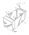
- FIG. 1 is a perspective view of a carton, in accordance with example embodiments described herein;
- FIG. 2 is a front elevation view of the carton shown in FIG. 1 , in accordance with example embodiments described herein;
- FIG. 3 is a rear elevation view of the carton shown in FIG. 1 , in accordance with example embodiments described herein;
- FIG. 4 is a top plan view of the carton shown in FIG. 1 , in accordance with example embodiments described herein;
- FIG. 5 is a bottom plan view of the carton shown in FIG. 1 , in accordance with example embodiments described herein;
- FIG. 6 is a left side elevation view of the carton shown in FIG. 1 , in accordance with example embodiments described herein;
- FIG. 7 is a right side elevation view of the carton shown in FIG. 1 , in accordance with example embodiments described herein;
- FIG. 8 is a perspective view of the carton shown in FIG. 1 , wherein a first removable feature has been partially removed, in accordance with example embodiments described herein;
- FIG. 9 is a perspective view of the carton shown in FIG. 1 , wherein a portion of the left end of the carton has been removed to form a dispensing configuration for the product stored therein, in accordance with example embodiments described herein;
- FIG. 10 is a perspective view of the carton shown in FIG. 1 , wherein a second removable feature has been partially removed, in accordance with example embodiments described herein;
- FIG. 11 is a perspective view of the carton shown in FIG. 1 , wherein a portion of the right end of the carton has been removed to form another dispensing configuration for the product stored therein, in accordance with example embodiments described herein;
- FIG. 12 is a perspective view of the carton shown in FIG. 1 , wherein a first removable feature, a second removable feature, and a third removable feature have each been partially removed, in accordance with example embodiments described herein;
- FIG. 13 is a perspective view of the carton shown in FIG. 1 , wherein a portion of the top surface of the carton has been removed to form another dispensing configuration for the product stored therein, in accordance with example embodiments described herein;
- FIG. 14 is a perspective view of the carton shown in FIG. 1 , wherein a portion of the right end of the carton and a portion of the left end of the carton have been removed to form another dispensing configuration for the product stored therein, in accordance with example embodiments described herein;
- FIG. 15 is a front elevation view of the carton shown in FIG. 14 , in accordance with example embodiments described herein;
- FIG. 16 is a perspective view of the carton shown in FIG. 1 , wherein a portion of the left end of the carton and a portion of the top surface of the carton have been removed to form another dispensing configuration for the product stored therein, in accordance with example embodiments described herein;
- FIG. 17 is a perspective view of the carton shown in FIG. 1 , wherein a portion of the right end of the carton and a portion of the top surface of the carton have each been removed to form another dispensing configuration for the product stored therein, in accordance with example embodiments described herein;
- FIG. 18 is a perspective view of the carton shown in FIG. 1 , wherein a portion of the right end of the carton, a portion of the left end of the carton, and a portion of the top surface of the carton have each been removed to form another dispensing configuration for the product stored therein, in accordance with example embodiments described herein;
- FIG. 19 is a perspective view of a basket for holding the carton shown in FIG. 1 , in accordance with example embodiments described herein;
- FIG. 20 is a perspective view of the basket shown in FIG. 19 , wherein the carton shown in FIG. 1 is positioned within the basket, in accordance with example embodiments described herein;
- FIG. 21 is a perspective view of the basket and carton shown in FIG. 20 , wherein a portion of the right end of the carton and a portion of the left end of the carton have each been removed to form a dispensing configuration for the product stored therein, in accordance with example embodiments described herein;
- FIG. 22 is a perspective view of the basket and carton shown in FIG. 20 , wherein a portion of the right end of the carton, a portion of the left end of the carton, and a portion of the top surface have each been removed to form a dispensing configuration for the product stored therein, in accordance with example embodiments described herein;
- FIG. 23 is a perspective view of another basket for holding the carton shown in FIG. 1 , in accordance with example embodiments described herein;
- FIG. 24 is a top view of the carton shown in FIG. 1 disposed in an unfolded configuration, in accordance with example embodiments described herein.
- FIG. 1 shows an example carton 10 for storing and dispensing a plurality of products according to some embodiments of the present invention.
- the carton 10 defines a top surface 12 and an opposing bottom surface 14 .
- the carton further defines a first end 32 and an opposing second end 34 .
- the carton 10 defines a front surface 22 and an opposing back surface 24 .
- the carton 10 defines a closed configuration such that the top surface 12 , bottom surface 14 , first end 32 , second end 34 , front surface 22 , and back surface 24 define an enclosed volume configured to store the plurality of products (shown, for example, in FIG. 9 ) for shipment purposes.
- the carton 10 may be made of any material (e.g., paper board, cardboard, plastic, etc.). In some embodiments, at least some portions of the carton 10 may be defined so as to be removed from the carton 10 .
- the carton 10 may define one or more removable features.
- a removable feature may define any feature that is configured to be removed from the carton (e.g., via a perforation, a tear strip, knife cuts, etc.) to enable separation of a portion of the carton with respect to the remainder of the carton.
- the carton 10 may comprise material capable of being removed (e.g., torn) so as to facilitate removal of the one or more removable features.
- the carton comprises a first removable feature associated with the top surface and positioned proximate the first end.
- the first removable feature is further associated with the front surface and positioned proximate the first end.
- the carton 10 comprises a first removable feature 40 defined within the top surface 12 and the front surface 22 proximate the first end 32 .
- the carton comprises a second removable feature associated with the top surface and positioned proximate the second end.
- the second removable feature is further associated with the front surface and positioned proximate the second end.
- the carton 10 comprises a second removable feature 50 defined within the top surface 12 and the front surface 22 proximate the second end 34 .
- the carton comprises a third removable feature associated with the top surface and positioned between the first removable feature and the second removable feature.
- the carton 10 comprises a third removable feature 60 defined within the top surface 12 extending generally between the first removable feature 40 and the second removable feature 50 .
- the first removable feature is configured to be selectively removed from the top surface to enable removal of a portion of the first end.
- the first removable feature 40 may be configured to be removed from the top surface 12 , such as represented by arrow A.
- the first removable feature 40 comprises a perforation defined within the top surface 12 of the carton 10 . While the depicted embodiment details a perforation comprising two parallel lines of perforations, other configurations are contemplated, such as a single line of perforations, a tear strip, a line of weakness, etc.
- first removable feature 40 As the first removable feature 40 is removed from the top surface 12 , a first portion 12 a of the top surface 12 is separated from the remainder of the top surface 12 . Additionally, as noted herein, the first removable feature 40 may be defined within the front surface 22 . In such an embodiment, the first removable feature 40 may also be removed from the front surface 22 so as to separate a first portion 22 a of the front surface 22 from the remainder of the front surface 22 .
- a portion of the first end 32 may be removed from the carton 10 .
- the first portion 12 a of the top surface 12 , the first portion 22 a of the front surface 22 , and a portion of the first end 32 may be removed to form a first dispensing configuration of the carton 10 (shown in FIG. 9 ).
- the first dispensing configuration is defined by the portion of the first end 32 being removed to reveal a first portion 70 a of each of a plurality of products 70 .
- example embodiments of the carton may be used for shipping and dispensing a particular product, such as blood pressure cuffs. As also noted herein, it may be beneficial to prevent contamination of each disposable blood pressure cuff. As such, in some embodiments, it may be desirable to maintain certain support structures to maintain rigidity of the carton in the dispensing configuration and also to provide a barrier to prevent contamination of the products being dispensed by minimizing exposure of the products (e.g., blood pressure cuffs) to the external environment.
- the first dispensing configuration may be further defined by the first portion of each product being supported by the bottom surface and the back surface of the carton. For example, with reference to FIG. 9 , once the portion of the first end 32 has been removed, a first portion 24 a of the back surface 24 and a first portion 14 a of the bottom surface 14 remain to provide support for the first portion 70 a of each of the plurality of products 70 .
- the disposable blood pressure cuffs may also be beneficial to prevent contamination of the disposable blood pressure cuffs during dispensing.
- adjacent cuffs can easily become stuck together during dispensing, which may cause a second cuff to be dispensed from the carton.
- that cuff becomes more prone to contamination from the external environment.
- some embodiments seek to encourage removal of only one product at a time.
- one possible product, disposable blood pressure cuffs commonly has a number of irregular surfaces (e.g., ports, tubes, and attachment surfaces) that may engage adjacent cuffs.
- the orientation of the cuffs within the carton is important to facilitate dispensing one cuff at a time.
- some embodiments of the carton encourage packaging of the cuffs horizontally along their length. Further, some embodiments contemplate one or more of the dispensing configurations of the carton defining a vertical surface (e.g., a tab) at an end of the carton, thereby requiring a user to initially lift an end of the cuff vertically prior to removing the cuff in a horizontal direction. This process is designed to promote disengagement between the cuff being removed and an adjacent cuff.
- a vertical surface e.g., a tab
- the dispensing configuration is further defined by a tab that extends upwardly from the bottom surface.
- the tab is configured to encourage the product to be removed generally vertically before being removed generally horizontally from the carton to encourage removal of only one product at a time.
- a tab 33 remains after removal of the portion of the first end 32 .
- the tab 33 extends upwardly from an edge of the first portion 14 a of the bottom surface 14 .
- the tab 33 is designed to encourage removal of the product vertically (e.g., along arrow X) and then horizontally (e.g., along arrow Y). Such a motion may encourage removal of only one product at a time.
- the second removable feature is configured to be selectively removed from the top surface to enable removal of a portion of the second end.
- the second removable feature 50 may be configured to be removed from the top surface 12 , such as represented by arrow B.
- the second removable feature 50 comprises a perforation defined within the top surface 12 of the carton 10 . While the depicted embodiment details a perforation comprising two parallel lines of perforations, other configurations are contemplated, such as a single line of perforations, a tear strip, a line of weakness, etc.
- a second portion 12 b of the top surface 12 may be separated from the remainder of the top surface 12 .
- the second removable feature 50 may be defined within the front surface 22 .
- the second removable feature 50 may also be removed from the front surface 22 so as to separate a second portion 22 b of the front surface 22 from the remainder of the front surface 22 .
- a portion of the second end 34 may be removed from the carton 10 .
- the second portion 12 b of the top surface 12 , the second portion 22 b of the front surface 22 , and a portion of the second end 34 may be removed to form a second dispensing configuration of the carton 10 (shown in FIG. 11 ).
- the second dispensing configuration is defined by the portion of the second end 34 being removed to reveal a second portion 70 b of each of a plurality of products 70 .
- the second dispensing configuration may be further defined by the second portion of each product being supported by the bottom surface and the back surface of the carton.
- the second portion of each product being supported by the bottom surface and the back surface of the carton.
- a second portion 24 b of the back surface 24 and a second portion of the bottom surface 14 b remain to provide support for the second portion 70 b of each of the plurality of products 70 .
- the dispensing configuration may be further defined by a tab that extends upwardly from the bottom surface.
- the tab is configured to encourage the product to be removed generally vertically before being removed generally horizontally from the carton to encourage removal of only one product at a time.
- a tab 35 remains after removal of the portion of the second end 34 .
- the tab 35 extends upwardly from an edge of the second portion 14 b of the bottom surface 14 .
- the tab 35 may be designed to encourage removal of the product vertically and then horizontally. Such a motion may encourage removal of only one product at a time.
- a third removable feature is configured to be selectively removed from the top surface to enable removal of a portion of the top surface.
- the third removable feature 60 may be configured to be removed from the top surface 12 , such as represented by arrow E.
- the third removable feature 60 comprises a tear strip defined within the top surface 12 of the carton 10 .
- a third portion 12 c of the top surface 12 may be separated from the remainder of the top surface 12 (shown in FIG. 13 ).
- the first removable feature 40 and/or the second removable feature 50 may be defined within the top surface 12 relative to the third removable feature 60 to enable removal of the third removable feature 60 .
- removal of the first removable feature 40 from the top surface 12 (e.g., along arrow C) and removal of the second removable feature 50 from the top surface 12 (e.g., along arrow D) may enable removal of the third removable feature 60 , such as by enabling a user to access and pull on an end of the third removable feature.
- removal of the first removable feature 40 , second removable feature 50 , and third removable feature 60 from the top surface 12 may cause the third portion 12 c of the top surface 12 to be separated from the remainder of the top surface 12 , such as for removal therefrom.
- a portion of the top surface 12 may be removed from the carton 10 .
- the third portion 12 c of the top surface 12 may be positioned away from the products or removed relative to the carton to form a third dispensing configuration (shown in FIG. 13 ).
- the third portion 12 c may be positioned away (e.g., peeled away) from the products by the user to allow for dispensing.
- the third portion 12 c (or a portion thereof) may be completely removed from the carton 10 by the user, such as by being torn or ripped off.
- the third dispensing configuration is defined by the portion of the top surface 12 being removed to reveal a third portion 70 c of each of a plurality of products 70 .
- the carton 10 may be configured to be selectively formed into dispensing configurations that are suited for a particular user.
- the dispensing configuration of the carton may be defined by at least one of the portion of the first end being removed, the portion of the second end being removed, and/or the portion of the top surface being removed.
- the removable features of the carton may be configured in certain positions with respect to each other.
- at least a portion of the first removable feature 40 and at least a portion of the second removable feature 50 may be defined within the top surface 12 adjacent to the third removable feature 60 .
- the first removable feature 40 may be defined within the top surface 12 and the front surface 22 to extend along a first plane proximate the first end 32 .
- the second removable feature 50 may be defined within the top surface 12 and the front surface 22 to extend along a second plane proximate the second end 34 .
- the third removable feature 60 may be defined within the top surface 12 to extend along a third plane that is perpendicular to the first plane and the second plane. Additionally, the third removable feature 60 may extend at one end from the first plane to a second end at the second plane. In such a manner, similar to some embodiments noted herein, partial removal of the first removable feature 40 and the second removable feature 50 may enable easy access to the perpendicular third removable feature 60 .
- the first removable feature and second removable feature each comprising a perforation and the third removable feature comprising a tear strip
- some embodiments of the present invention contemplate other configurations of features capable of being removed (e.g., the third removable feature may comprise a perforation, the first removable feature may define a tear strip, the third removable feature may define knife cuts, etc.).
- the first removable feature, second removable feature, and third removable feature are defined within the top surface and in certain configurations with respect to each other, other configurations are contemplated.
- first removable feature, second removable feature, and third removable feature may be defined in a different manner (e.g., a straight line, a curved line, etc.).
- first removable feature, second removable feature, and third removable feature may be defined such that only a portion may need to be removed to enable separation of a portion of the carton from the remainder of the carton.
- more or fewer than three different removable features are also contemplated by some embodiments of the present invention.
- the carton may be configured to selectively form other dispensing configurations.
- the carton 10 may form a fourth dispensing configuration defined by the portion of the first end 32 being removed to reveal a first portion 70 a of each of the plurality of products 70 for dispensing and the portion of the second end 34 being removed to reveal a second portion 70 b of each of the plurality of products 70 for dispensing.
- the product 70 may be dispensed from either the first end 32 or the second end 34 of the carton 10 .
- FIG. 16 Another example dispensing configuration for the carton is illustrated in FIG. 16 .
- the carton 10 forms a fifth dispensing configuration defined by the portion of the first end 32 (shown in FIG. 1 ) being removed to reveal a first portion 70 a of each of the plurality of products 70 for dispensing and the portion 12 c of the top surface 12 being removed to reveal a third portion 70 c of each of the plurality of products 70 for dispensing.
- the product 70 may be dispensed from either the first end 32 or the top of the carton 10 , or a combination of the first end 32 and the top of the carton 10 .
- FIG. 17 A further example dispensing configuration for the carton is illustrated in FIG. 17 .
- the carton 10 forms a sixth dispensing configuration defined by the portion of the second end 34 (shown in FIG. 1 ) being removed to reveal a second portion 70 b of each of the plurality of products 70 for dispensing and the portion 12 c of the top surface 12 being removed to reveal a third portion 70 c of each of the plurality of products 70 for dispensing.
- the product 70 may be dispensed from either the second end 34 or the top of the carton 10 , or a combination of the second end 34 and the top of the carton 10 .
- FIG. 18 Another example dispensing configuration for the carton is illustrated in FIG. 18 .
- the carton 10 forms a seventh dispensing configuration defined by the portion of the first end 32 (shown in FIG. 1 ) being removed to reveal a first portion 70 a of each of the plurality of products 70 for dispensing, the portion of the second end 34 being removed to reveal a second portion 70 b of each of the plurality of products 70 for dispensing, and the portion 12 c of the top surface 12 being removed to reveal a third portion 70 c of each of the plurality of products 70 for dispensing.
- the product 70 may be dispensed from any of the first end 32 , the second end 34 , or the top of the carton 10 , or any combination thereof.
- a system for shipping and dispensing products may comprise a plurality of products and a carton for storing the plurality of products.
- the carton may be embodied as define any example carton described herein, such as carton 10 .
- the system may further comprise a basket configured to receive the carton.
- the basket 80 may define a bottom 81 , a first wall 82 , an opposing second wall 84 , a front wall 85 , and an opposing back wall 87 .
- each wall e.g., front wall 85
- the basket may be configured to receive the carton 10 , such as between the respective walls (e.g., front wall 85 and first wall 82 ). Additionally, in some embodiments, adjacent walls may be spaced apart to provide access to the removable features when the carton defines the closed configuration.
- the front wall 85 of the basket 80 may be spaced apart (S 1 ) from the first wall 82 to provide access to the first removable feature 40 defined in the front surface 22 of the carton 10 .
- the front wall 85 of the basket 80 may be spaced apart from the second wall 84 to provide access to the second removable feature 50 defined in the front surface 22 of the carton 10 .
- adjacent walls may be spaced apart to provide access to the product when the carton defines a dispensing configuration.
- the front wall 85 of the basket 80 may be spaced apart from the first wall 82 to provide access to the first portion 70 a of each of the plurality of product 70 .
- the front wall 85 of the basket 80 may be spaced apart from the second wall 84 to provide access to the second portion 70 b of each of the plurality of product 70 .
- the basket 80 may be configured to provide access to the third removable feature 60 when the carton 10 is in the closed configuration.
- the basket 80 may not define a top surface so as to provide access to the top surface 12 of the carton 10 when the carton 10 is received by the basket 80 .
- the basket 80 may be configured to provide access to the third portion 70 c of each of the plurality of product 70 when the carton 10 is in a dispensing configuration.
- the first wall 82 and/or second wall 84 of the basket 80 may be defined to extend upwardly to promote removal of each product in a vertical manner and then a horizontal manner. Such a process may encourage removal of only one product at a time by facilitating the disengagement of the product to be dispensed from other products.
- the basket may be configured to be mounted to a wall.
- the basket may further comprise a mounting structure configured to be mounted to the wall.
- another example basket 80 ′ comprises two mounting structures 101 attached to wires of the back wall 87 .
- Each mounting structure 101 defines a first aperture 102 and a second aperture 103 for receiving mounting fasteners (e.g., screws) for mounting to a wall (not shown).
- the basket 80 ′ may be configured to allow for easy dispensing of the products contained in the carton 10 (shown in FIG. 22 ) by defining at least one of the first wall 82 or second wall 84 to extend outwardly and upwardly.
- the first wall 82 of the basket 80 ′ defines a portion 82 a that extends outwardly and upwardly to allow for easy dispensing of the products contained in the carton 10 (shown in FIG. 22 ).
- the second wall 84 of the basket 80 ′ defines a portion 84 a that extends outwardly and upwardly to allow for easy dispensing of the products contained in the carton 10 (shown in FIG. 22 ).
- the carton 10 may define an unfolded configuration and may be configured to be folded into a closed configuration.
- the carton 10 is illustrated in an unfolded configuration in FIG. 24 .
- the carton 10 defines the first removable feature 40 , the second removable feature 50 , and the third removable feature 60 and the front surface, back surface, top surface, bottom surface, first end, and second end (not labeled).
- the carton may define one or more illustrations that aid a user in forming a dispensing configuration.
- illustration 91 provides instructions for removing the third portion of the top surface to form the third dispensing configuration.
- Illustration 94 provides instructions for positioning the carton inside a basket and removing a portion of the first end and a portion of the second end to form the fourth dispensing configuration.
- the carton may comprise other illustrations, such as for providing information about positioning the carton within the basket properly (e.g., illustration 93 ) or proper use of one of the products, such as proper use of a disposable blood pressure cuff (e.g., illustration 90 ).
- the method may comprise providing a carton defining a top surface, a bottom surface, a first end, and a second end.
- the method may further comprise defining a first removable feature within the top surface proximate the first end.
- the first removable feature may be configured to be selectively removed from the top surface to enable removal of a portion of the first end.
- the method may further include defining a second removable feature within the top surface proximate the second end.
- the second removable feature may be configured to be selectively removed from the top surface to enable removal of a portion of the second end.
- the method may further include defining a third removable feature within the top surface.
- the third removable feature may be configured to be selectively removed from the top surface to enable removal of a portion of the top surface.
- the carton may define a closed configuration and a dispensing configuration.
- the dispensing configuration may be defined by at least one of the portion of the first end being removed, the portion of the second end being removed, and/or the portion of the top surface being removed.
- the carton may define a front surface and a back surface
- the method may further include defining the first removable feature by defining the first removable feature within a portion of the front surface proximate the first end.
- the method may further include defining the second removable feature by defining the second removable feature within a portion of the front surface proximate the second end.
- the method may further include defining the first removable feature by defining a perforation within the top surface. Additionally, the method may further include defining the second removable feature by defining a perforation within the top surface. Further, the method may include defining the third removable feature by defining a tear strip within the top surface.
- Some embodiments of the present invention provide a number of advantages.
- some embodiments of the carton described herein provide a user selectable dispensing configuration that is adaptable to the user's needs.
- Another advantage includes, in some embodiments, encouraging removal of only one product at a time to help prevent contamination.
- the carton may be designed to be received by a basket for easy mounting and dispensing possibilities.
Landscapes
- Engineering & Computer Science (AREA)
- Mechanical Engineering (AREA)
- Cartons (AREA)
- Ceramic Engineering (AREA)
Abstract
Description
Claims (13)
Priority Applications (2)
| Application Number | Priority Date | Filing Date | Title |
|---|---|---|---|
| US13/754,526 US9327866B2 (en) | 2013-01-30 | 2013-01-30 | Carton holder with dispensing configurations, system, and method of use |
| PCT/US2013/074545 WO2014120341A1 (en) | 2013-01-30 | 2013-12-12 | Carton holder with dispensing configurations, system, and method of use |
Applications Claiming Priority (1)
| Application Number | Priority Date | Filing Date | Title |
|---|---|---|---|
| US13/754,526 US9327866B2 (en) | 2013-01-30 | 2013-01-30 | Carton holder with dispensing configurations, system, and method of use |
Publications (2)
| Publication Number | Publication Date |
|---|---|
| US20140209504A1 US20140209504A1 (en) | 2014-07-31 |
| US9327866B2 true US9327866B2 (en) | 2016-05-03 |
Family
ID=51221764
Family Applications (1)
| Application Number | Title | Priority Date | Filing Date |
|---|---|---|---|
| US13/754,526 Active 2034-03-10 US9327866B2 (en) | 2013-01-30 | 2013-01-30 | Carton holder with dispensing configurations, system, and method of use |
Country Status (2)
| Country | Link |
|---|---|
| US (1) | US9327866B2 (en) |
| WO (1) | WO2014120341A1 (en) |
Cited By (2)
| Publication number | Priority date | Publication date | Assignee | Title |
|---|---|---|---|---|
| US11312531B1 (en) * | 2021-10-14 | 2022-04-26 | Rachman Ezell | Dual-action carton separation system and method of use |
| US11945627B2 (en) | 2020-05-28 | 2024-04-02 | Pratt Corrugated Holdings, Inc. | Locking box |
Citations (36)
| Publication number | Priority date | Publication date | Assignee | Title |
|---|---|---|---|---|
| US4946042A (en) * | 1988-11-29 | 1990-08-07 | Lever Brothers Company | Readily openable combination shipping and display carton |
| US5251819A (en) | 1992-03-03 | 1993-10-12 | Mchugh Sandra | Collapsible container for ease of disposal |
| US5505372A (en) | 1994-10-28 | 1996-04-09 | Graphic Packaging Corporation | Carton blank and carton |
| US5622309A (en) * | 1994-12-13 | 1997-04-22 | Fuji Xerox Office Supply Co., Ltd. | Carton for packaging cut sheets of paper |
| USD419440S (en) | 1999-04-05 | 2000-01-25 | Rieber & Son A/S | Box |
| USD421531S (en) | 1998-02-18 | 2000-03-14 | Haas Grover J | Shoe rack |
| USD431462S (en) | 1998-11-19 | 2000-10-03 | The New L&N Sales and Marketing, Inc. | Merchandising package |
| USD432912S (en) | 1998-08-26 | 2000-10-31 | Chesapeake Display & Packaging Europe | Box |
| USD472463S1 (en) | 2000-08-30 | 2003-04-01 | Kraft Foods Holdings, Inc. | Container for food products |
| JP2003095260A (en) | 2001-09-20 | 2003-04-03 | Tomusu Garden Guramu:Kk | Box |
| USD473378S1 (en) | 2002-02-12 | 2003-04-22 | Nouvel Ag | Container for newspapers, or the like |
| US20030164317A1 (en) * | 2000-05-24 | 2003-09-04 | Hitoshi Fujiwara | Package material and packaged paper sheets |
| USD490703S1 (en) | 2002-08-27 | 2004-06-01 | Coors Brewing Company | Beverage cooler carton |
| USD505620S1 (en) | 2004-04-27 | 2005-05-31 | Robert J. Huebsch | Container |
| USD511681S1 (en) | 2004-03-01 | 2005-11-22 | Kraft Foods Holdings, Inc. | Food packaging carton with susceptor tray |
| US20060255105A1 (en) | 2005-05-12 | 2006-11-16 | Frances Sweet | Carton having space saving feature |
| US20070090175A1 (en) * | 2005-09-28 | 2007-04-26 | Schemmel Garrett K | Carton with opening access feature |
| USD548583S1 (en) | 2005-11-22 | 2007-08-14 | Kraft Foods Holdings, Inc. | Joined tray and lid |
| USD551007S1 (en) | 2005-10-17 | 2007-09-18 | Waverly Plastics Company, Inc. | Bag dispenser rack |
| USD554419S1 (en) | 2006-12-18 | 2007-11-06 | 3M Innovative Properties Company | Wall mountable wire basket |
| US20070267466A1 (en) | 2006-05-18 | 2007-11-22 | Kirsten Laura Brand | Cartons With Liquid-Tight Receptacles |
| US7328798B2 (en) * | 2003-11-19 | 2008-02-12 | Meadwestvaco Packaging Systems, Llc | Carton with two-step opening feature defining yieldable dispenser |
| USD570201S1 (en) | 2007-09-14 | 2008-06-03 | Georgia-Pacific Consumer Products Lp | Container mounting bracket |
| USD583872S1 (en) | 2007-09-12 | 2008-12-30 | Sanford, L.P. | Sorter |
| US20100140337A1 (en) * | 2008-12-04 | 2010-06-10 | Brand Kirsten L | Carton with dispensing features |
| US7743944B2 (en) | 2006-06-23 | 2010-06-29 | Graphic Packaging International, Inc. | Carton having dispensing configurations |
| US7784675B2 (en) | 2006-06-23 | 2010-08-31 | Graphic Packaging International, Inc. | Carton having dispensing configurations |
| US20100298724A1 (en) | 2009-05-19 | 2010-11-25 | Welch Allyn, Inc. | Recyclable or biodegradable blood pressure cuff |
| USD628387S1 (en) | 2009-12-11 | 2010-12-07 | Lynk, Inc. | Front face of a container |
| US8033449B2 (en) * | 2006-06-23 | 2011-10-11 | Graphic Packaging International, Inc. | Cartons having dispensing configurations |
| USD650175S1 (en) | 2011-06-13 | 2011-12-13 | Justin Lee | Basket for a cooler |
| US8136717B2 (en) | 2008-05-08 | 2012-03-20 | Graphic Packaging International, Inc. | Cooler carton with zipper opening feature |
| USD670913S1 (en) | 2012-03-05 | 2012-11-20 | Lee Sheng-Kai | Basket |
| USD674637S1 (en) | 2011-12-07 | 2013-01-22 | Cardiac Science Corporation | Automated external defibrillator wall mount |
| USD678049S1 (en) | 2011-06-29 | 2013-03-19 | Amazon Technologies, Inc. | Chamfered box |
| USD699101S1 (en) | 2013-01-30 | 2014-02-11 | Welch Allyn, Inc. | Carton |
-
2013
- 2013-01-30 US US13/754,526 patent/US9327866B2/en active Active
- 2013-12-12 WO PCT/US2013/074545 patent/WO2014120341A1/en active Application Filing
Patent Citations (37)
| Publication number | Priority date | Publication date | Assignee | Title |
|---|---|---|---|---|
| US4946042A (en) * | 1988-11-29 | 1990-08-07 | Lever Brothers Company | Readily openable combination shipping and display carton |
| US5251819A (en) | 1992-03-03 | 1993-10-12 | Mchugh Sandra | Collapsible container for ease of disposal |
| US5505372A (en) | 1994-10-28 | 1996-04-09 | Graphic Packaging Corporation | Carton blank and carton |
| US5622309A (en) * | 1994-12-13 | 1997-04-22 | Fuji Xerox Office Supply Co., Ltd. | Carton for packaging cut sheets of paper |
| USD421531S (en) | 1998-02-18 | 2000-03-14 | Haas Grover J | Shoe rack |
| USD432912S (en) | 1998-08-26 | 2000-10-31 | Chesapeake Display & Packaging Europe | Box |
| USD433630S (en) | 1998-08-26 | 2000-11-14 | Chesapeake Display & Packaging Europe | Box |
| USD431462S (en) | 1998-11-19 | 2000-10-03 | The New L&N Sales and Marketing, Inc. | Merchandising package |
| USD419440S (en) | 1999-04-05 | 2000-01-25 | Rieber & Son A/S | Box |
| US20030164317A1 (en) * | 2000-05-24 | 2003-09-04 | Hitoshi Fujiwara | Package material and packaged paper sheets |
| USD472463S1 (en) | 2000-08-30 | 2003-04-01 | Kraft Foods Holdings, Inc. | Container for food products |
| JP2003095260A (en) | 2001-09-20 | 2003-04-03 | Tomusu Garden Guramu:Kk | Box |
| USD473378S1 (en) | 2002-02-12 | 2003-04-22 | Nouvel Ag | Container for newspapers, or the like |
| USD490703S1 (en) | 2002-08-27 | 2004-06-01 | Coors Brewing Company | Beverage cooler carton |
| US7328798B2 (en) * | 2003-11-19 | 2008-02-12 | Meadwestvaco Packaging Systems, Llc | Carton with two-step opening feature defining yieldable dispenser |
| USD511681S1 (en) | 2004-03-01 | 2005-11-22 | Kraft Foods Holdings, Inc. | Food packaging carton with susceptor tray |
| USD505620S1 (en) | 2004-04-27 | 2005-05-31 | Robert J. Huebsch | Container |
| US20060255105A1 (en) | 2005-05-12 | 2006-11-16 | Frances Sweet | Carton having space saving feature |
| US20070090175A1 (en) * | 2005-09-28 | 2007-04-26 | Schemmel Garrett K | Carton with opening access feature |
| USD551007S1 (en) | 2005-10-17 | 2007-09-18 | Waverly Plastics Company, Inc. | Bag dispenser rack |
| USD548583S1 (en) | 2005-11-22 | 2007-08-14 | Kraft Foods Holdings, Inc. | Joined tray and lid |
| US20070267466A1 (en) | 2006-05-18 | 2007-11-22 | Kirsten Laura Brand | Cartons With Liquid-Tight Receptacles |
| US7743944B2 (en) | 2006-06-23 | 2010-06-29 | Graphic Packaging International, Inc. | Carton having dispensing configurations |
| US7784675B2 (en) | 2006-06-23 | 2010-08-31 | Graphic Packaging International, Inc. | Carton having dispensing configurations |
| US8033449B2 (en) * | 2006-06-23 | 2011-10-11 | Graphic Packaging International, Inc. | Cartons having dispensing configurations |
| USD554419S1 (en) | 2006-12-18 | 2007-11-06 | 3M Innovative Properties Company | Wall mountable wire basket |
| USD583872S1 (en) | 2007-09-12 | 2008-12-30 | Sanford, L.P. | Sorter |
| USD570201S1 (en) | 2007-09-14 | 2008-06-03 | Georgia-Pacific Consumer Products Lp | Container mounting bracket |
| US8136717B2 (en) | 2008-05-08 | 2012-03-20 | Graphic Packaging International, Inc. | Cooler carton with zipper opening feature |
| US20100140337A1 (en) * | 2008-12-04 | 2010-06-10 | Brand Kirsten L | Carton with dispensing features |
| US20100298724A1 (en) | 2009-05-19 | 2010-11-25 | Welch Allyn, Inc. | Recyclable or biodegradable blood pressure cuff |
| USD628387S1 (en) | 2009-12-11 | 2010-12-07 | Lynk, Inc. | Front face of a container |
| USD650175S1 (en) | 2011-06-13 | 2011-12-13 | Justin Lee | Basket for a cooler |
| USD678049S1 (en) | 2011-06-29 | 2013-03-19 | Amazon Technologies, Inc. | Chamfered box |
| USD674637S1 (en) | 2011-12-07 | 2013-01-22 | Cardiac Science Corporation | Automated external defibrillator wall mount |
| USD670913S1 (en) | 2012-03-05 | 2012-11-20 | Lee Sheng-Kai | Basket |
| USD699101S1 (en) | 2013-01-30 | 2014-02-11 | Welch Allyn, Inc. | Carton |
Non-Patent Citations (5)
| Title |
|---|
| Application for Registration of an Industrial Design Examiner's Report for Application No. 152251; dated Mar. 12, 2014. |
| Application for Registration of an Industrial Design Examiner's Report for Application No. 152254; dated Mar. 12, 2014. |
| Application for Registration of an Industrial Design Examiner's Report for Application No. 152255; dated Mar. 12, 2014. |
| International Preliminary Report on Patentability for International Application No. PCT/US2013/074545 mailed Aug. 13, 2015 (12 pgs.). |
| International Search Report for International Application No. PCT/US2013/074545 mailed Mar. 26, 2014 (3 pgs.). |
Cited By (2)
| Publication number | Priority date | Publication date | Assignee | Title |
|---|---|---|---|---|
| US11945627B2 (en) | 2020-05-28 | 2024-04-02 | Pratt Corrugated Holdings, Inc. | Locking box |
| US11312531B1 (en) * | 2021-10-14 | 2022-04-26 | Rachman Ezell | Dual-action carton separation system and method of use |
Also Published As
| Publication number | Publication date |
|---|---|
| US20140209504A1 (en) | 2014-07-31 |
| WO2014120341A1 (en) | 2014-08-07 |
Similar Documents
| Publication | Publication Date | Title |
|---|---|---|
| US9828131B2 (en) | Shipping and display tray and blank for forming the same | |
| US8863417B2 (en) | End stand display system and side saddle display and product holder | |
| US20140048444A1 (en) | Combination box and display unit | |
| US8910793B2 (en) | Split case system for display containers | |
| JP2013544540A (en) | Product dispenser system | |
| US20110259947A1 (en) | Retail-ready packaging | |
| US20110000955A1 (en) | Slider Power-Wing Box | |
| RU2013142434A (en) | SHARED TRAY | |
| US20230142003A1 (en) | Retail ready packaging for carded items | |
| US20040084350A1 (en) | Self-hanging container | |
| US9327866B2 (en) | Carton holder with dispensing configurations, system, and method of use | |
| US9776760B2 (en) | Display-ready retail case with divide | |
| EP3484782B1 (en) | Shelf-ready package and method for manufacturing the same | |
| US10124943B2 (en) | Dispensing carton for a refrigerator door | |
| US10654611B2 (en) | Retail ready packaging | |
| WO2017048442A1 (en) | Built-in header for display tray | |
| US10485360B2 (en) | Dual merchandizing case | |
| EP2557046A1 (en) | Packing case | |
| JP5239344B2 (en) | hook | |
| JP5079532B2 (en) | Storage case with mount | |
| BR102018014375B1 (en) | BULL PART TO FORM A CONTAINER AND CONTAINER FORMED FROM A BULL PART | |
| JP2022054444A (en) | Product display device | |
| JP2011088641A (en) | Packaging material for displaying | |
| AU2017235910A1 (en) | Shipping and display carton | |
| WO2015047685A2 (en) | Dispensing carton for a refrigerator door |
Legal Events
| Date | Code | Title | Description |
|---|---|---|---|
| AS | Assignment |
Owner name: WELCH ALLYN, INC., NEW YORK Free format text: ASSIGNMENT OF ASSIGNORS INTEREST;ASSIGNORS:STROM, JOHN R.;MCMAHON, MICHAEL T.;KARLA, SEAN R.;AND OTHERS;REEL/FRAME:029725/0923 Effective date: 20130130 |
|
| AS | Assignment |
Owner name: JPMORGAN CHASE BANK, N.A., AS COLLATERAL AGENT, ILLINOIS Free format text: SECURITY INTEREST;ASSIGNORS:ALLEN MEDICAL SYSTEMS, INC.;HILL-ROM SERVICES, INC.;ASPEN SURGICAL PRODUCTS, INC.;AND OTHERS;REEL/FRAME:036582/0123 Effective date: 20150908 Owner name: JPMORGAN CHASE BANK, N.A., AS COLLATERAL AGENT, IL Free format text: SECURITY INTEREST;ASSIGNORS:ALLEN MEDICAL SYSTEMS, INC.;HILL-ROM SERVICES, INC.;ASPEN SURGICAL PRODUCTS, INC.;AND OTHERS;REEL/FRAME:036582/0123 Effective date: 20150908 |
|
| STCF | Information on status: patent grant |
Free format text: PATENTED CASE |
|
| AS | Assignment |
Owner name: JPMORGAN CHASE BANK, N.A., AS COLLATERAL AGENT, ILLINOIS Free format text: SECURITY AGREEMENT;ASSIGNORS:HILL-ROM SERVICES, INC.;ASPEN SURGICAL PRODUCTS, INC.;ALLEN MEDICAL SYSTEMS, INC.;AND OTHERS;REEL/FRAME:040145/0445 Effective date: 20160921 Owner name: JPMORGAN CHASE BANK, N.A., AS COLLATERAL AGENT, IL Free format text: SECURITY AGREEMENT;ASSIGNORS:HILL-ROM SERVICES, INC.;ASPEN SURGICAL PRODUCTS, INC.;ALLEN MEDICAL SYSTEMS, INC.;AND OTHERS;REEL/FRAME:040145/0445 Effective date: 20160921 |
|
| AS | Assignment |
Owner name: HILL-ROM SERVICES, INC., ILLINOIS Free format text: RELEASE BY SECURED PARTY;ASSIGNOR:JPMORGAN CHASE BANK, N.A.;REEL/FRAME:050254/0513 Effective date: 20190830 Owner name: WELCH ALLYN, INC., NEW YORK Free format text: RELEASE BY SECURED PARTY;ASSIGNOR:JPMORGAN CHASE BANK, N.A.;REEL/FRAME:050254/0513 Effective date: 20190830 Owner name: HILL-ROM COMPANY, INC., ILLINOIS Free format text: RELEASE BY SECURED PARTY;ASSIGNOR:JPMORGAN CHASE BANK, N.A.;REEL/FRAME:050254/0513 Effective date: 20190830 Owner name: VOALTE, INC., FLORIDA Free format text: RELEASE BY SECURED PARTY;ASSIGNOR:JPMORGAN CHASE BANK, N.A.;REEL/FRAME:050254/0513 Effective date: 20190830 Owner name: ANODYNE MEDICAL DEVICE, INC., FLORIDA Free format text: RELEASE BY SECURED PARTY;ASSIGNOR:JPMORGAN CHASE BANK, N.A.;REEL/FRAME:050254/0513 Effective date: 20190830 Owner name: MORTARA INSTRUMENT SERVICES, INC., WISCONSIN Free format text: RELEASE BY SECURED PARTY;ASSIGNOR:JPMORGAN CHASE BANK, N.A.;REEL/FRAME:050254/0513 Effective date: 20190830 Owner name: MORTARA INSTRUMENT, INC., WISCONSIN Free format text: RELEASE BY SECURED PARTY;ASSIGNOR:JPMORGAN CHASE BANK, N.A.;REEL/FRAME:050254/0513 Effective date: 20190830 Owner name: ALLEN MEDICAL SYSTEMS, INC., ILLINOIS Free format text: RELEASE BY SECURED PARTY;ASSIGNOR:JPMORGAN CHASE BANK, N.A.;REEL/FRAME:050254/0513 Effective date: 20190830 Owner name: HILL-ROM, INC., ILLINOIS Free format text: RELEASE BY SECURED PARTY;ASSIGNOR:JPMORGAN CHASE BANK, N.A.;REEL/FRAME:050254/0513 Effective date: 20190830 |
|
| AS | Assignment |
Owner name: JPMORGAN CHASE BANK, N.A., ILLINOIS Free format text: SECURITY AGREEMENT;ASSIGNORS:HILL-ROM HOLDINGS, INC.;HILL-ROM, INC.;HILL-ROM SERVICES, INC.;AND OTHERS;REEL/FRAME:050260/0644 Effective date: 20190830 |
|
| MAFP | Maintenance fee payment |
Free format text: PAYMENT OF MAINTENANCE FEE, 4TH YEAR, LARGE ENTITY (ORIGINAL EVENT CODE: M1551); ENTITY STATUS OF PATENT OWNER: LARGE ENTITY Year of fee payment: 4 |
|
| AS | Assignment |
Owner name: HILL-ROM HOLDINGS, INC., ILLINOIS Free format text: RELEASE OF SECURITY INTEREST AT REEL/FRAME 050260/0644;ASSIGNOR:JPMORGAN CHASE BANK, N.A.;REEL/FRAME:058517/0001 Effective date: 20211213 Owner name: BARDY DIAGNOSTICS, INC., ILLINOIS Free format text: RELEASE OF SECURITY INTEREST AT REEL/FRAME 050260/0644;ASSIGNOR:JPMORGAN CHASE BANK, N.A.;REEL/FRAME:058517/0001 Effective date: 20211213 Owner name: VOALTE, INC., FLORIDA Free format text: RELEASE OF SECURITY INTEREST AT REEL/FRAME 050260/0644;ASSIGNOR:JPMORGAN CHASE BANK, N.A.;REEL/FRAME:058517/0001 Effective date: 20211213 Owner name: HILL-ROM, INC., ILLINOIS Free format text: RELEASE OF SECURITY INTEREST AT REEL/FRAME 050260/0644;ASSIGNOR:JPMORGAN CHASE BANK, N.A.;REEL/FRAME:058517/0001 Effective date: 20211213 Owner name: WELCH ALLYN, INC., NEW YORK Free format text: RELEASE OF SECURITY INTEREST AT REEL/FRAME 050260/0644;ASSIGNOR:JPMORGAN CHASE BANK, N.A.;REEL/FRAME:058517/0001 Effective date: 20211213 Owner name: ALLEN MEDICAL SYSTEMS, INC., ILLINOIS Free format text: RELEASE OF SECURITY INTEREST AT REEL/FRAME 050260/0644;ASSIGNOR:JPMORGAN CHASE BANK, N.A.;REEL/FRAME:058517/0001 Effective date: 20211213 Owner name: HILL-ROM SERVICES, INC., ILLINOIS Free format text: RELEASE OF SECURITY INTEREST AT REEL/FRAME 050260/0644;ASSIGNOR:JPMORGAN CHASE BANK, N.A.;REEL/FRAME:058517/0001 Effective date: 20211213 Owner name: BREATHE TECHNOLOGIES, INC., CALIFORNIA Free format text: RELEASE OF SECURITY INTEREST AT REEL/FRAME 050260/0644;ASSIGNOR:JPMORGAN CHASE BANK, N.A.;REEL/FRAME:058517/0001 Effective date: 20211213 |
|
| FEPP | Fee payment procedure |
Free format text: MAINTENANCE FEE REMINDER MAILED (ORIGINAL EVENT CODE: REM.); ENTITY STATUS OF PATENT OWNER: LARGE ENTITY |