US9330730B2 - Drive tray - Google Patents
Drive tray Download PDFInfo
- Publication number
- US9330730B2 US9330730B2 US12/729,430 US72943010A US9330730B2 US 9330730 B2 US9330730 B2 US 9330730B2 US 72943010 A US72943010 A US 72943010A US 9330730 B2 US9330730 B2 US 9330730B2
- Authority
- US
- United States
- Prior art keywords
- drive
- drive body
- frame
- tray
- assembly
- Prior art date
- Legal status (The legal status is an assumption and is not a legal conclusion. Google has not performed a legal analysis and makes no representation as to the accuracy of the status listed.)
- Active, expires
Links
Images


Classifications
-
- G—PHYSICS
- G11—INFORMATION STORAGE
- G11B—INFORMATION STORAGE BASED ON RELATIVE MOVEMENT BETWEEN RECORD CARRIER AND TRANSDUCER
- G11B33/00—Constructional parts, details or accessories not provided for in the other groups of this subclass
- G11B33/12—Disposition of constructional parts in the apparatus, e.g. of power supply, of modules
- G11B33/125—Disposition of constructional parts in the apparatus, e.g. of power supply, of modules the apparatus comprising a plurality of recording/reproducing devices, e.g. modular arrangements, arrays of disc drives
- G11B33/127—Mounting arrangements of constructional parts onto a chassis
- G11B33/128—Mounting arrangements of constructional parts onto a chassis of the plurality of recording/reproducing devices, e.g. disk drives, onto a chassis
-
- G—PHYSICS
- G06—COMPUTING; CALCULATING OR COUNTING
- G06F—ELECTRIC DIGITAL DATA PROCESSING
- G06F1/00—Details not covered by groups G06F3/00 - G06F13/00 and G06F21/00
- G06F1/16—Constructional details or arrangements
- G06F1/18—Packaging or power distribution
- G06F1/183—Internal mounting support structures, e.g. for printed circuit boards, internal connecting means
- G06F1/187—Mounting of fixed and removable disk drives
-
- G—PHYSICS
- G11—INFORMATION STORAGE
- G11B—INFORMATION STORAGE BASED ON RELATIVE MOVEMENT BETWEEN RECORD CARRIER AND TRANSDUCER
- G11B33/00—Constructional parts, details or accessories not provided for in the other groups of this subclass
- G11B33/02—Cabinets; Cases; Stands; Disposition of apparatus therein or thereon
- G11B33/08—Insulation or absorption of undesired vibrations or sounds
-
- G—PHYSICS
- G11—INFORMATION STORAGE
- G11B—INFORMATION STORAGE BASED ON RELATIVE MOVEMENT BETWEEN RECORD CARRIER AND TRANSDUCER
- G11B33/00—Constructional parts, details or accessories not provided for in the other groups of this subclass
- G11B33/12—Disposition of constructional parts in the apparatus, e.g. of power supply, of modules
- G11B33/121—Disposition of constructional parts in the apparatus, e.g. of power supply, of modules the apparatus comprising a single recording/reproducing device
- G11B33/123—Mounting arrangements of constructional parts onto a chassis
- G11B33/124—Mounting arrangements of constructional parts onto a chassis of the single recording/reproducing device, e.g. disk drive, onto a chassis
-
- G—PHYSICS
- G11—INFORMATION STORAGE
- G11B—INFORMATION STORAGE BASED ON RELATIVE MOVEMENT BETWEEN RECORD CARRIER AND TRANSDUCER
- G11B33/00—Constructional parts, details or accessories not provided for in the other groups of this subclass
- G11B33/14—Reducing influence of physical parameters, e.g. temperature change, moisture, dust
- G11B33/1406—Reducing the influence of the temperature
- G11B33/1413—Reducing the influence of the temperature by fluid cooling
- G11B33/142—Reducing the influence of the temperature by fluid cooling by air cooling
Definitions
- Subject matter disclosed herein generally relates to drive trays and heat transfer.
- a conventional computer is an assembly of parts or components.
- a conventional computer typically includes a variety of components installed in a housing (e.g., a frame, a case, etc.). Such components may include a motherboard, memory and one or more media drives.
- a media drive is seated in a drive tray where the drive and tray assembly can be readily inserted into, or removed from, a housing.
- various exemplary drive tray features can enhance heat transfer between a fluid (e.g., air) and a media drive.
- An exemplary drive tray includes parallel side members; at least one end member connected to the parallel side members where the members collectively form a resilient, substantially rectangular frame for receipt of a drive body; and a pair of parallel side walls extending in a direction normal to a plane defined by the frame where the pair of parallel side walls include engagement features to engage opposing sides of a drive body.
- Various other apparatuses, systems, methods, etc. are also disclosed.
- FIG. 1 is a perspective view of a conventional drive tray and a perspective view of a conventional stack of drive tray and drive assemblies;
- FIG. 2 is a perspective view of an exemplary drive tray, a perspective view of an exemplary drive tray and drive assembly and a perspective view of a housing with an exemplary assembly;
- FIG. 3 is a series of perspective views of exemplary drive trays
- FIG. 4 is a perspective view of an exemplary stack of drive tray and drive assemblies
- FIG. 5 is a diagram illustrating heat transfer, a heat transfer equation and a plot illustrating velocity with respect to an axial dimension for features of a conventional tray and an exemplary tray;
- FIG. 6 is a perspective view of an exemplary system that includes a stack of drive tray and drive assemblies and a plot of trial data acquired during operation of the system;
- FIG. 7 is a diagram of an exemplary method for transferring heat from one or more drives to a fluid.
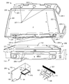
- FIG. 1 shows a conventional drive tray 120 that has two side walls 125 - 1 and 125 - 2 that extend in a direction normal (Y direction) to a plane defined by a planar bridge 130 (XZ plane).
- the bridge 130 has a thickness or thicknesses (Y direction) defined by side wall extensions 132 - 1 , 132 - 2 , 134 - 1 and 134 - 2 , which meet at a central square 138 , and a pair of braces 136 - 1 and 136 - 2 that support the extensions 132 - 1 and 134 - 1 and the extensions 132 - 2 and 134 - 2 , respectively.
- Other features include finger grips 126 - 1 and 126 - 2 as well as side wall tabs 129 - 1 and 129 - 2 .
- FIG. 1 also shows a conventional stack 100 of drive tray and drive assemblies formed by drive bodies 110 - 1 , 110 - 2 and 110 - 3 being seated in trays 120 - 1 , 120 - 2 and 120 - 3 , respectively.
- the bridges 130 - 1 , 130 - 2 and 130 - 3 are positioned adjacent respective bottom sides 114 - 1 , 114 - 2 and 114 - 3 of the drive bodies.
- a conventional tray physically mounts to opposing sides of a drive body where a bridge connects two side walls and runs along a surface of the drive.
- various arrows indicate fluid flow direction across and adjacent to the bottom sides 114 - 1 , 114 - 2 and 114 - 3 of the respective drive bodies 110 - 1 , 110 - 2 and 110 - 3 .
- fluid flow is impeded by each of the respective bridges 130 - 1 , 130 - 2 and 130 - 3 .
- the four extensions 132 - 1 , 132 - 2 , 134 - 1 and 134 - 2 , the central square 138 and the pair of braces 136 - 1 and 136 - 2 can all impede fluid flow.
- FIG. 2 shows an exemplary tray 220 with and without a drive body 110 .
- Orthogonal directions X, Y and Z are shown, for example, as being associated with widths, heights and lengths of the tray 220 and the drive body 110 .
- the tray 220 includes end members 221 and 222 (X direction) and side members 223 and 224 (Z direction), which, collectively, form a substantially rectangular frame 230 .
- Side walls 225 - 1 and 225 - 2 extend in a direction substantially normal (Y direction) to a plane defined by the frame 230 (XZ plane).
- each of the side walls 225 - 1 and 225 - 2 includes engagement features such as dampers 227 - 1 and 227 - 2 .
- Each damper may be made of a material having damping properties (e.g., rubber or other polymeric, suitable composite material, etc.).
- each damper includes one or more contact points for contacting a side of a drive body.
- a damper may have a “grippy” surface that provides a sufficient coefficient of friction to engage a side of a drive body where such a surface may be smooth or rough.
- the drive tray 220 includes the parallel side members 223 and 224 and at least one end member 221 and 222 connected to the side members 223 and 224 to collectively form a resilient, substantially rectangular frame 230 for receipt of a drive body.
- the pair of parallel side walls 225 - 1 and 225 - 2 extend in a direction normal (Y direction) to a plane defined by the frame 230 (XZ plane) and include engagement features 227 - 1 and 227 - 2 to engage opposing sides of a drive body (e.g., YZ sides of a drive body).
- the frame 230 is resilient to allow for receipt of a drive body between the side walls 225 - 1 and 225 - 2 .
- the frame 230 is configured to allow the side walls 225 - 1 and 225 - 2 to engage opposing sides of a drive body, which allows the dampers 227 - 1 and 227 - 2 to damp vibrations that could be transmitted from a housing to the tray 220 .
- Such an arrangement can also damp vibrations that could be transmitted from a drive body to the tray 220 .
- the frame 230 is not intended to interfere with the ability of engagement features to engage opposing sides of a drive body.
- FIG. 2 also shows an exemplary assembly 200 that includes a drive body 110 seated in the exemplary tray 220 .
- the drive body 110 has a top side 112 (e.g., XZ plane at an upper Y dimension) and a bottom side 114 (e.g., XZ plane at a lower Y dimension).
- the frame 230 is positioned intermediate the top side 112 and the bottom side 114 of the drive body 110 (see, e.g., the frame 230 height ⁇ Y, the upper edge of which may be set even with the top side 112 ).
- the frame 230 does not extend in the Z direction or the X direction over the top side 112 .
- a frame may extend a small amount in a direction normal to a top side of a drive body (e.g., along a fluid flow direction that would not have any significant impact on fluid flow across the top side of the drive body).
- the frame 230 includes a pair of arms near the aft end of the side walls 225 - 1 and 225 - 2 (see, e.g., dimensions Y 1 , Y 2 , Y 3 and Y 4 near the end member 221 ) where Y 1 is substantially aligned with a surface of the top side 112 of the drive body 110 and Y 3 is substantially aligned with another surface of the top side 112 of the drive body 110 .
- various drive bodies may have contoured or multilevel sides.
- an exemplary frame may be configured for alignment with one or more contours or levels of a top side of a drive body.
- FIG. 2 shows an exemplary assembly 250 that includes a housing 102 that houses a drive body 110 seated in a tray 220 .
- the drive body 110 includes one or more sockets 111 configured for receipt of one or more connectors 108 and 109 .
- the connector 108 may connect to control circuitry 106 , which may be associated with a motherboard 104 (e.g., computer motherboard with a chipset, memory, etc.).
- the member 221 of the frame 230 (marked in solid black) does not interfere with access to the one or more sockets 111 of the drive body 110 .
- FIG. 2 shows an exemplary assembly 250 that includes a housing 102 that houses a drive body 110 seated in a tray 220 .
- the drive body 110 includes one or more sockets 111 configured for receipt of one or more connectors 108 and 109 .
- the connector 108 may connect to control circuitry 106 , which may be associated with a motherboard 104 (e.g., computer motherboard with a chipset, memory
- an exemplary tray may not include an aft end member or may include a truncated aft end member that does not interfere with access to one or more sockets of a drive body (e.g., or optionally other drive features such as jumpers, etc.).
- an exemplary tray can include tool-less engagement features that capture a drive body and can include features that tool-lessly engage the tray with a bay or housing (see, e.g., features 228 - 1 and 228 - 2 ).
- Tool-less engagement features allow a user to readily install and remove a drive body from a housing, case, frame, etc.
- FIG. 3 shows various exemplary trays 310 , 320 , 330 and 340 .
- the tray 310 includes a fore end member but no aft end member to form a U-shaped, or substantially rectangular, frame (e.g., for positioning intermediate a top side and a bottom side of a drive body).
- the tray 320 includes a substantially rectangular frame formed by at least one truncated aft end member 321 - 1 and 321 - 2 , which can assist with removal of a drive body and drive tray assembly, for example, to help ensure, upon sliding the assembly out of a bay, that the drive body remains seated in the drive tray.
- the tray 330 includes an aft end member but no fore end member to form a U-shaped, or substantially rectangular, frame (e.g., for positioning intermediate a top side and a bottom side of a drive body).
- the tray 340 includes a substantially rectangular frame formed by at least one truncated fore end member 342 - 1 and 342 - 2 , which can assist with insertion of a drive body and drive tray assembly, for example, to help ensure, upon sliding the assembly into a bay, that the drive body remains seated in the drive tray.
- the full end member of a frame (e.g., whether fore or aft) is configured with sufficient rigidity, for example, to allow the engagement features of the side walls to engage a drive body.
- an exemplary tray may include one truncated end member (e.g., of a width in the X direction that is less than the width of an opposing full end member).
- FIG. 4 shows an exemplary stack 400 of five drive body and drive tray assemblies: 110 - 1 and 220 - 1 , 110 - 2 and 220 - 2 , 110 - 3 and 220 - 3 , 110 - 4 and 220 - 4 , and 110 - 5 and 220 - 5 .
- gaps exist between adjacent assemblies in the Y direction where fluid flow in these gaps is shown as being unimpeded in the Z direction.
- fluid flow in the Z direction is impeded by the bridges 130 - 1 , 130 - 2 and 130 - 3 .
- an exemplary tray e.g., when compared to the conventional tray 120 ), can enhance natural convection.
- FIG. 5 shows a heat transfer diagram 520 , a heat transfer equation 530 and an approximate plot of axial velocity versus axial dimension 540 .
- heat is transferred from a drive N and a drive N+1 to cooling fluid flowing in a gap, the fluid flowing predominantly along the Z direction.
- the flux of energy ( ⁇ Q/ ⁇ t) is equal to the heat transfer coefficient for a plate (h plate ), the area of the plate (A) and the temperature difference between the plate and the cooling fluid (T plate ⁇ T in ).
- Heat transfer may optionally be characterized by Reynolds number (ratio of inertial forces to viscous forces), Prandtl number (ratio of kinematic viscosity and thermal diffusivity), Nusselt number (ratio of convective to conductive heat transfer across a surface) or Grashof number (ratio of the buoyancy to viscous force acting on a fluid).
- the plot 540 shows approximate axial velocities versus axial distance (e.g., Z direction) for fluid flowing adjacent a drive body seated in a conventional tray (see, e.g., FIG. 1 ) and an exemplary tray (see, e.g., FIG. 2 or FIG. 3 ).
- an exemplary tray can increase heat transfer coefficient (h plate 1) compared to a conventional tray (h plate 2). Heat transfer depends on various factors. Where obstructions to flow exist (solid blocks in the plot 540 ), flow is impeded, which diminishes momentum and typically velocity (e.g., for constant cross-sectional flow area). Accordingly, an exemplary tray allows for unimpeded flow and enhancement of flux of energy from a drive body to a cooling fluid.
- FIG. 6 shows an exemplary system 600 that was used to conduct performance trials for three exemplary drive and tray assemblies 110 - 1 and 220 - 1 (upper), 110 - 2 and 220 - 2 (middle) and 110 - 3 and 220 - 3 (lower) located in a housing 102 .
- the housing 102 included an air mover (e.g., a fan) configured to drive air through openings 105 .
- an air mover e.g., a fan
- pressure inside the housing 102 is reduced, which draws air in via the gaps between and adjacent to the assemblies.
- a drive may be a HDD, a SDD, or other type of media drive.
- FIG. 6 also shows a plot 640 of temperatures measured with respect to time for the exemplary system 600 (solid lines) and for a conventional system that relied on conventional trays as shown in FIG. 1 (dashed lines).
- the system 600 with the exemplary trays reduced temperatures in the gaps.
- the middle assembly drive body 110 - 2 and tray 220 - 2
- the reduction in temperature was over two degrees Celsius. Accordingly, where a stack includes three or more exemplary drive and drive tray assemblies, middle drives may be expected to have significantly increased heat transfer compared to conventional drive and drive tray assemblies.
- a computer manufacturer may choose to alter specifications for an air mover such as a fan based on use of one or more exemplary trays. Such a decision may reduce energy usage of the computer.
- a controller may sense temperature and actuate an air mover responsive to an increase in temperature. Where exemplary trays are used, the air mover may reduce the temperature more quickly (compared to conventional tray usage) and allow for shorter actuation periods for the air mover, which, in turn, can reduce energy usage.
- operation of a system may simply act to reduce temperature of one or more drives, which, in turn, may extend the operational lifetime of the one or more drives.
- an exemplary tray provides an open, unimpeded volumetric space adjacent a side of a drive body. Where three or more drive body and drive tray assemblies are stacked, use of exemplary trays allows open volumetric spaces above and below middle drives as the exemplary trays do not introduce any blockage between the drives.
- an assembly includes a rectangular drive body that has a top side, a bottom side and four side walls and a drive tray that includes a resilient frame configured for receipt of the drive body intermediate the top side and the bottom side and a pair of parallel side walls with dampers configured to contact two of the four side walls of the drive body and to damp vibrations between the drive tray and the drive body.
- An assembly may include additional components, for example, the foregoing assembly may include a second rectangular drive body and a second drive tray where the second drive body is received by the second drive trays.
- components may be arranged in a stack with an air flow channel between adjacent drive bodies where the air flow channel is unimpeded by the frames of the drive trays.
- a drive body may be defined by a length and a width where the product of the length and the width approximates a heat transfer surface area for the drive body and where the heat transfer surface defines a boundary of an air flow channel unimpeded by a frame of a drive tray.
- An exemplary system may includes a stack formed by one or more drive body and drive tray assemblies and an air mover configured to draw air into one or more air flow channel between adjacent assemblies.
- a system may include a housing to house the stack and the air mover. Further, such a housing may include two or more drive bays configured for receipt of the drive bodies (e.g., as received by the drive trays).
- An exemplary tray may include rails along parallel side walls that are configured for receipt by a drive bay (e.g., of a housing).
- FIG. 7 shows an exemplary method 700 for removing heat from a system that includes one or more drive and drive tray assemblies.
- the method 700 includes providing a housing that includes adjacent drive bays, each drive bay holding a rectangular drive body disposed intermediate a top side and a bottom side in a resilient, substantially rectangular frame of a slidably removable drive tray.
- the method 700 includes electrically or electrically and mechanically operating one or more components housed in at least one of the drive bodies. As such operating generates heat, the method 700 includes a heat removal block 730 that draws air into the housing.
- an exemplary method may draw in air by an air mover such as a fan that expels air from a housing.
- an exemplary method may include sensing a temperature and drawing air responsive to the sensing, for example, where the sensing senses temperature in at least one air flow channel.
- a drive body may be defined by a length and a width where the product of the length and the width approximates a heat transfer surface area for the drive body.
- one or more channels may be defined in part by a heat transfer surface of a respective one of the drive bodies.
Abstract
Description
Claims (18)
Priority Applications (1)
| Application Number | Priority Date | Filing Date | Title |
|---|---|---|---|
| US12/729,430 US9330730B2 (en) | 2010-03-23 | 2010-03-23 | Drive tray |
Applications Claiming Priority (1)
| Application Number | Priority Date | Filing Date | Title |
|---|---|---|---|
| US12/729,430 US9330730B2 (en) | 2010-03-23 | 2010-03-23 | Drive tray |
Publications (2)
| Publication Number | Publication Date |
|---|---|
| US20110234064A1 US20110234064A1 (en) | 2011-09-29 |
| US9330730B2 true US9330730B2 (en) | 2016-05-03 |
Family
ID=44655577
Family Applications (1)
| Application Number | Title | Priority Date | Filing Date |
|---|---|---|---|
| US12/729,430 Active 2034-04-30 US9330730B2 (en) | 2010-03-23 | 2010-03-23 | Drive tray |
Country Status (1)
| Country | Link |
|---|---|
| US (1) | US9330730B2 (en) |
Cited By (4)
| Publication number | Priority date | Publication date | Assignee | Title |
|---|---|---|---|---|
| US9530466B1 (en) * | 2014-01-14 | 2016-12-27 | Marvell International Llc. | System and method for memory access dynamic mode switching |
| US20180137895A1 (en) * | 2016-11-15 | 2018-05-17 | Freebox | Support for computer data back-up unit(s) |
| US10936025B2 (en) * | 2019-04-08 | 2021-03-02 | Hongfujin Precision Electronics (Tianjin) Co., Ltd. | Fixing bracket for the installion of computer expansion card |
| US11029736B2 (en) * | 2018-08-01 | 2021-06-08 | Lenovo Enterprise Solutions (Singapore) Pte. Ltd. | Support apparatus |
Families Citing this family (5)
| Publication number | Priority date | Publication date | Assignee | Title |
|---|---|---|---|---|
| US9330730B2 (en) * | 2010-03-23 | 2016-05-03 | Lenovo (Singapore) Pte. Ltd. | Drive tray |
| CN104375595B (en) * | 2014-11-10 | 2017-09-19 | 英业达科技有限公司 | A kind of tool-free installation hard disk unit |
| US9615466B2 (en) * | 2015-07-30 | 2017-04-04 | Quanta Computer Inc. | Tool less component carrier |
| US9861011B1 (en) | 2016-06-22 | 2018-01-02 | HGST Netherlands B.V. | Stackable sleds for storing electronic devices |
| DE102018108977A1 (en) * | 2018-04-16 | 2019-10-17 | Paul Hettich Gmbh & Co. Kg | Shelf for a furniture or household appliance, furniture and household appliance |
Citations (68)
| Publication number | Priority date | Publication date | Assignee | Title |
|---|---|---|---|---|
| US5921644A (en) * | 1996-10-03 | 1999-07-13 | Hewlett-Packard Company | Mounting arrangement for mounting either of two differently-sized subsystem units |
| US6067225A (en) * | 1997-08-04 | 2000-05-23 | Sun Microsystems, Inc. | Disk drive bracket |
| US6166900A (en) * | 1997-12-15 | 2000-12-26 | Lsi Logic Corporation | Media drive canister vibration dampner and method of dampening |
| US6227630B1 (en) * | 1998-04-08 | 2001-05-08 | International Business Machines Corporation | Accessory mounting for digital computer |
| US6231224B1 (en) * | 1999-09-22 | 2001-05-15 | International Business Machines Corporation | Light pipe guide and carrier for hard disk drive |
| US6233143B1 (en) * | 1999-09-22 | 2001-05-15 | International Business Machines Corporation | Shock dampening system for hard disk drive carrier |
| US6259599B1 (en) * | 1999-03-23 | 2001-07-10 | International Business Machines Corporation | Shock absorbing feet for a disk drive carrier or other computer sub-system housing |
| US6385036B1 (en) * | 1999-09-10 | 2002-05-07 | Robert C. Chien | Screwless computer case assembly |
| US20020101713A1 (en) * | 2001-01-31 | 2002-08-01 | Eland Michael P. | Computer peripheral mounting bracket |
| US20020199048A1 (en) * | 1999-05-11 | 2002-12-26 | Josef Rabinovitz | Enclosure for computer peripheral devices |
| US20040022034A1 (en) * | 2001-11-28 | 2004-02-05 | Coles Henry C. | Low profile latch activator |
| US6719385B1 (en) * | 2000-01-14 | 2004-04-13 | International Business Machines Corporation | System for holding a device in a computer system |
| US20040095716A1 (en) * | 2002-11-14 | 2004-05-20 | Dell Computer Corporation | Hard drive carrier |
| US20040100761A1 (en) * | 2002-11-21 | 2004-05-27 | Dana Liu | Rotatable mechanism of removable computer peripheral device |
| US20040264121A1 (en) * | 2001-08-29 | 2004-12-30 | Orriss David J | Mounting for disk drive unit and method of handling |
| US6850410B2 (en) * | 2001-06-29 | 2005-02-01 | Emc Corporation | Advanced technology attachment disk drive module with fibre channel system characteristics |
| US20050024819A1 (en) * | 2003-07-30 | 2005-02-03 | Wen-Tang Peng | Mounting mechanism for storage device |
| US6918174B2 (en) * | 2002-10-21 | 2005-07-19 | Sun Microsystems, Inc. | Tool-less modular removable hard disk drive (HDD) apparatus |
| US20050174730A1 (en) * | 2004-02-05 | 2005-08-11 | Chao-Jung Chen | Vibration-proof removable module |
| US20060023413A1 (en) * | 2004-07-30 | 2006-02-02 | Dell Products L.P. | Method and apparatus for installing a component in an information handling system |
| US7079381B2 (en) * | 2004-01-07 | 2006-07-18 | International Business Machines Corporation | System and method for aligning and supporting interconnect systems |
| US7088579B1 (en) * | 2003-11-13 | 2006-08-08 | Storage Technology Corporation | Small form factor disk drive carrier |
| US20060268509A1 (en) * | 2005-05-31 | 2006-11-30 | Dell Products L.P. | Apparatus and method for securing a component in an information handling system |
| US20070053154A1 (en) * | 2005-09-02 | 2007-03-08 | Hitachi, Ltd. | Disk array apparatus |
| US20070127202A1 (en) * | 2005-12-01 | 2007-06-07 | Xyratex Technology Limited | Data storage device carrier and carrier tray |
| US20070159786A1 (en) * | 2006-01-11 | 2007-07-12 | Kuo-Kuang Liu | Removable hard disk housing assembly |
| US7251099B2 (en) * | 2003-12-22 | 2007-07-31 | Quanta Computer Inc. | Hard disk drive tray structure with flex circuit extending between exposed sides and connected to metal pad and indicator |
| US7271999B2 (en) * | 1999-05-11 | 2007-09-18 | Josef Rabinovitz | Enclosure for computer peripheral devices |
| US20070217143A1 (en) * | 2006-03-20 | 2007-09-20 | International Business Machines Corporation | Hard disk enclosure blade |
| US20070230107A1 (en) * | 2006-03-30 | 2007-10-04 | Inventec Corporation | Removable device |
| US7312999B1 (en) * | 2005-04-29 | 2007-12-25 | Network Appliance, Inc. | High density drive chassis assembly |
| US7319586B2 (en) * | 2003-12-29 | 2008-01-15 | Sherwood Information Partners, Inc. | Disk-drive enclosure having drives in a herringbone pattern to improve airflow and method |
| US7324349B2 (en) * | 2005-04-26 | 2008-01-29 | Dell Products L.P. | Method and apparatus for coupling a modular component to a chassis |
| US20080060363A1 (en) * | 2006-09-08 | 2008-03-13 | Martin Joseph Crippen | Air re-cool for electronic equipment |
| US20080080130A1 (en) * | 2006-10-03 | 2008-04-03 | Chen Gracie L | Quick plug/eject concept SATA hard disk drive rack |
| US20080128579A1 (en) * | 2006-12-01 | 2008-06-05 | Hon Hai Precision Industry Co., Ltd. | Mounting apparatus for disk drive |
| US20080158810A1 (en) * | 2006-12-29 | 2008-07-03 | Universal Scientific Industrial Co., Ltd. | Hard disk drive drawer |
| US20080204994A1 (en) * | 2007-02-23 | 2008-08-28 | D-Link Corporation | Hard disk tray |
| US20080259554A1 (en) * | 2007-04-17 | 2008-10-23 | Hong Fu Jin Precision Industry (Shenzhen) Co., Ltd. | Mounting apparatus for storage device |
| US7483268B1 (en) * | 2006-09-28 | 2009-01-27 | Emc Corporation | Disk drive carrier |
| US7492586B2 (en) * | 2007-05-11 | 2009-02-17 | Hong Fu Jin Precision Industry (Shenzhen) Co., Ltd. | Fixing apparatus for hard disk drive |
| US7495904B2 (en) * | 2005-07-06 | 2009-02-24 | Hong Fu Jin Precision Industry (Shen Zhen) Co., Ltd. | Fixing apparatus of data storage device |
| US20090091884A1 (en) * | 2007-10-05 | 2009-04-09 | Jabil Circuit, Inc. | Storage device carrier |
| US7542295B2 (en) * | 2006-04-21 | 2009-06-02 | Maxvision Corporation | Removable hard drive module for a computer |
| US7570484B1 (en) * | 2006-10-30 | 2009-08-04 | American Megatrends, Inc. | System and apparatus for removably mounting hard disk drives |
| US7609511B2 (en) * | 2007-08-30 | 2009-10-27 | Hong Fu Jin Precision Industry (Shenzhen) Co., Ltd. | Fixing apparatus for hard disk drive |
| US7626812B2 (en) * | 2008-01-31 | 2009-12-01 | Sercomm Corporation | Removable hard-disk structure without screws |
| US20090296338A1 (en) * | 2008-05-30 | 2009-12-03 | Hong Fu Jin Precision Industry(Shenzhen) Co., Ltd. | Mounting apparatus for data storage device |
| US7639492B2 (en) * | 2007-04-27 | 2009-12-29 | Hewlett-Packard Development Company, L.P. | Drive carrier for computer systems |
| US7679896B2 (en) * | 2006-10-11 | 2010-03-16 | Hong Fu Jin Precision Industry (Shenzhen) Co., Ltd. | Fixing apparatus for data storage device |
| US7697278B2 (en) * | 2007-10-11 | 2010-04-13 | Hong Fu Jin Precision Industry (Shenzhen) Co., Ltd. | Fixing apparatus for hard disk drive |
| US7697276B2 (en) * | 2007-10-11 | 2010-04-13 | Hong Fu Jin Precision Industry (Shenzhen) Co., Ltd. | Fixing apparatus for hard disk drive |
| US7729110B2 (en) * | 2007-11-15 | 2010-06-01 | Hong Fu Jin Precision Industry (Shenzhen) Co., Ltd. | Fixing apparatus for hard disk drive |
| US20100200523A1 (en) * | 2009-02-09 | 2010-08-12 | Dell Products L.P. | Tool-less Rack Mounting Apparatus and Systems |
| US7835148B2 (en) * | 2008-05-29 | 2010-11-16 | Wistron Corporation | Portable storage device capable of being disassembled easily |
| US20100321879A1 (en) * | 2009-06-19 | 2010-12-23 | Hong Fu Jin Precision Industry(Shenzhen) Co., Ltd. | Hard disk drive holder |
| US7950752B2 (en) * | 2006-05-19 | 2011-05-31 | Asustek Computer Inc. | Electronic device and case thereof |
| US7974088B2 (en) * | 2009-06-08 | 2011-07-05 | Hong Fu Jin Precision Industry (Shenzhen) Co., Ltd. | Retaining apparatus for data storage device |
| US20110188195A1 (en) * | 2008-09-02 | 2011-08-04 | Tanja Scherf-Smith | Customer replaceable unit drive isolator |
| US7995337B2 (en) * | 2007-02-16 | 2011-08-09 | Acer Inc. | Shock-absorbing structure for storage apparatus |
| US20110234064A1 (en) * | 2010-03-23 | 2011-09-29 | Makley Albert V | Drive Tray |
| US8159817B2 (en) * | 2009-07-24 | 2012-04-17 | Wistron Corporation | Slide rail mechanism and hard disk device having the slide rail mechanism |
| US8218315B2 (en) * | 2009-04-25 | 2012-07-10 | Hon Hai Precision Industry Co., Ltd. | Mounting apparatus for storage device |
| US8226050B2 (en) * | 2010-12-24 | 2012-07-24 | Hong Fu Jin Precision Industry (Shenzhen) Co., Ltd. | Clamping device for hard disk drive |
| US8264833B2 (en) * | 2009-12-01 | 2012-09-11 | Hon Hai Precision Industry Co., Ltd. | Anti-vibration hard disk drive assembly |
| US8405971B2 (en) * | 2007-12-18 | 2013-03-26 | Teradyne, Inc. | Disk drive transport, clamping and testing |
| US8456832B1 (en) * | 2009-12-22 | 2013-06-04 | Emc Corporation | Data storage drive carrier |
| US8544801B2 (en) * | 2011-07-21 | 2013-10-01 | Hon Hai Precision Industry Co., Ltd. | Bracket assembly for disk drive |
-
2010
- 2010-03-23 US US12/729,430 patent/US9330730B2/en active Active
Patent Citations (75)
| Publication number | Priority date | Publication date | Assignee | Title |
|---|---|---|---|---|
| US5921644A (en) * | 1996-10-03 | 1999-07-13 | Hewlett-Packard Company | Mounting arrangement for mounting either of two differently-sized subsystem units |
| US6067225A (en) * | 1997-08-04 | 2000-05-23 | Sun Microsystems, Inc. | Disk drive bracket |
| US6166900A (en) * | 1997-12-15 | 2000-12-26 | Lsi Logic Corporation | Media drive canister vibration dampner and method of dampening |
| US6227630B1 (en) * | 1998-04-08 | 2001-05-08 | International Business Machines Corporation | Accessory mounting for digital computer |
| US6259599B1 (en) * | 1999-03-23 | 2001-07-10 | International Business Machines Corporation | Shock absorbing feet for a disk drive carrier or other computer sub-system housing |
| US20020199048A1 (en) * | 1999-05-11 | 2002-12-26 | Josef Rabinovitz | Enclosure for computer peripheral devices |
| US7271999B2 (en) * | 1999-05-11 | 2007-09-18 | Josef Rabinovitz | Enclosure for computer peripheral devices |
| US6906918B2 (en) * | 1999-05-11 | 2005-06-14 | Josef Rabinovitz | Enclosure for computer peripheral devices |
| US6385036B1 (en) * | 1999-09-10 | 2002-05-07 | Robert C. Chien | Screwless computer case assembly |
| US6233143B1 (en) * | 1999-09-22 | 2001-05-15 | International Business Machines Corporation | Shock dampening system for hard disk drive carrier |
| US6231224B1 (en) * | 1999-09-22 | 2001-05-15 | International Business Machines Corporation | Light pipe guide and carrier for hard disk drive |
| US6719385B1 (en) * | 2000-01-14 | 2004-04-13 | International Business Machines Corporation | System for holding a device in a computer system |
| US20020101713A1 (en) * | 2001-01-31 | 2002-08-01 | Eland Michael P. | Computer peripheral mounting bracket |
| US6850410B2 (en) * | 2001-06-29 | 2005-02-01 | Emc Corporation | Advanced technology attachment disk drive module with fibre channel system characteristics |
| US20040264121A1 (en) * | 2001-08-29 | 2004-12-30 | Orriss David J | Mounting for disk drive unit and method of handling |
| US7054150B2 (en) * | 2001-08-29 | 2006-05-30 | Xyratex Technology Limited | Mounting for disk drive unit and method of handling |
| US20040022034A1 (en) * | 2001-11-28 | 2004-02-05 | Coles Henry C. | Low profile latch activator |
| US6918174B2 (en) * | 2002-10-21 | 2005-07-19 | Sun Microsystems, Inc. | Tool-less modular removable hard disk drive (HDD) apparatus |
| US20040095716A1 (en) * | 2002-11-14 | 2004-05-20 | Dell Computer Corporation | Hard drive carrier |
| US20040100761A1 (en) * | 2002-11-21 | 2004-05-27 | Dana Liu | Rotatable mechanism of removable computer peripheral device |
| US7072177B2 (en) * | 2003-07-30 | 2006-07-04 | Hong Fu Jin Precision Ind. (Shenzhen) Co., Ltd. | Mounting mechanism for storage device |
| US20050024819A1 (en) * | 2003-07-30 | 2005-02-03 | Wen-Tang Peng | Mounting mechanism for storage device |
| US7088579B1 (en) * | 2003-11-13 | 2006-08-08 | Storage Technology Corporation | Small form factor disk drive carrier |
| US7251099B2 (en) * | 2003-12-22 | 2007-07-31 | Quanta Computer Inc. | Hard disk drive tray structure with flex circuit extending between exposed sides and connected to metal pad and indicator |
| US7319586B2 (en) * | 2003-12-29 | 2008-01-15 | Sherwood Information Partners, Inc. | Disk-drive enclosure having drives in a herringbone pattern to improve airflow and method |
| US7079381B2 (en) * | 2004-01-07 | 2006-07-18 | International Business Machines Corporation | System and method for aligning and supporting interconnect systems |
| US20050174730A1 (en) * | 2004-02-05 | 2005-08-11 | Chao-Jung Chen | Vibration-proof removable module |
| US7092250B2 (en) * | 2004-02-05 | 2006-08-15 | Quanta Computer, Inc. | Vibration-proof removable module |
| US20060023413A1 (en) * | 2004-07-30 | 2006-02-02 | Dell Products L.P. | Method and apparatus for installing a component in an information handling system |
| US7457110B2 (en) * | 2004-07-30 | 2008-11-25 | Dell Products L.P. | Method and apparatus for installing a component in an information handling system |
| US7324349B2 (en) * | 2005-04-26 | 2008-01-29 | Dell Products L.P. | Method and apparatus for coupling a modular component to a chassis |
| US7312999B1 (en) * | 2005-04-29 | 2007-12-25 | Network Appliance, Inc. | High density drive chassis assembly |
| US20060268509A1 (en) * | 2005-05-31 | 2006-11-30 | Dell Products L.P. | Apparatus and method for securing a component in an information handling system |
| US7495904B2 (en) * | 2005-07-06 | 2009-02-24 | Hong Fu Jin Precision Industry (Shen Zhen) Co., Ltd. | Fixing apparatus of data storage device |
| US20070053154A1 (en) * | 2005-09-02 | 2007-03-08 | Hitachi, Ltd. | Disk array apparatus |
| US20070127202A1 (en) * | 2005-12-01 | 2007-06-07 | Xyratex Technology Limited | Data storage device carrier and carrier tray |
| US20070159786A1 (en) * | 2006-01-11 | 2007-07-12 | Kuo-Kuang Liu | Removable hard disk housing assembly |
| US20070217143A1 (en) * | 2006-03-20 | 2007-09-20 | International Business Machines Corporation | Hard disk enclosure blade |
| US20070230107A1 (en) * | 2006-03-30 | 2007-10-04 | Inventec Corporation | Removable device |
| US7542295B2 (en) * | 2006-04-21 | 2009-06-02 | Maxvision Corporation | Removable hard drive module for a computer |
| US7950752B2 (en) * | 2006-05-19 | 2011-05-31 | Asustek Computer Inc. | Electronic device and case thereof |
| US20080060363A1 (en) * | 2006-09-08 | 2008-03-13 | Martin Joseph Crippen | Air re-cool for electronic equipment |
| US7483268B1 (en) * | 2006-09-28 | 2009-01-27 | Emc Corporation | Disk drive carrier |
| US20080080130A1 (en) * | 2006-10-03 | 2008-04-03 | Chen Gracie L | Quick plug/eject concept SATA hard disk drive rack |
| US7379294B2 (en) * | 2006-10-03 | 2008-05-27 | Chen Gracie L | Quick plug/eject concept SATA hard disk drive rack |
| US7679896B2 (en) * | 2006-10-11 | 2010-03-16 | Hong Fu Jin Precision Industry (Shenzhen) Co., Ltd. | Fixing apparatus for data storage device |
| US7570484B1 (en) * | 2006-10-30 | 2009-08-04 | American Megatrends, Inc. | System and apparatus for removably mounting hard disk drives |
| US20080128579A1 (en) * | 2006-12-01 | 2008-06-05 | Hon Hai Precision Industry Co., Ltd. | Mounting apparatus for disk drive |
| US20080158810A1 (en) * | 2006-12-29 | 2008-07-03 | Universal Scientific Industrial Co., Ltd. | Hard disk drive drawer |
| US7995337B2 (en) * | 2007-02-16 | 2011-08-09 | Acer Inc. | Shock-absorbing structure for storage apparatus |
| US20080204994A1 (en) * | 2007-02-23 | 2008-08-28 | D-Link Corporation | Hard disk tray |
| US20080259554A1 (en) * | 2007-04-17 | 2008-10-23 | Hong Fu Jin Precision Industry (Shenzhen) Co., Ltd. | Mounting apparatus for storage device |
| US7639492B2 (en) * | 2007-04-27 | 2009-12-29 | Hewlett-Packard Development Company, L.P. | Drive carrier for computer systems |
| US7492586B2 (en) * | 2007-05-11 | 2009-02-17 | Hong Fu Jin Precision Industry (Shenzhen) Co., Ltd. | Fixing apparatus for hard disk drive |
| US7609511B2 (en) * | 2007-08-30 | 2009-10-27 | Hong Fu Jin Precision Industry (Shenzhen) Co., Ltd. | Fixing apparatus for hard disk drive |
| US20090091884A1 (en) * | 2007-10-05 | 2009-04-09 | Jabil Circuit, Inc. | Storage device carrier |
| US7697278B2 (en) * | 2007-10-11 | 2010-04-13 | Hong Fu Jin Precision Industry (Shenzhen) Co., Ltd. | Fixing apparatus for hard disk drive |
| US7697276B2 (en) * | 2007-10-11 | 2010-04-13 | Hong Fu Jin Precision Industry (Shenzhen) Co., Ltd. | Fixing apparatus for hard disk drive |
| US7729110B2 (en) * | 2007-11-15 | 2010-06-01 | Hong Fu Jin Precision Industry (Shenzhen) Co., Ltd. | Fixing apparatus for hard disk drive |
| US8405971B2 (en) * | 2007-12-18 | 2013-03-26 | Teradyne, Inc. | Disk drive transport, clamping and testing |
| US7626812B2 (en) * | 2008-01-31 | 2009-12-01 | Sercomm Corporation | Removable hard-disk structure without screws |
| US7835148B2 (en) * | 2008-05-29 | 2010-11-16 | Wistron Corporation | Portable storage device capable of being disassembled easily |
| US20090296338A1 (en) * | 2008-05-30 | 2009-12-03 | Hong Fu Jin Precision Industry(Shenzhen) Co., Ltd. | Mounting apparatus for data storage device |
| US20110188195A1 (en) * | 2008-09-02 | 2011-08-04 | Tanja Scherf-Smith | Customer replaceable unit drive isolator |
| US20100200523A1 (en) * | 2009-02-09 | 2010-08-12 | Dell Products L.P. | Tool-less Rack Mounting Apparatus and Systems |
| US8218315B2 (en) * | 2009-04-25 | 2012-07-10 | Hon Hai Precision Industry Co., Ltd. | Mounting apparatus for storage device |
| US7974088B2 (en) * | 2009-06-08 | 2011-07-05 | Hong Fu Jin Precision Industry (Shenzhen) Co., Ltd. | Retaining apparatus for data storage device |
| US7864522B1 (en) * | 2009-06-19 | 2011-01-04 | Hong Fu Jin Precision Industry (Shenzhen) Co., Ltd. | Hard disk drive holder |
| US20100321879A1 (en) * | 2009-06-19 | 2010-12-23 | Hong Fu Jin Precision Industry(Shenzhen) Co., Ltd. | Hard disk drive holder |
| US8159817B2 (en) * | 2009-07-24 | 2012-04-17 | Wistron Corporation | Slide rail mechanism and hard disk device having the slide rail mechanism |
| US8264833B2 (en) * | 2009-12-01 | 2012-09-11 | Hon Hai Precision Industry Co., Ltd. | Anti-vibration hard disk drive assembly |
| US8456832B1 (en) * | 2009-12-22 | 2013-06-04 | Emc Corporation | Data storage drive carrier |
| US20110234064A1 (en) * | 2010-03-23 | 2011-09-29 | Makley Albert V | Drive Tray |
| US8226050B2 (en) * | 2010-12-24 | 2012-07-24 | Hong Fu Jin Precision Industry (Shenzhen) Co., Ltd. | Clamping device for hard disk drive |
| US8544801B2 (en) * | 2011-07-21 | 2013-10-01 | Hon Hai Precision Industry Co., Ltd. | Bracket assembly for disk drive |
Non-Patent Citations (2)
| Title |
|---|
| CoolerMaster (http://www.hardwarecanucks.com/forum/hardware-canucks-reviews/11304-cooler-master-haf-932-case-review-10.html, Nov. 6, 2008, retrieved Mar. 19, 2015). * |
| SilverStone (http://hardwarecanucks.com/forum/hardware-canucks-reviews/12201-silverstone-fortress-ft01-mid-tower-casere-view-8.html, Dec. 1, 2008, retrieved Mar. 23, 2015). * |
Cited By (5)
| Publication number | Priority date | Publication date | Assignee | Title |
|---|---|---|---|---|
| US9530466B1 (en) * | 2014-01-14 | 2016-12-27 | Marvell International Llc. | System and method for memory access dynamic mode switching |
| US20180137895A1 (en) * | 2016-11-15 | 2018-05-17 | Freebox | Support for computer data back-up unit(s) |
| US10297288B2 (en) * | 2016-11-15 | 2019-05-21 | Freebox | Support for computer data back-up unit(s) |
| US11029736B2 (en) * | 2018-08-01 | 2021-06-08 | Lenovo Enterprise Solutions (Singapore) Pte. Ltd. | Support apparatus |
| US10936025B2 (en) * | 2019-04-08 | 2021-03-02 | Hongfujin Precision Electronics (Tianjin) Co., Ltd. | Fixing bracket for the installion of computer expansion card |
Also Published As
| Publication number | Publication date |
|---|---|
| US20110234064A1 (en) | 2011-09-29 |
Similar Documents
| Publication | Publication Date | Title |
|---|---|---|
| US9330730B2 (en) | Drive tray | |
| US10426060B2 (en) | Modular mass storage system | |
| TWI745137B (en) | Server system | |
| JP5296771B2 (en) | Computer system | |
| DK2503429T3 (en) | Vibration isolation of computer components | |
| US10462925B1 (en) | Mass storage device retainer assembly | |
| US9317081B2 (en) | Disk drive carriers and mountable hard drive systems with improved air flow | |
| US9443560B2 (en) | Server with storage drive cooling system | |
| US7660108B2 (en) | Apparatus for positioning electronic component modules within an equipment chassis | |
| US9448601B1 (en) | Modular mass storage system with controller | |
| US20140029193A1 (en) | Computer system cooling using an externally-applied fluid conduit | |
| US9485888B2 (en) | Cooling system for use in a mass storage chassis assembly | |
| US10042399B2 (en) | Hard drive assemblies | |
| US20190380229A1 (en) | Discrete cooling module | |
| US9723756B1 (en) | Rack mounting portion assembly | |
| US8199486B2 (en) | Server cabinet | |
| US8456839B2 (en) | Cooling structure for housing device | |
| US9921619B2 (en) | Method for containing computer system components | |
| CN107113995B (en) | Interlock bracket unit | |
| CN102207759A (en) | Fan bracket | |
| US8142149B2 (en) | Fan device and fan device assembly | |
| Herrlin et al. | Gravity-assisted air mixing in data centers and how it affects the rack cooling effectiveness | |
| US11910560B2 (en) | Crossbar and sled for a modular server and/or information handling system | |
| TWI414930B (en) | Computer system | |
| JP2010161282A (en) | Electronic equipment and electronic equipment storage rack |
Legal Events
| Date | Code | Title | Description |
|---|---|---|---|
| AS | Assignment |
Owner name: LENOYO (SINGAPORE) PT. LTD., SINGAPORE Free format text: ASSIGNMENT OF ASSIGNORS INTEREST;ASSIGNORS:MAKLEY, ALBERT V.;MARTIN-OTTO, WILLIAM F.;PAMLEY, MARC R.;AND OTHERS;SIGNING DATES FROM 20100316 TO 20100318;REEL/FRAME:024183/0543 |
|
| STCF | Information on status: patent grant |
Free format text: PATENTED CASE |
|
| AS | Assignment |
Owner name: LENOVO PC INTERNATIONAL LIMITED, HONG KONG Free format text: ASSIGNMENT OF ASSIGNORS INTEREST;ASSIGNOR:LENOVO (SINGAPORE) PTE. LTD.;REEL/FRAME:049688/0741 Effective date: 20160701 |
|
| MAFP | Maintenance fee payment |
Free format text: PAYMENT OF MAINTENANCE FEE, 4TH YEAR, LARGE ENTITY (ORIGINAL EVENT CODE: M1551); ENTITY STATUS OF PATENT OWNER: LARGE ENTITY Year of fee payment: 4 |
|
| MAFP | Maintenance fee payment |
Free format text: PAYMENT OF MAINTENANCE FEE, 8TH YEAR, LARGE ENTITY (ORIGINAL EVENT CODE: M1552); ENTITY STATUS OF PATENT OWNER: LARGE ENTITY Year of fee payment: 8 |