US9332969B2 - Fluid flow control apparatus and patient fluid sampling method - Google Patents
Fluid flow control apparatus and patient fluid sampling method Download PDFInfo
- Publication number
- US9332969B2 US9332969B2 US12/349,118 US34911809A US9332969B2 US 9332969 B2 US9332969 B2 US 9332969B2 US 34911809 A US34911809 A US 34911809A US 9332969 B2 US9332969 B2 US 9332969B2
- Authority
- US
- United States
- Prior art keywords
- housing
- port
- valve assembly
- fluid
- passageway
- Prior art date
- Legal status (The legal status is an assumption and is not a legal conclusion. Google has not performed a legal analysis and makes no representation as to the accuracy of the status listed.)
- Active, expires
Links
- 239000012530 fluid Substances 0.000 title claims abstract description 85
- 238000005070 sampling Methods 0.000 title claims abstract description 38
- 238000000034 method Methods 0.000 title claims description 15
- 230000008878 coupling Effects 0.000 claims abstract description 6
- 238000010168 coupling process Methods 0.000 claims abstract description 6
- 238000005859 coupling reaction Methods 0.000 claims abstract description 6
- 230000000717 retained effect Effects 0.000 claims 3
- 238000010276 construction Methods 0.000 description 4
- 239000000463 material Substances 0.000 description 3
- 210000004072 lung Anatomy 0.000 description 2
- 210000000056 organ Anatomy 0.000 description 2
- 230000000241 respiratory effect Effects 0.000 description 2
- 208000003322 Coinfection Diseases 0.000 description 1
- 230000006978 adaptation Effects 0.000 description 1
- 239000012620 biological material Substances 0.000 description 1
- 239000008280 blood Substances 0.000 description 1
- 210000004369 blood Anatomy 0.000 description 1
- 238000012790 confirmation Methods 0.000 description 1
- 238000011109 contamination Methods 0.000 description 1
- 238000011156 evaluation Methods 0.000 description 1
- 238000007373 indentation Methods 0.000 description 1
- 208000015181 infectious disease Diseases 0.000 description 1
- 239000007788 liquid Substances 0.000 description 1
- 230000007774 longterm Effects 0.000 description 1
- 238000004519 manufacturing process Methods 0.000 description 1
- 244000005700 microbiome Species 0.000 description 1
- 210000002345 respiratory system Anatomy 0.000 description 1
- 238000009423 ventilation Methods 0.000 description 1
Images


Classifications
-
- A—HUMAN NECESSITIES
- A61—MEDICAL OR VETERINARY SCIENCE; HYGIENE
- A61B—DIAGNOSIS; SURGERY; IDENTIFICATION
- A61B10/00—Other methods or instruments for diagnosis, e.g. instruments for taking a cell sample, for biopsy, for vaccination diagnosis; Sex determination; Ovulation-period determination; Throat striking implements
- A61B10/0096—Casings for storing test samples
-
- A—HUMAN NECESSITIES
- A61—MEDICAL OR VETERINARY SCIENCE; HYGIENE
- A61B—DIAGNOSIS; SURGERY; IDENTIFICATION
- A61B10/00—Other methods or instruments for diagnosis, e.g. instruments for taking a cell sample, for biopsy, for vaccination diagnosis; Sex determination; Ovulation-period determination; Throat striking implements
- A61B10/0045—Devices for taking samples of body liquids
-
- A61M1/0001—
-
- A—HUMAN NECESSITIES
- A61—MEDICAL OR VETERINARY SCIENCE; HYGIENE
- A61M—DEVICES FOR INTRODUCING MEDIA INTO, OR ONTO, THE BODY; DEVICES FOR TRANSDUCING BODY MEDIA OR FOR TAKING MEDIA FROM THE BODY; DEVICES FOR PRODUCING OR ENDING SLEEP OR STUPOR
- A61M1/00—Suction or pumping devices for medical purposes; Devices for carrying-off, for treatment of, or for carrying-over, body-liquids; Drainage systems
- A61M1/60—Containers for suction drainage, adapted to be used with an external suction source
-
- A—HUMAN NECESSITIES
- A61—MEDICAL OR VETERINARY SCIENCE; HYGIENE
- A61M—DEVICES FOR INTRODUCING MEDIA INTO, OR ONTO, THE BODY; DEVICES FOR TRANSDUCING BODY MEDIA OR FOR TAKING MEDIA FROM THE BODY; DEVICES FOR PRODUCING OR ENDING SLEEP OR STUPOR
- A61M39/00—Tubes, tube connectors, tube couplings, valves, access sites or the like, specially adapted for medical use
- A61M39/22—Valves or arrangement of valves
- A61M2039/229—Stopcocks
-
- A—HUMAN NECESSITIES
- A61—MEDICAL OR VETERINARY SCIENCE; HYGIENE
- A61M—DEVICES FOR INTRODUCING MEDIA INTO, OR ONTO, THE BODY; DEVICES FOR TRANSDUCING BODY MEDIA OR FOR TAKING MEDIA FROM THE BODY; DEVICES FOR PRODUCING OR ENDING SLEEP OR STUPOR
- A61M39/00—Tubes, tube connectors, tube couplings, valves, access sites or the like, specially adapted for medical use
- A61M39/22—Valves or arrangement of valves
- A61M39/223—Multiway valves
-
- F—MECHANICAL ENGINEERING; LIGHTING; HEATING; WEAPONS; BLASTING
- F16—ENGINEERING ELEMENTS AND UNITS; GENERAL MEASURES FOR PRODUCING AND MAINTAINING EFFECTIVE FUNCTIONING OF MACHINES OR INSTALLATIONS; THERMAL INSULATION IN GENERAL
- F16K—VALVES; TAPS; COCKS; ACTUATING-FLOATS; DEVICES FOR VENTING OR AERATING
- F16K11/00—Multiple-way valves, e.g. mixing valves; Pipe fittings incorporating such valves
- F16K11/02—Multiple-way valves, e.g. mixing valves; Pipe fittings incorporating such valves with all movable sealing faces moving as one unit
- F16K11/08—Multiple-way valves, e.g. mixing valves; Pipe fittings incorporating such valves with all movable sealing faces moving as one unit comprising only taps or cocks
- F16K11/083—Multiple-way valves, e.g. mixing valves; Pipe fittings incorporating such valves with all movable sealing faces moving as one unit comprising only taps or cocks with tapered plug
Definitions
- the present disclosure relates generally to patient specimen collection devices. More particularly, it relates to devices for collecting fluid samples from a patient's respiratory system and incorporating a fluid flow control apparatus having aspiration and instillation capabilities without a loss of internal pressure.
- Fluid sampling devices are commonly used to collect fluid samples from a patient's airway or other body cavities.
- the fluid sample may be subjected to laboratory testing or evaluation, therefore the integrity of the sample must be maintained during the sampling procedures. Additionally, it is often necessary to avoid secondary infection or contamination of other persons during the sampling procedure.
- a fluid is instilled into a patient's airway or other body cavity (e.g., via an intubated catheter), and then aspirated back (along with a specimen from the targeted area) into a sampling container.
- the fluid sample is then directed into a collection container in order that the sample may be examined for cells, micro organisms, blood or other biological material.
- a fluid flow control apparatus can be employed that enables the user to control the direction and/or amount of fluids transported in a given system or procedure.
- the majority of apparatuses used for this procedure are either separate apparatuses whereby, following instillation, the catheter or tube is exposed to room air and internal pressure is lost, or multiple stopcocks are required to accomplish the same functions.
- the apparatus includes a valve assembly comprising a body that defines a passageway, the body rotatably assembled to a housing along an axis of rotation, and at least two recesses defined by an interior surface of the housing and the body that are is formed separate from the passageway.
- the apparatus further including a first port and a second port, each extending from the housing and configured for connection to medical devices.
- valve assembly is operable to interchangeably align the passageway and the two recesses with the ports.
- the apparatus includes a cap connected to the housing that includes an opening for coupling to a specimen container.
- FIG. 1 is a side perspective view of a fluid sampling device according to aspects of the present disclosure
- FIG. 2 is a side perspective view of a fluid flow control apparatus in accordance with aspects of the present disclosure and useful with the device of FIG. 1 ;
- FIG. 3 is an exploded, cross-sectional view of the fluid flow control apparatus of FIG. 2 ;
- FIG. 4A is a cross-sectional view of the fluid flow control apparatus of FIG. 3 upon final assembly and in a first position;
- FIG. 4B is a cross-sectional view of the fluid flow control apparatus of FIG. 4B in a second position
- FIG. 5 is a top view of the fluid flow control apparatus of FIG. 2 ;
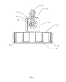
- FIG. 6 is a front view of the fluid sampling device of FIG. 1 in an instillation mode of operation
- FIG. 7 is a cross-sectional view of the fluid sampling device of FIG. 6 and illustrating an instillation flow path
- FIG. 8 is a front view of the fluid sampling device of FIG. 1 in an aspiration mode of operation
- FIG. 9 is a cross-sectional view of the fluid sampling device of FIG. 8 and illustrating an aspiration flow path.
- FIG. 10 illustrates use of the fluid sampling device of FIG. 1 in performing a medical specimen collection procedure.
- FIG. 1 One construction of a fluid sampling device 20 in accordance with the present disclosure is shown in FIG. 1 and includes a fluid flow control apparatus 22 and a specimen container 24 .
- the fluid flow control apparatus 22 includes a valve assembly 26 , first and second ports 28 , 30 , and a cap 32 . Details on the various components are provided below. In general terms, however, the fluid flow control apparatus 22 is selectively secured to the specimen container 24 .
- the valve assembly 26 operates to selectively fluidly connect the first and second ports 28 , 30 with each other and the specimen container 24 .
- the fluid sampling device 20 can be employed to obtain respiratory fluid samples or specimens from an intubated patient as part of a patient ventilation system, such as in conjunction with a bronchoalveolar lavage procedure, by instillating liquid into, and aspirating fluid specimens from, the patient.
- the valve assembly 26 includes a valve body 34 , a housing 36 , and a handle 38 .
- the valve body 34 is rotatably maintained by the housing 36 , with the handle 38 serving to allow a user to selectively alter a rotational position of the valve body 34 relative to the housing 36 .
- the valve assembly 26 is configured as a stopcock valve in some embodiments, although ball, gate or other suitable valves may be used.
- the valve body 34 includes or forms a base 40 , an intermediate section 42 , and a stem 44 .
- the base 40 has an exterior surface 46 along which opposing recesses or grooves 48 a , 48 b are defined.
- the intermediate section 42 extends from the base 40 , and forms a passageway 50 .
- the passageway 50 is fluidly open to an exterior of the intermediate section 42 at opposing, first and second ends 52 a , 52 b (best shown in FIG. 4B ). As shown, the passageway 50 is fluidly isolated from the recesses 48 a , 48 b .
- the passageway 50 can be described, in some embodiments, as being horizontal whereas the recesses 48 a , 48 b are vertical. Other constructions, however, are also acceptable.
- the stem 44 extends from the intermediate section 42 opposite the base 40 , and in some embodiments forms a circumferential rib 54 configured for rotatable assembly to the housing 36 , as described below.
- the housing 36 is sized to receive the valve body 34 , and can be integrally formed with the ports 28 , 30 and the cap 32 as shown. Regardless, the housing 36 includes or forms a lower portion 58 , an intermediate portion 60 , and an upper portion 62 .
- the upper portion 62 has a ridge 66 along which position indicators 64 are formed.
- the position indicators 64 are further illustrated in FIG. 2 and may be formed as touch-feel indicators or any other useful configuration. In one embodiment, the position indicators 64 project outward along the ridge 66 of the upper portion 62 .
- the position indicators 64 may be selectively formed as raised points or as raised elongated sections. Alternatively, the position indicators 64 may be selectively formed as grooves or recesses in the ridge 66 .
- the upper portion 62 also includes a channel 68 on an interior surface 70 of the housing 36 .
- the channel 68 may continuously extend around the perimeter of the interior surface 70 .
- the intermediate portion 60 extends from the upper portion 62 , in a direction opposite the ridge 66 , and forms opposing openings 72 a , 72 b .
- the lower portion 58 extends from the intermediate portion 60 .
- the handle 38 includes a directional end 74 , an opposing terminal end 78 , and a midpoint 76 .
- the directional end 74 includes a tang 80 .
- the tang 80 may be formed as a protrusion or extension on the directional end 74 .
- the midpoint 76 defines an axis of rotation that extends through the handle 38 and valve body 34 .
- the handle 38 can assume a variety of shapes conducive to convenient grasping by a user's hand/fingers.
- FIGS. 2 and 3 Connection of the handle 38 with the valve body 34 is shown in FIGS. 2 and 3 .
- the handle 38 provides a means for a medical personal to rotate the valve body 34 within the housing 36 of the valve assembly 26 .
- the handle 38 is aligned with the passageway 50 (i.e., a direction of extension of the handle 38 between the ends 74 , 78 corresponds with an axis of the passageway 50 ); in this manner, the orientation of the handle 38 provides confirmation to a user in aligning the passageway 50 relative to the ports 28 , 30 .
- a relationship of the tang 80 of the handle 38 and the position indicators 64 is further reflected in the view of FIG. 2 .
- the tang 80 of the handle 38 interacts with the position indicators 64 on the ridge 66 on the upper portion 62 of the housing 36 as the handle 38 is turned.
- the position indicator 64 consists of a pair of closely positioned molded protrusions, formed such that the tang 80 may rest comfortably between the protrusions and may also move past them.
- the position indicators 64 may also be formed to prevent further rotation of the handle 38 in a certain direction by protruding a sufficient distance above the ridge 66 to interfere with further movement of the tang 80 in that direction.
- the positions of the position indicators 64 correspond to the desired positions of the valve body 34 useful in patient fluid sampling.
- the valve body 34 rotates within the housing 36 of the valve assembly 26 .
- the housing 36 is configured to enclose the working components of the valve body 34 .
- a relationship of the channel 68 of the housing 36 and the rib 54 of the valve body 34 is further reflected in the views of FIGS. 4A and 4B .
- the channel 68 serves as a path within which the rib 54 rotates and serves to rotatably secure the valve body 34 within the housing 36 .
- the rib 54 /channel 68 interface is configured to provide a consistent, long term seal and leak tight fit.
- the exterior surface 46 of the valve body 34 maintains a fluidly sealed relationship with the interior surface 70 of the housing 36 .
- Other mounting relationships of the valve body 34 within the housing 36 are also equally acceptable.
- the passageway 50 and recesses 48 a , 48 b are sized and defined within the valve body 34 such that they correspond with openings 72 a , 72 b when aligned.
- the recesses 48 a , 48 b are aligned with the openings 72 a , 72 b of the housing 36 .
- the openings 72 a , 72 b of the housing 36 are aligned with the passageway 50 of the valve body 34 through reorientation of the valve body 34 when the handle 38 is turned (i.e., transitioned from the position or state of FIG. 4A to the position or state of FIG. 4B ).
- the first and second ports 28 , 30 are attached to the valve assembly 26 , mounted substantially opposite one another along the housing 36 .
- the ports 28 , 30 can be integrally formed with or by the housing 36 .
- the ports 28 , 30 can be formed separately and later assembled to the housing 26 .
- the ports 28 , 30 are structural bodies forming passageway 84 a , 84 b with inlet ends 86 a , 86 b and outlet ends 88 a , 88 b , respectively.
- the inlet end 86 a of the port 28 may be formed with exterior barbs 90 , as shown in FIG. 2 .
- the inlet end 86 b of the port 30 may be formed recessed threading 92 .
- the ports 28 , 30 may be female and male fittings and additionally may be luer fittings or any other suitable fitting type.
- the second port 30 is suitable for connection to a catheter or other tube or apparatus suitable for placement and connection within a patient's bodily cavity (e.g., lung) or organ.
- the first port 28 is suitable to connect and disconnect to various medial devices without removal of the catheter (or other component) from the second port 30 .
- the ports 28 , 30 are configured to facilitate coupling with a flexible tube, catheter or other medical device which can be received, and connection maintained, with the ports 28 , 30 .
- the cap 32 includes a top 94 and a perimeter 96 extending from the top 94 of the cap 32 at a length necessary to provide sealable engagement with the fluid sampling container 24 ( FIG. 1 ) as described below.
- the perimeter 96 includes indentations 98 for ease of handling by medical personnel. Additionally, the perimeter 96 may include flanges 100 to assist with handling.
- the perimeter 96 also includes a threaded interior surface 102 that correspond with a threaded exterior (not shown) of the fluid sampling container 24 , although other assembly techniques (e.g., snap-fit) are also acceptable.
- the top 94 forms an opening 104 through which a fluid connection between an interior of the housing 36 and a chamber 105 of the cap 32 is established.
- the cap 32 may be constructed of the same material as the housing 36 , or other suitably compatible material.
- the cap 32 may be formed integrally with the housing 36 , or attached later in the production process of the fluid flow control apparatus 22 .
- valve assembly 26 is sealed into the cap 32 such that the passageway 50 of the valve assembly 26 can be oriented and fluidly connected to the cap 32 as needed for the desired medical procedure.
- the opening 104 of the cap 32 has a diameter corresponding with the dimensional attributes of the interior surface 70 of the housing 36 to ensure a desired arrangement of the valve body 34 relative to the cap 32 upon final assembly.
- additional components useful in establishing and maintaining the desired fluid connection such as a coupling, a seal, etc. may be included.
- the valve assembly 26 may also be either formed integrally with, or appropriately sealed, to the ports 28 , 30 .
- the specimen container 24 may be any standard container used for specimen sampling purposes.
- the specimen container 24 may be clear or translucent in color and may also include volume indicators along the side.
- the specimen container 24 may be constructed of a plastic or any other suitable material.
- container 24 includes a threaded exterior portion that selectively engages with the threaded interior surface 102 ( FIG. 3 ) of the cap 32 for a sealed connection.
- the fluid sampling device 20 includes the valve assembly 26 with at least two positions, and may include four positions, to facilitate sampling of a patient's fluids.
- the position indicators 64 may consist of point positions, for example when the valve assembly 26 is in an aspiration or instillation position, or elongated indicators as when the valve assembly 26 is in a sealed position.
- the passageway 50 of the valve body 34 is aligned with the ports 28 , 30 such that the ports 28 , 30 are fluidly connected to one another.
- a resultant inspiration fluid flow path I represented by arrows in FIG. 7 , is configured for the instillation procedure.
- the passageway 50 is connected through the openings 72 a , 72 b in the housing 36 to each of the respective ports 28 , 30 in order to provide a path for fluids during instillation of the patient. In this position, no fluids or specimens may pass out of or into the container 24 ( FIG. 1 ).
- the specimen container 24 need not be connected to the fluid flow control apparatus 22 in the inspiration position or mode; however, the specimen container 24 may be connected without affecting the instillation procedure. Fluid may thus be injected with a syringe or other similar apparatus, down a tube or catheter into the lungs or other body cavities/organ. In this manner, fluid flow is directly from a fluid source, through the fluid flow control apparatus 22 , and into a patient or suction apparatus.
- the first and second ports 28 , 30 are fluidly connected to the specimen container 24 , as illustrated in FIGS. 8 and 9 .
- the valve body 34 is oriented such that the passageway 50 is blocked by the housing 36 and does not connect to the ports 28 , 30 .
- aspiration can occur and fluid samples may be drawn into the specimen container 24 attached to the cap 32 with negative pressure by using a suction means attached to the first port 28 .
- a resultant aspiration fluid flow path A (represented by arrows in FIG.
- the second port 30 is connected to tubing 112 that in turn is fluidly connected to an endotrachael tube or a tracheostomy tube; alternatively, the artificial airway 112 can be directly connected to the second port 30 .
- the second port 26 is configured for fluid connection to the artificial airway 112 otherwise establishing a direct connection to the patient's respiratory track 116 . In this manner, specimens may be collected.
- a third position of the fluid flow control apparatus 22 when available, is located between the instillation and aspiration positions described above.
- the third position is a paused position. In this position, the ports 28 , 30 are blocked and pressure to the catheters 112 is maintained in order that additional fluid or vacuum can be prepared for attachment to the first port 28 .
- a fourth position is available beyond the aspiration position, whereby the ports 28 , 30 are sealed (i.e., fluidly disconnected from the passageway 50 and the recesses 48 a , 48 b ) for sending the collected specimen for analysis.
Abstract
Description
Claims (16)
Priority Applications (11)
| Application Number | Priority Date | Filing Date | Title |
|---|---|---|---|
| US12/349,118 US9332969B2 (en) | 2009-01-06 | 2009-01-06 | Fluid flow control apparatus and patient fluid sampling method |
| AU2009335668A AU2009335668A1 (en) | 2009-01-06 | 2009-12-22 | Fluid flow control apparatus and patient fluid sampling method |
| RU2011133083/14A RU2526261C2 (en) | 2009-01-06 | 2009-12-22 | Fluid movement control unit and method for patient's fluid sampling |
| EP09775522.7A EP2391274B1 (en) | 2009-01-06 | 2009-12-22 | Fluid flow control apparatus |
| PCT/US2009/069152 WO2010080648A1 (en) | 2009-01-06 | 2009-12-22 | Fluid flow control apparatus and patient fluid sampling method |
| JP2011544497A JP5628206B2 (en) | 2009-01-06 | 2009-12-22 | Flow path control device used for medical fluid sampling |
| CN200980153895XA CN102271590B (en) | 2009-01-06 | 2009-12-22 | Fluid flow control apparatus and patient fluid sampling method |
| CA2750183A CA2750183C (en) | 2009-01-06 | 2009-12-22 | Fluid flow control apparatus and patient fluid sampling method |
| BRPI0923935A BRPI0923935A2 (en) | 2009-01-06 | 2009-12-22 | fluid flow control apparatus and patient fluid sampling method |
| KR1020117018378A KR101612584B1 (en) | 2009-01-06 | 2009-12-22 | Fluid flow control apparatus and patient fluid sampling method |
| MX2011007286A MX2011007286A (en) | 2009-01-06 | 2009-12-22 | Fluid flow control apparatus and patient fluid sampling method. |
Applications Claiming Priority (1)
| Application Number | Priority Date | Filing Date | Title |
|---|---|---|---|
| US12/349,118 US9332969B2 (en) | 2009-01-06 | 2009-01-06 | Fluid flow control apparatus and patient fluid sampling method |
Publications (2)
| Publication Number | Publication Date |
|---|---|
| US20100174210A1 US20100174210A1 (en) | 2010-07-08 |
| US9332969B2 true US9332969B2 (en) | 2016-05-10 |
Family
ID=41818833
Family Applications (1)
| Application Number | Title | Priority Date | Filing Date |
|---|---|---|---|
| US12/349,118 Active 2031-05-01 US9332969B2 (en) | 2009-01-06 | 2009-01-06 | Fluid flow control apparatus and patient fluid sampling method |
Country Status (11)
| Country | Link |
|---|---|
| US (1) | US9332969B2 (en) |
| EP (1) | EP2391274B1 (en) |
| JP (1) | JP5628206B2 (en) |
| KR (1) | KR101612584B1 (en) |
| CN (1) | CN102271590B (en) |
| AU (1) | AU2009335668A1 (en) |
| BR (1) | BRPI0923935A2 (en) |
| CA (1) | CA2750183C (en) |
| MX (1) | MX2011007286A (en) |
| RU (1) | RU2526261C2 (en) |
| WO (1) | WO2010080648A1 (en) |
Cited By (13)
| Publication number | Priority date | Publication date | Assignee | Title |
|---|---|---|---|---|
| US20140257137A1 (en) * | 2009-03-27 | 2014-09-11 | Intellectual Inspirations, Llc | Fluid transfer system and method |
| USD771832S1 (en) * | 2014-06-17 | 2016-11-15 | Medline Industries, Inc. | Lid and screen assembly of a sample collection container with screen |
| US9671318B1 (en) | 2015-12-02 | 2017-06-06 | Medline Industries, Inc. | Specimen collector |
| US20180098831A1 (en) * | 2016-10-12 | 2018-04-12 | Solmetex Llc | Dental Amalgam Separation and Recycling System |
| US20180338822A1 (en) * | 2016-10-12 | 2018-11-29 | Solmetex Llc | Detachable Recycling Container |
| USD846733S1 (en) * | 2017-04-04 | 2019-04-23 | Arc Medical Design Limited | Specimen trap |
| USD846732S1 (en) * | 2017-04-04 | 2019-04-23 | Arc Medical Design Limited | Specimen trap |
| US10561786B2 (en) * | 2011-09-02 | 2020-02-18 | Carefusion 303, Inc. | Port-flushing control valve |
| US20210008466A1 (en) * | 2018-03-29 | 2021-01-14 | Flamco B.V. | Removal device with flow control |
| USD964553S1 (en) | 2020-05-29 | 2022-09-20 | Keymed (Medical & Industrial Equipment) Limited | Medical instrument |
| US11484296B2 (en) | 2017-05-02 | 2022-11-01 | Ambu A/S | Endoscope |
| US11660175B2 (en) | 2016-05-23 | 2023-05-30 | Solmetex, Llc | Detachable recycling container |
| US11696748B2 (en) * | 2017-05-02 | 2023-07-11 | Ambu A/S | Set of sampling parts |
Families Citing this family (14)
| Publication number | Priority date | Publication date | Assignee | Title |
|---|---|---|---|---|
| US9332969B2 (en) | 2009-01-06 | 2016-05-10 | Carefusion 207, Inc. | Fluid flow control apparatus and patient fluid sampling method |
| US20120095369A1 (en) * | 2010-10-15 | 2012-04-19 | Teixeira Scott M | System and Method for Sampling Device for Bodily Fluids |
| GB201110344D0 (en) * | 2011-06-20 | 2011-08-03 | Univ Bristol | Apparatus for collecting a sample |
| ITBO20120186A1 (en) * | 2012-04-06 | 2013-10-07 | Iclinico | BIOLOGICAL MATERIAL COLLECTION DEVICE FOR ANALYSIS |
| US9434977B2 (en) | 2013-02-27 | 2016-09-06 | Avent, Inc. | Rapid identification of organisms in bodily fluids |
| WO2015047831A1 (en) * | 2013-09-25 | 2015-04-02 | Kci Licensing, Inc. | Apparatuses & methods for inline collection of a fluid specimen |
| WO2015047835A1 (en) | 2013-09-25 | 2015-04-02 | Kci Licensing, Inc. | Apparatuses & methods for inline collection of a fluid specimen |
| US10667735B2 (en) | 2013-09-25 | 2020-06-02 | Kci Licensing, Inc. | Apparatuses and methods for inline collection of a fluid specimen |
| US10905836B2 (en) | 2015-04-02 | 2021-02-02 | Hill-Rom Services Pte. Ltd. | Manifold for respiratory device |
| CN106860924B (en) * | 2017-02-27 | 2019-09-10 | 任华 | Drainage device for Cardiological |
| EP3530298B1 (en) * | 2018-02-21 | 2023-09-06 | Ambu A/S | A medical sampling device |
| US11193599B2 (en) * | 2018-05-11 | 2021-12-07 | Oxyswitch, Llc | Flowmeter bi-valve |
| CN109223052A (en) * | 2018-11-28 | 2019-01-18 | 张益玲 | A kind of Neurology clinic liquid taking device |
| CN112220502B (en) * | 2020-10-14 | 2022-04-08 | 吉林大学 | Valve body device for assisting endoscope to leave and take sample |
Citations (51)
| Publication number | Priority date | Publication date | Assignee | Title |
|---|---|---|---|---|
| US172568A (en) * | 1876-01-25 | Improvement in stop-cocks | ||
| US3276472A (en) * | 1963-12-03 | 1966-10-04 | Medex Inc | Medical valve |
| US3674052A (en) | 1970-01-12 | 1972-07-04 | Stile Craft Mfg Inc | Ball valve |
| US3833000A (en) | 1972-06-02 | 1974-09-03 | H Bridgman | Medical aspiration system |
| US3855997A (en) | 1973-07-11 | 1974-12-24 | Cinco Medical Health Supply Co | Sterile specimen trap |
| US3907688A (en) * | 1971-04-05 | 1975-09-23 | Carborundum Co | Valve for a filter |
| SU506394A1 (en) | 1974-10-01 | 1976-03-15 | Специальное Конструкторско-Технологическое Бюро Медицинских И Физиологических Приборов | Crane for breathing apparatus |
| JPS5487794U (en) | 1977-12-02 | 1979-06-21 | ||
| US4219021A (en) * | 1978-02-27 | 1980-08-26 | Fink Joseph L | Multi-position stop-cock valve for intravenous administration of multiple medications |
| US4273126A (en) | 1977-02-08 | 1981-06-16 | Ruth Lea Hesse | Attachment device for tracheal aspirator |
| US4332560A (en) * | 1980-03-10 | 1982-06-01 | Rait Joseph M | Particle collector for use with dental suction apparatus |
| US4397335A (en) * | 1981-05-26 | 1983-08-09 | Doblar Dennis D | Rotary valve especially useful in a medical system including a flow-directed venous catheter |
| US4569344A (en) | 1984-07-23 | 1986-02-11 | Ballard Medical Products | Aspirating/ventilating apparatus and method |
| US4729401A (en) | 1987-01-29 | 1988-03-08 | Burron Medical Inc. | Aspiration assembly having dual co-axial check valves |
| US4740202A (en) | 1984-10-12 | 1988-04-26 | Haemonetics Corporation | Suction collection device |
| JPS63285375A (en) | 1987-05-14 | 1988-11-22 | Yagami Kogyo Kk | Suction-drain change-over valve |
| US4915691A (en) | 1987-05-07 | 1990-04-10 | Gesco International, Inc. | Aspirator |
| DE3912257A1 (en) | 1989-04-14 | 1990-10-18 | Lutz Kothe | Tissue fluid sampling device |
| SU1644969A1 (en) | 1989-04-05 | 1991-04-30 | Всесоюзный Научно-Исследовательский Институт Медицинского Приборостроения | A cock to regulate concentration of liquid anesthetic evaporator |
| US5045077A (en) | 1985-11-25 | 1991-09-03 | Blake Joseph W Iii | Body cavity drainage implement |
| US5122129A (en) * | 1990-05-09 | 1992-06-16 | Olson Donald J | Sampler coupler device useful in the medical arts |
| US5158569A (en) | 1990-12-21 | 1992-10-27 | Ballard Medical Products | Catheter placement locking and sealing device |
| US5237993A (en) | 1987-02-02 | 1993-08-24 | Avl Medical Instruments Ag | Process and device for determining parameters of interest in living organisms |
| RU2000817C1 (en) | 1991-04-09 | 1993-10-15 | Акционерное общество "ВНИИМП-ВИТА" | Cock for controlling concentration of anesthetic evaporator |
| US5334163A (en) | 1992-09-16 | 1994-08-02 | Sinnett Kevin B | Apparatus for preparing and administering a dose of a fluid mixture for injection into body tissue |
| US5376071A (en) | 1993-11-19 | 1994-12-27 | Henderson; David D. | Intravenous catheter assembly and method of insertion |
| US5474526A (en) * | 1991-01-30 | 1995-12-12 | Hemapure Ab | Device for the connection of fluid conduits for medical purposes |
| JPH08500763A (en) | 1993-07-01 | 1996-01-30 | バクスター・インターナショナル・インク | Device for collecting fluid from a patient |
| JPH09229828A (en) | 1995-12-21 | 1997-09-05 | Toa Medical Electronics Co Ltd | Sampling valve |
| JP2674719B2 (en) | 1990-12-21 | 1997-11-12 | バラード・メディカル・プロダクツ | Bronchoalveolar lavage catheter |
| US5792126A (en) | 1995-05-04 | 1998-08-11 | Waterstone Medical, Inc. | Fluid collection canister for use in medical procedures |
| US5865812A (en) | 1995-09-27 | 1999-02-02 | United States Surgical Corporation | Fluid flow control apparatus for surgical cannulae |
| JP2001140723A (en) | 1999-10-05 | 2001-05-22 | Fleetguard Inc | Drain valve for fuel filter water separator |
| US20020017328A1 (en) * | 1998-01-08 | 2002-02-14 | George Loo | Stopcock having axial port for syringe twist actuation |
| US6375625B1 (en) | 2000-10-18 | 2002-04-23 | Scion Valley, Inc. | In-line specimen trap and method therefor |
| US6379340B1 (en) | 1995-03-20 | 2002-04-30 | Medimop Medical Projects Lts. | Fluid control device |
| RU26003U1 (en) | 2000-10-30 | 2002-11-10 | Федеральный научно-производственный центр закрытое акционерное общество "Научно-производственный концерн (объединение) "ЭНЕРГИЯ" | MEDICAL PUMP |
| JP2003033441A (en) | 2001-07-23 | 2003-02-04 | Terumo Corp | Three-way cock |
| US6536742B2 (en) * | 2000-03-28 | 2003-03-25 | B. Braun Melsungen Ag | Multi-way cock |
| US6592769B1 (en) * | 1998-10-22 | 2003-07-15 | Roger T. Erickson | Filter and collection device for separating materials and use thereof |
| USD483487S1 (en) | 2002-12-19 | 2003-12-09 | Becton Dickinson And Company | Stopcock device |
| EP1459783A1 (en) | 2001-11-14 | 2004-09-22 | JMS Co., Ltd. | Three-way stopcock,and liquid transfusion circuit or blood transfusion circuit either using the three-way stopcock |
| US20040210162A1 (en) * | 2003-04-21 | 2004-10-21 | Wyatt Philip W. | Unitary blood sampling apparatus and method of using same |
| JP2004353845A (en) | 2003-05-30 | 2004-12-16 | Kimmon Mfg Co Ltd | Change-over valve |
| US6890323B1 (en) | 2002-12-03 | 2005-05-10 | University Of Florida | Small volume effusion trap |
| US20050199237A1 (en) | 1993-11-09 | 2005-09-15 | Cprx Llc, A Minnesota Corporation | Diabetes treatment systems and methods |
| JP2005287681A (en) | 2004-03-31 | 2005-10-20 | Daiichi Radioisotope Labs Ltd | Medical three-way cock |
| CN101011270A (en) | 2006-02-01 | 2007-08-08 | 伊西康内外科公司 | Biopsy device with replaceable probe |
| US20080067462A1 (en) | 2006-08-09 | 2008-03-20 | Miller Pavel T | Stopcock With Swabbable Valve |
| CN101179999A (en) | 2005-03-22 | 2008-05-14 | 因弗因斯医药瑞士股份有限公司 | Device for sampling oral fluid |
| US20100174210A1 (en) | 2009-01-06 | 2010-07-08 | Allegiance Corporation | Fluid flow control apparatus and patient fluid sampling method |
Family Cites Families (1)
| Publication number | Priority date | Publication date | Assignee | Title |
|---|---|---|---|---|
| US3003518A (en) * | 1958-04-07 | 1961-10-10 | Tisdale Larry | Faucet suds dispenser |
-
2009
- 2009-01-06 US US12/349,118 patent/US9332969B2/en active Active
- 2009-12-22 KR KR1020117018378A patent/KR101612584B1/en not_active IP Right Cessation
- 2009-12-22 JP JP2011544497A patent/JP5628206B2/en not_active Expired - Fee Related
- 2009-12-22 MX MX2011007286A patent/MX2011007286A/en active IP Right Grant
- 2009-12-22 CA CA2750183A patent/CA2750183C/en not_active Expired - Fee Related
- 2009-12-22 WO PCT/US2009/069152 patent/WO2010080648A1/en active Application Filing
- 2009-12-22 CN CN200980153895XA patent/CN102271590B/en not_active Expired - Fee Related
- 2009-12-22 RU RU2011133083/14A patent/RU2526261C2/en not_active IP Right Cessation
- 2009-12-22 AU AU2009335668A patent/AU2009335668A1/en not_active Abandoned
- 2009-12-22 EP EP09775522.7A patent/EP2391274B1/en not_active Not-in-force
- 2009-12-22 BR BRPI0923935A patent/BRPI0923935A2/en not_active Application Discontinuation
Patent Citations (52)
| Publication number | Priority date | Publication date | Assignee | Title |
|---|---|---|---|---|
| US172568A (en) * | 1876-01-25 | Improvement in stop-cocks | ||
| US3276472A (en) * | 1963-12-03 | 1966-10-04 | Medex Inc | Medical valve |
| US3674052A (en) | 1970-01-12 | 1972-07-04 | Stile Craft Mfg Inc | Ball valve |
| US3907688A (en) * | 1971-04-05 | 1975-09-23 | Carborundum Co | Valve for a filter |
| US3833000A (en) | 1972-06-02 | 1974-09-03 | H Bridgman | Medical aspiration system |
| US3855997A (en) | 1973-07-11 | 1974-12-24 | Cinco Medical Health Supply Co | Sterile specimen trap |
| SU506394A1 (en) | 1974-10-01 | 1976-03-15 | Специальное Конструкторско-Технологическое Бюро Медицинских И Физиологических Приборов | Crane for breathing apparatus |
| US4273126A (en) | 1977-02-08 | 1981-06-16 | Ruth Lea Hesse | Attachment device for tracheal aspirator |
| JPS5487794U (en) | 1977-12-02 | 1979-06-21 | ||
| US4219021A (en) * | 1978-02-27 | 1980-08-26 | Fink Joseph L | Multi-position stop-cock valve for intravenous administration of multiple medications |
| US4332560A (en) * | 1980-03-10 | 1982-06-01 | Rait Joseph M | Particle collector for use with dental suction apparatus |
| US4397335A (en) * | 1981-05-26 | 1983-08-09 | Doblar Dennis D | Rotary valve especially useful in a medical system including a flow-directed venous catheter |
| US4569344A (en) | 1984-07-23 | 1986-02-11 | Ballard Medical Products | Aspirating/ventilating apparatus and method |
| US4740202A (en) | 1984-10-12 | 1988-04-26 | Haemonetics Corporation | Suction collection device |
| US5045077A (en) | 1985-11-25 | 1991-09-03 | Blake Joseph W Iii | Body cavity drainage implement |
| US4729401A (en) | 1987-01-29 | 1988-03-08 | Burron Medical Inc. | Aspiration assembly having dual co-axial check valves |
| US5237993A (en) | 1987-02-02 | 1993-08-24 | Avl Medical Instruments Ag | Process and device for determining parameters of interest in living organisms |
| US4915691A (en) | 1987-05-07 | 1990-04-10 | Gesco International, Inc. | Aspirator |
| JPS63285375A (en) | 1987-05-14 | 1988-11-22 | Yagami Kogyo Kk | Suction-drain change-over valve |
| SU1644969A1 (en) | 1989-04-05 | 1991-04-30 | Всесоюзный Научно-Исследовательский Институт Медицинского Приборостроения | A cock to regulate concentration of liquid anesthetic evaporator |
| DE3912257A1 (en) | 1989-04-14 | 1990-10-18 | Lutz Kothe | Tissue fluid sampling device |
| US5122129A (en) * | 1990-05-09 | 1992-06-16 | Olson Donald J | Sampler coupler device useful in the medical arts |
| US5158569A (en) | 1990-12-21 | 1992-10-27 | Ballard Medical Products | Catheter placement locking and sealing device |
| JP2674719B2 (en) | 1990-12-21 | 1997-11-12 | バラード・メディカル・プロダクツ | Bronchoalveolar lavage catheter |
| US5474526A (en) * | 1991-01-30 | 1995-12-12 | Hemapure Ab | Device for the connection of fluid conduits for medical purposes |
| RU2000817C1 (en) | 1991-04-09 | 1993-10-15 | Акционерное общество "ВНИИМП-ВИТА" | Cock for controlling concentration of anesthetic evaporator |
| US5334163A (en) | 1992-09-16 | 1994-08-02 | Sinnett Kevin B | Apparatus for preparing and administering a dose of a fluid mixture for injection into body tissue |
| JPH08500763A (en) | 1993-07-01 | 1996-01-30 | バクスター・インターナショナル・インク | Device for collecting fluid from a patient |
| US20050199237A1 (en) | 1993-11-09 | 2005-09-15 | Cprx Llc, A Minnesota Corporation | Diabetes treatment systems and methods |
| US5376071A (en) | 1993-11-19 | 1994-12-27 | Henderson; David D. | Intravenous catheter assembly and method of insertion |
| US6379340B1 (en) | 1995-03-20 | 2002-04-30 | Medimop Medical Projects Lts. | Fluid control device |
| US5792126A (en) | 1995-05-04 | 1998-08-11 | Waterstone Medical, Inc. | Fluid collection canister for use in medical procedures |
| US5865812A (en) | 1995-09-27 | 1999-02-02 | United States Surgical Corporation | Fluid flow control apparatus for surgical cannulae |
| JPH09229828A (en) | 1995-12-21 | 1997-09-05 | Toa Medical Electronics Co Ltd | Sampling valve |
| US6457488B2 (en) | 1998-01-08 | 2002-10-01 | George Loo | Stopcock having axial port for syringe twist actuation |
| US20020017328A1 (en) * | 1998-01-08 | 2002-02-14 | George Loo | Stopcock having axial port for syringe twist actuation |
| US6592769B1 (en) * | 1998-10-22 | 2003-07-15 | Roger T. Erickson | Filter and collection device for separating materials and use thereof |
| JP2001140723A (en) | 1999-10-05 | 2001-05-22 | Fleetguard Inc | Drain valve for fuel filter water separator |
| US6536742B2 (en) * | 2000-03-28 | 2003-03-25 | B. Braun Melsungen Ag | Multi-way cock |
| US6375625B1 (en) | 2000-10-18 | 2002-04-23 | Scion Valley, Inc. | In-line specimen trap and method therefor |
| RU26003U1 (en) | 2000-10-30 | 2002-11-10 | Федеральный научно-производственный центр закрытое акционерное общество "Научно-производственный концерн (объединение) "ЭНЕРГИЯ" | MEDICAL PUMP |
| JP2003033441A (en) | 2001-07-23 | 2003-02-04 | Terumo Corp | Three-way cock |
| EP1459783A1 (en) | 2001-11-14 | 2004-09-22 | JMS Co., Ltd. | Three-way stopcock,and liquid transfusion circuit or blood transfusion circuit either using the three-way stopcock |
| US6890323B1 (en) | 2002-12-03 | 2005-05-10 | University Of Florida | Small volume effusion trap |
| USD483487S1 (en) | 2002-12-19 | 2003-12-09 | Becton Dickinson And Company | Stopcock device |
| US20040210162A1 (en) * | 2003-04-21 | 2004-10-21 | Wyatt Philip W. | Unitary blood sampling apparatus and method of using same |
| JP2004353845A (en) | 2003-05-30 | 2004-12-16 | Kimmon Mfg Co Ltd | Change-over valve |
| JP2005287681A (en) | 2004-03-31 | 2005-10-20 | Daiichi Radioisotope Labs Ltd | Medical three-way cock |
| CN101179999A (en) | 2005-03-22 | 2008-05-14 | 因弗因斯医药瑞士股份有限公司 | Device for sampling oral fluid |
| CN101011270A (en) | 2006-02-01 | 2007-08-08 | 伊西康内外科公司 | Biopsy device with replaceable probe |
| US20080067462A1 (en) | 2006-08-09 | 2008-03-20 | Miller Pavel T | Stopcock With Swabbable Valve |
| US20100174210A1 (en) | 2009-01-06 | 2010-07-08 | Allegiance Corporation | Fluid flow control apparatus and patient fluid sampling method |
Non-Patent Citations (14)
| Title |
|---|
| Australian Examination Report No. 1 for Australian Application No. 2009335668, dated Sep. 17, 2014, 4 pages. |
| Australian Examination Report No. 2 for Application No. 2009335668, dated Sep. 2, 2015, 4 pages. |
| Australian Examination Report No. 3 for Application No. 2009335668, dated Sep. 16, 2015, 5 pages. |
| European Intention to Grant for Application No. 09775522.7, dated Jun. 16, 2015, 32 pages. |
| European Office Action for European Application No. 09775522.7, dated Nov. 22, 2013, 4 pages. |
| First Chinese Office Action for Chinese Application No. 200980153895.X, dated Jan. 14, 2013, 12 pages. |
| Japanese Decision to Grant for Japanese Application No. 2011-544497, dated Sep. 24, 2014, 3 pages (translation unavailable). |
| Japanese Office Action, Japanese Application No. 2011-544497, dated Feb. 25, 2014 (7 pages). |
| Korean Office Action for Application No. 10-2011-7018378, dated Sep. 21, 2015, 9 pages. |
| Mexican Office Action for Mexican Application No. MX/a/2011/007286, 6 pages. |
| Notification to Grant Patent Right for Invention for Chinese Application No. 200980153895.X, dated Jul. 31, 2013, 4 pages. |
| PCT Search Report (mailed Apr. 6, 2010); 17 pgs. |
| Russian Decision on Grant for Russian Application No. 2011133083/14, 13 pages. |
| Russian Office Action, Russian Application No. 2011133083, dated Dec. 5, 2013, pp. 1-3. |
Cited By (18)
| Publication number | Priority date | Publication date | Assignee | Title |
|---|---|---|---|---|
| US20140257137A1 (en) * | 2009-03-27 | 2014-09-11 | Intellectual Inspirations, Llc | Fluid transfer system and method |
| US10561786B2 (en) * | 2011-09-02 | 2020-02-18 | Carefusion 303, Inc. | Port-flushing control valve |
| US11896802B2 (en) | 2011-09-02 | 2024-02-13 | Carefusion 303, Inc. | Port-flushing control valve |
| US11426516B2 (en) | 2011-09-02 | 2022-08-30 | Carefusion 303, Inc. | Port-flushing control valve |
| USD771832S1 (en) * | 2014-06-17 | 2016-11-15 | Medline Industries, Inc. | Lid and screen assembly of a sample collection container with screen |
| US9671318B1 (en) | 2015-12-02 | 2017-06-06 | Medline Industries, Inc. | Specimen collector |
| US11660175B2 (en) | 2016-05-23 | 2023-05-30 | Solmetex, Llc | Detachable recycling container |
| US10646313B2 (en) * | 2016-10-12 | 2020-05-12 | Solmetex, L.L.C. | Dental amalgam separation and recycling system |
| US10779923B2 (en) * | 2016-10-12 | 2020-09-22 | Solmetex, L.L.C. | Detachable recycling container |
| US20180338822A1 (en) * | 2016-10-12 | 2018-11-29 | Solmetex Llc | Detachable Recycling Container |
| US20180098831A1 (en) * | 2016-10-12 | 2018-04-12 | Solmetex Llc | Dental Amalgam Separation and Recycling System |
| USD846732S1 (en) * | 2017-04-04 | 2019-04-23 | Arc Medical Design Limited | Specimen trap |
| USD846733S1 (en) * | 2017-04-04 | 2019-04-23 | Arc Medical Design Limited | Specimen trap |
| US11484296B2 (en) | 2017-05-02 | 2022-11-01 | Ambu A/S | Endoscope |
| US11696748B2 (en) * | 2017-05-02 | 2023-07-11 | Ambu A/S | Set of sampling parts |
| US20210008466A1 (en) * | 2018-03-29 | 2021-01-14 | Flamco B.V. | Removal device with flow control |
| US11951418B2 (en) * | 2018-03-29 | 2024-04-09 | Flamco B.V. | Removal device with flow control |
| USD964553S1 (en) | 2020-05-29 | 2022-09-20 | Keymed (Medical & Industrial Equipment) Limited | Medical instrument |
Also Published As
| Publication number | Publication date |
|---|---|
| CA2750183C (en) | 2017-06-13 |
| BRPI0923935A2 (en) | 2016-01-12 |
| MX2011007286A (en) | 2011-12-08 |
| KR20110107368A (en) | 2011-09-30 |
| JP5628206B2 (en) | 2014-11-19 |
| EP2391274A1 (en) | 2011-12-07 |
| EP2391274B1 (en) | 2016-03-30 |
| JP2012514740A (en) | 2012-06-28 |
| RU2526261C2 (en) | 2014-08-20 |
| WO2010080648A1 (en) | 2010-07-15 |
| CA2750183A1 (en) | 2010-07-15 |
| US20100174210A1 (en) | 2010-07-08 |
| CN102271590B (en) | 2013-10-16 |
| CN102271590A (en) | 2011-12-07 |
| RU2011133083A (en) | 2013-02-20 |
| AU2009335668A1 (en) | 2011-08-25 |
| KR101612584B1 (en) | 2016-04-14 |
Similar Documents
| Publication | Publication Date | Title |
|---|---|---|
| US9332969B2 (en) | Fluid flow control apparatus and patient fluid sampling method | |
| JP2012514740A5 (en) | ||
| US20230320708A1 (en) | Set of sampling parts | |
| ES2930576T3 (en) | breath sampler | |
| US9113850B2 (en) | Saliva collection device | |
| CN102119036A (en) | Instillation/aspiration device | |
| TW200916131A (en) | Drainage pump unit | |
| CN103153199A (en) | Device for bodily fluids | |
| CA2542550A1 (en) | Needle aspiration biopsy device and method | |
| CN213099774U (en) | Multifunctional sputum suction container | |
| CN213722106U (en) | Sputum collection device | |
| CN213759751U (en) | Multifunctional closed type sputum suction tube | |
| US5255689A (en) | Intercepting apparatus sampling urine for examination purposes | |
| CN111760187A (en) | Switching sealing device and system | |
| CN214435617U (en) | Novel negative pressure phlegm collection of accurate measurement device | |
| CN210409218U (en) | Pathology department is with inhaling phlegm pipe | |
| CN219049729U (en) | Medical negative pressure drainage ball liquid measuring device | |
| CN210020534U (en) | Multipurpose sputum suction device | |
| CN219742707U (en) | Blood sampling device capable of simply and conveniently sampling blood and avoiding blood waste | |
| CN219022514U (en) | Sputum aspirator | |
| CN212651226U (en) | Switching sealing device and system | |
| JP3184708U (en) | Pipette for exhalation / inhalation operation | |
| BR8301812Y1 (en) | BLOOD COLLECTOR AND SAMPLE ANALYSIS CONTAINER |
Legal Events
| Date | Code | Title | Description |
|---|---|---|---|
| AS | Assignment |
Owner name: ALLEGIANCE CORPORATION, ILLINOIS Free format text: ASSIGNMENT OF ASSIGNORS INTEREST;ASSIGNORS:HAN, STEVE;STENZLER, ALEX;REEL/FRAME:022064/0414 Effective date: 20090105 |
|
| AS | Assignment |
Owner name: CARDINAL HEALTH 207, INC., CALIFORNIA Free format text: ASSIGNMENT OF ASSIGNORS INTEREST;ASSIGNOR:ALLEGIANCE CORPORATION;REEL/FRAME:022289/0058 Effective date: 20090220 |
|
| AS | Assignment |
Owner name: CARDINAL HEALTH CMP 200, INC, CALIFORNIA Free format text: ASSIGNMENT OF ASSIGNORS INTEREST;ASSIGNOR:ALLEGIANCE CORPORATION;REEL/FRAME:023518/0604 Effective date: 20090803 Owner name: CAREFUSION 2200, INC, CALIFORNIA Free format text: CHANGE OF NAME;ASSIGNOR:CARDINAL HEALTH CMP 200, INC;REEL/FRAME:023518/0760 Effective date: 20090729 |
|
| AS | Assignment |
Owner name: CAREFUSION 207, INC., CALIFORNIA Free format text: CHANGE OF NAME;ASSIGNOR:CARDINAL HEALTH 207, INC.;REEL/FRAME:026513/0703 Effective date: 20090803 |
|
| AS | Assignment |
Owner name: CAREFUSION 2200, INC, CALIFORNIA Free format text: CORRECTIVE ASSIGNMENT TO CORRECT THE EFFECTIVE DATE OF 29 JULY 2009 PREVIOUSLY RECORDED ON REEL 023518 FRAME 0760. ASSIGNOR(S) HEREBY CONFIRMS THE CORRECT EFFECTIVE DATE OF THE CHANGE OF NAME AS BEING 03 AUGUST 2009.;ASSIGNOR:CARDINAL HEALTH CMP 200, INC;REEL/FRAME:026560/0843 Effective date: 20090803 |
|
| AS | Assignment |
Owner name: CAREFUSION 2200, INC., CALIFORNIA Free format text: ASSIGNMENT OF ASSIGNORS INTEREST;ASSIGNOR:CAREFUSION 207, INC.;REEL/FRAME:026826/0269 Effective date: 20110817 |
|
| STCF | Information on status: patent grant |
Free format text: PATENTED CASE |
|
| AS | Assignment |
Owner name: CITIZENS BANK, N.A, AS COLLATERAL AGENT, MASSACHUSETTS Free format text: SECURITY AGREEMENT;ASSIGNORS:VYAIRE MEDICAL CAPITAL LLC;VYAIRE MEDICAL CONSUMABLES LLC;VITAL SIGNS, INC.;AND OTHERS;REEL/FRAME:040357/0952 Effective date: 20161013 Owner name: CITIZENS BANK, N.A, AS COLLATERAL AGENT, MASSACHUS Free format text: SECURITY AGREEMENT;ASSIGNORS:VYAIRE MEDICAL CAPITAL LLC;VYAIRE MEDICAL CONSUMABLES LLC;VITAL SIGNS, INC.;AND OTHERS;REEL/FRAME:040357/0952 Effective date: 20161013 |
|
| AS | Assignment |
Owner name: VYAIRE MEDICAL CONSUMABLES LLC, CALIFORNIA Free format text: CHANGE OF NAME;ASSIGNOR:KINGSTON RESPIRATORY CONSUMABLES LLC;REEL/FRAME:040648/0028 Effective date: 20161007 Owner name: KINGSTON RESPIRATORY 102 LLC, NEW JERSEY Free format text: ASSIGNMENT OF ASSIGNORS INTEREST;ASSIGNOR:CAREFUSION 2200, INC.;REEL/FRAME:040648/0009 Effective date: 20160928 Owner name: KINGSTON RESPIRATORY CONSUMABLES LLC, NEW JERSEY Free format text: ASSIGNMENT OF ASSIGNORS INTEREST;ASSIGNOR:KINGSTON RESPIRATORY 102 LLC;REEL/FRAME:040648/0047 Effective date: 20160929 |
|
| AS | Assignment |
Owner name: CAREFUSION 202, INC., ILLINOIS Free format text: RELEASE BY SECURED PARTY;ASSIGNOR:CITIZENS BANK, N.A.;REEL/FRAME:045779/0035 Effective date: 20180416 Owner name: VYAIRE MEDICAL CAPITAL LLC, ILLINOIS Free format text: RELEASE BY SECURED PARTY;ASSIGNOR:CITIZENS BANK, N.A.;REEL/FRAME:045779/0035 Effective date: 20180416 Owner name: VITAL SIGNS, INC., ILLINOIS Free format text: RELEASE BY SECURED PARTY;ASSIGNOR:CITIZENS BANK, N.A.;REEL/FRAME:045779/0035 Effective date: 20180416 Owner name: VYAIRE MEDICAL CONSUMABLES LLC, ILLINOIS Free format text: RELEASE BY SECURED PARTY;ASSIGNOR:CITIZENS BANK, N.A.;REEL/FRAME:045779/0035 Effective date: 20180416 |
|
| AS | Assignment |
Owner name: WILMINGTON TRUST, NATIONAL ASSOCIATION, AS COLLATERAL AGENT, DELAWARE Free format text: SECOND LIEN SECURITY AGREEMENT;ASSIGNOR:VYAIRE MEDICAL CONSUMABLES LLC;REEL/FRAME:045969/0830 Effective date: 20180416 Owner name: BANK OF AMERICA, N.A., AS COLLATERAL AGENT, NORTH CAROLINA Free format text: FIRST LIEN SECURITY AGREEMENT;ASSIGNOR:VYAIRE MEDICAL CONSUMABLES LLC;REEL/FRAME:045968/0940 Effective date: 20180416 Owner name: BANK OF AMERICA, N.A., AS COLLATERAL AGENT, NORTH Free format text: FIRST LIEN SECURITY AGREEMENT;ASSIGNOR:VYAIRE MEDICAL CONSUMABLES LLC;REEL/FRAME:045968/0940 Effective date: 20180416 Owner name: WILMINGTON TRUST, NATIONAL ASSOCIATION, AS COLLATE Free format text: SECOND LIEN SECURITY AGREEMENT;ASSIGNOR:VYAIRE MEDICAL CONSUMABLES LLC;REEL/FRAME:045969/0830 Effective date: 20180416 |
|
| AS | Assignment |
Owner name: WILMINGTON TRUST, NATIONAL ASSOCIATION, MINNESOTA Free format text: SECURITY INTEREST;ASSIGNOR:VYAIRE MEDICAL CONSUMABLES LLC;REEL/FRAME:049147/0928 Effective date: 20190503 |
|
| MAFP | Maintenance fee payment |
Free format text: PAYMENT OF MAINTENANCE FEE, 4TH YEAR, LARGE ENTITY (ORIGINAL EVENT CODE: M1551); ENTITY STATUS OF PATENT OWNER: LARGE ENTITY Year of fee payment: 4 |
|
| MAFP | Maintenance fee payment |
Free format text: PAYMENT OF MAINTENANCE FEE, 8TH YEAR, LARGE ENTITY (ORIGINAL EVENT CODE: M1552); ENTITY STATUS OF PATENT OWNER: LARGE ENTITY Year of fee payment: 8 |