US9339645B2 - Modulating function of the facial nerve system or related neural structures via the ear - Google Patents
Modulating function of the facial nerve system or related neural structures via the ear Download PDFInfo
- Publication number
- US9339645B2 US9339645B2 US13/096,889 US201113096889A US9339645B2 US 9339645 B2 US9339645 B2 US 9339645B2 US 201113096889 A US201113096889 A US 201113096889A US 9339645 B2 US9339645 B2 US 9339645B2
- Authority
- US
- United States
- Prior art keywords
- ear
- coil
- electrode
- guide sheath
- insulating guide
- Prior art date
- Legal status (The legal status is an assumption and is not a legal conclusion. Google has not performed a legal analysis and makes no representation as to the accuracy of the status listed.)
- Active
Links
- 210000000256 facial nerve Anatomy 0.000 title claims abstract description 73
- 230000001537 neural effect Effects 0.000 title claims description 16
- 210000000613 ear canal Anatomy 0.000 claims abstract description 68
- 230000017531 blood circulation Effects 0.000 claims abstract description 31
- 210000004556 brain Anatomy 0.000 claims abstract description 21
- 210000000883 ear external Anatomy 0.000 claims description 30
- 210000005036 nerve Anatomy 0.000 claims description 21
- 238000004891 communication Methods 0.000 claims description 15
- 210000003128 head Anatomy 0.000 claims description 13
- 230000004044 response Effects 0.000 claims description 12
- 238000012800 visualization Methods 0.000 claims description 11
- 230000005291 magnetic effect Effects 0.000 claims description 9
- 230000004936 stimulating effect Effects 0.000 claims description 8
- 239000002831 pharmacologic agent Substances 0.000 claims description 7
- 230000001991 pathophysiological effect Effects 0.000 claims description 6
- 230000000694 effects Effects 0.000 claims description 5
- 210000003484 anatomy Anatomy 0.000 claims description 3
- 230000004424 eye movement Effects 0.000 claims description 3
- 238000003780 insertion Methods 0.000 claims description 3
- 230000037431 insertion Effects 0.000 claims description 3
- 206010023644 Lacrimation increased Diseases 0.000 claims description 2
- 206010028735 Nasal congestion Diseases 0.000 claims description 2
- 206010039424 Salivary hypersecretion Diseases 0.000 claims description 2
- 230000004317 lacrimation Effects 0.000 claims description 2
- 238000004519 manufacturing process Methods 0.000 claims description 2
- 230000009251 neurologic dysfunction Effects 0.000 claims description 2
- 208000015015 neurological dysfunction Diseases 0.000 claims description 2
- 208000026451 salivation Diseases 0.000 claims description 2
- 230000035807 sensation Effects 0.000 claims description 2
- 235000019615 sensations Nutrition 0.000 claims description 2
- 230000035945 sensitivity Effects 0.000 claims description 2
- 235000019613 sensory perceptions of taste Nutrition 0.000 claims description 2
- 230000035923 taste sensation Effects 0.000 claims description 2
- 239000000696 magnetic material Substances 0.000 claims 3
- 230000003213 activating effect Effects 0.000 claims 1
- 230000008878 coupling Effects 0.000 claims 1
- 238000010168 coupling process Methods 0.000 claims 1
- 238000005859 coupling reaction Methods 0.000 claims 1
- 210000000959 ear middle Anatomy 0.000 abstract description 80
- 230000000638 stimulation Effects 0.000 abstract description 64
- 210000003454 tympanic membrane Anatomy 0.000 abstract description 54
- 208000006011 Stroke Diseases 0.000 abstract description 39
- 238000011282 treatment Methods 0.000 abstract description 39
- 230000005672 electromagnetic field Effects 0.000 abstract description 19
- 210000001367 artery Anatomy 0.000 abstract description 11
- 230000010339 dilation Effects 0.000 abstract description 6
- 238000013459 approach Methods 0.000 abstract description 2
- 230000007774 longterm Effects 0.000 abstract description 2
- 238000012423 maintenance Methods 0.000 abstract description 2
- 230000009861 stroke prevention Effects 0.000 abstract 1
- 238000000034 method Methods 0.000 description 72
- 230000001684 chronic effect Effects 0.000 description 20
- 210000002388 eustachian tube Anatomy 0.000 description 18
- 238000013461 design Methods 0.000 description 14
- 239000000243 solution Substances 0.000 description 14
- 239000000499 gel Substances 0.000 description 13
- 210000001627 cerebral artery Anatomy 0.000 description 10
- 208000037265 diseases, disorders, signs and symptoms Diseases 0.000 description 10
- 230000005294 ferromagnetic effect Effects 0.000 description 10
- 239000000463 material Substances 0.000 description 10
- 201000010099 disease Diseases 0.000 description 9
- 238000002347 injection Methods 0.000 description 9
- 239000007924 injection Substances 0.000 description 9
- 208000003098 Ganglion Cysts Diseases 0.000 description 8
- 208000005400 Synovial Cyst Diseases 0.000 description 8
- 230000002490 cerebral effect Effects 0.000 description 8
- 230000007246 mechanism Effects 0.000 description 7
- 102000003978 Tissue Plasminogen Activator Human genes 0.000 description 6
- 108090000373 Tissue Plasminogen Activator Proteins 0.000 description 6
- 230000003143 atherosclerotic effect Effects 0.000 description 6
- 210000001715 carotid artery Anatomy 0.000 description 6
- 230000006870 function Effects 0.000 description 6
- 230000008569 process Effects 0.000 description 6
- 208000007536 Thrombosis Diseases 0.000 description 5
- 229960003318 alteplase Drugs 0.000 description 5
- 238000010586 diagram Methods 0.000 description 5
- 230000000087 stabilizing effect Effects 0.000 description 5
- 210000000988 bone and bone Anatomy 0.000 description 4
- 230000000284 resting effect Effects 0.000 description 4
- 210000003582 temporal bone Anatomy 0.000 description 4
- 210000001519 tissue Anatomy 0.000 description 4
- 210000005166 vasculature Anatomy 0.000 description 4
- 206010018985 Haemorrhage intracranial Diseases 0.000 description 3
- 208000008574 Intracranial Hemorrhages Diseases 0.000 description 3
- 230000001154 acute effect Effects 0.000 description 3
- 230000001010 compromised effect Effects 0.000 description 3
- 230000003247 decreasing effect Effects 0.000 description 3
- 210000000624 ear auricle Anatomy 0.000 description 3
- 238000012282 endovascular technique Methods 0.000 description 3
- 210000001735 geniculate ganglion Anatomy 0.000 description 3
- 210000001595 mastoid Anatomy 0.000 description 3
- 238000012544 monitoring process Methods 0.000 description 3
- 230000002093 peripheral effect Effects 0.000 description 3
- 238000009877 rendering Methods 0.000 description 3
- 210000003625 skull Anatomy 0.000 description 3
- 230000006641 stabilisation Effects 0.000 description 3
- 238000011105 stabilization Methods 0.000 description 3
- 238000013519 translation Methods 0.000 description 3
- 206010003504 Aspiration Diseases 0.000 description 2
- 208000032843 Hemorrhage Diseases 0.000 description 2
- 208000028389 Nerve injury Diseases 0.000 description 2
- 208000027418 Wounds and injury Diseases 0.000 description 2
- 230000003444 anaesthetic effect Effects 0.000 description 2
- 230000008901 benefit Effects 0.000 description 2
- 230000005540 biological transmission Effects 0.000 description 2
- 230000002051 biphasic effect Effects 0.000 description 2
- 208000034158 bleeding Diseases 0.000 description 2
- 230000000740 bleeding effect Effects 0.000 description 2
- 210000000133 brain stem Anatomy 0.000 description 2
- 239000004020 conductor Substances 0.000 description 2
- 210000003792 cranial nerve Anatomy 0.000 description 2
- 238000005520 cutting process Methods 0.000 description 2
- 230000006378 damage Effects 0.000 description 2
- 210000003027 ear inner Anatomy 0.000 description 2
- 239000003302 ferromagnetic material Substances 0.000 description 2
- 210000001983 hard palate Anatomy 0.000 description 2
- 201000000615 hard palate cancer Diseases 0.000 description 2
- 208000014674 injury Diseases 0.000 description 2
- 230000008764 nerve damage Effects 0.000 description 2
- 231100000878 neurological injury Toxicity 0.000 description 2
- BASFCYQUMIYNBI-UHFFFAOYSA-N platinum Chemical compound [Pt] BASFCYQUMIYNBI-UHFFFAOYSA-N 0.000 description 2
- 229920001343 polytetrafluoroethylene Polymers 0.000 description 2
- 239000004810 polytetrafluoroethylene Substances 0.000 description 2
- 210000004872 soft tissue Anatomy 0.000 description 2
- 238000012549 training Methods 0.000 description 2
- 229910001316 Ag alloy Inorganic materials 0.000 description 1
- 201000001320 Atherosclerosis Diseases 0.000 description 1
- 208000037260 Atherosclerotic Plaque Diseases 0.000 description 1
- 229910001020 Au alloy Inorganic materials 0.000 description 1
- 241000894006 Bacteria Species 0.000 description 1
- 208000021910 Cerebral Arterial disease Diseases 0.000 description 1
- 206010008089 Cerebral artery occlusion Diseases 0.000 description 1
- 241000124008 Mammalia Species 0.000 description 1
- 241001465754 Metazoa Species 0.000 description 1
- 206010031252 Osteomyelitis Diseases 0.000 description 1
- 239000004642 Polyimide Substances 0.000 description 1
- 229920006362 Teflon® Polymers 0.000 description 1
- 241000746998 Tragus Species 0.000 description 1
- 208000032109 Transient ischaemic attack Diseases 0.000 description 1
- 230000002159 abnormal effect Effects 0.000 description 1
- 230000009471 action Effects 0.000 description 1
- 239000003146 anticoagulant agent Substances 0.000 description 1
- 230000009118 appropriate response Effects 0.000 description 1
- QVGXLLKOCUKJST-UHFFFAOYSA-N atomic oxygen Chemical compound [O] QVGXLLKOCUKJST-UHFFFAOYSA-N 0.000 description 1
- 230000033228 biological regulation Effects 0.000 description 1
- 230000015572 biosynthetic process Effects 0.000 description 1
- 210000005013 brain tissue Anatomy 0.000 description 1
- 210000000845 cartilage Anatomy 0.000 description 1
- 230000030833 cell death Effects 0.000 description 1
- 239000011248 coating agent Substances 0.000 description 1
- 238000000576 coating method Methods 0.000 description 1
- 238000010276 construction Methods 0.000 description 1
- 238000010924 continuous production Methods 0.000 description 1
- 230000034994 death Effects 0.000 description 1
- 230000007423 decrease Effects 0.000 description 1
- 238000011161 development Methods 0.000 description 1
- 208000035475 disorder Diseases 0.000 description 1
- 239000003814 drug Substances 0.000 description 1
- 229940079593 drug Drugs 0.000 description 1
- 238000011067 equilibration Methods 0.000 description 1
- 210000001508 eye Anatomy 0.000 description 1
- 210000003054 facial bone Anatomy 0.000 description 1
- 230000001815 facial effect Effects 0.000 description 1
- 239000003527 fibrinolytic agent Substances 0.000 description 1
- 239000003353 gold alloy Substances 0.000 description 1
- 238000003384 imaging method Methods 0.000 description 1
- 238000002513 implantation Methods 0.000 description 1
- 230000001976 improved effect Effects 0.000 description 1
- 230000001939 inductive effect Effects 0.000 description 1
- 238000009413 insulation Methods 0.000 description 1
- 238000001361 intraarterial administration Methods 0.000 description 1
- 230000003447 ipsilateral effect Effects 0.000 description 1
- 230000036244 malformation Effects 0.000 description 1
- 238000012986 modification Methods 0.000 description 1
- 230000004048 modification Effects 0.000 description 1
- 229910000595 mu-metal Inorganic materials 0.000 description 1
- 210000001989 nasopharynx Anatomy 0.000 description 1
- 210000003739 neck Anatomy 0.000 description 1
- 230000017074 necrotic cell death Effects 0.000 description 1
- 230000007383 nerve stimulation Effects 0.000 description 1
- 210000000653 nervous system Anatomy 0.000 description 1
- 229910001000 nickel titanium Inorganic materials 0.000 description 1
- HLXZNVUGXRDIFK-UHFFFAOYSA-N nickel titanium Chemical compound [Ti].[Ti].[Ti].[Ti].[Ti].[Ti].[Ti].[Ti].[Ti].[Ti].[Ti].[Ni].[Ni].[Ni].[Ni].[Ni].[Ni].[Ni].[Ni].[Ni].[Ni].[Ni].[Ni].[Ni].[Ni] HLXZNVUGXRDIFK-UHFFFAOYSA-N 0.000 description 1
- 235000015097 nutrients Nutrition 0.000 description 1
- 230000003534 oscillatory effect Effects 0.000 description 1
- 229910052760 oxygen Inorganic materials 0.000 description 1
- 239000001301 oxygen Substances 0.000 description 1
- 230000000737 periodic effect Effects 0.000 description 1
- 229910000889 permalloy Inorganic materials 0.000 description 1
- 229910052697 platinum Inorganic materials 0.000 description 1
- 229920003223 poly(pyromellitimide-1,4-diphenyl ether) Polymers 0.000 description 1
- 229920001721 polyimide Polymers 0.000 description 1
- -1 polytetrafluoroethylene Polymers 0.000 description 1
- 230000002265 prevention Effects 0.000 description 1
- 230000000717 retained effect Effects 0.000 description 1
- 210000004761 scalp Anatomy 0.000 description 1
- 238000000926 separation method Methods 0.000 description 1
- 239000010935 stainless steel Substances 0.000 description 1
- 229910001220 stainless steel Inorganic materials 0.000 description 1
- 230000008093 supporting effect Effects 0.000 description 1
- 238000001356 surgical procedure Methods 0.000 description 1
- 230000009747 swallowing Effects 0.000 description 1
- 208000024891 symptom Diseases 0.000 description 1
- 230000002537 thrombolytic effect Effects 0.000 description 1
- 229960000187 tissue plasminogen activator Drugs 0.000 description 1
- 201000010875 transient cerebral ischemia Diseases 0.000 description 1
- 230000000472 traumatic effect Effects 0.000 description 1
- 210000003901 trigeminal nerve Anatomy 0.000 description 1
- 230000001515 vagal effect Effects 0.000 description 1
Images


Classifications
-
- A—HUMAN NECESSITIES
- A61—MEDICAL OR VETERINARY SCIENCE; HYGIENE
- A61N—ELECTROTHERAPY; MAGNETOTHERAPY; RADIATION THERAPY; ULTRASOUND THERAPY
- A61N1/00—Electrotherapy; Circuits therefor
- A61N1/02—Details
- A61N1/04—Electrodes
- A61N1/05—Electrodes for implantation or insertion into the body, e.g. heart electrode
- A61N1/0526—Head electrodes
-
- A—HUMAN NECESSITIES
- A61—MEDICAL OR VETERINARY SCIENCE; HYGIENE
- A61N—ELECTROTHERAPY; MAGNETOTHERAPY; RADIATION THERAPY; ULTRASOUND THERAPY
- A61N1/00—Electrotherapy; Circuits therefor
- A61N1/02—Details
- A61N1/04—Electrodes
- A61N1/0404—Electrodes for external use
- A61N1/0472—Structure-related aspects
- A61N1/0484—Garment electrodes worn by the patient
-
- A—HUMAN NECESSITIES
- A61—MEDICAL OR VETERINARY SCIENCE; HYGIENE
- A61N—ELECTROTHERAPY; MAGNETOTHERAPY; RADIATION THERAPY; ULTRASOUND THERAPY
- A61N1/00—Electrotherapy; Circuits therefor
- A61N1/02—Details
- A61N1/04—Electrodes
- A61N1/05—Electrodes for implantation or insertion into the body, e.g. heart electrode
- A61N1/0526—Head electrodes
- A61N1/0541—Cochlear electrodes
-
- A—HUMAN NECESSITIES
- A61—MEDICAL OR VETERINARY SCIENCE; HYGIENE
- A61N—ELECTROTHERAPY; MAGNETOTHERAPY; RADIATION THERAPY; ULTRASOUND THERAPY
- A61N1/00—Electrotherapy; Circuits therefor
- A61N1/02—Details
- A61N1/04—Electrodes
- A61N1/05—Electrodes for implantation or insertion into the body, e.g. heart electrode
- A61N1/0551—Spinal or peripheral nerve electrodes
- A61N1/0558—Anchoring or fixation means therefor
-
- A—HUMAN NECESSITIES
- A61—MEDICAL OR VETERINARY SCIENCE; HYGIENE
- A61N—ELECTROTHERAPY; MAGNETOTHERAPY; RADIATION THERAPY; ULTRASOUND THERAPY
- A61N1/00—Electrotherapy; Circuits therefor
- A61N1/18—Applying electric currents by contact electrodes
- A61N1/32—Applying electric currents by contact electrodes alternating or intermittent currents
- A61N1/36—Applying electric currents by contact electrodes alternating or intermittent currents for stimulation
- A61N1/36014—External stimulators, e.g. with patch electrodes
- A61N1/36017—External stimulators, e.g. with patch electrodes with leads or electrodes penetrating the skin
-
- A—HUMAN NECESSITIES
- A61—MEDICAL OR VETERINARY SCIENCE; HYGIENE
- A61N—ELECTROTHERAPY; MAGNETOTHERAPY; RADIATION THERAPY; ULTRASOUND THERAPY
- A61N1/00—Electrotherapy; Circuits therefor
- A61N1/18—Applying electric currents by contact electrodes
- A61N1/32—Applying electric currents by contact electrodes alternating or intermittent currents
- A61N1/36—Applying electric currents by contact electrodes alternating or intermittent currents for stimulation
- A61N1/36014—External stimulators, e.g. with patch electrodes
- A61N1/36025—External stimulators, e.g. with patch electrodes for treating a mental or cerebral condition
-
- A—HUMAN NECESSITIES
- A61—MEDICAL OR VETERINARY SCIENCE; HYGIENE
- A61N—ELECTROTHERAPY; MAGNETOTHERAPY; RADIATION THERAPY; ULTRASOUND THERAPY
- A61N1/00—Electrotherapy; Circuits therefor
- A61N1/18—Applying electric currents by contact electrodes
- A61N1/32—Applying electric currents by contact electrodes alternating or intermittent currents
- A61N1/36—Applying electric currents by contact electrodes alternating or intermittent currents for stimulation
- A61N1/36036—Applying electric currents by contact electrodes alternating or intermittent currents for stimulation of the outer, middle or inner ear
-
- A—HUMAN NECESSITIES
- A61—MEDICAL OR VETERINARY SCIENCE; HYGIENE
- A61N—ELECTROTHERAPY; MAGNETOTHERAPY; RADIATION THERAPY; ULTRASOUND THERAPY
- A61N1/00—Electrotherapy; Circuits therefor
- A61N1/18—Applying electric currents by contact electrodes
- A61N1/32—Applying electric currents by contact electrodes alternating or intermittent currents
- A61N1/36—Applying electric currents by contact electrodes alternating or intermittent currents for stimulation
- A61N1/3605—Implantable neurostimulators for stimulating central or peripheral nerve system
- A61N1/3606—Implantable neurostimulators for stimulating central or peripheral nerve system adapted for a particular treatment
- A61N1/36103—Neuro-rehabilitation; Repair or reorganisation of neural tissue, e.g. after stroke
-
- A—HUMAN NECESSITIES
- A61—MEDICAL OR VETERINARY SCIENCE; HYGIENE
- A61N—ELECTROTHERAPY; MAGNETOTHERAPY; RADIATION THERAPY; ULTRASOUND THERAPY
- A61N1/00—Electrotherapy; Circuits therefor
- A61N1/18—Applying electric currents by contact electrodes
- A61N1/32—Applying electric currents by contact electrodes alternating or intermittent currents
- A61N1/36—Applying electric currents by contact electrodes alternating or intermittent currents for stimulation
- A61N1/372—Arrangements in connection with the implantation of stimulators
- A61N1/37211—Means for communicating with stimulators
- A61N1/37217—Means for communicating with stimulators characterised by the communication link, e.g. acoustic or tactile
- A61N1/37223—Circuits for electromagnetic coupling
-
- A—HUMAN NECESSITIES
- A61—MEDICAL OR VETERINARY SCIENCE; HYGIENE
- A61N—ELECTROTHERAPY; MAGNETOTHERAPY; RADIATION THERAPY; ULTRASOUND THERAPY
- A61N1/00—Electrotherapy; Circuits therefor
- A61N1/18—Applying electric currents by contact electrodes
- A61N1/32—Applying electric currents by contact electrodes alternating or intermittent currents
- A61N1/36—Applying electric currents by contact electrodes alternating or intermittent currents for stimulation
- A61N1/372—Arrangements in connection with the implantation of stimulators
- A61N1/378—Electrical supply
- A61N1/3787—Electrical supply from an external energy source
Definitions
- the invention relates to apparatuses and methods for treatment of conditions of the cranial vasculature, and more specifically to modulating function of particular neural structures in the vicinity of the ear for treatment of stroke and other conditions.
- Stroke is the most common cause of physical disability and the third most common cause of death in the United States. Nearly 900,000 cases of stroke occur each year in the United States, costing $69 billion in healthcare costs. Worldwide, there are nearly 15 million cases of stroke annually; the cost of healthcare services and lost productivity on such a scale is incalculable. Most cases of stroke are caused by loss of blood flow to the brain because of occlusion of a cerebral artery or carotid artery. Cerebral artery occlusion commonly results from (1) a blood clot that is carried by the blood flow into an artery in which it becomes lodged or (2) by formation of a blood clot upon an area of atherosclerotic plaque inside the artery. Loss of blood flow by either mechanism, or by any of several less-common mechanisms, deprives areas of the brain fed by the artery of nutrients and oxygen, leading to cell death and tissue necrosis.
- Alteplase thrombolytic tissue plasminogen activator
- Alteplase acts to dissolve blood clots such as those that occlude cerebral and carotid arteries, causing stroke.
- Alteplase can also cause severe intracranial hemorrhage, which is its most serious complication.
- Alteplase is subject to numerous restrictions that ultimately limit its use to only about 3% of all stroke patients.
- endovascular techniques employing intra-arterial catheters are used to treat acute stroke.
- Endovascular techniques based largely on retrieval of the blood clot from the cerebral or carotid artery or else local administration of thrombolytic drugs onto the blood clot, are costly and dangerous, and their use is limited to large hospitals that have highly-trained endovascular physicians on staff. Accordingly, only several thousand stroke patients appear to be treated with endovascular techniques each year in the United States.
- a possible treatment of stroke that is currently under development is electrical stimulation of the sphenopalatine ganglion.
- This potential treatment involves placement of a stimulator rod through the roof of the mouth (hard palate) into the vidian canal, which leads to the sphenopalatine ganglion.
- This device and method has a number of drawbacks.
- By inserting the stimulator rod through the mouth into the vidian canal there is a risk of introducing dangerous oral bacteria into the bones of the face.
- the blind insertion of the stimulator rod into the confines of the vidian canal (which not only leads to the sphenopalatine ganglion but also contains the vidian artery and nerve) of the hard palate risks inducing bleeding or direct nerve injury.
- placement of the stimulator rod requires specialized training and equipment.
- the medical device is a stimulator that causes dilation (relaxation) of the cerebral arteries.
- the cerebral and carotid arteries are innervated by nerves originating in the brainstem (“cranial nerves”), one of which—the facial nerve (also known as the 7 th cranial nerve)—acts to dilate those arteries. Stimulation of the facial nerve in stroke patients may then cause dilation of the arteries supplying the brain and the head, allowing for blood flow to circumvent an obstruction and reach previously deprived brain tissue.
- the device approaches the facial nerve and its branches as they pass through and near to the ear.
- the device can be inserted into the ear canal, and it stimulates the facial nerve system without puncturing the ear drum (primary position) using stimulating energy such as an electromagnetic field.
- the device can also be advanced into the middle ear through an incision created in the ear drum (secondary position), and branches of the facial nerve in the middle ear can then be directly stimulated by application of electrical current.
- the device can be used in the emergency treatment of acute stroke or can be used as a chronically-implanted/inserted device for long-term maintenance of blood flow to the brain, e.g., in people with atherosclerotic disease of the cerebral vasculature in whom blood flow to parts of the brain is chronically compromised.
- the invention can include a number of different aspects.
- the invention is an apparatus that comprises an insulating guide sheath having a proximal and a distal end.
- the insulating guide sheath is moveable into and out of the ear of a mammalian subject.
- the apparatus also includes an electrode having a proximal end and a distal tip.
- the electrode can be moveably disposed within the insulating guide sheath and can be placed in proximity to the tympanic membrane (ear drum) of the ear.
- the distal tip of the electrode can be disposed for translation within the insulating guide sheath and either (a) up to the distal end of the insulating guide sheath, but remaining inside the insulating guide sheath (e.g., when using the apparatus with the electrode positioned in the external ear) or (b) out of the distal end of the insulating guide sheath to be exposed (e.g., when using the apparatus with the electrode positioned in the middle ear).
- the apparatus also comprises a stimulus generator in electrical communication/direct connection with the electrode for supplying stimulus energy to the electrode for stimulating one or more components of the facial nerve system in the vicinity of the ear.
- the stimulus generator is attached to an electrode that delivers stimulus energy, whereas in other embodiments the stimulus generator also serves as the electrode.
- the apparatus also includes a power source in electrical communication with the stimulus generator for providing power to the stimulus generator for supplying the stimulus energy to the electrode.
- the invention is a method that comprises a step of moving an insulating guide sheath, having a proximal and a distal end, into the ear of a mammalian subject and a step of moving an electrode, having a proximal end and a distal tip, within the insulating guide sheath.
- the method also includes a step of translating the distal tip of the electrode up to the distal end of the insulating guide sheath or out of the distal end of the insulating guide sheath via the movement of the electrode to place the distal tip in proximity to the tympanic membrane of the ear.
- the method also includes stabilizing the insulating guide sheath to hold the insulating guide sheath in place within the ear.
- the method further includes supplying stimulus energy to the electrode to stimulate one or more components of the facial nerve system in the vicinity of the ear.
- the invention is a chronic method that comprises a step of inserting or implanting a chronic treatment device into the ear of a mammalian subject.
- the chronic treatment device can comprise an insulating guide sheath containing an electrode.
- the chronic treatment device can be inserted or implanted in proximity to the course of the facial nerve system through the temporal bone.
- the method also includes supplying stimulus energy to the electrode over a period of time to chronically stimulate one or more components of the facial nerve system in the vicinity of the temporal bone.
- the method further includes providing power via a power source for supplying the stimulus energy to the electrode.
- FIG. 1 depicts a side, cross-sectional view of the external and middle ear with surrounding structures
- the Figure illustrates an apparatus for modulation of the function of the facial nerve system in the primary position, according to an embodiment of the invention.
- FIG. 2 depicts a side, cross-sectional view of the ear (enlargement of FIG. 1 ) including stimulation by the apparatus in the primary position, according to an embodiment of the invention.
- FIG. 3 depicts a side, cross-sectional view of the external and middle ear with surrounding structures, and the Figure illustrates the apparatus for modulation of the function of the facial nerve system in the secondary position, according to an embodiment of the invention.
- FIG. 4 depicts a side, cross-sectional view of the ear (enlargement of FIG. 3 ) including stimulation by the apparatus in the secondary position, according to an embodiment of the invention.
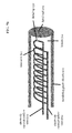
- FIG. 5 a depicts a side, cross-sectional view of the electrode of FIG. 2 configured as a wire coil, according to an embodiment of the invention.
- FIG. 5 b depicts a side, cross-sectional view of the electrode of FIG. 2 configured as a series of arcs, according to an embodiment of the invention.
- FIG. 5 c depicts a side, cross-sectional view of the electrode of FIG. 2 configured as series of circles, according to an embodiment of the invention.
- FIG. 6 a depicts a side, cross-sectional view of the apparatus demonstrating multiple interchangeable electrodes and the manner in which they connect to the stimulus generator.
- FIG. 6 b depicts a side, cross-sectional view (enlargement of FIG. 6 a ) showing separation of the two tips of a bipolar electrode caused by flexible bends near the distal end of the wires of a bipolar electrode, with the wires retracted within the insulating guide sheath, according to an embodiment of the invention.
- FIG. 6 c depicts a side, cross-sectional view of the bipolar electrode of FIG. 6 b , after incision of the tympanic membrane where the electrode enters the middle ear and the electrode wires are extended out of the insulating guide sheath, according to an embodiment of the invention.
- FIG. 7 a depicts a side, cross-sectional view of the distal tip of the apparatus having an insulating plug that is within the insulating guide sheath, according to an embodiment of the invention.
- FIG. 7 b depicts a side, cross-sectional view of the distal tip of the apparatus in FIG. 7 a with the insulating plug after incision of the tympanic membrane, where the electrode enters the middle ear and pushes the insulating plug out, according to an embodiment of the invention.
- FIG. 7 c depicts a side, cross-sectional view of the distal tip of the apparatus with an annulus where the electrode is within the insulating guide sheath, according to an embodiment of the invention.
- FIG. 7 d depicts a side, cross-sectional view of the distal tip of the apparatus of FIG. 7 c with the annulus after incision of the tympanic membrane, where the electrode enters the middle ear and perforates the annulus, according to an embodiment of the invention.
- FIG. 7 e depicts a side, cross-sectional view of the distal tip of the apparatus with the flower tip having the leaves closed and the electrode within the insulating guide sheath, according to an embodiment of the invention.
- FIG. 7 f depicts a side, cross-sectional view of the distal tip of the apparatus of FIG. 7 e with a flower tip having the leaves open after lancing the tympanic membrane, where the electrode enters the middle ear and forces open the closed tip, according to an embodiment of the invention.
- FIG. 8 depicts a side view of a speculum for use with the apparatus, according to an embodiment of the invention.
- FIG. 9 depicts a side, cross-sectional view of an ear piece of the apparatus with a stimulus generator placed on the external ear and an insulating guide sheath containing the electrode that are insertable into the ear canal, where the apparatus includes a wireless transmitter and receiver, according to an embodiment of the invention.
- FIG. 10 depicts a side, cross-sectional view of an ear piece of the apparatus with a stimulus generator placed on the external ear and an insulating guide sheath containing the electrode that are insertable into the ear canal, where the ear piece connects to the power source, according to an embodiment of the invention.
- FIG. 11 a depicts a side, cross-sectional view of an ear piece of the apparatus in which an electromagnetic coil forms the stimulus generator placed on the external ear, in which a guide piece positions the device over the ear canal, according to an embodiment of the invention.
- FIG. 11 b depicts an ear piece of the apparatus that positions an electromagnetic coil in a manner offset from the ear canal, according to an embodiment of the invention.
- FIG. 12 a depicts a side, cross-sectional view of an electromagnetic coil cylinder of the apparatus that is positioned in the ear canal by its form-fitting shape, according to an embodiment of the invention.
- FIG. 12 b depicts the electromagnetic coil cylinder of FIG. 12 a with a ferromagnetic bar placed through its lumen and into the middle ear space, according to an embodiment of the invention.
- FIG. 12 c depicts a side, cross-sectional view of the ear (enlargement of FIG. 12 b ) including stimulation by the ferromagnetic bar, according to an embodiment of the invention.
- FIG. 13 depicts a side, cross-sectional view of a stimulator device for chronic modulation of the facial nerve system implanted into the bones of the skull, according to an embodiment of the invention.
- FIG. 14 depicts a side, cross-sectional view of a stimulator device for chronic modulation of the facial nerve system placed into the middle ear, according to an embodiment of the invention.
- FIG. 15 is a flow diagram illustrating a method for stimulation of neural structures, according to an embodiment of the invention.
- FIG. 16 is a flow diagram illustrating another method for stimulation of neural structures, according to an embodiment of the invention.
- FIG. 17 is a flow diagram illustrating a continuation of the method for stimulation of neural structures of FIG. 16 , according to an embodiment of the invention.
- FIG. 18 is a flow diagram illustrating a chronic method for stimulation of neural structures, according to an embodiment of the invention.
- the purpose of stimulation of the facial nerve system by the apparatus is to modulate the cranial blood flow.
- Modulation of the cranial blood flow includes increasing, decreasing, redistributing, or otherwise changing blood flow to the cerebral, carotid, and/or extracerebral arteries, including but not limited to the arteries of the brain, brainstem, face, scalp, eyes, and neck.
- the apparatus stimulates the facial nerve system in order to increase blood flow to the brain of the subject for treatment of a stroke or to enhance delivery of a blood-borne pharmacologic agent to treat a condition of the subject.
- blood flow to the brain or other parts of the head is decreased.
- stroke refers to any type of stroke
- the phrase “stroke caused by atherosclerotic disease” refers specifically to stroke caused by atherosclerotic cerebral artery disease, which includes about 20% of all stroke.
- FIG. 1 depicts a side view of the apparatus 100 for treatment of conditions of the cerebral vasculature in which stimulation of part or all of the facial nerve system is accomplished through the ear, according to an embodiment of the invention.
- FIG. 1 illustrates various components of the ear, including the external ear 114 , the middle ear 116 , the inner ear 118 , the tympanic membrane 136 (ear drum), and the Eustachian tube 120 .
- the term “ear” refers to any portion of the ear, including the external, middle, and inner ear, unless otherwise specified.
- FIG. 1 also illustrates certain components of the nervous system including the facial nerve 124 and a branch 126 of the facial nerve passing through the middle ear 116 .
- facial nerve system includes, but is not limited to, the facial nerve, the geniculate ganglion, the tympanic plexus, the sphenopalatine nerves and ganglion, the petrosal nerves, the ethmoidal nerves, the palatine nerves, the vidian nerve, the communicating branches and connections of the aforementioned structures, and the communicating branches and connections between any of the aforementioned structures and the trigeminal, glossopharyngeal, or vagal nerves.
- These components of the facial nerve system are in the vicinity of, in proximity to, or are proximate to the ear 136 .
- the apparatus stimulates components of the facial nerve system that pass through, have a portion or branch within, or contribute to a structure within the middle ear 116 . Furthermore, in some embodiments, the apparatus stimulates components of the facial nerve system that have a portion or branch within the middle ear 116 or that are immediately outside the middle ear 116 .
- limited facial nerve system includes the nerves listed above, but not including the sphenopalatine nerves and ganglion, the petrosal nerves and communicating branches thereof, the ethmoidal nerves and communicating branches thereof, the palatine nerves including nasopalatine nerves, the vidian nerve and communicating branches thereof, and communicating branches between any of the aforementioned structures and the trigeminal nerve system.
- the apparatus 100 shown in FIG. 1 includes various components.
- the apparatus 100 includes an insulating guide sheath 104 having a proximal end 103 (end closest to the stimulus generator 106 and closest to the operator of the device) and a distal end 105 (end inside the ear, farthest from the operator of the device and stimulus generator).
- the insulating guide sheath 104 is moveable into and out of the ear (e.g., of a mammalian subject).
- the term “mammalian subject” or “subject” refers to any mammal, including humans.
- the insulating guide sheath 104 is rigid or substantially rigid (i.e., sufficiently rigid for translation into the ear but not inflexible) and is insertable into the ear via pressure or pushing of the proximal end 103 of the insulating guide sheath 104 to translate the distal tip 132 into the ear.
- the apparatus 100 also includes an electrode 102 that also has a proximal end 131 and a distal tip 132 .
- the term “electrode” includes a stimulation device that provides stimulation, such as stimulation or stimulus energy in the form of an electric current or in the form of an electromagnetic or magnetic field.
- the electrode 102 is housed within the insulating guide sheath 104 .
- the electrode 102 is a straight wire or plurality of wires. In some embodiments, the electrode 102 is a coiled wire or wire formed into a non-linear shape. In some embodiments, the electrode 102 and insulating guide sheath 104 together form a stimulator. In further embodiments, the distal tip 132 of the electrode 102 is detachable from the electrode 102 and is replaceable with a plurality of different distal tips that are attachable to the electrode 102 . Thus, the apparatus 100 can be reused with new/clean distal tips 132 if desired or if the type of stimulation (e.g., electrical, electromagnetic) delivered by the electrode 102 is to be changed.
- the type of stimulation e.g., electrical, electromagnetic
- the insulating guide sheath 104 is moveably disposed within the ear and the electrode 102 is moveably disposed within the insulating guide sheath 104 .
- the electrode 102 and insulating guide sheath 104 are advanced together into the ear.
- the insulating guide sheath 104 is advanced into the ear first, and the electrode 102 is advanced within the insulating guide sheath 104 and into the ear.
- the distal tip 132 of the electrode 102 can be advanced up to the distal end 105 of the insulating guide sheath 104 .
- the distal tip 132 is further advanced out of the distal end 105 of the insulating guide sheath 104 so that the distal tip 132 is exposed.
- FIG. 1 illustrates the primary position
- FIG. 3 illustrates the secondary position.
- the electrode 102 and the insulating guide sheath 104 are advanced into the ear canal 122 near to the tympanic membrane 136 , and the electrode 102 is disposed to remain inside the insulating guide sheath 104 (or the electrode tip can be translated out of the insulating guide sheath 104 and exposed, if desired).
- the electrode 102 remains external to the tympanic membrane 136 , and so remains within the ear canal 122 .
- the distal tip 132 of the electrode 102 is disposed for translation out of the distal end 105 of the insulating guide sheath 104 to be exposed (or it can be kept within the insulating guide sheath 104 if desired) and placed in proximity to a tympanic membrane 136 of the ear.
- the insulating guide sheath 104 and electrode 102 are passed into the middle ear 116 , and so are positioned internal to the tympanic membrane 136 .
- the tympanic membrane 136 is incised or punctured to insert the insulating guide sheath 104 and electrode 102 through the incised tympanic membrane 136 and into the middle ear 116 .
- the tympanic membrane 136 can be incised in various ways.
- the distal end 105 of the insulating guide sheath 104 is sharp, and this sharpened distal tip can be pushed through the tympanic membrane 136 to create an opening to reach the middle ear 116 .
- a separate instrument can be used to make an incision in the tympanic membrane 136 .
- both the insulating guide sheath 104 and electrode 102 are inserted into the middle ear 116 .
- only the electrode 102 is inserted into the middle ear 116 while the insulating guide sheath 104 remains in the ear canal 122 .
- the insulating guide sheath 104 is between 6 cm and 12 cm in length in order to allow access to the middle ear 116 through the ear canal 122 .
- the insulating guide sheath 104 can be fixed into position to prevent unintended movement.
- the insulating guide sheath 104 is fixed into position by inflation of an inflatable cuff 134 on the insulating guide sheath 104 in the ear canal 122 , though other stabilization mechanisms can also be used, including stabilization with an ear piece or clip fixed to the external ear 114 (not shown).
- the inflatable cuff 134 is attached to the outer wall of the insulating guide sheath 104 and the inflatable cuff 134 is configured to fit against a surface of the ear for holding the insulating guide sheath 104 in place within the ear.
- the inflatable cuff 134 can be used to fix the insulating guide sheath 104 into the primary position or the secondary position.
- a stimulus generator 106 can be in electrical communication with the electrode in 102 various ways.
- the stimulus generator 106 can be directly connected to the electrode 102 (e.g., connected via one or more wires or other connectors), or indirectly connected to or in communication with the electrode 102 .
- a power source 108 can be placed in electrical communication with the stimulus generator 106 for providing power to the stimulus generator 106 for supplying the stimulus energy to the electrode 102 .
- the power source 108 can also be directly or indirectly connected to the stimulus generator 106 .
- the power source 108 can connect to the stimulus generator 106 via one or more wires or other connectors, but the power source 108 can also indirectly connect to or be in communication with the stimulus generator 106 , such as via a wireless communication method.
- the power source 108 provides power to the stimulus generator 106
- the stimulus generator 106 provides stimulus energy to the electrode 102 that then provides stimulation to one or more aspects of the facial nerve system.
- the apparatus 100 can include an electrode advancer 110 to which the proximal end 131 of the electrode 102 is attached or associated.
- the electrode advancer 110 can include an advancement mechanism for advancing the electrode 102 within the insulating guide sheath 104 and/or for advancing the insulating guide sheath 104 into the ear.
- FIGS. 1-4 show the insulating guide sheath 104 and electrode 102 being inserted into the ear via the ear canal 122
- these components can be also configured for insertion into the middle ear 116 via a Eustachian tube 120 of the subject.
- Various disease processes in the ear canal or upon the tympanic membrane may impair access of medical devices through the ear canal.
- an apparatus capable of accessing the middle ear through the Eustachian tube 120 can be employed.
- the Eustachian tube 120 connects the middle ear 116 with the nasopharynx, allowing for pressure equilibration between the middle ear 116 and the external environment and for drainage from the middle ear 116 to enter the throat.
- the insulating guide sheath 104 and electrode 102 can be inserted into the Eustachian tube 120 without direct visualization through transnasal positioning, under direct visualization transnasally, or under direct visualization transorally. The insulating guide sheath 104 and electrode 102 can then be advanced along the Eustachian tube 120 and into the middle ear 116 .
- the insulating guide sheath 104 is between 20 cm and 30 cm in length in order to allow access to the middle ear 116 through the Eustachian tube 120 .
- the apparatus 100 can then be used as explained above, i.e., to apply stimulus energy to one or more components of the facial nerve system for stroke treatment, etc.
- the apparatus 100 further includes an injection port 112 connected to the insulating guide sheath 104 .
- the injection port 112 can be a tube or other structure attached to an opening in the wall of the insulating guide sheath 104 .
- the injection port 112 can include an opening on one end into which the user can insert a material, gel, or solution.
- the injection port 112 is used for injecting into the insulating guide sheath 104 a material, gel, or solution to facilitate treatment of the subject.
- the material, gel, or solution is contained within the insulating guide sheath 104 following injection, and in some embodiments, some or all of the material, gel, or solution is transferred through the insulating guide sheath 104 for release from the distal end 105 of the insulating guide sheath 104 .
- a variety of different materials, gels, or solutions can be placed into the lumen of the insulating guide sheath through the injection port 112 .
- an electrically-conductive gel or solution can be injected into an ear canal 122 or middle ear 116 of the subject to increase conductivity.
- an anesthetic or other pharmacological agent used to eliminate an unwanted response of tissue local to the electrode 102 can be injected into an ear canal 122 or middle ear 116 .
- the pharmacological agent can also be added to the conductive material, gel, or solution.
- the injection port 112 connects into a single lumen within the insulating guide sheath 104 . In other embodiments, the injection port 112 connects into one of a plurality of lumens within the insulating guide sheath 104 .
- the apparatus 100 further includes a stimulus controller 140 attached to the stimulus generator 106 for adjusting the stimulus energy applied to the electrode 102 .
- the stimulus controller 140 can include a user interface by which the operator of the apparatus can provide instructions to or otherwise interact with the apparatus 100 .
- the stimulus controller 140 can allow the operator to control the strength, frequency, and/or other parameters of the stimulus energy.
- the controller 140 can include particular controls (e.g., knobs, digital settings, etc.) for increasing or decreasing the strength of the current and controlling various other factors in the operation of the apparatus 100 .
- the apparatus 100 is connectable to a computer or other machinery, the operator may also be able to interact with and control the apparatus 100 via the interface of the computer, including tracking the subject's vital signs, responses to the stimulus energy over time, and so forth.
- the stimulus controller 140 can further be used to adjust the stimulus energy for various purposes.
- the stimulus energy can be adjusted based on one or more physiological or pathophysiological responses of the subject to the stimulus energy (e.g., taste sensation; audition; lacrimation; nasal drainage; nasal congestion; salivation; sound sensitivity; face, head, or hand movements; speech production or arrest; sensation of body movement; eye movements; cranial blood flow; direct or indirect activity of a nerve; and severity of neurological dysfunction of the subject).
- physiological or pathophysiological responses of the subject to the stimulus energy e.g., taste sensation; audition; lacrimation; nasal drainage; nasal congestion; salivation; sound sensitivity; face, head, or hand movements; speech production or arrest; sensation of body movement; eye movements; cranial blood flow; direct or indirect activity of a nerve; and severity of neurological dysfunction of the subject.
- the subject exhibits certain eye movements, the operator can observe this and respond to this by changing the stimulus energy or certain other parameters associated with the stimulus energy.
- the apparatus 100 itself can determine or interact with other instrumentation to detect certain physiological or pathophysiological responses of the subject to the stimulus energy, and the apparatus 100 can automatically adjust the stimulus energy in response.
- the stimulus energy can be adjusted to increase or otherwise control blood flow to the brain of the subject as either the direct treatment of a disease process or else to facilitate the delivery of blood-borne pharmacologic agents as the treatment of a disease process.
- the apparatus 100 also includes a stimulus generator 106 in electrical communication with the electrode 102 for supplying stimulus energy to the electrode 102 for stimulating one or more components of the facial nerve system.
- the stimulus energy is electrical current applied through the electrode 102 that creates an electromagnetic field 202 that is of sufficient strength to stimulate one or more components of the facial nerve system located in the vicinity of the ear.
- FIG. 2 illustrates the insulating guide sheath 104 and electrode 102 in the primary position, and further illustrates application of the stimulus energy, according to an embodiment of the invention.
- the stimulus energy is electrical current applied to the electrode 102 in order to create an electromagnetic field 202 that is of sufficient strength to stimulate one or more components of the facial nerve system located in, or in the vicinity of, the middle ear 116 .
- the electromagnetic field 202 is used to stimulate the facial nerve system with the electrode 102 being in the ear canal 122 , on the external side of the tympanic membrane 136 .
- the electromagnetic field 202 is defined by various combinations of the following parameters: a stimulation frequency ranging from 0.01 to 100 Hz; a field strength of 0.01 to 5.0 Tesla; a biphasic or oscillatory waveform.
- the electromagnetic field 202 is applied intermittently or periodically.
- stimulation with certain parameters reduces or redirects blood flow to the brain.
- failure of the electrode to achieve the desired result when used in the primary position is followed by advancement of the electrode 102 into the middle ear 116 to put the apparatus 100 into the secondary position.
- the tympanic membrane 136 is incised using the sharpened distal end 105 of the insulating guide sheath 104 or other mechanism for allowing the insulating guide sheath 104 and/or electrode 102 to enter the middle ear 116 .
- the insulating guide sheath 104 can be fixed into place in the ear canal 122 or advanced through the incision in the tympanic membrane 136 and then fixed into place, and the electrode 102 can be advanced past the distal end 105 of the insulating guide sheath 104 into the middle ear 116 . Electrical current can then be applied through the exposed tip of the electrode 102 in order to stimulate one or more components of the facial nerve system. This is referred to as the secondary position. In the secondary position, one or more components of the facial nerve present within the middle ear 116 can be subjected to stimulation by direct exposure to electrical current.
- the electrode comprises a cathode and an anode.
- the closest distance between the cathode and the anode is greater than the closest distance between any portion of the cathode and any portion of a tympanic plexus, facial nerve, or other neural structure of the middle ear.
- the electrode is monopolar and a ground wire is applied to an external ear or other part of the head.
- FIG. 3 illustrates the apparatus 100 in the secondary position, according to an embodiment of the invention.
- the insulating guide sheath 104 has been fixed into place by the inflatable cuff 134 in the ear canal 122 .
- the insulating guide sheath 104 has been used to incise the tympanic membrane 136 .
- the incision 302 e.g., puncture hole
- the electrode 102 has further been advanced within the insulating guide sheath 104 so that the distal tip 132 of the electrode 102 is exposed.
- the distal tip 132 of the electrode 102 is positioned near a branch 126 of the facial nerve 124 that is passing through middle ear 116 .
- FIG. 4 illustrates the apparatus 100 in the secondary position with the stimulus energy being applied to the electrode 102 .
- FIG. 4 illustrates direct electrical stimulation 402 of a facial nerve branch 126 in the middle ear 116 .
- the electrode is retained within the insulating guide sheath 104 and application of the electrical current to the electrode 102 creates an electromagnetic field 202 that penetrates various tissues in order to stimulate components of the facial nerve system.
- the electrical stimulation 402 is defined by various combinations of the following parameters: a stimulation frequency ranging from 0.1 to 100 Hz; a current of 0.1 to 5.0 mA; a biphasic waveform with or without a delay between the phases.
- the electrical stimulation 402 is provided intermittently or periodically. In some embodiments, stimulation with certain parameters decreases or shunts off blood flow to the brain.
- FIGS. 5 a - c illustrate the distal tip 132 of the apparatus 100 used in the primary position, and further illustrate examples of various configurations of the distal tip 132 of the electrode 102 suitable for generating an electromagnetic field 202 .
- FIG. 5 a illustrates the distal tip 132 of the electrode 102 configured as a wire coil 504 with repeating loops that connects at one end to the electrode current inflow wire 502 and at the other end to the electrode current outflow wire 506 , according to an embodiment of the invention.
- the electrode current inflow wire 502 and electrode current outflow wire 506 are separated by an insulating septum 508 or other means of insulation within the lumen 512 of the insulating guide sheath 104 .
- FIG. 5 a illustrates the distal tip 132 of the apparatus 100 used in the primary position, and further illustrate examples of various configurations of the distal tip 132 of the electrode 102 suitable for generating an electromagnetic field 202 .
- FIG. 5 a illustrates the distal tip 132
- the wire coil 504 is positioned near the distal end 105 of the insulating guide sheath 104 with its axis largely parallel to the direction of the electrode wires. In other embodiments, the wire coil 504 is positioned within the lumen 512 of the insulating guide sheath 104 with its axis largely perpendicular to, or significantly angled away from, the direction of the electrode wires (not shown). In some embodiments, the wire coil 504 is tapered as is a cone. In some embodiments, the wire coil 504 has an outer diameter of less than 6 mm, an inner diameter of at least 2 mm, and a length of 10-30 mm. In some embodiments, the wire coil is coiled into 5-25 layers with 50-250 turns per layer.
- FIG. 5 b illustrates the distal tip 132 of an electrode 102 configured as one or more wire arcs 514 , according to an embodiment of the invention.
- a series of arcs are placed at the distal tip 132 of the electrode 102 between the electrode current inflow wire 502 and the electrode current outflow wire 506 , so as to form electrical connections between the electrode current inflow wire 502 and the electrode current outflow wire 506 .
- the arcs are inclined from the plane formed by the electrode current inflow wire 502 and the electrode current outflow wire 506 within the lumen 512 of the insulating guide sheath 104 .
- the distance between the electrode current inflow wire 502 and the electrode current outflow wire 506 is minimal, thereby pulling the wire arcs 514 into substantially noose-like shapes (not shown). In some embodiments, 4-50 wire arcs 514 are employed.
- FIG. 5 c illustrates the distal tip 132 of an electrode 102 configured as one or more wire circles 516 , according to an embodiment of the invention.
- the wire circles 516 are placed between the electrode current inflow wire 502 and the electrode current outflow wire 506 so that the electrode current inflow wire 502 and the electrode current outflow wire 506 connect to the wire circles 516 at a single point.
- the wire circles 516 are placed between the electrode current inflow wire 502 and the electrode current outflow wire 506 so that their planes are not perpendicular to the direction of the electrode current inflow wire 502 or the electrode current outflow wire 506 .
- the wire circles 516 are distorted so that their shape is substantially oval.
- the wire circles 516 are distorted so that all the points along the wire do not lie within a single plane (not shown).
- the wire and insulating guide sheath 104 can be constructed in various ways.
- the wire comprising the shapes illustrated in FIGS. 5 a - c is between 0.06-0.60 mm in diameter.
- the insulating guide sheath 104 is composed of poly(4,4′-oxydiphenylene-pyromellitimide) (KAPTON®), polyimide, or polytetrafluoroethylene (PTFE or TEFLON®).
- the insulating guide sheath 104 is prepared with a conformal coating.
- FIGS. 6-14 Everything described above including the various embodiments of the distal tip of the electrode described in FIGS. 5 a - c can apply to the remaining designs, such as FIGS. 6-14 .
- the description of the sizes, shapes, designs, and materials used in the construction of the components of FIGS. 5 a - c can apply to the apparatus designs of FIGS. 6-14 .
- these details are not repeated again below for each of FIGS. 6-14 .
- FIG. 6 a illustrates an apparatus 600 that allows for exchange of electrodes for use in the primary and secondary positions, according to an embodiment of the invention.
- a junction is formed by the union of a distal coupler 608 and proximal coupler 606 , in which the distal coupler 608 is in electrical communication with the electrode 102 at the proximal end 103 of the insulating guide sheath 104 , and in which the proximal coupler 606 is in communication with the stimulus generator 106 .
- Connection of the proximal coupler 606 and the distal coupler 608 places the electrode in electrical continuity with the stimulus generator 106 allowing stimuli to be delivered through the electrode that then generates an electromagnetic field 202 .
- the electromagnetic field stimulator described above is removed by disconnection of the distal coupler 608 from the proximal coupler 606 specific for that stimulator type. Then, a stimulator type appropriate for the secondary position is attached, e.g., through a distinct junction.
- an electrode capable of delivering direct electrical stimulation through its uninsulated distal tip 132 is attached by means of a distal coupler 604 at the proximal end 131 of the electrode to a proximal coupler 602 on the stimulus generator 106 , wherein the distal coupler 604 and the proximal coupler 602 are specific for this type of electrode and are not typically used with other electrode types (e.g., those that generate electromagnetic fields). Connection of the proximal coupler 602 and the distal coupler 604 places the electrode in electrical continuity with the stimulus generator 106 , allowing stimuli to be delivered through the electrode and released from the distal tip 132 as direct electrical current or voltage.
- attachment of one electrode type by means of connection of the proximal coupler 602 , 606 to the distal coupler 604 , 608 prohibits the simultaneous attachment of another electrode type to the apparatus.
- attachment of an electrode type by means of a proximal coupler 602 , 606 and a distal coupler 604 , 608 determines, adjusts, or limits the power delivered by the power source 108 .
- a bipolar electrode is used to deliver stimulation in the secondary position of the device, as shown in FIG. 6 a .
- an electrode rotator 610 is positioned at or near the proximal end 131 of the electrode for use in the secondary position.
- the electrode rotator 610 is used to rotate one pole of the bipolar electrode around the second pole, or else to rotate both poles around a common axis, or to otherwise adjust the positioning of the electrode.
- rotation of one or more of the electrode poles is achieved by rotating the insulating guide sheath 104 that houses the poles of the bipolar electrode.
- An electrode advancer 110 can also be attached at or near the proximal end of the bipolar electrode such that one or both poles of the bipolar electrode can be advanced from, or retracted into, the insulating guide sheath 104 .
- a bipolar electrode is formed by a cathodic wire 506 and an anodic wire 502 that are housed within separate lumens within the insulating guide sheath 104 .
- separate lumens are formed by an insulating septum 508 or other such division.
- flexible bends 652 are placed in the electrode wire near the distal ends of the cathodic wire 626 and anodic wire 622 . As shown in FIG. 6 c , when the electrode wires are advanced out of the distal end 105 , the flexible bends 652 spread the tips of the electrode wires apart by a predetermined distance.
- separate lumens within the insulating guide sheath 104 open at different positions along the length of the insulating guide sheath 104 so that a fixed distance exists between the cathodic wire 626 and anodic wire 622 once the wires are advanced out of the insulating guide sheath 104 (not shown).
- the wire or wires of the electrode for use in the secondary position to deliver stimulation in the middle ear 116 is/are formed or constructed in various ways.
- the wire or wires is/are formed from stainless steel, platinum, silver alloy, gold alloy, or nitinol.
- the wire or wires of the electrode may be square or in a strip shape.
- the wire or wires of the electrode may be capped at their distal ends so as to be non-traumatic once extended from the insulating guide sheath 104 .
- FIGS. 7 a and 7 b illustrate the distal end 105 of the insulating guide sheath 104 , according to an embodiment of the invention.
- FIG. 7 a illustrates the electrode 102 within the hollow lumen 512 of the insulating guide sheath 104 for use in the primary position.
- the distal end 105 of the insulating guide sheath 104 includes a cutting edge 702 that is used to incise or create an opening in the tympanic membrane 136 through which the insulating guide sheath 104 and electrode 102 can be passed.
- FIG. 7 a further shows an insulating plug 706 attached to the distal tip 132 of the electrode 102 .
- the insulating plug 706 protects and insulates the distal tip 132 of the electrode 102 .
- FIG. 7 a shows the electrode retracted within the hollow lumen 512 of the insulating guide sheath 104 .
- FIG. 7 b shows the distal tip 132 of the electrode 102 extended from the hollow lumen 512 of the insulating guide sheath 104 .
- the electrode 102 pushes the insulating plug 706 out of the insulating guide sheath 104 and enters the middle ear 116 , achieving the secondary position.
- FIGS. 7 c and 7 d illustrate the distal end 105 of the insulating guide sheath 104 , according to an embodiment of the invention.
- FIG. 7 c illustrates the electrode 102 within the hollow lumen 512 of the insulating guide sheath 104 for use in the primary position.
- FIGS. 7 c and 7 d illustrate an embodiment in which the distal end 105 of the insulating guide sheath 104 includes a cutting edge 702 that is used to incise the tympanic membrane 136 through which the insulating guide sheath 104 and electrode 102 can then be passed.
- FIG. 7 c further shows an intact annulus 708 and FIG.
- FIG. 7 d shows a perforated annulus 710 .
- FIG. 7 c shows the electrode retracted within the hollow lumen 512 of the insulating guide sheath 104 .
- FIG. 7 d shows the distal tip 132 of the electrode 102 extended from the hollow lumen 512 of the insulating guide sheath 104 through the annulus, causing perforation of the annulus.
- the electrode 102 perforates the annulus to insert the distal tip 132 of the electrode 102 into the middle ear 116 , achieving the secondary position.
- FIGS. 7 e and 7 f illustrate the distal end 105 of the insulating guide sheath 104 , according to an embodiment of the invention.
- FIG. 7 e illustrates the electrode 102 within the hollow lumen 512 of the insulating guide sheath 104 for use in the primary position.
- FIGS. 7 e and 7 f illustrate an embodiment in which the insulating guide sheath 104 includes a pointed tip 712 that is used to incise the tympanic membrane 136 through which the insulating guide sheath 104 and electrode 102 can be passed.
- FIG. 7 e illustrates the electrode 102 within the hollow lumen 512 of the insulating guide sheath 104 for use in the primary position.
- FIGS. 7 e and 7 f illustrate an embodiment in which the insulating guide sheath 104 includes a pointed tip 712 that is used to incise the tympanic membrane 136 through which the insulating guide sheath 104 and electrode 102
- FIG. 7 e shows the electrode 102 retracted within the hollow lumen 512 of the insulating guide sheath 104 and the closed end 714 of the insulating guide sheath 104 .
- FIG. 7 f shows the open end 716 of the insulating guide sheath 104 .
- the distal end 105 of the insulating guide sheath 104 in this embodiment includes three leaves (though more or fewer leaves can be included) that are moved apart to open the closed end 714 . Once open, the distal tip 132 of the electrode 102 is extended from the hollow lumen 512 of the insulating guide sheath 104 . Thus, after lancing the tympanic membrane 136 , the electrode 102 forces open the closed end 714 of the insulating guide sheath 104 and enters the middle ear 116 , achieving the secondary position.
- FIG. 8 illustrates a speculum 800 for use with the apparatus 100 , according to an embodiment of the invention.
- Placement of the insulating guide sheath 104 and electrode 102 in the ear canal 122 or in the middle ear 116 may require a specialized otoscope speculum 800 that will allow for direct visualization of anatomical structures.
- the ear speculum 800 can be composed of a hollow, largely conical structure with openings at its proximal end 802 and distal end 804 .
- the speculum 800 can also be modified with a groove 806 or other peripheral channel along its lateral length, where the groove 806 or other peripheral channel is of sufficient size to accommodate the guide sheath 104 .
- the groove 806 allows for lateral passage of the insulating guide sheath 104 and for manipulation of the insulating guide sheath 104 and electrode 102 .
- the groove 806 can be on the outside of the speculum 800 or can be inside the speculum 800 .
- the groove 806 can be open along its length so that the speculum 800 can be separated from the insulating guide sheath 104 once the speculum 800 is removed from the ear (e.g., after successful positioning of the insulating guide sheath 104 ).
- the groove 806 can also be closed along its length to hold the insulating guide sheath 104 in place during placement of the insulating guide sheath 104 in the ear. Where the groove 806 is closed, it can include a latch or other mechanism for opening the groove 806 to release the insulating guide sheath 104 .
- the distal end 804 of the speculum 800 is placed into the ear facing into the tympanic membrane 136 for direct visualization inside the ear canal 122 .
- the proximal end 802 of the speculum 800 faces toward an operator and may be connected to an otoscope which will allow the visualization.
- Light 810 can be shone through the opening in the speculum 800 and into the ear canal 122 to view the inside of the ear.
- the opening of the proximal end 802 of the speculum 800 is significantly larger than the opening of the distal end 804 of the speculum 800 , and the proximal end 802 can be attached to an ordinary otoscope from which light is projected through the hollow lumen of the speculum 800 .
- the distal end 804 of the speculum 800 can be inserted into the ear canal 122 of the subject, allowing direct visualization of the ear canal 122 and tympanic membrane 136 .
- the insulating guide sheath 104 and electrode 102 can then be advanced down the length of the groove 806 in the speculum 800 and manipulated into proper position.
- FIG. 9 illustrates a side view of apparatus 900 with the stimulus generator 106 resting against the external ear 114 , according to an embodiment of the invention.
- the stimulus generator 106 is an outer covering, plug, or other design that sits outside the ear canal 122 .
- the stimulus generator 106 is shaped as a ring or a hook that sits upon the pinna, concha, scapha, tragus, or antitragus of the external ear (not shown).
- the stimulus generator 106 is comprised of a wireless transmitter 908 and a wireless receiver 906 .
- the electrode 102 and the insulating guide sheath 104 are connected to the wireless receiver 906 , and the wireless receiver 906 sits against the external ear 114 in a manner that places the electrode 102 and insulating guide sheath 104 inside the ear canal 122 , bringing the distal tip 132 of the electrode 102 into proximity to the tympanic membrane 136 .
- Proximity to the tympanic membrane 136 is defined in relation to either the internal face of the tympanic membrane (observed from the position in the middle ear 116 ) or the external face of the tympanic membrane (observed from the position of the ear canal 122 ).
- the distal tip 132 of the electrode 102 is placed through an incision 302 in the tympanic membrane 136 within the middle ear 132 , achieving the secondary position.
- the distal tip 132 of the electrode 102 is placed near the external face of the tympanic membrane 136 within the ear canal 122 , achieving the primary position (not shown).
- the wireless receiver 906 is held in place on the external ear 114 by an ear piece 902 that rests against the head, in this embodiment behind the external ear 114 .
- a variety of other ear piece designs can be used for holding the wireless receiver 906 in place as well.
- the ear piece 902 is designed in FIG.
- the apparatus 900 further includes a wireless transmitter 908 that can be separate and unattached from the body of the subject, or that can be attached to the body somewhere on the body or in clothing on the body (e.g., in a pocket, attached to a belt, worn around the neck, etc.).
- the wireless transmitter 908 is directly or indirectly in communication with a power source 108 that provides power to the wireless transmitter 908 .
- one or more wires electrically couple the power source 108 to the wireless transmitter 908 .
- the wireless transmitter 908 can communicate with the wireless receiver 906 on the distal ear piece 904 to generate stimulus energy for the electrode 102 .
- the wireless receiver 906 and the wireless transmitter 908 can be electromagnetically or inductively coupled.
- the apparatus 900 of FIG. 9 can be a chronic treatment device or can be an acute treatment device.
- the apparatus 900 can be placed on the subject's ear, and can deliver stimulus energy as desired by a physician or other operator.
- the stimulus generator 106 can be attached to a stimulus controller 140 that allows a physician or other operator to control when the energy is delivered, the intensity of the energy, etc.
- the apparatus 900 can be worn as a chronic treatment device that is worn regularly by the subject. It can be worn all the time, at certain times of day, or whenever prescribed.
- the apparatus 900 can thus chronically stimulate and modulate one or more components of the facial nerve system in the vicinity of the ear.
- one or more components of the chronic treatment apparatus are shaped to fit into an ear canal of the subject or against the external ear (e.g., as shown in FIG. 9 or another design to be worn externally by the subject).
- the components are on an external side of the tympanic membrane for chronically stimulating and modulating one or more components of the facial nerve system in the vicinity of the ear.
- FIG. 10 illustrates a side view of apparatus 1000 with the stimulus generator 106 resting against the external ear 114 , according to an embodiment of the invention.
- the design is similar to that of FIG. 9 , but in this case the power source 108 directly connects to the distal ear piece 904 .
- the stimulus generator 106 is represented as a single object that received power from the power source 108 through the ear piece 902 .
- the distal tip 132 of the electrode 102 can be placed in proximity to the tympanic membrane 136 , achieving either the primary or secondary position as needed.
- FIG. 11 a illustrates a side view of apparatus 1100 with an electromagnetic coil 1102 resting against the external ear 114 , according to an embodiment of the invention.
- the coil 1102 has a central opening 1106 through which light 810 and sound can be transmitted.
- the electromagnetic coil 1102 is worn against the external ear using an ear piece.
- This ear piece can be similar to ear piece 902 (including connecting directly to the stimulus generator 106 which connects directly to the power source 108 ), as is shown in FIG. 10 , or can be designed in a different manner as desired.
- the apparatus can include the wireless transmitter/receiver design of FIG. 9 , in which the ear piece 902 does not connect directly to the power source 108 , but is worn as apparatus 900 is worn.
- the electromagnetic coil 1102 acts as the stimulus generator in this embodiment, and provides the stimulus energy by producing an electromagnetic field 202 through which one or more components of the facial nerve system are stimulated.
- the electromagnetic coil 1102 is shaped largely as a circle or ring, as shown in FIG. 11 a . In other embodiments, the electromagnetic coil 1102 is shaped as a figure-8, a cloverleaf, or other configuration. A detachable connection between the distal ear piece 902 and the stimulus generator 106 allows for attachment of various configurations of the electromagnetic coil 1102 . In some embodiments, the electromagnetic coil 1102 is between 2 cm and 8 cm in diameter.
- the guide piece 1108 attached to the electromagnetic coil 1102 , where the guide piece is inserted into the ear canal 122 when the electromagnetic coil is placed against the external ear 114 .
- the insertable guide piece 1108 can be a sound-dampening ear plug or a speculum for visualization of the tympanic membrane 136 .
- the guide piece 1108 is positioned on the electromagnetic coil 1102 in a manner that orients the generated electromagnetic field 202 in a certain direction.
- the guide piece 1108 is composed of ferromagnetic material that distorts or modifies the electric or magnetic field generated by the electromagnetic coil 1102 in a desirable manner.
- the guide piece 1108 includes one or more fiducial markers that indicate the expected direction or position of the electromagnetic field 202 on an imaging study.
- FIG. 11 b some embodiments of the apparatus 1150 involve offsetting the electromagnetic coil 1152 from a position immediately over the ear canal in a manner determined by its attachment to the ear piece 902 .
- FIG. 11 b shows an electromagnetic coil 1152 shaped largely like an elongated pentagon in which attachment to the ear piece 902 at a position behind the external ear 114 places the electromagnetic coil 1152 over or near to the mastoid region 1170 , above the temporal bone.
- the electromagnetic coil 1152 in this embodiment acts as the stimulus generator, and provides the stimulus energy by producing an electromagnetic field through which one or more components of the facial nerve system are stimulated.
- the electromagnetic coil 1152 is connected through the ear piece 902 to the stimulus generator 106 which connects directly to the power source 108 .
- FIG. 12 a illustrates a side view of apparatus 1200 with an electromagnetic coil 1202 resting partially or completely inside the ear canal 122 , according to an embodiment of the invention.
- the coil 1202 has a central opening 1106 through which light 810 and sound can be transmitted.
- This design is similar to FIG. 11 a except that the coil 1202 forms a column that rests in, is wedged in, or is surgically attached to or implanted into the ear canal 122 .
- the electromagnetic coil 1202 can further connect directly to the stimulus generator 106 which connects directly to the power source 108 .
- the apparatus 1200 can include the wireless transmitter/receiver design of FIG. 9 .
- the electromagnetic coil 1202 of FIG. 12 a acts as the stimulus generator and electrode in this embodiment, and provides the stimulus energy by producing an electromagnetic field 202 that stimulates one or more components of the facial nerve system.
- FIG. 12 b illustrates a side view of apparatus 1250 in which an electromagnetic coil 1202 is placed in the ear canal 122 without use of a supporting ear piece, inflatable cuff, or other similar positioning assistance, but rather is kept in position by its form-fitting shape.
- a ferromagnetic bar 1252 is placed within the central opening 1106 of the electromagnetic coil 1202 such that magnetic energy is conducted through the ferromagnetic bar 1252 to its distal end 1254 . As illustrated in FIG.
- the distal end 1254 of the ferromagnetic bar 1252 near the facial nerve 124 as the nerve courses behind the middle ear 116 space allows for generation of a magnetic field 1256 surrounding the distal end 1254 that then stimulates the facial nerve 124 .
- This placement involves advancing the distal end 1254 of the ferromagnetic bar 1252 into the middle ear 116 through an incision 302 in the tympanic membrane 136 .
- the ferromagnetic bar 1252 has a 180-degree bend within the electromagnetic coil 1202 so that the proximal and distal ends of the ferromagnetic bar 1252 are brought into proximity in an elongated “horseshoe” structure (not shown).
- the ferromagnetic bar is composed of Permalloy or Mu-metal.
- the magnetic field carried by the ferromagnetic bar is focused or amplified by placement of ferromagnetic material in the facial nerve canal, fallopian aqueduct, or middle ear space.
- Atherosclerotic disease of the cerebral arteries narrows cerebral arteries, which may chronically impair blood flow to parts of the brain, thereby causing among other symptoms recurring near-strokes/transient ischemic attacks as blood flow becomes intermittently compromised.
- chronic stimulation of the facial nerve system provided by a chronic treatment device can be used to maintain dilation of the arteries, thereby preventing stroke caused by atherosclerotic disease.
- FIG. 13 illustrates a side view of apparatus 1300 with the electrode 102 chronically positioned within the bone of the skull and/or soft tissues of the head for stimulation of one or more components of the facial nerve system, according to an embodiment of the invention.
- the electrode 102 is positioned in proximity to a branch 126 of the facial nerve 124 that passes through the middle ear space 116 . Stimulation can then be achieved by application of electrical current from a stimulus generator 106 .
- the stimulus generator 106 and power source 108 are implanted within the body, thereby allowing direct connection between the electrode 102 and the stimulus generator 106 .
- a power source 108 that is connected directly to the stimulus generator 106 by one or more wires or other connectors.
- a stimulus controller 140 controls one or more parameters of the stimulus energy applied to the electrode 102 by the stimulus generator 906 using a wireless transmitter 908 external to the body that transmits information to a wireless receiver 906 connected to the stimulus generator 106 where the wireless receiver 906 is implanted within the body.
- FIG. 14 illustrates a side view of apparatus 1400 with the electrode 102 positioned within the middle ear 116 by means of the Eustachian tube 120 for stimulation of one or more components of the facial nerve system, according to an embodiment of the invention.
- the electrode 102 is in direct connection with a stimulus generator 106 placed within the middle ear 116 or the Eustachian tube 120 .
- Stimulus energy from a power source 108 with parameters determined by a stimulus controller 140 can be provided to the stimulus generator 106 either by direct connection between the stimulus controller 140 and the stimulus generator 106 through the Eustachian tube (not shown) or wirelessly by transmission of the stimulus energy from a wireless transmitter 908 placed external to the body to a wireless receiver 906 that is in direct connection with the stimulus generator 906 .
- a wireless transmitter 908 is an aural appliance (not shown) configured to fit against the external ear 114 . Circuitry in the wireless transmitter 908 can drive the wireless transmitter 908 to transmit stimulus energy to the wireless receiver 906 . Similarly, circuitry in the wireless receiver 906 can receive the stimulus energy and transmit the energy to the stimulus generator 106 .
- the apparatus 1400 positioned in the middle ear 116 in this manner and supplied with stimulus energy by wireless transmission can be used for acute or chronic treatment of a disorder of abnormal blood flow within the head.
- Electrical stimulation 402 of a branch 126 of the facial nerve can be performed, as in this example, or other means of stimulation can be employed.
- direct connection of the stimulus generator 106 and the stimulus controller 140 can be maintained by one or more wires running through the Eustachian tube 120 and exiting the head via nasal or oral passages.
- FIG. 15 there is shown a flow diagram providing a method for neural structure modulation, according to an embodiment of the invention. It should be understood that these steps are illustrative only. Different methods of the invention may perform the illustrated steps in different orders, omit certain steps, and/or perform additional steps not shown in FIG. 15 (the same is true for the other Figures).
- the method can start and end at various points in the process, and often the method is a continuous process with multiple steps occurring simultaneously, so the Figures provide only an example of one ordering of method steps.
- the method can be performed using any of the apparatuses described herein or another apparatus capable of performing the steps provided below.
- the method includes a step of providing stimulation 1502 in the ear canal (primary position).
- the stimulation can include providing stimulus energy to an electrode positioned in the ear canal, in the primary position for the apparatus. This may result in sufficiently improving 1504 blood flow to the brain, thus rendering the treatment of the stroke a success.
- stimulation in the primary position may not be successful for one of two reasons. First, stimulation 1508 in the primary position may not sufficiently improve blood flow to the brain, thus rendering the treatment of the stroke a failure. Second, even if blood flow to the brain is sufficiently improved by stimulation in the primary position, side effects associated with stimulation in the primary position may prevent the use of stimulation in the primary position 1506 .
- the method can further include a step of advancing an electrode into the middle ear by puncturing the tympanic membrane and inserting the electrode through the punctured tympanic membrane.
- the method can also include providing stimulation 1510 from this position in the middle ear, which is the secondary position for the apparatus.
- the electrode In this secondary position, the electrode is closer to some components of the facial nerve system for providing stimulation to improve blood flow, and certain components of the facial nerve system can be directly stimulated with electrical current.
- the stimulation 1510 provided from the secondary position may result in sufficiently improving 1504 blood flow, thus rendering the treatment of the stroke a success.
- the method includes first trying to stimulate the facial nerve system from the primary position (in the ear canal), and if this position does not provide the desired results, the method includes then trying to stimulate the facial nerve system from the secondary position (in the middle ear).
- the user does not have to perform the steps in this order, or may perform only one of the steps. For example, only the secondary position may be used if this is preferred.
- the method includes moving 1602 the insulating guide sheath within a Eustachian tube of the ear to an internal side of the tympanic membrane. This method then continues to a step that includes moving 1613 the electrode within the insulating guide sheath (note that the moving 1602 of the insulating guide sheath and moving 1613 of the electrode can occur simultaneously).
- the method follows a different course in the flowchart. If a speculum is to be used, the speculum is inserted 1606 into the ear canal, and the insulating guide sheath is inserted 1608 into the speculum.
- the insulating guide sheath can be inserted 1608 through a groove or peripheral channel along the lateral length of a specialized otoscope speculum and then into the ear canal of the subject under direct visualization of anatomical structures within the ear.
- the insulating guide sheath is moved 1610 into the ear canal without a speculum.
- the moving 1610 of the insulating guide sheath into the ear can include moving the insulating guide sheath into the ear canal and into proximity of the tympanic membrane.
- the user can opt to proceed with stimulation from the ear canal (primary position), or can opt to advance the device into the middle ear to perform the stimulation in the middle ear (secondary position). If the stimulation is to occur in the middle ear, the moving 1610 of the insulating guide sheath into the ear can lead to steps of puncturing 1604 the tympanic membrane with the insulating guide sheath (e.g., a sharpened distal tip of the insulating guide sheath) or other surgical procedure and moving 1605 the insulating guide sheath into the middle ear. In some embodiments, the user might opt to first provide stimulation from the ear canal, and if the appropriate response does not occur, the user can then opt to move the device into the middle ear for providing stimulation in the middle ear.
- the insulating guide sheath e.g., a sharpened distal tip of the insulating guide sheath
- the method further includes moving 1612 the distal tip of the electrode within the insulating guide sheath to the end of the insulating guide sheath (for stimulation in the primary position) or moving 1613 the distal tip of the electrode out of the distal end of the insulating guide sheath (for stimulation in the secondary position). This can also occur simultaneously with the any of the steps described above or it may precede any of the steps in certain methods.
- the distal tip of the electrode can remain inside the insulating guide sheath in a position near the external side of the tympanic membrane and in the secondary position, the distal tip can be exposed near an internal side of the tympanic membrane.
- the method also includes stabilizing 1615 the insulating guide sheath to hold the insulating guide sheath in place within the ear while the distal tip of the insulating guide sheath is located in the middle ear, or stabilizing 1616 the insulating guide sheath to hold the insulating guide sheath in place within the ear while the distal tip of the insulating guide sheath is located in the ear canal.
- Stabilizing 1615 , 1616 can include inflating an inflatable cuff associated with the outer wall of the insulating guide sheath to fit the insulating guide sheath against a surface of the ear or to hold the insulating guide sheath in place within the ear canal. Stabilizing 1615 , 1616 can further include stabilization with an ear piece fixed to the external ear.
- the method includes injecting 1702 such material, gel, or solution through an injection port out the distal tip of the insulating guide sheath to facilitate treatment of the subject. This can also occur earlier or later in the process, or at multiple times in the process with the same or different materials, gels, or solutions, as desired.
- the material, gel, or solution can be released from the distal end of the insulating guide sheath into an ear canal, middle ear, or Eustachian tube.
- the method also includes providing 1704 power via a power source for supplying the stimulus energy to the electrode (the power may also be provided 1704 automatically, as the device may be constantly connected to or in communication with the power source).
- the power can be provided 1704 via wires connecting the power source to the device, or wirelessly via a wireless transmitter/receiver.
- the method includes supplying 1706 stimulus energy to the electrode to stimulate one or more components of the facial nerve system in the vicinity of the ear (e.g., a facial nerve, a tympanic plexus, a geniculate ganglion, a tympanic plexus, a sphenopalatine nerve or ganglion, a petrosal nerve, etc.).
- supplying 1706 stimulus energy to the electrode modulates blood flow to the brain of the subject or enhances delivery of a blood-borne pharmacologic agent to treat stroke or another condition of the subject.
- the stimulus energy can be supplied via a wire connecting a stimulus generator to the electrode or wirelessly via a stimulus generator that is not in direct contact with the electrode.
- supplying 1706 stimulus energy can create an electromagnetic, electric, or magnetic field to stimulate the facial nerve system from the external side of the tympanic membrane.
- an electrical current can be directly supplied to components of the facial nerve system within the middle ear and may also be provided to certain components of the facial nerve system indirectly (e.g., via an electromagnetic field).
- supplying 1706 stimulus energy drives electrical current between a cathodic site and an anodal site of a bipolar electrode.
- supplying 1706 stimulus energy drives electrical current from a monopolar electrode to a ground wire applied to the pinna of the ipsilateral or contralateral ear, or to another part of the head.
- the method can include adjusting 1708 the stimulus energy. For example, the adjustments can be made based on physiological or pathophysiological responses of the subject to the stimulus energy.
- the method can continue with supplying 1706 and adjusting 1708 as needed until the method is done.
- the insulating guide sheath and/or electrode can be removed 1718 from the ear. If the device has a detachable electrode tip, the method can include detaching 1720 the tip and attaching 1722 a new tip.
- the method can continue to completion with steps 1602 , 1604 , 1605 , 1606 , 1608 , 1610 , 1613 , 1615 , 1702 , 1704 , 1706 , 1708 , 1718 , 1720 , and/or 1722 , described above.
- the device can then be moved into the secondary position in the middle ear if stimulation in the middle ear is judged appropriate.
- the method includes surgically, interventionally, or endoscopically implanting 1802 the chronic treatment device (e.g., an electrode with or without an insulating sheath) within or in proximity to the ear of the subject.
- the chronic treatment device e.g., an electrode with or without an insulating sheath
- This may include placement of the chronic treatment device in the middle ear space, in the Eustachian tube, into a bone of the skull, or into a soft tissue or potential space of the head.
- the method includes placing 1804 the chronic treatment device into the ear canal, on the external ear, or on the surface of the head (e.g., the mastoid region behind the external ear) of the subject. Certain positions may only allow for stimulation of one or more components of the limited facial nerve system.
- the device can be implanted into the facial nerve canal, the Eustachian tube, the internal auditory meatus, the Fallopian aqueduct, the mastoid antrum, the temporal bone, the cartilage of the ear, or the epitympanic recess of the subject.
- the method also includes supplying 1806 stimulation (e.g., via a stimulus generator that can be in wireless communication with the electrode) to the electrode over a period of time to chronically stimulate one or more components of the facial nerve system in the vicinity of the ear.
- the supplying 1806 of stimulation step includes supplying stimulation automatically over a period of time to maintain relaxation of one or more cerebral or carotid arteries associated with the facial nerve system for treatment or prevention of a stroke, particularly stroke caused by atherosclerotic disease.
- the method can further include providing 1808 power via a power source for supplying the stimulus energy to the electrode.
- the method can also include monitoring 1810 one or more physiological or pathophysiological responses of the subject over a period of time.
- the method can include adjusting 1812 the intensity, frequency, etc. of the stimulus energy supplied to the electrode.
- the adjustment 1812 can be made based on the one or more physiological or pathophysiological responses of the subject, or based on other factors.
- the adjustment 1812 can also occur automatically without requiring any action by a physician or subject to make the adjustment.
- the physician or subject can have access to the monitored 1810 responses of the subject, and can control the adjustment 1812 based on the monitoring 1810 .
- the method can include continued supplying 1814 of stimulus energy to the electrode with periodic monitoring 1810 and adjusting 1812 as needed over a period of time to chronically treat the subject.
- the chronic device can provide such stimulation. This can be done automatically or under the control of a physician or of the subject using the device.
- the same number label is used throughout to refer to a structure that corresponds with another structure in a different apparatus design of a different figure, even though that structure may be somewhat differently designed or have some different components, a different size or shape, etc.
- insulating guide sheath 104 , electrode 102 , and distal tip 132 are given the same number labels throughout.
- a different number label is used to delineate corresponding structures across different apparatus designs, even though that structure may be generally designed the same or have the same components, size or shape, etc.
Abstract
Description
Claims (19)
Priority Applications (3)
| Application Number | Priority Date | Filing Date | Title |
|---|---|---|---|
| US13/096,889 US9339645B2 (en) | 2010-05-02 | 2011-04-28 | Modulating function of the facial nerve system or related neural structures via the ear |
| US13/692,226 US9272157B2 (en) | 2010-05-02 | 2012-12-03 | Modulating function of neural structures near the ear |
| US15/056,326 US10105549B2 (en) | 2010-05-02 | 2016-02-29 | Modulating function of neural structures near the ear |
Applications Claiming Priority (3)
| Application Number | Priority Date | Filing Date | Title |
|---|---|---|---|
| US33036610P | 2010-05-02 | 2010-05-02 | |
| US39746210P | 2010-06-14 | 2010-06-14 | |
| US13/096,889 US9339645B2 (en) | 2010-05-02 | 2011-04-28 | Modulating function of the facial nerve system or related neural structures via the ear |
Related Child Applications (1)
| Application Number | Title | Priority Date | Filing Date |
|---|---|---|---|
| US13/692,226 Continuation-In-Part US9272157B2 (en) | 2010-05-02 | 2012-12-03 | Modulating function of neural structures near the ear |
Publications (2)
| Publication Number | Publication Date |
|---|---|
| US20110270361A1 US20110270361A1 (en) | 2011-11-03 |
| US9339645B2 true US9339645B2 (en) | 2016-05-17 |
Family
ID=44858887
Family Applications (1)
| Application Number | Title | Priority Date | Filing Date |
|---|---|---|---|
| US13/096,889 Active US9339645B2 (en) | 2010-05-02 | 2011-04-28 | Modulating function of the facial nerve system or related neural structures via the ear |
Country Status (11)
| Country | Link |
|---|---|
| US (1) | US9339645B2 (en) |
| EP (1) | EP2566575B1 (en) |
| JP (1) | JP2013525069A (en) |
| KR (1) | KR20130111206A (en) |
| CN (1) | CN103002946B (en) |
| AU (1) | AU2011248487A1 (en) |
| BR (1) | BR112012028015A2 (en) |
| CA (1) | CA2796426A1 (en) |
| EA (1) | EA201291153A1 (en) |
| IL (1) | IL222750A0 (en) |
| WO (1) | WO2011139851A1 (en) |
Cited By (1)
| Publication number | Priority date | Publication date | Assignee | Title |
|---|---|---|---|---|
| US20230200637A1 (en) * | 2021-12-29 | 2023-06-29 | Dorna Hakimimehr | Devices and methods for endoscopic neuroablation in the tympanic cavity |
Families Citing this family (20)
| Publication number | Priority date | Publication date | Assignee | Title |
|---|---|---|---|---|
| EP2485798A4 (en) | 2009-10-05 | 2013-05-01 | Univ California | Devices, systems and methods for treatment of neuropsychiatric disorders |
| US9272157B2 (en) * | 2010-05-02 | 2016-03-01 | Nervive, Inc. | Modulating function of neural structures near the ear |
| EP2646109B1 (en) | 2010-11-30 | 2019-04-10 | The Regents of The University of California | Pulse generator for cranial nerve stimulation |
| CA2821721A1 (en) | 2010-12-14 | 2012-06-21 | The Regents Of The University Of California | Extracranial implantable devices, systems and methods for the treatment of medical disorders |
| EP2651496A4 (en) | 2010-12-14 | 2014-07-09 | Univ California | Devices, systems and methods for the treatment of medical disorders |
| CN105307719B (en) | 2013-05-30 | 2018-05-29 | 格雷厄姆·H.·克雷西 | Local nerve stimulation instrument |
| US11229789B2 (en) | 2013-05-30 | 2022-01-25 | Neurostim Oab, Inc. | Neuro activator with controller |
| AU2014293432A1 (en) * | 2013-07-26 | 2016-02-18 | Med-El Elektromedizinische Geraete Gmbh | Cochlear implant electrode insertion support device |
| US20150272813A1 (en) * | 2014-03-31 | 2015-10-01 | Regents Of The University Of Minnesota | Systems and methods for electrical stimulation of the gastrointestinal tract for treatment of post-operative ileus |
| US11141112B2 (en) * | 2014-05-26 | 2021-10-12 | Ernst Strungmann Institut Gemeinnutzige Gmbh | Set for applying a flat, flexible two-dimensional thin-film strip into living tissue |
| US11077301B2 (en) | 2015-02-21 | 2021-08-03 | NeurostimOAB, Inc. | Topical nerve stimulator and sensor for bladder control |
| US10765863B2 (en) * | 2015-02-24 | 2020-09-08 | Elira, Inc. | Systems and methods for using a transcutaneous electrical stimulation device to deliver titrated therapy |
| CA3015079C (en) * | 2016-03-09 | 2022-06-14 | Koc Universitesi | Electro-stimulation device effective in muscle location identification and therapeutic response enhancement |
| WO2017213601A1 (en) * | 2016-06-10 | 2017-12-14 | Cakmak Yusuf Ozgur | Electro-stimulation device for innervation of the external ear canal |
| CA3073295A1 (en) * | 2017-08-18 | 2019-02-21 | Innocon Medical Aps | System for electrical stimulation of nerves |
| US10953225B2 (en) | 2017-11-07 | 2021-03-23 | Neurostim Oab, Inc. | Non-invasive nerve activator with adaptive circuit |
| EP3746018A1 (en) * | 2018-02-02 | 2020-12-09 | Tusker Medical, Inc. | Systems, apparatus, and methods for transport and delivery of therapeutic substance to middle ear |
| DE102018207922A1 (en) * | 2018-05-18 | 2019-11-21 | Vibrosonic Gmbh | Multi-part eardrum contact hearing aid placed deep in the ear canal |
| KR20220025834A (en) | 2019-06-26 | 2022-03-03 | 뉴로스팀 테크놀로지스 엘엘씨 | Non-invasive neural activators with adaptive circuits |
| WO2021126921A1 (en) | 2019-12-16 | 2021-06-24 | Neurostim Solutions, Llc | Non-invasive nerve activator with boosted charge delivery |
Citations (172)
| Publication number | Priority date | Publication date | Assignee | Title |
|---|---|---|---|---|
| US2876767A (en) * | 1955-11-02 | 1959-03-10 | Wasserman Nathan | Ear plug |
| US3629521A (en) * | 1970-01-08 | 1971-12-21 | Intelectron Corp | Hearing systems |
| US4044774A (en) * | 1976-02-23 | 1977-08-30 | Medtronic, Inc. | Percutaneously inserted spinal cord stimulation lead |
| CA1135348A (en) | 1979-04-04 | 1982-11-09 | Mitsuyuki Kiuchi | Flat spiral wound induction heating coil |
| CN86105171A (en) | 1985-08-21 | 1987-03-04 | 明尼苏达州采矿制造公司 | Press close to diaphragm-operated electrode and stimulation thereof and tracer signal method |
| JPS6244250U (en) | 1985-09-04 | 1987-03-17 | ||
| US4696287A (en) * | 1985-02-26 | 1987-09-29 | Hortmann Gmbh | Transmission system for implanted hearing aids |
| EP0408230A2 (en) | 1989-07-10 | 1991-01-16 | Westinghouse Electric Corporation | Semi-compacted litz-wire cable strands spaced for coolant flow about individual insulated strands |
| CA2021506A1 (en) | 1989-08-17 | 1991-02-18 | Abraham R. Liboff | Electromagnetic treatment therapy for stroke victims |
| US5116304A (en) | 1987-01-28 | 1992-05-26 | Cadwell Industries, Inc. | Magnetic stimulator with skullcap-shaped coil |
| WO1995025417A1 (en) | 1994-03-17 | 1995-09-21 | Massachusetts Institute Of Technology | Fluid cooled litz coil inductive heater and connector therefor |
| WO1997000639A3 (en) | 1995-06-19 | 1997-02-06 | Robert R Holcomb | Electromagnetic treatment device and methods of using |
| US5607461A (en) * | 1995-10-20 | 1997-03-04 | Nexmed, Inc. | Apparatus and method for delivering electrical stimulus to tissue |
| US5922016A (en) | 1996-01-26 | 1999-07-13 | Ingeborg Hochmair | Apparatus for electric stimulation of auditory nerves of a human being |
| US5991664A (en) * | 1997-03-09 | 1999-11-23 | Cochlear Limited | Compact inductive arrangement for medical implant data and power transfer |
| US6078838A (en) | 1998-02-13 | 2000-06-20 | University Of Iowa Research Foundation | Pseudospontaneous neural stimulation system and method |
| US6093417A (en) | 1999-01-11 | 2000-07-25 | Advanced Medical Instruments | Composition to treat ear disorders |
| WO2001000273A1 (en) | 1999-06-25 | 2001-01-04 | Emory University | Devices and methods for vagus nerve stimulation |
| US6179772B1 (en) | 1997-08-29 | 2001-01-30 | Orthosoft, Llc | Magnetic coil for pulsed electromagnetic field |
| US6179771B1 (en) | 1998-04-21 | 2001-01-30 | Siemens Aktiengesellschaft | Coil arrangement for transcranial magnetic stimulation |
| US6179770B1 (en) | 1998-04-25 | 2001-01-30 | Magstim Company Limited | Coil assemblies for magnetic stimulators |
| US6213933B1 (en) | 1998-09-10 | 2001-04-10 | Vernon Wen-Hau Lin | Apparatus and method for functional magnetic stimulation |
| US20010031906A1 (en) | 2000-04-14 | 2001-10-18 | Norio Ishikawa | Magnetic stimulation method and magnetic stimulator with litz wire coil |
| US6310961B1 (en) * | 1998-03-30 | 2001-10-30 | Hearing Components, Inc. | Disposable sleeve assembly for sound control device and container therefor |
| WO2001097095A2 (en) | 2000-06-13 | 2001-12-20 | Industria Solutions, Incorporated | Systems and methods for the collaborative design, construction, and maintenance of fluid processing plants |
| WO2001097905A1 (en) | 2000-06-16 | 2001-12-27 | Ansarinia Mehdi M | Stimulation method for the sphenopalatine ganglia, sphenopalatine nerve, or vidian nerve for treatment of medical conditions |
| US20020026125A1 (en) | 2000-08-25 | 2002-02-28 | Hans Leysieffer | Device for electromechanical stimulation and testing of hearing |
| DE10046275A1 (en) | 2000-09-19 | 2002-03-28 | Albrecht Struppler | Magnetic coil with interwoven spiral of two conductors with one hollow conductor carrying a coolant, so that a high magnetic field can be generated at a relatively low temperature, for use in nerve stimulation |
| WO2002032504A2 (en) | 2000-10-20 | 2002-04-25 | The Government Of The United States Of America, As Represented By The Secretary Of The Department Of Health And Human Services | Coil for magnetic stimulation |
| US6408855B1 (en) * | 1998-05-04 | 2002-06-25 | Epic Biosonics Inc. | Means for implanting a device in the canalis cochlearis |
| US6425852B1 (en) | 1994-11-28 | 2002-07-30 | Emory University | Apparatus and method for transcranial magnetic brain stimulation, including the treatment of depression and the localization and characterization of speech arrest |
| US20020151886A1 (en) * | 2000-12-07 | 2002-10-17 | The Government Of The United States Of America, Department Of The Health And Human Services | Endoluminal radiofrequency cauterization system |
| US6468199B1 (en) | 1998-11-20 | 2002-10-22 | Kiyoshi Satou | Magnetic resonance medical treatment device and magnetism variation control method |
| WO2002089902A2 (en) | 2001-05-04 | 2002-11-14 | Board Of Regents, The University Of Texas System | Apparatus and methods for delivery of transcranial magnetic stimulation |
| US6488617B1 (en) | 2000-10-13 | 2002-12-03 | Universal Hedonics | Method and device for producing a desired brain state |
| US20030004393A1 (en) | 1999-06-11 | 2003-01-02 | Ewing David L. | Magnetic therapeutic device |
| US6551233B2 (en) | 2001-08-08 | 2003-04-22 | R. B. Carr Engineering, Onc. | Magnetic stimulator power and control circuit |
| JP2003180847A (en) | 2001-11-02 | 2003-07-02 | Respironics Inc | Vestibular stimulation system and method |
| US6629399B2 (en) | 1996-11-15 | 2003-10-07 | Kaps-All Packaging Systems Inc. | Induction foil cap sealer employing litz wire coil |
| US20030195588A1 (en) | 2002-04-16 | 2003-10-16 | Neuropace, Inc. | External ear canal interface for the treatment of neurological disorders |
| WO2003090863A1 (en) | 2002-04-24 | 2003-11-06 | Mcubetechnology Co., Ltd. | A stimulation coil using magnetic mirror and use thereof |
| WO2003026478B1 (en) | 2001-09-24 | 2003-11-27 | Univ Iowa Res Found | System and method for diagnosing and/or reducing tinnitus |
| US6663556B2 (en) | 1999-11-11 | 2003-12-16 | The Magstim Company Limited | Stimulators and stimulating coils for magnetically stimulating neuro-muscular tissue |
| WO2004036603A1 (en) | 2002-10-16 | 2004-04-29 | Koninklijke Philips Electronics N.V. | Litz wire fixation for low building height |
| WO2004043217A2 (en) | 2002-11-14 | 2004-05-27 | Brainsgate Ltd. | Stimulation for treating eye pathologies |
| WO2004045242A3 (en) | 2002-11-14 | 2004-07-01 | Brainsgate Ltd | Stimulation for treating ear pathologies |
| WO2004043334A3 (en) | 2002-11-14 | 2004-08-12 | Brainsgate Ltd | Administration of anti-inflammatory drugs into the central nervous system |
| WO2004087255A1 (en) | 2003-03-31 | 2004-10-14 | Seung-Kee Mo | Apparatus and method for creating pulse magnetic stimulation having modulation function |
| US6849040B2 (en) | 2001-10-17 | 2005-02-01 | Nexstim Oy | Method and apparatus for dose computation of magnetic stimulation |
| US20050027251A1 (en) * | 2003-03-11 | 2005-02-03 | Masters Martin W. | Determining the geometry and dimensions of a three-dimensional object with a balloon-catheter encapsulated apparatus |
| WO2005002346A3 (en) | 2003-07-04 | 2005-03-24 | Kalle Gmbh & Co Kg | Method and device for producing a seamless edible cellulose casing |
| US6900420B2 (en) | 2000-12-27 | 2005-05-31 | Metso Automation Oy | Cooled induction heating coil |
| WO2005030025A3 (en) | 2003-09-26 | 2005-06-23 | Brainsgate Ltd | Stimulation for treating and diagnosing conditions |
| US6926660B2 (en) | 2003-03-07 | 2005-08-09 | Neuronetics, Inc. | Facilitating treatment via magnetic stimulation |
| US20050222486A1 (en) | 2004-03-31 | 2005-10-06 | Shin Sang-Hoon | Apparatus for evaluating blood flow and controlling blood flow using a magnetic field and methods therefor |
| US20050288664A1 (en) * | 2004-06-21 | 2005-12-29 | Curon Medical, Inc. | Systems and methods for treating tissue regions of the body |
| WO2006014896A1 (en) | 2004-07-26 | 2006-02-09 | Advanced Neuromodulation Systems, Inc. | Stimulation system and method treating a neurological disorder |
| WO2006057734A1 (en) | 2004-10-21 | 2006-06-01 | Advanced Neuromodulation Systems, Inc. | New stimulation design for neuromodulation |
| US20060122675A1 (en) | 2004-12-07 | 2006-06-08 | Cardiac Pacemakers, Inc. | Stimulator for auricular branch of vagus nerve |
| JP2006515999A (en) | 2002-11-14 | 2006-06-15 | ブレインズゲート リミティド | Surgical tools and techniques for stimulation |
| EP1671672A1 (en) | 2004-12-20 | 2006-06-21 | MAG & MORE GmbH | Magnetic neurostimulator |
| WO2006021957A3 (en) | 2004-08-23 | 2006-07-06 | Brainsgate Ltd | Concurrent bilateral spg modulation |
| US20060162952A1 (en) | 2002-12-20 | 2006-07-27 | Siemens Aktiengesellschaft | Litz wire coils for electronic machines |
| WO2006078924A2 (en) | 2005-01-20 | 2006-07-27 | Epley Medical Llc | Minimally invasive, sustained, intra-tympanic drug delivery system |
| US7103417B1 (en) * | 2003-04-18 | 2006-09-05 | Advanced Bionics Corporation | Adaptive place-pitch ranking procedure for optimizing performance of a multi-channel neural stimulator |
| US7120489B2 (en) | 2000-05-08 | 2006-10-10 | Brainsgate, Ltd. | Method and apparatus for stimulating the sphenopalatine ganglion to modify properties of the BBB and cerebral blood flow |
| WO2006040690A3 (en) | 2004-03-15 | 2006-10-19 | Med El Elektromed Geraete Gmbh | Cochlear implant electrode with adjustable subdivision for middle ear functions |
| CA2608084A1 (en) | 2005-05-17 | 2006-11-23 | Neuronetics, Inc. | Ferrofluidic cooling and acoustical noise reduction in magnetic stimulators |
| US7146227B2 (en) * | 2000-10-04 | 2006-12-05 | Cochlear Limited | Combination stylet and straightening coating for a cochlear implant electrode array |
| US7149574B2 (en) | 2003-06-09 | 2006-12-12 | Palo Alto Investors | Treatment of conditions through electrical modulation of the autonomic nervous system |
| CA2610991A1 (en) | 2005-06-16 | 2006-12-21 | Brainsway, Inc. | Transcranial magnetic stimulation system and methods |
| US20060287689A1 (en) * | 2002-11-29 | 2006-12-21 | Cochlear Limited | Cochlear implant drug delivery device |
| WO2006135853A2 (en) | 2005-06-10 | 2006-12-21 | Acclarent, Inc. | Devices, systems and methods useable for treating sinusitis |
| WO2006076708A3 (en) | 2005-01-14 | 2007-03-08 | Envoy Medical Corp | Method and apparatus for mounting hearing device |
| US20070118197A1 (en) * | 2005-07-12 | 2007-05-24 | Alfred E. Mann Institute For Biomedical Engineering At The University Of Southern Californ | Probe for Identifying Injection Site for Deep Brain Neural Prostheses |
| WO2006083675A3 (en) | 2005-01-28 | 2007-07-19 | Cochlear Americas | A stimulating device |
| WO2006119512A3 (en) | 2005-05-05 | 2007-11-15 | Univ Virginia | Surgical tool and insertion device for tube placement |
| WO2007137335A1 (en) | 2006-05-25 | 2007-12-06 | Cochlear Limited | A stimulating device |
| US20080027513A1 (en) | 2004-07-09 | 2008-01-31 | Advanced Bionics Corporation | Systems And Methods For Using A Butterfly Coil To Communicate With Or Transfer Power To An Implantable Medical Device |
| US7340298B1 (en) | 2003-09-03 | 2008-03-04 | Coaxia, Inc. | Enhancement of cerebral blood flow by electrical nerve stimulation |
| WO2008030485A2 (en) | 2006-09-07 | 2008-03-13 | Neurosystec Corporation | Catheter for localized drug delivery and/or electrical stimulation |
| US20080082141A1 (en) * | 2006-09-29 | 2008-04-03 | Cochlear Limited | Electrode assembly for a stimulating medical device |
| US20080097549A1 (en) * | 2006-09-01 | 2008-04-24 | Colbaugh Michael E | Electrode Assembly and Method of Using Same |
| WO2008048471A2 (en) | 2006-10-13 | 2008-04-24 | Apnex Medical, Inc. | Obstructive sleep apnea treatment devices, systems and methods |
| WO2008052166A2 (en) | 2006-10-26 | 2008-05-02 | Wicab, Inc. | Systems and methods for altering brain and body functions an treating conditions and diseases |
| US7367936B2 (en) | 2002-11-21 | 2008-05-06 | The Magstim Company Ltd. | Magnetic stimulators and coils therefor |
| US20080154343A1 (en) | 2006-12-21 | 2008-06-26 | Li Kasey K | Eustachian tube treatment systems |
| JP2008528145A (en) | 2005-01-26 | 2008-07-31 | セルボメッド ゲゼルシャフト ミット ベシュレンクテル ハフツング | Device for percutaneous stimulation of human nerves |
| WO2008112915A1 (en) | 2007-03-13 | 2008-09-18 | The Feinstein Institute For Medical Research | Treatment of inflammation by non-invasive stimulation |
| US20080262287A1 (en) | 2007-04-14 | 2008-10-23 | Etis Investments, Inc. | System for delivery of magnetic stimulation |
| US20080262468A1 (en) | 2007-04-19 | 2008-10-23 | Acclarent, Inc. | System and Method for the Simultaneous Bilateral Treatment of Target Tissues Within the Ears Using a Guide Block Structure |
| WO2008150963A1 (en) | 2007-05-30 | 2008-12-11 | The Cleveland Clinic Foundation | Apparatus and method for treating headache and/or facial pain |
| US20090018384A1 (en) | 2007-05-09 | 2009-01-15 | Massachusetts Institute Of Technology | Portable, Modular Transcranial Magnetic Stimulation Device |
| WO2009011939A1 (en) | 2007-07-17 | 2009-01-22 | Advanced Bionics, Llc | Systems and methods for determining a threshold current level required to evoke a stapedial muscle reflex |
| WO2009013881A1 (en) | 2007-07-23 | 2009-01-29 | Swcc Showa Device Technology Co., Ltd. | Litz wire coil |
| CN101366666A (en) | 2008-09-12 | 2009-02-18 | 上海力声特医学科技有限公司 | Pre-bend electrode array couplet for cochlear implant |
| WO2009033150A1 (en) | 2007-09-08 | 2009-03-12 | Neostim, Inc. | Pitch, roll, and yaw motions for electromagnet arrays |
| WO2009033144A2 (en) | 2007-09-07 | 2009-03-12 | Neostim, Inc. | Focusing magnetic fields with attractor magnets and concentrator devices |
| WO2009033192A1 (en) | 2007-09-09 | 2009-03-12 | Neostim, Inc. | Focused magnetic fields |
| WO2009037689A2 (en) | 2007-09-20 | 2009-03-26 | Estimme Ltd | Electrical stimulation in the middle ear for treatment of hearing related disorders |
| WO2009042863A1 (en) | 2007-09-26 | 2009-04-02 | Neostim, Inc. | System and methods for cooling electromagnets for transcranial magnetic stimulation |
| US7519435B2 (en) * | 2004-06-23 | 2009-04-14 | Cochlear Limited | Methods for maintaining low impedance of electrodes |
| US20090099405A1 (en) | 2007-08-05 | 2009-04-16 | Neostim, Inc. | Monophasic multi-coil arrays for trancranial magnetic stimulation |
| US20090108969A1 (en) | 2007-10-31 | 2009-04-30 | Los Alamos National Security | Apparatus and method for transcranial and nerve magnetic stimulation |
| US20090131739A1 (en) * | 2004-02-20 | 2009-05-21 | Brainsgate, Ltd. | External magnetic field stimulation of the spg |
| WO2009047370A3 (en) | 2009-01-21 | 2009-07-09 | Phonak Ag | Partially implantable hearing aid |
| US20090174407A1 (en) | 2008-01-07 | 2009-07-09 | The Texas A&M University System | Cryogenic cooling of mri/nmr coils using integrated microfluidic channels |
| US7561919B2 (en) | 2002-11-14 | 2009-07-14 | Brainsgate Ltd. | SPG stimulation via the greater palatine canal |
| US20090187098A1 (en) | 2004-04-21 | 2009-07-23 | Acclarent, Inc. | Devices, Systems and Methods for Diagnosing and Treating Sinusitis and Other Disorders of the Ears, Nose, and/or Throat |
| WO2009100633A1 (en) | 2008-02-01 | 2009-08-20 | Wuhan Yiruide Medical Equipment Co., Ltd. | Tubular inner-cooling coil for magnetic field stimulator |
| US7580754B2 (en) * | 2003-11-14 | 2009-08-25 | Cochlear Limited | Implantable acoustic sensor |
| US7591776B2 (en) | 2004-07-01 | 2009-09-22 | The Magstim Company Limited | Magnetic stimulators and stimulating coils |
| US7591779B2 (en) * | 2005-08-26 | 2009-09-22 | East Carolina University | Adaptation resistant anti-stuttering devices and related methods |
| US7601115B2 (en) | 2004-05-24 | 2009-10-13 | Neuronetics, Inc. | Seizure therapy method and apparatus |
| WO2009138428A2 (en) | 2008-05-13 | 2009-11-19 | Cerbomed Gmbh | Method to enhance neutral tissue operation |
| WO2009143171A2 (en) | 2008-05-19 | 2009-11-26 | Otologics, Llc | Implantable neurostimulation electrode interface |
| US7640062B2 (en) | 2000-05-08 | 2009-12-29 | Brainsgate Ltd. | Methods and systems for management of alzheimer's disease |
| WO2010014894A1 (en) | 2008-07-31 | 2010-02-04 | Acclarent, Inc. | Systems and methods for anesthetizing ear tissue |
| US7684858B2 (en) | 2005-09-21 | 2010-03-23 | Boston Scientific Neuromodulation Corporation | Methods and systems for placing an implanted stimulator for stimulating tissue |
| US7684859B2 (en) | 2002-04-25 | 2010-03-23 | Brainsgate Ltd. | Stimulation of the OTIC ganglion for treating medical conditions |
| WO2010033909A2 (en) | 2008-09-22 | 2010-03-25 | Boston Scientific Neuromodulation Corporation | Implantable or insertable medical devices |
| US20100094076A1 (en) | 2008-08-07 | 2010-04-15 | The Magstim Company Limited | Connector for a cooling system for a magnetic stimulator |
| US7711432B2 (en) | 2004-07-26 | 2010-05-04 | Advanced Neuromodulation Systems, Inc. | Stimulation system and method for treating a neurological disorder |
| US20100114184A1 (en) | 2008-10-07 | 2010-05-06 | Brainsgate Ltd. | Flexible tools for preparing bony canals |
| WO2010049576A1 (en) | 2008-10-31 | 2010-05-06 | Nexstim Oy | Magnetic stimulation coils with electrically conducting structures |
| US20100113959A1 (en) | 2006-03-07 | 2010-05-06 | Beth Israel Deaconess Medical Center, Inc. | Transcranial magnetic stimulation (tms) methods and apparatus |
| WO2010062622A2 (en) | 2008-10-27 | 2010-06-03 | Spinal Modulation, Inc. | Selective stimulation systems and signal parameters for medical conditions |
| WO2010080879A2 (en) | 2009-01-07 | 2010-07-15 | Neostim, Inc. | Shaped coils for transcranial magnetic stimulation |
| US7771341B2 (en) | 2003-01-22 | 2010-08-10 | William Thomas Rogers | Electromagnetic brain animation |
| JP2010213979A (en) | 2009-03-18 | 2010-09-30 | Hirofumi Nakatomi | Electrode for continuously stimulating facial nerve root and apparatus for monitoring electromyogram of facial muscle using the electrode |
| US20100286470A1 (en) | 2007-08-05 | 2010-11-11 | Schneider M Bret | Transcranial magnetic stimulation field shaping |
| US7854232B2 (en) | 2006-08-30 | 2010-12-21 | Nexstim Oy | Transcranial magnetic stimulation induction coil device with attachment portion for receiving tracking device |
| CN101985058A (en) | 2010-07-26 | 2011-03-16 | 香港脑泰科技有限公司 | Multi-functional transcranial magnetic stimulator |
| US20110082326A1 (en) | 2004-04-09 | 2011-04-07 | Mishelevich David J | Treatment of clinical applications with neuromodulation |
| CN102013579A (en) | 2009-09-08 | 2011-04-13 | 三星电子株式会社 | Connecting terminal for litz wire and mounting method for the same |
| US7946973B2 (en) | 2006-06-15 | 2011-05-24 | The Trustees Of Columbia University In The City Of New York | Systems and methods for inducing electric field pulses in a body organ |
| WO2011060699A1 (en) | 2009-11-18 | 2011-05-26 | 美时医疗技术(上海)有限公司 | Cryogenically cooled superconductor gradient coil module adapted for magnetic resonance imaging |
| US20110125203A1 (en) | 2009-03-20 | 2011-05-26 | ElectroCore, LLC. | Magnetic Stimulation Devices and Methods of Therapy |
| US7973635B2 (en) | 2007-09-28 | 2011-07-05 | Access Business Group International Llc | Printed circuit board coil |
| US7998053B2 (en) | 2006-08-30 | 2011-08-16 | Nexstim Oy | Transcranial magnetic stimulation induction coil device and method of manufacture |
| US20110263925A1 (en) | 2010-04-23 | 2011-10-27 | Charles Bratton | Pulsed Magnetic Therapy Device |
| US8052591B2 (en) | 2006-05-05 | 2011-11-08 | The Board Of Trustees Of The Leland Stanford Junior University | Trajectory-based deep-brain stereotactic transcranial magnetic stimulation |
| WO2012048319A2 (en) | 2010-10-08 | 2012-04-12 | Cervel Neurotech, Inc. | Transverse transcranial magnetic stimulation coil placement for improves analgesia |
| US20120101366A1 (en) | 2009-06-17 | 2012-04-26 | Nexstim Oy | Magnetic stimulation device and method |
| WO2012045079A9 (en) | 2010-10-01 | 2012-05-31 | Ivivi Health Sciences, Llc | Method and apparatus for electromagnetic treatment of head cerebral and neural injury in animals and humans |
| US20120149969A1 (en) | 2006-08-31 | 2012-06-14 | Gradient Technologies Llc | Method and morphologically adaptable apparatus for altering the charge distribution upon living membranes with functional stabilization of the membrane physical electrical integrity |
| WO2012090068A2 (en) | 2010-12-30 | 2012-07-05 | The Hospital For Sick Children | Methods and devices relating to non-invasive electrical nerve stimulation |
| WO2012117166A1 (en) | 2011-03-03 | 2012-09-07 | Nexstim Oy | Cognitive mapping using transcranial magnetic stimulation |
| US8267850B2 (en) | 2007-11-27 | 2012-09-18 | Cervel Neurotech, Inc. | Transcranial magnet stimulation of deep brain targets |
| EP2520334A1 (en) | 2011-05-02 | 2012-11-07 | Magnetic Pacing Technologies GmbH | Magnetic stimulation using plasma |
| CN202605538U (en) | 2012-03-23 | 2012-12-19 | 何晓阔 | Magnetic positioning and outputting device and transcranial magnetic stimulator employing thereof |
| CN202637725U (en) | 2012-04-20 | 2013-01-02 | 南京理工大学 | Dynamic variable multichannel transcranial magnetic stimulation coil array |
| WO2013006670A2 (en) | 2011-07-05 | 2013-01-10 | The Regents Of The University Of Michigan | Multi-coil transcranial magnetic stimulation |
| US8396566B2 (en) * | 2006-06-30 | 2013-03-12 | Cvdevices, Llc | Devices, systems and methods for pacing, resynchronization and defibrillation therapy |
| US8412342B2 (en) * | 2003-11-14 | 2013-04-02 | Hearworks Pty, Limited | Implantable acoustic sensor |
| US20130096363A1 (en) | 2010-04-02 | 2013-04-18 | M. Bret Schneider | Neuromodulation of deep-brain targets by transcranial magnetic stimulation enhanced by transcranial direct current stimulation |
| CN202961526U (en) | 2012-12-18 | 2013-06-05 | 深圳英智科技有限公司 | Semiconductor cooling device of transcranial magnetic stimulation coil |
| US8460167B2 (en) | 2009-09-14 | 2013-06-11 | Minnesota Medical Physics Llc | Thermally assisted pulsed electro-magnetic field stimulation device and method for treatment of osteoarthritis |
| WO2013116235A1 (en) | 2012-01-30 | 2013-08-08 | THE UNITED STATES OF AMERICA, as represented by THE SECRETARY, DEPT OF HEALTH & HUMAN SERVICES | Promoting transcranial direct current stimulation or transcranial magnetic stimulation using temperature-induced synaptic modulation |
| WO2013126176A1 (en) | 2012-01-24 | 2013-08-29 | Electrocore Llc | Nerve stimulation methods for averting imminent onset or episode of a disease |
| US8545378B2 (en) | 2006-06-15 | 2013-10-01 | The Trustees Of Columbia University In The City Of New York | Systems and methods for inducing electric field pulses in a body organ |
| US20130278369A1 (en) | 2012-04-18 | 2013-10-24 | Hamilton Sundstrand Corporation | Sealed inductor connection using litz wire |
| RU2012115948A (en) | 2012-04-19 | 2013-10-27 | Государственное бюджетное образовательное учреждение высшего профессионального образования "Алтайский государственный медицинский университет" Министерства здравоохранения и социального развития Российской Федерации | METHOD FOR TREATING PATIENTS WITH ISCHEMIC STROKE IN ACUTE PERIOD |
| US8591392B2 (en) | 2009-04-03 | 2013-11-26 | Neuronix Ltd. | Method and system for neurological treatment |
| EP2666515A1 (en) | 2012-05-24 | 2013-11-27 | Universiteit Antwerpen | Transcranial magnetic stimulation for small animals |
| US20130317281A1 (en) | 2010-10-08 | 2013-11-28 | M. Bret Schneider | Transcranial magnetic stimulation for improved analgesia |
| WO2014022236A1 (en) | 2012-07-30 | 2014-02-06 | Neuroprex Inc. | Devices and methods for magnetic stimulation for the treatment of neurological disorders |
| US20140081072A1 (en) | 2012-09-20 | 2014-03-20 | University Of Rochester | Deep Brain Magnetic Stimulator |
| US20140085031A1 (en) | 2012-09-27 | 2014-03-27 | Toyota Motor Engineering & Manufacturing North America, Inc. | Planar litz wire coil and method of making same |
| US20140163305A1 (en) | 2011-03-18 | 2014-06-12 | Peter Andrew Watterson | Device Including Moving Magnet Configurations |
| WO2014097571A1 (en) | 2012-12-17 | 2014-06-26 | 昭和電線デバイステクノロジー株式会社 | Litz wire coil |
| US8795148B2 (en) | 2009-10-26 | 2014-08-05 | Cervel Neurotech, Inc. | Sub-motor-threshold stimulation of deep brain targets using transcranial magnetic stimulation |
-
2011
- 2011-04-28 CN CN201180022239.3A patent/CN103002946B/en active Active
- 2011-04-28 WO PCT/US2011/034378 patent/WO2011139851A1/en active Application Filing
- 2011-04-28 CA CA2796426A patent/CA2796426A1/en not_active Abandoned
- 2011-04-28 BR BR112012028015A patent/BR112012028015A2/en not_active IP Right Cessation
- 2011-04-28 JP JP2013509125A patent/JP2013525069A/en active Pending
- 2011-04-28 EP EP11778023.9A patent/EP2566575B1/en active Active
- 2011-04-28 AU AU2011248487A patent/AU2011248487A1/en not_active Abandoned
- 2011-04-28 EA EA201291153A patent/EA201291153A1/en unknown
- 2011-04-28 KR KR1020127031473A patent/KR20130111206A/en not_active Application Discontinuation
- 2011-04-28 US US13/096,889 patent/US9339645B2/en active Active
-
2012
- 2012-10-29 IL IL222750A patent/IL222750A0/en unknown
Patent Citations (207)
| Publication number | Priority date | Publication date | Assignee | Title |
|---|---|---|---|---|
| US2876767A (en) * | 1955-11-02 | 1959-03-10 | Wasserman Nathan | Ear plug |
| US3629521A (en) * | 1970-01-08 | 1971-12-21 | Intelectron Corp | Hearing systems |
| US4044774A (en) * | 1976-02-23 | 1977-08-30 | Medtronic, Inc. | Percutaneously inserted spinal cord stimulation lead |
| CA1135348A (en) | 1979-04-04 | 1982-11-09 | Mitsuyuki Kiuchi | Flat spiral wound induction heating coil |
| US4696287A (en) * | 1985-02-26 | 1987-09-29 | Hortmann Gmbh | Transmission system for implanted hearing aids |
| EP0214527A1 (en) | 1985-08-21 | 1987-03-18 | Minnesota Mining And Manufacturing Company | External ear canal electrode to be placed proximate the tympanic membrane |
| CN86105171A (en) | 1985-08-21 | 1987-03-04 | 明尼苏达州采矿制造公司 | Press close to diaphragm-operated electrode and stimulation thereof and tracer signal method |
| JPS6244250U (en) | 1985-09-04 | 1987-03-17 | ||
| US5116304A (en) | 1987-01-28 | 1992-05-26 | Cadwell Industries, Inc. | Magnetic stimulator with skullcap-shaped coil |
| EP0408230A2 (en) | 1989-07-10 | 1991-01-16 | Westinghouse Electric Corporation | Semi-compacted litz-wire cable strands spaced for coolant flow about individual insulated strands |
| CA2021506A1 (en) | 1989-08-17 | 1991-02-18 | Abraham R. Liboff | Electromagnetic treatment therapy for stroke victims |
| US5441495A (en) | 1989-08-17 | 1995-08-15 | Life Resonances, Inc. | Electromagnetic treatment therapy for stroke victim |
| WO1995025417A1 (en) | 1994-03-17 | 1995-09-21 | Massachusetts Institute Of Technology | Fluid cooled litz coil inductive heater and connector therefor |
| US5461215A (en) | 1994-03-17 | 1995-10-24 | Massachusetts Institute Of Technology | Fluid cooled litz coil inductive heater and connector therefor |
| US6425852B1 (en) | 1994-11-28 | 2002-07-30 | Emory University | Apparatus and method for transcranial magnetic brain stimulation, including the treatment of depression and the localization and characterization of speech arrest |
| WO1997000639A3 (en) | 1995-06-19 | 1997-02-06 | Robert R Holcomb | Electromagnetic treatment device and methods of using |
| US5607461A (en) * | 1995-10-20 | 1997-03-04 | Nexmed, Inc. | Apparatus and method for delivering electrical stimulus to tissue |
| US5922016A (en) | 1996-01-26 | 1999-07-13 | Ingeborg Hochmair | Apparatus for electric stimulation of auditory nerves of a human being |
| US6629399B2 (en) | 1996-11-15 | 2003-10-07 | Kaps-All Packaging Systems Inc. | Induction foil cap sealer employing litz wire coil |
| US5991664A (en) * | 1997-03-09 | 1999-11-23 | Cochlear Limited | Compact inductive arrangement for medical implant data and power transfer |
| US6179772B1 (en) | 1997-08-29 | 2001-01-30 | Orthosoft, Llc | Magnetic coil for pulsed electromagnetic field |
| US6078838A (en) | 1998-02-13 | 2000-06-20 | University Of Iowa Research Foundation | Pseudospontaneous neural stimulation system and method |
| US6310961B1 (en) * | 1998-03-30 | 2001-10-30 | Hearing Components, Inc. | Disposable sleeve assembly for sound control device and container therefor |
| US6179771B1 (en) | 1998-04-21 | 2001-01-30 | Siemens Aktiengesellschaft | Coil arrangement for transcranial magnetic stimulation |
| US6179770B1 (en) | 1998-04-25 | 2001-01-30 | Magstim Company Limited | Coil assemblies for magnetic stimulators |
| US6408855B1 (en) * | 1998-05-04 | 2002-06-25 | Epic Biosonics Inc. | Means for implanting a device in the canalis cochlearis |
| US6213933B1 (en) | 1998-09-10 | 2001-04-10 | Vernon Wen-Hau Lin | Apparatus and method for functional magnetic stimulation |
| US6468199B1 (en) | 1998-11-20 | 2002-10-22 | Kiyoshi Satou | Magnetic resonance medical treatment device and magnetism variation control method |
| US6093417A (en) | 1999-01-11 | 2000-07-25 | Advanced Medical Instruments | Composition to treat ear disorders |
| US20030004393A1 (en) | 1999-06-11 | 2003-01-02 | Ewing David L. | Magnetic therapeutic device |
| JP2003503119A (en) | 1999-06-25 | 2003-01-28 | エモリ ユニバーシティ | Vagal nerve stimulation device and method |
| WO2001000273A1 (en) | 1999-06-25 | 2001-01-04 | Emory University | Devices and methods for vagus nerve stimulation |
| US6663556B2 (en) | 1999-11-11 | 2003-12-16 | The Magstim Company Limited | Stimulators and stimulating coils for magnetically stimulating neuro-muscular tissue |
| US20010031906A1 (en) | 2000-04-14 | 2001-10-18 | Norio Ishikawa | Magnetic stimulation method and magnetic stimulator with litz wire coil |
| EP1145738B1 (en) | 2000-04-14 | 2008-11-12 | Nihon Kohden Corporation | Magnetic stimulation device with litz wire coil |
| US7146209B2 (en) | 2000-05-08 | 2006-12-05 | Brainsgate, Ltd. | Stimulation for treating eye pathologies |
| US7640062B2 (en) | 2000-05-08 | 2009-12-29 | Brainsgate Ltd. | Methods and systems for management of alzheimer's disease |
| US7120489B2 (en) | 2000-05-08 | 2006-10-10 | Brainsgate, Ltd. | Method and apparatus for stimulating the sphenopalatine ganglion to modify properties of the BBB and cerebral blood flow |
| US7117033B2 (en) | 2000-05-08 | 2006-10-03 | Brainsgate, Ltd. | Stimulation for acute conditions |
| US6853858B2 (en) | 2000-05-08 | 2005-02-08 | Brainsgate, Ltd. | Administration of anti-inflammatory drugs into the central nervous system |
| WO2001097095A2 (en) | 2000-06-13 | 2001-12-20 | Industria Solutions, Incorporated | Systems and methods for the collaborative design, construction, and maintenance of fluid processing plants |
| WO2001097905A1 (en) | 2000-06-16 | 2001-12-27 | Ansarinia Mehdi M | Stimulation method for the sphenopalatine ganglia, sphenopalatine nerve, or vidian nerve for treatment of medical conditions |
| US6526318B1 (en) | 2000-06-16 | 2003-02-25 | Mehdi M. Ansarinia | Stimulation method for the sphenopalatine ganglia, sphenopalatine nerve, or vidian nerve for treatment of medical conditions |
| US20020026125A1 (en) | 2000-08-25 | 2002-02-28 | Hans Leysieffer | Device for electromechanical stimulation and testing of hearing |
| DE10046275A1 (en) | 2000-09-19 | 2002-03-28 | Albrecht Struppler | Magnetic coil with interwoven spiral of two conductors with one hollow conductor carrying a coolant, so that a high magnetic field can be generated at a relatively low temperature, for use in nerve stimulation |
| US7146227B2 (en) * | 2000-10-04 | 2006-12-05 | Cochlear Limited | Combination stylet and straightening coating for a cochlear implant electrode array |
| US6488617B1 (en) | 2000-10-13 | 2002-12-03 | Universal Hedonics | Method and device for producing a desired brain state |
| US7407478B2 (en) | 2000-10-20 | 2008-08-05 | The United States Of America As Represented By The Department Of Health And Human Services | Coil for magnetic stimulation |
| WO2002032504A2 (en) | 2000-10-20 | 2002-04-25 | The Government Of The United States Of America, As Represented By The Secretary Of The Department Of Health And Human Services | Coil for magnetic stimulation |
| US20020151886A1 (en) * | 2000-12-07 | 2002-10-17 | The Government Of The United States Of America, Department Of The Health And Human Services | Endoluminal radiofrequency cauterization system |
| US6900420B2 (en) | 2000-12-27 | 2005-05-31 | Metso Automation Oy | Cooled induction heating coil |
| WO2002089902A2 (en) | 2001-05-04 | 2002-11-14 | Board Of Regents, The University Of Texas System | Apparatus and methods for delivery of transcranial magnetic stimulation |
| US7658704B2 (en) | 2001-05-04 | 2010-02-09 | Board Of Regents, The University Of Texas System | Apparatus and methods for delivery of transcranial magnetic stimulation |
| US6551233B2 (en) | 2001-08-08 | 2003-04-22 | R. B. Carr Engineering, Onc. | Magnetic stimulator power and control circuit |
| WO2003026478B1 (en) | 2001-09-24 | 2003-11-27 | Univ Iowa Res Found | System and method for diagnosing and/or reducing tinnitus |
| US6849040B2 (en) | 2001-10-17 | 2005-02-01 | Nexstim Oy | Method and apparatus for dose computation of magnetic stimulation |
| JP2003180847A (en) | 2001-11-02 | 2003-07-02 | Respironics Inc | Vestibular stimulation system and method |
| US20030195588A1 (en) | 2002-04-16 | 2003-10-16 | Neuropace, Inc. | External ear canal interface for the treatment of neurological disorders |
| WO2003090863A1 (en) | 2002-04-24 | 2003-11-06 | Mcubetechnology Co., Ltd. | A stimulation coil using magnetic mirror and use thereof |
| US7684859B2 (en) | 2002-04-25 | 2010-03-23 | Brainsgate Ltd. | Stimulation of the OTIC ganglion for treating medical conditions |
| WO2004036603A1 (en) | 2002-10-16 | 2004-04-29 | Koninklijke Philips Electronics N.V. | Litz wire fixation for low building height |
| US7561919B2 (en) | 2002-11-14 | 2009-07-14 | Brainsgate Ltd. | SPG stimulation via the greater palatine canal |
| WO2004045242A3 (en) | 2002-11-14 | 2004-07-01 | Brainsgate Ltd | Stimulation for treating ear pathologies |
| WO2004043217A2 (en) | 2002-11-14 | 2004-05-27 | Brainsgate Ltd. | Stimulation for treating eye pathologies |
| JP2006515999A (en) | 2002-11-14 | 2006-06-15 | ブレインズゲート リミティド | Surgical tools and techniques for stimulation |
| US7636597B2 (en) | 2002-11-14 | 2009-12-22 | Brainsgate, Ltd. | Surgical tools and techniques for stimulation |
| WO2004043218A3 (en) | 2002-11-14 | 2006-07-13 | Brainsgate Ltd | Surgical tools and techniques for stimulation |
| WO2004043334A3 (en) | 2002-11-14 | 2004-08-12 | Brainsgate Ltd | Administration of anti-inflammatory drugs into the central nervous system |
| US7367936B2 (en) | 2002-11-21 | 2008-05-06 | The Magstim Company Ltd. | Magnetic stimulators and coils therefor |
| US20060287689A1 (en) * | 2002-11-29 | 2006-12-21 | Cochlear Limited | Cochlear implant drug delivery device |
| US20060162952A1 (en) | 2002-12-20 | 2006-07-27 | Siemens Aktiengesellschaft | Litz wire coils for electronic machines |
| US7771341B2 (en) | 2003-01-22 | 2010-08-10 | William Thomas Rogers | Electromagnetic brain animation |
| US6926660B2 (en) | 2003-03-07 | 2005-08-09 | Neuronetics, Inc. | Facilitating treatment via magnetic stimulation |
| US20050027251A1 (en) * | 2003-03-11 | 2005-02-03 | Masters Martin W. | Determining the geometry and dimensions of a three-dimensional object with a balloon-catheter encapsulated apparatus |
| US20060187607A1 (en) | 2003-03-31 | 2006-08-24 | Seung-Kee Mo | Apparatus and method for creating pulse magnetic stimulation having modulation function |
| WO2004087255A1 (en) | 2003-03-31 | 2004-10-14 | Seung-Kee Mo | Apparatus and method for creating pulse magnetic stimulation having modulation function |
| US7103417B1 (en) * | 2003-04-18 | 2006-09-05 | Advanced Bionics Corporation | Adaptive place-pitch ranking procedure for optimizing performance of a multi-channel neural stimulator |
| US7363076B2 (en) | 2003-06-09 | 2008-04-22 | Palo Alto Investors | Treatment of conditions through modulation of the autonomic nervous system |
| US7149574B2 (en) | 2003-06-09 | 2006-12-12 | Palo Alto Investors | Treatment of conditions through electrical modulation of the autonomic nervous system |
| WO2005002346A3 (en) | 2003-07-04 | 2005-03-24 | Kalle Gmbh & Co Kg | Method and device for producing a seamless edible cellulose casing |
| US7340298B1 (en) | 2003-09-03 | 2008-03-04 | Coaxia, Inc. | Enhancement of cerebral blood flow by electrical nerve stimulation |
| WO2005030025A3 (en) | 2003-09-26 | 2005-06-23 | Brainsgate Ltd | Stimulation for treating and diagnosing conditions |
| US8412342B2 (en) * | 2003-11-14 | 2013-04-02 | Hearworks Pty, Limited | Implantable acoustic sensor |
| US7580754B2 (en) * | 2003-11-14 | 2009-08-25 | Cochlear Limited | Implantable acoustic sensor |
| US20090131739A1 (en) * | 2004-02-20 | 2009-05-21 | Brainsgate, Ltd. | External magnetic field stimulation of the spg |
| WO2006040690A3 (en) | 2004-03-15 | 2006-10-19 | Med El Elektromed Geraete Gmbh | Cochlear implant electrode with adjustable subdivision for middle ear functions |
| US20050222486A1 (en) | 2004-03-31 | 2005-10-06 | Shin Sang-Hoon | Apparatus for evaluating blood flow and controlling blood flow using a magnetic field and methods therefor |
| US20110082326A1 (en) | 2004-04-09 | 2011-04-07 | Mishelevich David J | Treatment of clinical applications with neuromodulation |
| US20090187098A1 (en) | 2004-04-21 | 2009-07-23 | Acclarent, Inc. | Devices, Systems and Methods for Diagnosing and Treating Sinusitis and Other Disorders of the Ears, Nose, and/or Throat |
| US7601115B2 (en) | 2004-05-24 | 2009-10-13 | Neuronetics, Inc. | Seizure therapy method and apparatus |
| US20050288664A1 (en) * | 2004-06-21 | 2005-12-29 | Curon Medical, Inc. | Systems and methods for treating tissue regions of the body |
| US7519435B2 (en) * | 2004-06-23 | 2009-04-14 | Cochlear Limited | Methods for maintaining low impedance of electrodes |
| US7591776B2 (en) | 2004-07-01 | 2009-09-22 | The Magstim Company Limited | Magnetic stimulators and stimulating coils |
| US20100016650A1 (en) | 2004-07-01 | 2010-01-21 | Mark Phillips | Magnetic stimulators and stimulating coils |
| US20080027513A1 (en) | 2004-07-09 | 2008-01-31 | Advanced Bionics Corporation | Systems And Methods For Using A Butterfly Coil To Communicate With Or Transfer Power To An Implantable Medical Device |
| US7711432B2 (en) | 2004-07-26 | 2010-05-04 | Advanced Neuromodulation Systems, Inc. | Stimulation system and method for treating a neurological disorder |
| WO2006014896A1 (en) | 2004-07-26 | 2006-02-09 | Advanced Neuromodulation Systems, Inc. | Stimulation system and method treating a neurological disorder |
| WO2006021957A3 (en) | 2004-08-23 | 2006-07-06 | Brainsgate Ltd | Concurrent bilateral spg modulation |
| WO2006057734A1 (en) | 2004-10-21 | 2006-06-01 | Advanced Neuromodulation Systems, Inc. | New stimulation design for neuromodulation |
| US20060122675A1 (en) | 2004-12-07 | 2006-06-08 | Cardiac Pacemakers, Inc. | Stimulator for auricular branch of vagus nerve |
| JP2008522725A (en) | 2004-12-07 | 2008-07-03 | カーディアック・ペースメーカーズ・インコーポレーテッド | Stimulator for vagus pinna |
| EP1671672A1 (en) | 2004-12-20 | 2006-06-21 | MAG & MORE GmbH | Magnetic neurostimulator |
| WO2006076708A3 (en) | 2005-01-14 | 2007-03-08 | Envoy Medical Corp | Method and apparatus for mounting hearing device |
| WO2006078924A2 (en) | 2005-01-20 | 2006-07-27 | Epley Medical Llc | Minimally invasive, sustained, intra-tympanic drug delivery system |
| JP2008528145A (en) | 2005-01-26 | 2008-07-31 | セルボメッド ゲゼルシャフト ミット ベシュレンクテル ハフツング | Device for percutaneous stimulation of human nerves |
| WO2006083675A3 (en) | 2005-01-28 | 2007-07-19 | Cochlear Americas | A stimulating device |
| WO2006119512A3 (en) | 2005-05-05 | 2007-11-15 | Univ Virginia | Surgical tool and insertion device for tube placement |
| US7396326B2 (en) | 2005-05-17 | 2008-07-08 | Neuronetics, Inc. | Ferrofluidic cooling and acoustical noise reduction in magnetic stimulators |
| US20080224808A1 (en) | 2005-05-17 | 2008-09-18 | Neuronetics, Inc. | Ferrofluidic cooling and acoustical noise reduction in magnetic stimulators |
| EP1890615A4 (en) | 2005-05-17 | 2009-09-02 | Neuronetics Inc | Ferrofluidic cooling and accoustical noise reduction in magnetic stimulators |
| CA2608084A1 (en) | 2005-05-17 | 2006-11-23 | Neuronetics, Inc. | Ferrofluidic cooling and acoustical noise reduction in magnetic stimulators |
| WO2006135853A2 (en) | 2005-06-10 | 2006-12-21 | Acclarent, Inc. | Devices, systems and methods useable for treating sinusitis |
| EP1890762A2 (en) | 2005-06-16 | 2008-02-27 | Brainsway, Inc. | Transcranial magnetic stimulation system and methods |
| US7976451B2 (en) | 2005-06-16 | 2011-07-12 | The United States Of America As Represented By The Department Of Health And Human Services | Transcranial magnetic stimulation system and methods |
| US8771163B2 (en) | 2005-06-16 | 2014-07-08 | Brainsway, Ltd. | Transcranial magnetic stimulation system and methods |
| CA2610991A1 (en) | 2005-06-16 | 2006-12-21 | Brainsway, Inc. | Transcranial magnetic stimulation system and methods |
| US8388510B2 (en) | 2005-06-16 | 2013-03-05 | Brainsway, Inc. | Transcranial magnetic stimulation system and methods |
| WO2006134598A3 (en) | 2005-06-16 | 2007-05-03 | Brainsway Inc | Transcranial magnetic stimulation system and methods |
| US8277371B2 (en) | 2005-06-16 | 2012-10-02 | Brainsway, Inc. | Transcranial magnetic stimulation system and methods |
| US20070118197A1 (en) * | 2005-07-12 | 2007-05-24 | Alfred E. Mann Institute For Biomedical Engineering At The University Of Southern Californ | Probe for Identifying Injection Site for Deep Brain Neural Prostheses |
| US7591779B2 (en) * | 2005-08-26 | 2009-09-22 | East Carolina University | Adaptation resistant anti-stuttering devices and related methods |
| US7684858B2 (en) | 2005-09-21 | 2010-03-23 | Boston Scientific Neuromodulation Corporation | Methods and systems for placing an implanted stimulator for stimulating tissue |
| US20130304159A1 (en) | 2005-11-10 | 2013-11-14 | ElectroCore, LLC | Magnetic stimulation devices and methods of therapy |
| US20100113959A1 (en) | 2006-03-07 | 2010-05-06 | Beth Israel Deaconess Medical Center, Inc. | Transcranial magnetic stimulation (tms) methods and apparatus |
| US8052591B2 (en) | 2006-05-05 | 2011-11-08 | The Board Of Trustees Of The Leland Stanford Junior University | Trajectory-based deep-brain stereotactic transcranial magnetic stimulation |
| WO2007137335A1 (en) | 2006-05-25 | 2007-12-06 | Cochlear Limited | A stimulating device |
| US8545378B2 (en) | 2006-06-15 | 2013-10-01 | The Trustees Of Columbia University In The City Of New York | Systems and methods for inducing electric field pulses in a body organ |
| US7946973B2 (en) | 2006-06-15 | 2011-05-24 | The Trustees Of Columbia University In The City Of New York | Systems and methods for inducing electric field pulses in a body organ |
| US8396566B2 (en) * | 2006-06-30 | 2013-03-12 | Cvdevices, Llc | Devices, systems and methods for pacing, resynchronization and defibrillation therapy |
| US7998053B2 (en) | 2006-08-30 | 2011-08-16 | Nexstim Oy | Transcranial magnetic stimulation induction coil device and method of manufacture |
| US7854232B2 (en) | 2006-08-30 | 2010-12-21 | Nexstim Oy | Transcranial magnetic stimulation induction coil device with attachment portion for receiving tracking device |
| US20120149969A1 (en) | 2006-08-31 | 2012-06-14 | Gradient Technologies Llc | Method and morphologically adaptable apparatus for altering the charge distribution upon living membranes with functional stabilization of the membrane physical electrical integrity |
| US20080097549A1 (en) * | 2006-09-01 | 2008-04-24 | Colbaugh Michael E | Electrode Assembly and Method of Using Same |
| WO2008030485A2 (en) | 2006-09-07 | 2008-03-13 | Neurosystec Corporation | Catheter for localized drug delivery and/or electrical stimulation |
| US20080082141A1 (en) * | 2006-09-29 | 2008-04-03 | Cochlear Limited | Electrode assembly for a stimulating medical device |
| WO2008048471A2 (en) | 2006-10-13 | 2008-04-24 | Apnex Medical, Inc. | Obstructive sleep apnea treatment devices, systems and methods |
| WO2008052166A2 (en) | 2006-10-26 | 2008-05-02 | Wicab, Inc. | Systems and methods for altering brain and body functions an treating conditions and diseases |
| US20080154343A1 (en) | 2006-12-21 | 2008-06-26 | Li Kasey K | Eustachian tube treatment systems |
| WO2008112915A1 (en) | 2007-03-13 | 2008-09-18 | The Feinstein Institute For Medical Research | Treatment of inflammation by non-invasive stimulation |
| WO2008130533A2 (en) | 2007-04-14 | 2008-10-30 | Etis Investments, Inc. | System for delivery of magnetic stimulation |
| US20080262287A1 (en) | 2007-04-14 | 2008-10-23 | Etis Investments, Inc. | System for delivery of magnetic stimulation |
| US20080262468A1 (en) | 2007-04-19 | 2008-10-23 | Acclarent, Inc. | System and Method for the Simultaneous Bilateral Treatment of Target Tissues Within the Ears Using a Guide Block Structure |
| US20090018384A1 (en) | 2007-05-09 | 2009-01-15 | Massachusetts Institute Of Technology | Portable, Modular Transcranial Magnetic Stimulation Device |
| WO2008150963A1 (en) | 2007-05-30 | 2008-12-11 | The Cleveland Clinic Foundation | Apparatus and method for treating headache and/or facial pain |
| WO2009011939A1 (en) | 2007-07-17 | 2009-01-22 | Advanced Bionics, Llc | Systems and methods for determining a threshold current level required to evoke a stapedial muscle reflex |
| WO2009013881A1 (en) | 2007-07-23 | 2009-01-29 | Swcc Showa Device Technology Co., Ltd. | Litz wire coil |
| US20100193506A1 (en) | 2007-07-23 | 2010-08-05 | Swcc Showa Device Technology | Litz wire coil |
| US20100286470A1 (en) | 2007-08-05 | 2010-11-11 | Schneider M Bret | Transcranial magnetic stimulation field shaping |
| US20090099405A1 (en) | 2007-08-05 | 2009-04-16 | Neostim, Inc. | Monophasic multi-coil arrays for trancranial magnetic stimulation |
| WO2009033144A2 (en) | 2007-09-07 | 2009-03-12 | Neostim, Inc. | Focusing magnetic fields with attractor magnets and concentrator devices |
| WO2009033150A1 (en) | 2007-09-08 | 2009-03-12 | Neostim, Inc. | Pitch, roll, and yaw motions for electromagnet arrays |
| WO2009033192A1 (en) | 2007-09-09 | 2009-03-12 | Neostim, Inc. | Focused magnetic fields |
| US20100331602A1 (en) | 2007-09-09 | 2010-12-30 | Mishelevich David J | Focused magnetic fields |
| WO2009037689A2 (en) | 2007-09-20 | 2009-03-26 | Estimme Ltd | Electrical stimulation in the middle ear for treatment of hearing related disorders |
| WO2009042863A1 (en) | 2007-09-26 | 2009-04-02 | Neostim, Inc. | System and methods for cooling electromagnets for transcranial magnetic stimulation |
| US7973635B2 (en) | 2007-09-28 | 2011-07-05 | Access Business Group International Llc | Printed circuit board coil |
| US20090108969A1 (en) | 2007-10-31 | 2009-04-30 | Los Alamos National Security | Apparatus and method for transcranial and nerve magnetic stimulation |
| US8523753B2 (en) | 2007-11-27 | 2013-09-03 | Cervel Neurotech, Inc. | Transcranial magnet stimulation of deep brain targets |
| US8267850B2 (en) | 2007-11-27 | 2012-09-18 | Cervel Neurotech, Inc. | Transcranial magnet stimulation of deep brain targets |
| US20090174407A1 (en) | 2008-01-07 | 2009-07-09 | The Texas A&M University System | Cryogenic cooling of mri/nmr coils using integrated microfluidic channels |
| WO2009100633A1 (en) | 2008-02-01 | 2009-08-20 | Wuhan Yiruide Medical Equipment Co., Ltd. | Tubular inner-cooling coil for magnetic field stimulator |
| WO2009138428A2 (en) | 2008-05-13 | 2009-11-19 | Cerbomed Gmbh | Method to enhance neutral tissue operation |
| WO2009143171A2 (en) | 2008-05-19 | 2009-11-26 | Otologics, Llc | Implantable neurostimulation electrode interface |
| WO2010014894A1 (en) | 2008-07-31 | 2010-02-04 | Acclarent, Inc. | Systems and methods for anesthetizing ear tissue |
| US20100094076A1 (en) | 2008-08-07 | 2010-04-15 | The Magstim Company Limited | Connector for a cooling system for a magnetic stimulator |
| CN101366666A (en) | 2008-09-12 | 2009-02-18 | 上海力声特医学科技有限公司 | Pre-bend electrode array couplet for cochlear implant |
| WO2010033909A2 (en) | 2008-09-22 | 2010-03-25 | Boston Scientific Neuromodulation Corporation | Implantable or insertable medical devices |
| US20100114184A1 (en) | 2008-10-07 | 2010-05-06 | Brainsgate Ltd. | Flexible tools for preparing bony canals |
| WO2010062622A2 (en) | 2008-10-27 | 2010-06-03 | Spinal Modulation, Inc. | Selective stimulation systems and signal parameters for medical conditions |
| US20110218381A1 (en) | 2008-10-31 | 2011-09-08 | Nexstim Oy | Magnetic Stimulation coils with electrically conducting structures |
| WO2010049576A1 (en) | 2008-10-31 | 2010-05-06 | Nexstim Oy | Magnetic stimulation coils with electrically conducting structures |
| EP2384223A2 (en) | 2009-01-07 | 2011-11-09 | Cervel Neurotech, Inc. | Shaped coils for transcranial magnetic stimulation |
| WO2010080879A2 (en) | 2009-01-07 | 2010-07-15 | Neostim, Inc. | Shaped coils for transcranial magnetic stimulation |
| US8723628B2 (en) | 2009-01-07 | 2014-05-13 | Cervel Neurotech, Inc. | Shaped coils for transcranial magnetic stimulation |
| WO2009047370A3 (en) | 2009-01-21 | 2009-07-09 | Phonak Ag | Partially implantable hearing aid |
| JP2010213979A (en) | 2009-03-18 | 2010-09-30 | Hirofumi Nakatomi | Electrode for continuously stimulating facial nerve root and apparatus for monitoring electromyogram of facial muscle using the electrode |
| US20110125203A1 (en) | 2009-03-20 | 2011-05-26 | ElectroCore, LLC. | Magnetic Stimulation Devices and Methods of Therapy |
| US8591392B2 (en) | 2009-04-03 | 2013-11-26 | Neuronix Ltd. | Method and system for neurological treatment |
| US20120101366A1 (en) | 2009-06-17 | 2012-04-26 | Nexstim Oy | Magnetic stimulation device and method |
| CN102013579A (en) | 2009-09-08 | 2011-04-13 | 三星电子株式会社 | Connecting terminal for litz wire and mounting method for the same |
| US8460167B2 (en) | 2009-09-14 | 2013-06-11 | Minnesota Medical Physics Llc | Thermally assisted pulsed electro-magnetic field stimulation device and method for treatment of osteoarthritis |
| US8795148B2 (en) | 2009-10-26 | 2014-08-05 | Cervel Neurotech, Inc. | Sub-motor-threshold stimulation of deep brain targets using transcranial magnetic stimulation |
| WO2011060699A1 (en) | 2009-11-18 | 2011-05-26 | 美时医疗技术(上海)有限公司 | Cryogenically cooled superconductor gradient coil module adapted for magnetic resonance imaging |
| US20130096363A1 (en) | 2010-04-02 | 2013-04-18 | M. Bret Schneider | Neuromodulation of deep-brain targets by transcranial magnetic stimulation enhanced by transcranial direct current stimulation |
| US20110263925A1 (en) | 2010-04-23 | 2011-10-27 | Charles Bratton | Pulsed Magnetic Therapy Device |
| CN101985058A (en) | 2010-07-26 | 2011-03-16 | 香港脑泰科技有限公司 | Multi-functional transcranial magnetic stimulator |
| WO2012045079A9 (en) | 2010-10-01 | 2012-05-31 | Ivivi Health Sciences, Llc | Method and apparatus for electromagnetic treatment of head cerebral and neural injury in animals and humans |
| WO2012048319A2 (en) | 2010-10-08 | 2012-04-12 | Cervel Neurotech, Inc. | Transverse transcranial magnetic stimulation coil placement for improves analgesia |
| US20130317281A1 (en) | 2010-10-08 | 2013-11-28 | M. Bret Schneider | Transcranial magnetic stimulation for improved analgesia |
| US20130267763A1 (en) | 2010-10-08 | 2013-10-10 | Cervel Neurotech, Inc. | Transverse transcranial magnetic stimulation coil placement for improved analgesia |
| WO2012090068A2 (en) | 2010-12-30 | 2012-07-05 | The Hospital For Sick Children | Methods and devices relating to non-invasive electrical nerve stimulation |
| WO2012117166A1 (en) | 2011-03-03 | 2012-09-07 | Nexstim Oy | Cognitive mapping using transcranial magnetic stimulation |
| US20140163305A1 (en) | 2011-03-18 | 2014-06-12 | Peter Andrew Watterson | Device Including Moving Magnet Configurations |
| EP2520334A1 (en) | 2011-05-02 | 2012-11-07 | Magnetic Pacing Technologies GmbH | Magnetic stimulation using plasma |
| WO2013006670A2 (en) | 2011-07-05 | 2013-01-10 | The Regents Of The University Of Michigan | Multi-coil transcranial magnetic stimulation |
| WO2013126176A1 (en) | 2012-01-24 | 2013-08-29 | Electrocore Llc | Nerve stimulation methods for averting imminent onset or episode of a disease |
| WO2013116235A1 (en) | 2012-01-30 | 2013-08-08 | THE UNITED STATES OF AMERICA, as represented by THE SECRETARY, DEPT OF HEALTH & HUMAN SERVICES | Promoting transcranial direct current stimulation or transcranial magnetic stimulation using temperature-induced synaptic modulation |
| CN202605538U (en) | 2012-03-23 | 2012-12-19 | 何晓阔 | Magnetic positioning and outputting device and transcranial magnetic stimulator employing thereof |
| US20130278369A1 (en) | 2012-04-18 | 2013-10-24 | Hamilton Sundstrand Corporation | Sealed inductor connection using litz wire |
| RU2012115948A (en) | 2012-04-19 | 2013-10-27 | Государственное бюджетное образовательное учреждение высшего профессионального образования "Алтайский государственный медицинский университет" Министерства здравоохранения и социального развития Российской Федерации | METHOD FOR TREATING PATIENTS WITH ISCHEMIC STROKE IN ACUTE PERIOD |
| CN202637725U (en) | 2012-04-20 | 2013-01-02 | 南京理工大学 | Dynamic variable multichannel transcranial magnetic stimulation coil array |
| EP2666515A1 (en) | 2012-05-24 | 2013-11-27 | Universiteit Antwerpen | Transcranial magnetic stimulation for small animals |
| WO2014022236A1 (en) | 2012-07-30 | 2014-02-06 | Neuroprex Inc. | Devices and methods for magnetic stimulation for the treatment of neurological disorders |
| US20140081072A1 (en) | 2012-09-20 | 2014-03-20 | University Of Rochester | Deep Brain Magnetic Stimulator |
| US20140085031A1 (en) | 2012-09-27 | 2014-03-27 | Toyota Motor Engineering & Manufacturing North America, Inc. | Planar litz wire coil and method of making same |
| WO2014097571A1 (en) | 2012-12-17 | 2014-06-26 | 昭和電線デバイステクノロジー株式会社 | Litz wire coil |
| CN202961526U (en) | 2012-12-18 | 2013-06-05 | 深圳英智科技有限公司 | Semiconductor cooling device of transcranial magnetic stimulation coil |
Non-Patent Citations (20)
| Title |
|---|
| Australian Government, IP Australia, Patent Examination Report No. 1, Patent Examination No. 2011248487, Feb. 17, 2015, three pages. |
| Bar-Shir, A. et al., "Late Stimulation of the Sphenopalatine-Ganglion in Ischemic Rats: Improvement in N-Acetyl-Aspartate Levels and Diffusion Weighted Imaging Characteristcs as Seen by MR," Journal of Magnetic Resonance Imaging, 2010, pp. 1355-1363, vol. 31. |
| Brainsgate, "Ischemic Stroke System," 2005, two pages. [Online] [Retrieved Oct. 19, 2011] Retrieved from the Internet . |
| Brainsgate, "Ischemic Stroke System," 2005, two pages. [Online] [Retrieved Oct. 19, 2011] Retrieved from the Internet <URL:http://www.brainsgate.com/eng/page.php?id=11&instance-id=8>. |
| European Patent Office, Search Report and Opinion, European Patent Application No. 11778023.9, Jul. 31, 2014, eight pages. |
| European Patent Office, Search Report and Opinion, European Patent Application No. 12856454.9, Oct. 19, 2015, six pages. |
| Goadsby, P.J., "Characteristics of facial nerve-elicited cerebral vasodilatation determined using laser Doppler flowmetry," Database Accession No. NLM1992824, Jan. 1991, XP002711162, Database Medline, U.S. National Library of Medicine (NLM), Bethesda, Maryland, U.S. |
| Israel Patent Office, Office Action, Israeli Patent Application No. 222750, May 3, 2015, six pages. |
| Japanese Patent Office, Office Action, Japanese Patent Application No. 2013-509125, Oct. 1, 2014, eight pages. |
| Khurana, D. et al., "Implant for Augmentation of Cerebral Blood Flow Trial 1: A pilot Study Evaluating the Safety and Effectiveness of the Ischaemic Stroke System for Treatment of Acute Ischaemic Stroke," International Journal of Stroke, Dec. 2009, pp. 480-485, vol. 4. |
| PCT International Search Report and Written Opinion, PCT Application No. PCT/US2011/034378, Aug. 8, 2011, seven pages. |
| PCT International Search Report and Written Opinion, PCT Application No. PCT/US2012/067801, Apr. 19, 2013, twelve pages. |
| State Intellectual Property Office of the People's Republic of China, First Office Action, Chinese Patent Application No. 201180022239.3, Apr. 4, 2014, fifteen pages. |
| State Intellectual Property Office of the People's Republic of China, First Office Action, Chinese Patent Application No. 2012800598917, Mar. 19, 2015, sixteen pages. |
| Stjernschantz, J. et al., "Vasomotor effects of facial nerve stimulation: noncholinergic vasodilation in the eye," Acta Physiologica Scandinavica, May 1, 1980, pp. 45-50, vol. 109, No. 1, Scandinavian Physiological Society. |
| United States Office Action, U.S. Appl. No. 13/692,226, Jun. 10, 2014, nineteen pages. |
| United States Office Action, U.S. Appl. No. 13/692,226, Sep. 9, 2014, twenty-three pages. |
| Yarnitsky, D. et al., "Blood-brain Barrier Opened by Stimulation of the Parasympathetic Sphenopalatine Ganglion: A New Method for Macromolecule Deliver to the Brain," Journal of Neurosurgery, 2004, pp. 303-309, vol. 101. |
| Yarnitsky, D. et al., "Increased BBB Permeability by Parasympathetic Sphenopalatine Ganglion Stimulation in Dogs," Brain Research, 2004, five pages. |
| Yarnitsky, D. et al., "Reversal of Cerebral Vasospasm by Sphenopalatine Ganglion Stimulation in a Dog Model of Subarachnoid Hemorrahage," Surgical Neurology, 2005, pp. 5-11, vol. 64. |
Cited By (1)
| Publication number | Priority date | Publication date | Assignee | Title |
|---|---|---|---|---|
| US20230200637A1 (en) * | 2021-12-29 | 2023-06-29 | Dorna Hakimimehr | Devices and methods for endoscopic neuroablation in the tympanic cavity |
Also Published As
| Publication number | Publication date |
|---|---|
| US20110270361A1 (en) | 2011-11-03 |
| EP2566575B1 (en) | 2017-06-28 |
| EP2566575A1 (en) | 2013-03-13 |
| IL222750A0 (en) | 2012-12-31 |
| CN103002946B (en) | 2014-11-19 |
| WO2011139851A1 (en) | 2011-11-10 |
| AU2011248487A1 (en) | 2012-11-08 |
| BR112012028015A2 (en) | 2017-03-28 |
| EP2566575A4 (en) | 2014-09-03 |
| CN103002946A (en) | 2013-03-27 |
| EA201291153A1 (en) | 2013-09-30 |
| JP2013525069A (en) | 2013-06-20 |
| CA2796426A1 (en) | 2011-11-10 |
| KR20130111206A (en) | 2013-10-10 |
Similar Documents
| Publication | Publication Date | Title |
|---|---|---|
| US9339645B2 (en) | Modulating function of the facial nerve system or related neural structures via the ear | |
| US10105549B2 (en) | Modulating function of neural structures near the ear | |
| US8543211B2 (en) | Methods and apparatus for deep brain stimulation | |
| US8401650B2 (en) | Methods and apparatus for electrical treatment using balloon and electrode | |
| US8682449B2 (en) | Methods and apparatus for transcranial stimulation | |
| JP2013525069A5 (en) | ||
| US20080027505A1 (en) | System and method for treatment of headaches | |
| Oh et al. | Intraoperative neuromonitoring techniques in the surgical management of acoustic neuromas | |
| JP2019534752A (en) | Apparatus and method for selectively activating afferent nerve fibers | |
| US20200338343A1 (en) | Devices and methods for treating tinnitus using electrical stimulation | |
| EP2265204B1 (en) | Device comprising an enclosure and an interior electrode for delivering energy to a mammal | |
| EP3976165A1 (en) | Devices and methods for treating tinnitus using electrical stimulation | |
| US20230054079A1 (en) | Pulse field ablation for the treatment of migraines | |
| WO2023220146A1 (en) | Devices and methods for treating tinnitus using electrical stimulation |
Legal Events
| Date | Code | Title | Description |
|---|---|---|---|
| AS | Assignment |
Owner name: LAKE BIOSCIENCES, LLC, CALIFORNIA Free format text: ASSIGNMENT OF ASSIGNORS INTEREST;ASSIGNOR:BORSODY, MARK KLINGLER;REEL/FRAME:026197/0626 Effective date: 20110428 |
|
| AS | Assignment |
Owner name: NERVIVE, INC., DELAWARE Free format text: CHANGE OF NAME;ASSIGNOR:LAKE BIOSCIENCES, LLC;REEL/FRAME:032250/0738 Effective date: 20131231 |
|
| AS | Assignment |
Owner name: NERVIVE, INC., CALIFORNIA Free format text: CORRECTIVE ASSIGNMENT TO CORRECT THE ASSIGNEE'S ADDRESS PREVIOUSLY RECORDED ON REEL 032250 FRAME 0738. ASSIGNOR(S) HEREBY CONFIRMS THE CHANGE OF NAME DOCUMENT.;ASSIGNOR:LAKE BIOSCIENCES, LLC;REEL/FRAME:037689/0569 Effective date: 20131231 |
|
| AS | Assignment |
Owner name: NERVIVE, INC., CALIFORNIA Free format text: CORRECTIVE ASSIGNMENT TO CORRECT THE EXECUTION DATE OF THE DOCUMENT FROM "12/31/2013" TO --12/30/2013-- PREVIOUSLY RECORDED ON REEL 037689 FRAME 0569. ASSIGNOR(S) HEREBY CONFIRMS THE CHANGE OF NAME DOCUMENT;ASSIGNOR:LAKE BIOSCIENCES, LLC;REEL/FRAME:037812/0843 Effective date: 20131230 |
|
| STCF | Information on status: patent grant |
Free format text: PATENTED CASE |
|
| MAFP | Maintenance fee payment |
Free format text: PAYMENT OF MAINTENANCE FEE, 4TH YR, SMALL ENTITY (ORIGINAL EVENT CODE: M2551); ENTITY STATUS OF PATENT OWNER: SMALL ENTITY Year of fee payment: 4 |
|
| MAFP | Maintenance fee payment |
Free format text: PAYMENT OF MAINTENANCE FEE, 8TH YR, SMALL ENTITY (ORIGINAL EVENT CODE: M2552); ENTITY STATUS OF PATENT OWNER: SMALL ENTITY Year of fee payment: 8 |