US9376796B2 - Rapidly deployable structures based upon negative poisson's ratio (NPR) auxetic components - Google Patents

Rapidly deployable structures based upon negative poisson's ratio (NPR) auxetic components Download PDF

Info

Publication number
US9376796B2
US9376796B2 US13/650,841 US201213650841A US9376796B2 US 9376796 B2 US9376796 B2 US 9376796B2 US 201213650841 A US201213650841 A US 201213650841A US 9376796 B2 US9376796 B2 US 9376796B2
Authority
US
United States
Prior art keywords
link members
unit cells
connection features
members
joint
Prior art date
Legal status (The legal status is an assumption and is not a legal conclusion. Google has not performed a legal analysis and makes no representation as to the accuracy of the status listed.)
Active, expires
Application number
US13/650,841
Other versions
US20130322955A1 (en
Inventor
Zheng-Dong Ma
Current Assignee (The listed assignees may be inaccurate. Google has not performed a legal analysis and makes no representation or warranty as to the accuracy of the list.)
MKP Structural Design Associates Inc
Original Assignee
MKP Structural Design Associates Inc
Priority date (The priority date is an assumption and is not a legal conclusion. Google has not performed a legal analysis and makes no representation as to the accuracy of the date listed.)
Filing date
Publication date
Application filed by MKP Structural Design Associates Inc filed Critical MKP Structural Design Associates Inc
Priority to US13/650,841 priority Critical patent/US9376796B2/en
Assigned to MKP STRUCTURAL DESIGN ASSOCIATES, INC. reassignment MKP STRUCTURAL DESIGN ASSOCIATES, INC. ASSIGNMENT OF ASSIGNORS INTEREST (SEE DOCUMENT FOR DETAILS). Assignors: MA, ZHENG-DONG
Publication of US20130322955A1 publication Critical patent/US20130322955A1/en
Application granted granted Critical
Publication of US9376796B2 publication Critical patent/US9376796B2/en
Active legal-status Critical Current
Adjusted expiration legal-status Critical

Links

Images

Classifications

    • EFIXED CONSTRUCTIONS
    • E04BUILDING
    • E04BGENERAL BUILDING CONSTRUCTIONS; WALLS, e.g. PARTITIONS; ROOFS; FLOORS; CEILINGS; INSULATION OR OTHER PROTECTION OF BUILDINGS
    • E04B1/00Constructions in general; Structures which are not restricted either to walls, e.g. partitions, or floors or ceilings or roofs
    • E04B1/18Structures comprising elongated load-supporting parts, e.g. columns, girders, skeletons
    • E04B1/19Three-dimensional framework structures
    • E04B1/1903Connecting nodes specially adapted therefor
    • EFIXED CONSTRUCTIONS
    • E04BUILDING
    • E04BGENERAL BUILDING CONSTRUCTIONS; WALLS, e.g. PARTITIONS; ROOFS; FLOORS; CEILINGS; INSULATION OR OTHER PROTECTION OF BUILDINGS
    • E04B1/00Constructions in general; Structures which are not restricted either to walls, e.g. partitions, or floors or ceilings or roofs
    • E04B1/343Structures characterised by movable, separable, or collapsible parts, e.g. for transport
    • E04B1/344Structures characterised by movable, separable, or collapsible parts, e.g. for transport with hinged parts
    • E04B1/3441Structures characterised by movable, separable, or collapsible parts, e.g. for transport with hinged parts with articulated bar-shaped elements
    • EFIXED CONSTRUCTIONS
    • E04BUILDING
    • E04CSTRUCTURAL ELEMENTS; BUILDING MATERIALS
    • E04C2/00Building elements of relatively thin form for the construction of parts of buildings, e.g. sheet materials, slabs, or panels
    • E04C2/30Building elements of relatively thin form for the construction of parts of buildings, e.g. sheet materials, slabs, or panels characterised by the shape or structure
    • E04C2/34Building elements of relatively thin form for the construction of parts of buildings, e.g. sheet materials, slabs, or panels characterised by the shape or structure composed of two or more spaced sheet-like parts
    • E04C2/36Building elements of relatively thin form for the construction of parts of buildings, e.g. sheet materials, slabs, or panels characterised by the shape or structure composed of two or more spaced sheet-like parts spaced apart by transversely-placed strip material, e.g. honeycomb panels
    • E04C2/365Building elements of relatively thin form for the construction of parts of buildings, e.g. sheet materials, slabs, or panels characterised by the shape or structure composed of two or more spaced sheet-like parts spaced apart by transversely-placed strip material, e.g. honeycomb panels by honeycomb structures
    • EFIXED CONSTRUCTIONS
    • E04BUILDING
    • E04CSTRUCTURAL ELEMENTS; BUILDING MATERIALS
    • E04C3/00Structural elongated elements designed for load-supporting
    • E04C3/005Girders or columns that are rollable, collapsible or otherwise adjustable in length or height
    • EFIXED CONSTRUCTIONS
    • E04BUILDING
    • E04HBUILDINGS OR LIKE STRUCTURES FOR PARTICULAR PURPOSES; SWIMMING OR SPLASH BATHS OR POOLS; MASTS; FENCING; TENTS OR CANOPIES, IN GENERAL
    • E04H15/00Tents or canopies, in general
    • E04H15/32Parts, components, construction details, accessories, interior equipment, specially adapted for tents, e.g. guy-line equipment, skirts, thresholds
    • E04H15/34Supporting means, e.g. frames
    • E04H15/44Supporting means, e.g. frames collapsible, e.g. breakdown type
    • YGENERAL TAGGING OF NEW TECHNOLOGICAL DEVELOPMENTS; GENERAL TAGGING OF CROSS-SECTIONAL TECHNOLOGIES SPANNING OVER SEVERAL SECTIONS OF THE IPC; TECHNICAL SUBJECTS COVERED BY FORMER USPC CROSS-REFERENCE ART COLLECTIONS [XRACs] AND DIGESTS
    • Y10TECHNICAL SUBJECTS COVERED BY FORMER USPC
    • Y10TTECHNICAL SUBJECTS COVERED BY FORMER US CLASSIFICATION
    • Y10T403/00Joints and connections
    • Y10T403/32Articulated members
    • Y10T403/32008Plural distinct articulation axes

Abstract

Reconfigurable, expandable-collapsible structures based upon negative Poisson's ratio (NPR) auxetic unit cells achieve rapidly deployable apparatus, devices and systems. A plurality of joint bodies, each joint body having a plurality of connection features, are coupled to interconnecting link members with opposing ends, each end including connection features that engage with the connection features of the joint bodies. The link members pivot about different axes relative to the joint bodies, thereby forming an expandable and collapsible structure having a height and a width. The link members form an array of geometric unit cells when the structure is expanded, and the height and the width of the structure when expanded are both greater than the height and the width of the structure when collapsed. In certain embodiments the structures have unit cells based upon triangles or bowtie shapes.

Description

REFERENCE TO RELATED APPLICATION
This application claims priority from U.S. Provisional Patent Application Ser. No. 61/546,834, filed Oct. 13, 2011, the entire content of which is incorporated herein by reference.
FIELD OF THE INVENTION
This invention relates generally to negative Poisson's ratio (NPR) auxetic structures and, in particular, to rapidly deployable apparatus, devices and systems based upon these structures.
BACKGROUND OF THE INVENTION
People have long been fascinated with structures and forms which are easily collapsible and/or readily expandable. A pioneer in this field is Chuck Hoberman, now affiliated with Hoberman Associates. Hoberman holds several U.S. patents relating to ‘reversibly expandable structures,’ including radially expanding trusses. Hoberman's initial patents dealt with transformability in structures. In 2008, Hoberman founded Adaptive Building Initiative with Buro Happold to design rapidly transformable buildings, which led to the construction of the POLA Ginza Building's adaptive façade in 2009. Three more of Hoberman's adaptive shading installations were constructed in 2010, including the Aldar Central Market, the Wyss Institute at Harvard, and the Simons Center at Stony Brook University.
Johnson Outdoors of Racine, Wis., a manufacturer of tents for both government and consumer markets, approached Hoberman Associates in 2005 to develop a new line of large shelters for military use and crisis relief. This led to the development of Rapidly Deployable Shelters (RDS) under Johnson's Eureka brand. With easier deployment and minimal time-consuming secondary connections, the RDS system uses fewer, larger, and more robust parts than competitive products. The RDS comes in several sizes, the largest of which deploys to 750 square feet, and folds down to a 3 foot by 3½ foot by 6 foot compact bundle.
U.S. Pat. No. 7,644,721 to Hoberman et al. is directed to tents and the provision of temporary shelter. The particular problem addressed in the patent relates to extensible tong linkages, sometimes referred to as scissor linkages which are used to construct transformable truss-structures in a variety of shapes. While such scissor linkages are effective in creating structures that deploy or transform, once the structure is deployed, they are less effective in providing an optimum structural system. This is due to the fact that the “structural depth” of a scissor linkage varies widely. In some places, there is significant distance between its links while in other places, both links overlap such that there is no depth provided beyond the individual link dimensions. This results in a basic structural inefficiency. Such inefficiency can limit the structural span, lead to increased weight, and prevent efficient packaging.
The '721 patent describes a system based on parallel, four-bar linkages. The invention relates to means of connecting series of four-bar linkages together such that they provide a structural truss in their extended state, provide a compact package in their retracted state, and move together in a synchronized fashion. The mechanism is comprised of two or more four-bar linkages wherein each linkage shares a common link with each adjacent linkage and the movement of said two or more linkages is synchronized by mechanical means such that said mechanism may move between a collapsed and an extended state. The mechanical means may be in the form of additional links or geared connections. The patent further discloses means to cause the mechanism, when in its extended state, to become stiff and structural. Fabric elements may be attached to these mechanisms to form rapidly deployable shelters.
Another commercially available rapidly deployable shelter is called DRASH (Deployable Rapid Assembly Shelter), a portable, geodesic shelter that can be set up within minutes of arriving on site with no special tools. The system is manufactured and sold by DHS Systems LLC (Orangeburg, N.Y.). The structures, which are supported by composite struts, have footprints from 109 sq ft (10.1 m2) up to 1,250 sq ft (116 m2). Each DRASH shelter comes with flooring and ground covers manufactured from polyester and nylon to U.S. military standards. DRASH also provides generators and trailers plus various accessories for the shelters themselves. For transport or storage, the shelters pack down to less than 2% of its deployed size into a transport bag that can be stowed on a trailer or HMMWV. Teams of four to six can easily erect a shelter simply by pulling on the sides of the shelter and raising the shelter in designated “push points” on the shelter.
The above examples are only a few of many more in the field of rapidly deployable structures, shelters, tents and other temporary or emergency dwellings. Other examples include, for example, inflatable components.
Commonly assigned U.S. Pat. No. 7,910,193, relates to negative Poisson's ratio (NPR) or auxetic structures and, in particular, to three-dimensional auxetic structures and applications thereof. Poisson's ratio (ν), named after Simeon Poisson, is the ratio of the relative contraction strain, or transverse strain (normal to the applied load), divided by the relative extension strain, or axial strain (in the direction of the applied load). Some materials, called auxetic materials, have a negative Poisson's ratio (NPR). If such materials are stretched (or compressed) in one direction, they become thicker (or thinner) in perpendicular directions.
NPR structures can react differently under applied loads. One possibility is a reactive shrinking mechanism, obtained through a topology optimization process. The unique property of this structure is that it will shrink in two directions if compressed in one direction. Auxetic and NPR structures have been used in a variety of applications. Heretofore, however, such structures have not been exploited for use in rapidly deployable shelters and components used in such structures.
SUMMARY OF THE INVENTION
This invention relates generally to negative Poisson's ratio (NPR) auxetic structures and, in particular, to rapidly deployable apparatus, devices and systems based upon these structures. An expandable-collapsible structure constructed in accordance with the invention includes a plurality of joint bodies, each joint body having a plurality of connection features. A plurality of interconnecting link members are provided with opposing ends, each end including connection features that engage with the connection features of the joint bodies such that the link members pivot about different axes relative to the joint bodies, thereby forming an expandable and collapsible structure having a height and a width. The link members form an array of geometric unit cells when the structure is expanded, and the height and the width of the structure when expanded are both greater than the height and the width of the structure when collapsed.
In preferred embodiments, some of the interconnecting link members form parallel, straight lines when the structure is expanded. For example, structures having unit cells based upon triangles or bowtie shapes for substantially straight, parallel lines when expanded. In such embodiments, the interconnecting link members have side edges which are proximate to one another or touching only when the structure is collapsed.
The interconnecting link members may be rigid or flexible; straight or curved, and may have uniform or varied cross sections. The joint bodies with connection features and pivot axes may be arranged on different levels or planes. The structure may further include a flexible sheet of material adhered to the joint bodies, link members, or both, thereby forming a covered panel when the structure is expanded. The material may be waterproof or weather-resistant, and the panels may be configured to form a building, tent, shelter, storage unit, mobile house, vehicle body or other enclosure.
A joint in general may have one or multiple layers refer to different levels or planes. Possible examples include one-layer, two-layer, three-layer and four-layer joints with the understanding that additional levels are possible with sufficient stepped outer profiling. Each layer of the joint may have multiple axles with different (including same) axial directions defined by the axis angles. Each of the joint bodies may utilize any number of different joint types; for example, joint types having male-female, female-female, female-male and male-male interconnection configurations, various clicking joints, and different types of pin connections.
The connection features may include posts or projections, with holes or recesses being configured to receive the posts or projections. Alternatively, the connection features may comprise pins disposed along the pivot axes. The ends of the link members may include two arms with connection features, enabling the arms are temporarily spread apart to engage with the connection features on the joint bodies, resulting in “snap-in” connections.
The link members form an array of geometric unit cells having a periodicity when the structure is expanded, and the periodicity may vary in one or more dimensions. The number of unit cells within a layer of unit cells may define a height of that layer, with the height being the same or different with respect to different layers. The unit cells may also define a width when the structure is expanded, with the width being uniform or variable in one or more dimensions. The link members may be constructed from metals, ceramics, fiber-reinforced composite materials, polymer matrix materials, plastics, or fibers. The structure may further include foam or other filler material surrounding the link members FIG. 1, “160”). The structure has an outermost surface when expanded, and the outermost surface may be cylindrical or curved in one or more dimensions. The link members have cross sections, and the cross sections may define solid or hollow rods or tubes, flat or curved plates or strips, or U-shaped, T-shaped, V-shaped or I-shaped beams.
BRIEF DESCRIPTION OF THE DRAWINGS
FIG. 1 illustrates a collapsible panel based upon a “nested-V” auxetic structure in and expanded form;
FIG. 2 show the panel of FIG. 1 in a collapsed state;
FIG. 3 is a detailed diagram which better illustrates the way in which unit cells according to the invention are constructed and how they interact;
FIG. 4A is a detailed, oblique drawing of a joint body;
FIG. 4B illustrates the way in which connecting members attach to a joint body;
FIG. 4C shows a plurality of interconnecting members coupled to the joint body of FIG. 4A;
FIG. 5 depicts the way in which interconnecting members may snap into a joint body;
FIG. 6 illustrates the progressive expansion of a V-type auxetic panel;
FIG. 7 shows an auxetic panel based upon a X- or “bowtie”-shape type of unit cell;
FIG. 8 depicts the nested-V cell used in a cylindrical configuration to construct a honeycomb auxetic beam;
FIG. 9A shows an expanded auxetic beam having a square cross section;
FIG. 9B shows an expanded auxetic beam having a hexagonal or honeycomb cross section;
FIG. 9C shows an expanded auxetic beam having an octagonal cross section;
FIG. 9D shows an expanded auxetic beam having a 10-sided cross section;
FIGS. 10A-10C illustrate a mean unfolding mechanism that may be used to form curved beams to construct a tent or other structure;
FIG. 11 illustrates the unfolding of an X-type auxetic beam;
FIG. 12 shows a curved expandable beam with variable NPR cells along a circular cross section;
FIG. 13 depicts how a curved tube may be achieved by distributing variable NPR cells around a form having a circular cross section;
FIG. 14A is a top view of an alternative N-axle joint body;
FIG. 14B is a side view of the joint body of FIG. 14A showing how M layers may be provided;
FIG. 15 shows joint types having male-female, female-female, female-male and male-male interconnection configurations;
FIG. 16 illustrates a first set of possible clicking joints;
FIG. 17 illustrates a second set of possible clicking joints;
FIG. 18 illustrates different types of pin connection features;
FIG. 19 shows examples of one-layer joints;
FIG. 20 shows examples of two-layer joints;
FIG. 21 depicts joint bodies having 1 to 4 layers;
FIG. 22 illustrates a variety of fabricated joints and interconnecting members;
FIG. 23 depicts an expandable panel based upon a two-layer, eight-axle joint bodies;
FIG. 24 shows how the structure of FIG. 25 have be formed into an arch configuration;
FIG. 25 depicts expandable beams based upon two-layer, four-axle joint bodies;
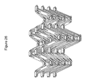
FIG. 26 shows a multi-layered expandable panel based upon two-layer, eight-axle joint bodies; and
FIG. 27 illustrates a collapsible-expandable panel based upon X-type auxetic unit cells.
DETAILED DESCRIPTION OF THE INVENTION
This invention improves upon rapidly deployable structures by providing components based upon negative Poisson's ratio (NPR) auxetic designs. FIGS. 1 and 2 illustrate a first such design based upon a “nested-V” configuration. FIG. 1 shows the structure in an expanded form, whereas FIG. 2 shows the structure in a collapsed state. In the collapsed state of FIG. 2, the structure assumes a width (W) reduction on the order of 70%. Being an auxetic in nature, a height (H) reduction is also evident from the diagrams.
The configuration of FIGS. 1, 2 is based upon an array of unit cells, each of which includes two shorter members (i.e., A, B) connected by joint bodies 102 forming a smaller V-shape and two longer members (i.e., C, D), also connected by joints, forming a larger V-shape. In the preferred embodiments members A, B are substantially the same length, as are members C, D, and all of the members are straight. However, in alternative embodiments the members may be of different lengths and may be curved or otherwise ‘non-straight.’ Note in the expanded state of FIG. 1 that the nested V-shapes are nearly triangular, while in the collapsed state of FIG. 2 the members associated with each unit cell assume a more parallel arrangement wherein the sides of the members are proximate to one another, if not touching in some cases. It is also worth noting that in this and other designs, some of the members form substantially parallel lines 150, 152, 154, 156 in the expanded state.
To provide a structural building element such as a wall component, a fabric 104 or other cover may be attached to the V-shapes, preferably at the joints 102, so as to realize a panel structure that may readily expand and collapse. Alternatively, the fabric material may be bonded to the sides of the various members. Although only one fabric sheet is depicted in FIGS. 1 and 2, a second sheet may be provided on the opposing side, thereby creating a trapped air space which may be filled with insulative material(s). As seen in FIG. 1, in the expanded state the flexible sheet is substantially unfolded, whereas in the collapsed states of FIG. 2, the sheet is folded along with the structure itself.
The members and joint bodies may be made out of any suitable material such as plastics, metals or wood. The members may be solid or hollow. Any type of fabric may be used, including canvas, nylon, and so forth. In lightweight implementations for shelters, tents, and the like, one preferred combination comprises aluminum interconnecting members, aluminum or plastic joint bodies, and rip-stop nylon fabric.
FIG. 3 is a more detailed diagram which better illustrates the way in which the unit cells are constructed and how they interact. Note that while this description may use terms such as upper, lower, right, left, lateral, vertical, inverted, forward, rear, etc., the reader should understand that these are for description only and that all of the structures disclosed herein may be oriented in any direction. Unit cell 10, in the middle of FIG. 3, includes upper members A, B and lower members C, D. Members A, B are connected with joint 112, members C, D are connected with joint 132, members A, C are connected with joint 102, and members B, D are connected with joint 122. In this case, all of the joint bodies 102, 112, 122, 132 may be the same.
Each member is pivotally coupled to two joints, one at each respective end of each member. Using joint 102 as an example, the joint includes two opposing connection points 104, 106 for shorter members and two connection points 108, 110 for longer members. These connections may be made in any appropriate manner, including nuts and bolts, rivets, spring pins or, as shown in subsequent Figures, with spring-action, clip-on arrangements.
Note that in FIG. 3, unit cell 10 shares its two longer members with inverted cells 90, 50 on either side. Unit cell 10 further shares its shorter member A with member A of cell 20, and shares its shorter member B with member B of cell 40. Unit cell 10 further shares its shorter member A with member A of invented cell 20, and shares its shorter member B with member B of inverted cell 40. In addition, joint 112 is shared by cells 10, 20, 30, 40; joint 132 is shared by cells 10, 50, 70, 90, and so on.
FIG. 4A is an oblique drawing of a body 102′ similar to that shown in FIG. 3, but with additional connection points to achieve additional structural arrangements. The body, which may be made of any hard, durable material such as metal or plastic, includes an upper portion 109 with connection points 108, 110, and two side extensions 103, 105 with connection points 104, 106. Forward and rear extensions 405, 407 with connection points 402, 404 allow the connections with the members to be flush as shown in the top-down and oblique views of FIGS. 4B and 4C.
FIG. 5 depicts the way in which an interconnecting member 502 may snap into a joint body 504. In this case the ends of the member 502 are temporarily spread apart enabling projections, posts or pins 506, 508 to be received by opposing openings in the body 504 represented by the axis 510 of a hole through the body. Note that the hole need not penetrate entirely through the body so long as appropriate corresponding depressions, recesses, or cavitations are provided.
As mentioned, for larger structures, geometries may be adjusted to suit different applications. For example, as shown in FIG. 6, an auxetic panel measuring just 1 foot by 4 feet may be expanded into a wall panel measuring 10 feet by 8 feet. Once expanded, the panels may be joined through any appropriate edge connections to produce walls for buildings, ceilings, and so forth.
FIG. 7 shows an auxetic panel based upon a different type of unit cell, in this case an X- or “bowtie” shape. The figure shows the panel in the contract and expanded conditions. As in FIG. 6, such a panel measuring just 1 foot by 4 feet may be expanded into a wall panel measuring 10 feet by 8 feet. Further, as with the array of V-shapes, some of the members of the bowtie configuration form substantially parallel lines 702, 704, etc. upon assuming the expanded configuration.
FIG. 8 depicts the nested-V cell used in a cylindrical configuration to construct a honeycomb auxetic beam, in this case having a generally hexagonal cross section. Such beams may be used in conjunction with the panels described herein to hold up roof structures, for example. As with the panel structures, the outside and/or inside surfaces of such beams may be fabric-covered.
As shown in FIG. 9, square, octagonal and other cross-sectional shapes are possible for beam constructions. FIG. 9A shows an expanded auxetic beam having a square cross section; FIG. 9B shows an expanded auxetic beam having a hexagonal or honeycomb cross section; FIG. 9C shows an expanded auxetic beam having an octagonal cross section; and FIG. 9D shows an expanded auxetic beam having a 10-sided cross section;
FIGS. 10A-10C illustrate a beam unfolding mechanism. In FIG. 10A, in the folded mode the beam may only be a foot long. The structure undergoes expansion in all directions in FIG. 10B, leading to a fully expanded shape in FIG. 10C that may be used for Quonset-type huts, tents, and other such structures. FIG. 11 illustrates the unfolding of an X-type auxetic beam.
FIG. 12 shows a curved expandable beam with variable NPR cells along the circle. With this transition in differently sized unit cells, either a straight beam may be constructed, as shown in FIG. 12, as illustrated in FIG. 13, the beam may form a curved shape by properly distributing variable NPR cells around a circle.
FIG. 14 illustrates the general concept for the joint. In particular, FIG. 14A is a top view of an alternative N-axle joint body, and FIG. 14B is a side view of the joint body of FIG. 14A showing how M layers may be provided. In this context, M layers refers to different levels or planes which, in the preferred embodiments are substantially parallel to one another. Each of the joint bodies shown in FIG. 14 may utilize any number of different joint types as shown in the diagram of FIG. 15; for example, joint types having male-female, female-female, female-male and male-male interconnection configurations. Extensions Jn-Jjt1 may be at the same or different angles θni.
FIGS. 16 and 17 illustrate various possible clicking joints constructed in accordance with the invention, while FIG. 18 illustrates different types of pin connection features. FIG. 19 shows examples of possible one-layer joints, and FIG. 20 shows examples of possible two-layer joints. FIG. 21 depicts joint bodies having up to 4 layers with the understanding that additional level are possible with sufficient stepped outer profiling.
In terms of specific structures, FIG. 23 depicts an expandable panel based upon a two-layer, eight-axle joint bodies, and FIG. 24 shows how the structure of FIG. 23 may be formed into an arch configuration. FIG. 25 depicts expandable beams based upon two-layer, four-axle joint bodies, and FIG. 26 shows a multi-layered expandable panel based upon two-layer, eight-axle joint bodies.
It will be appreciated that multiple variations are possible beyond the structures so far described. As previously described, FIG. 27 illustrates a collapsible-expandable panel based upon X-type auxetic unit cells. The members defining the expandable structure linkages may use different for “stuffer” members and “tensor” members, with dimensions d1-d5, shapes, topologies, cross-sections t1-t2, angles θ12, and material usages being defined by the intended application. The members defining the expandable structure may be made of ‘active’ materials, including shape-memory alloys such as Nitinol. Further, the members defining the expandable structure may include actuators and mechanical or electronic locking provisions associated with the joints and/or linkages.

Claims (23)

I claim:
1. An expandable-collapsible structure, comprising:
a plurality of joint bodies, each joint body having a plurality of connection features;
a plurality of interconnecting link members with opposing ends, each end including connection features that engage with the connection features of the joint bodies such that the link members pivot about different axes relative to the joint bodies, thereby forming an expandable and collapsible structure having a height and a width;
wherein the link members form an array of geometric unit cells, each unit cell comprising nested, expanding and contracting upper and lower V shapes;
wherein each upper V shape includes first and second upper members A, B interconnected with an upper joint body, and each lower V shape includes first and second lower members C, D interconnected with a lower joint body, wherein the first upper member (A) and the first lower member (C) are interconnected through a first side joint body, and the second upper member (B) and the second lower member (D), are connected to a second side joint body, wherein the upper members A, B are the same length, and the lower members C, D are the same length but longer that the upper members A, B, such that the upper joint body is disposed directly above the lower joint body forming a nested-V unit cell, and wherein the upper, lower and side joint bodies are further connected to additional, respective nested V unit cells forming an auxetic structure; and
wherein the height and the width of the structure when expanded are both greater than the height and the width of the structure when collapsed.
2. The structure of claim 1, wherein some of the interconnecting link members form parallel, straight lines when the structure is expanded.
3. The structure of claim 1, wherein the interconnecting link members have side edges which are proximate to one another or touching only when the structure is collapsed.
4. The structure of claim 1, wherein the interconnecting link members are rigid or flexible.
5. The structure of claim 1, wherein the interconnecting link members are straight or curved.
6. The structure of claim 1, wherein the interconnecting link members have uniform or varied cross sections.
7. The structure of claim 1, wherein the joint bodies with the connection features that provide pivot axes arranged on different levels or planes.
8. The structure of claim 1, further including a flexible sheet of material adhered to the joint bodies, link members, or both, thereby forming a covered panel when the structure is expanded.
9. The structure of claim 1, further including:
a flexible sheet of material adhered to the joint bodies, link members, or both, thereby forming a covered panel when the structure is expanded; and
wherein the material is waterproof or weather-resistant.
10. The structure of claim 1, further including:
a plurality of panels form by adhering a flexible sheet of material adhered to the joint bodies, link members, or both; and
wherein the panels are arranged to form a building, tent, shelter, storage unit, mobile house, vehicle body or other enclosure.
11. The structure of claim 1, wherein the connection features that provide one or more of the following different physical configurations:
the joint body connection features disposed on multiple layers, planes or levels,
the joint body connection features extending radially outwardly at a plurality of different angles,
the connection features between the joint bodies and the interconnecting link members being male-female, female-female, female-male or male-male, and
the connection features between the joint bodies and the interconnecting link members being pin-type connections.
12. The structure of claim 1, wherein the connection features are posts or projections and holes or recesses configured to receive the posts or projections.
13. The structure of claim 1, wherein the connection features include pins disposed along the pivot axes.
14. The structure of claim 1, wherein:
the ends of the link members include two arms with connection features; and
the arms are temporarily spread apart to engage with the connection features on the joint bodies.
15. The structure of claim 1, wherein:
the link members form an array of geometric unit cells having a periodicity when the structure is expanded; and
the periodicity varies in one or more dimensions.
16. The expandable structure of claim 1, wherein:
the number of unit cells within a layer of unit cells defines a height of the layer; and
unit cells in all layers have the same height.
17. The expandable structure of claim 1, wherein:
the number of unit cells within a layer of unit cells defines a height of the layer; and
the unit cells in different layers have the different heights.
18. The expandable structure of claim 1, wherein:
the number of unit cells within a layer of unit cells defines a height of the layer; and
the unit cells in the same layer have the different heights.
19. The expandable structure of claim 1, wherein:
the unit cells defines a width when the structure is expanded; and
the width is uniform or variable in one or more dimensions.
20. The expandable structure of claim 1, wherein the link members defining the expandable structure are constructed from metals, ceramics, fiber-reinforced composite materials, polymer matrix materials, plastics, or fibers.
21. The expandable structure of claim 1, further including foam or other filler material surrounding the link members.
22. The expandable structure of claim 1, wherein:
the structure has an outermost surface when expanded; and
the outermost surface is cylindrical or curved in multiple dimensions.
23. The expandable structure of claim 1, wherein:
the link members have cross sections; and
the cross sections define solid or hollow rods or tubes, flat or curved plates or strips, or U-shaped, T-shaped, V-shaped or I-shaped beams.
US13/650,841 2011-10-13 2012-10-12 Rapidly deployable structures based upon negative poisson's ratio (NPR) auxetic components Active 2033-01-11 US9376796B2 (en)

Priority Applications (1)

Application Number Priority Date Filing Date Title
US13/650,841 US9376796B2 (en) 2011-10-13 2012-10-12 Rapidly deployable structures based upon negative poisson's ratio (NPR) auxetic components

Applications Claiming Priority (2)

Application Number Priority Date Filing Date Title
US201161546834P 2011-10-13 2011-10-13
US13/650,841 US9376796B2 (en) 2011-10-13 2012-10-12 Rapidly deployable structures based upon negative poisson's ratio (NPR) auxetic components

Publications (2)

Publication Number Publication Date
US20130322955A1 US20130322955A1 (en) 2013-12-05
US9376796B2 true US9376796B2 (en) 2016-06-28

Family

ID=49670433

Family Applications (1)

Application Number Title Priority Date Filing Date
US13/650,841 Active 2033-01-11 US9376796B2 (en) 2011-10-13 2012-10-12 Rapidly deployable structures based upon negative poisson's ratio (NPR) auxetic components

Country Status (1)

Country Link
US (1) US9376796B2 (en)

Cited By (2)

* Cited by examiner, † Cited by third party
Publication number Priority date Publication date Assignee Title
US20180311833A1 (en) * 2017-04-27 2018-11-01 Massachusetts Institute Of Technology Non-planar shearing auxetic structures, devices, and methods
US10315459B2 (en) 2015-07-13 2019-06-11 Mkp Structural Design Associates, Inc. Ultralightweight airless ATV wheels based upon negative Poisson ratio (NPR) auxetic structures

Families Citing this family (20)

* Cited by examiner, † Cited by third party
Publication number Priority date Publication date Assignee Title
US9416839B2 (en) 2012-07-12 2016-08-16 Mkp Structural Design Associates, Inc. Bushings and bumpers based upon NPR (negative poisson's ratio) structures
US9538811B2 (en) * 2013-09-18 2017-01-10 Nike, Inc. Sole structure with holes arranged in auxetic configuration
US9554620B2 (en) * 2013-09-18 2017-01-31 Nike, Inc. Auxetic soles with corresponding inner or outer liners
CA2961625A1 (en) 2016-06-02 2017-12-02 The Royal Institution For The Advancement Of Learning/Mcgill University Bistable auxetics
US10180000B2 (en) 2017-03-06 2019-01-15 Isotruss Industries Llc Composite lattice beam
US10584491B2 (en) * 2017-03-06 2020-03-10 Isotruss Industries Llc Truss structure
ES2924523T3 (en) * 2017-12-01 2022-10-07 Airbus Operations Sl Deformable auxetic structure and manufacturing procedure
USD895157S1 (en) 2018-03-06 2020-09-01 IsoTruss Indsutries LLC Longitudinal beam
USD896401S1 (en) 2018-03-06 2020-09-15 Isotruss Industries Llc Beam
US11408216B2 (en) 2018-03-20 2022-08-09 Divergent Technologies, Inc. Systems and methods for co-printed or concurrently assembled hinge structures
US11590727B2 (en) * 2018-05-21 2023-02-28 Divergent Technologies, Inc. Custom additively manufactured core structures
US11608632B2 (en) * 2019-01-28 2023-03-21 William E. Smith Pre-stressed sinusoidal member in assembly and applications
US11959277B1 (en) 2019-01-28 2024-04-16 William E. Smith Pre-stressed sinusoidal member in assembly and applications
CN110077345A (en) * 2019-04-22 2019-08-02 南京理工大学 A kind of negative poisson's ratio car crass energy-absorption box
CN110553135A (en) * 2019-09-18 2019-12-10 汕头大学 Truss structure with adjustable mechanical property and manufacturing method thereof
US11255356B2 (en) 2019-09-26 2022-02-22 The Regents Of The University Of Michigan Fluidic actuator system using auxetic beam reinforcements
CN111696442B (en) * 2020-06-17 2022-04-01 合肥维信诺科技有限公司 Flexible screen folding cover plate, preparation method thereof and flexible display module
CN113343371B (en) * 2021-01-29 2022-07-15 北京理工大学重庆创新中心 Design method of foam-filled negative Poisson's ratio composite structure
CN113153073B (en) * 2021-04-19 2022-12-06 福建厚德节能科技发展有限公司 Evaporate and press waterproof windowsill of aerated concrete
CN115819974B (en) * 2022-11-15 2023-11-14 华南理工大学 Composite material structural system with customizable mechanical properties and preparation method

Citations (25)

* Cited by examiner, † Cited by third party
Publication number Priority date Publication date Assignee Title
US3675667A (en) 1970-09-25 1972-07-11 Jack V Miller Self-erecting tent
US3771274A (en) * 1972-05-30 1973-11-13 Gen Dynamics Corp Expandable retractable structure
US3968808A (en) * 1974-11-06 1976-07-13 Zeigler Theodore Richard Collapsible self-supporting structure
US4241746A (en) * 1979-05-02 1980-12-30 Bruce Rothe Collapsible building structure
US4471548A (en) * 1981-10-15 1984-09-18 John Goudie Associates, Inc. Display frames
US4475323A (en) * 1982-04-30 1984-10-09 Martin Marietta Corporation Box truss hoop
US4539786A (en) * 1983-03-03 1985-09-10 Ltv Aerospace And Defense Co. Biaxial scissors fold, post tensioned structure
US4655022A (en) * 1984-07-12 1987-04-07 Japan Aircraft Mfg. Co., Ltd. Jointed extendible truss beam
US4707953A (en) 1983-03-30 1987-11-24 Brunswick Corporation Expandable shelter system providing collective protection
US4901481A (en) 1988-11-21 1990-02-20 Seeley Jr Jesse R Inflatable shelter apparatus
US5184444A (en) * 1991-08-09 1993-02-09 Aec-Able Engineering Co., Inc. Survivable deployable/retractable mast
US5228258A (en) * 1989-11-27 1993-07-20 Fuji Jukogyo Kabushiki Kaisha Collapsible truss structure
US5921388A (en) 1998-11-25 1999-07-13 The United States As Represented By The Secretary Of Agriculture Quick deployment fire shelter
US6141934A (en) * 1998-12-07 2000-11-07 World Shelters, Inc. Folding frame system with foldable leg assembly and method of erecting a folding frame system
US6192633B1 (en) 1999-09-10 2001-02-27 Clint J. Hilbert Rapidly deployable protective enclosure
US6360760B1 (en) 1999-12-03 2002-03-26 Billwin Auto Accessories Limited Self-erecting and collapsible shelter
US6892744B2 (en) 2001-03-26 2005-05-17 Thomas G. Feldpausch Collapsible shelter structure
US20050115186A1 (en) * 2000-07-28 2005-06-02 Jensen David W. Iso-truss structure
WO2005079146A2 (en) 2004-02-11 2005-09-01 International Property Rights Ltd. Rapidly deployable temporary modular structures and component elements thereof
US20070044415A1 (en) * 2005-08-29 2007-03-01 Donald Merrifield Deployable triangular truss beam with orthogonally-hinged folding diagonals
US7533681B2 (en) * 2001-04-23 2009-05-19 Miller Stephen F Collapsible structural frame
US7644721B2 (en) 2005-01-14 2010-01-12 Charles Hoberman Synchronized four-bar linkages
US20100119792A1 (en) * 2008-11-10 2010-05-13 Zheng-Dong Ma Three-dimensional auxetic structures and applications thereof
US20100126545A1 (en) 2008-11-25 2010-05-27 Bullivant Todd J Rapidly deployable military vehicle repair facility
US7941974B2 (en) 2006-11-28 2011-05-17 Vanbasten Willem F Inflatable shelter for use in hostile environment

Patent Citations (29)

* Cited by examiner, † Cited by third party
Publication number Priority date Publication date Assignee Title
US3675667A (en) 1970-09-25 1972-07-11 Jack V Miller Self-erecting tent
US3771274A (en) * 1972-05-30 1973-11-13 Gen Dynamics Corp Expandable retractable structure
US3968808A (en) * 1974-11-06 1976-07-13 Zeigler Theodore Richard Collapsible self-supporting structure
US4241746A (en) * 1979-05-02 1980-12-30 Bruce Rothe Collapsible building structure
US4471548A (en) * 1981-10-15 1984-09-18 John Goudie Associates, Inc. Display frames
US4475323A (en) * 1982-04-30 1984-10-09 Martin Marietta Corporation Box truss hoop
US4539786A (en) * 1983-03-03 1985-09-10 Ltv Aerospace And Defense Co. Biaxial scissors fold, post tensioned structure
US4707953A (en) 1983-03-30 1987-11-24 Brunswick Corporation Expandable shelter system providing collective protection
US4655022A (en) * 1984-07-12 1987-04-07 Japan Aircraft Mfg. Co., Ltd. Jointed extendible truss beam
US4901481A (en) 1988-11-21 1990-02-20 Seeley Jr Jesse R Inflatable shelter apparatus
US5228258A (en) * 1989-11-27 1993-07-20 Fuji Jukogyo Kabushiki Kaisha Collapsible truss structure
US5184444A (en) * 1991-08-09 1993-02-09 Aec-Able Engineering Co., Inc. Survivable deployable/retractable mast
US5921388A (en) 1998-11-25 1999-07-13 The United States As Represented By The Secretary Of Agriculture Quick deployment fire shelter
US6141934A (en) * 1998-12-07 2000-11-07 World Shelters, Inc. Folding frame system with foldable leg assembly and method of erecting a folding frame system
US6192633B1 (en) 1999-09-10 2001-02-27 Clint J. Hilbert Rapidly deployable protective enclosure
US6360760B1 (en) 1999-12-03 2002-03-26 Billwin Auto Accessories Limited Self-erecting and collapsible shelter
US20050115186A1 (en) * 2000-07-28 2005-06-02 Jensen David W. Iso-truss structure
US6892744B2 (en) 2001-03-26 2005-05-17 Thomas G. Feldpausch Collapsible shelter structure
US7533681B2 (en) * 2001-04-23 2009-05-19 Miller Stephen F Collapsible structural frame
WO2005079146A2 (en) 2004-02-11 2005-09-01 International Property Rights Ltd. Rapidly deployable temporary modular structures and component elements thereof
US7389621B2 (en) 2004-02-11 2008-06-24 International Property Rights Ltd. Rapidly deployable temporary modular structures and component elements thereof
US7578111B2 (en) 2004-02-11 2009-08-25 Hawes Raymond W Rapidly deployable temporary modular structures and component elements thereof
US7644721B2 (en) 2005-01-14 2010-01-12 Charles Hoberman Synchronized four-bar linkages
US20070044415A1 (en) * 2005-08-29 2007-03-01 Donald Merrifield Deployable triangular truss beam with orthogonally-hinged folding diagonals
US7963084B2 (en) * 2005-08-29 2011-06-21 Donald Merrifield Deployable triangular truss beam with orthogonally-hinged folding diagonals
US7941974B2 (en) 2006-11-28 2011-05-17 Vanbasten Willem F Inflatable shelter for use in hostile environment
US20100119792A1 (en) * 2008-11-10 2010-05-13 Zheng-Dong Ma Three-dimensional auxetic structures and applications thereof
US7910193B2 (en) 2008-11-10 2011-03-22 Mkp Structural Design Associates, Inc. Three-dimensional auxetic structures and applications thereof
US20100126545A1 (en) 2008-11-25 2010-05-27 Bullivant Todd J Rapidly deployable military vehicle repair facility

Cited By (3)

* Cited by examiner, † Cited by third party
Publication number Priority date Publication date Assignee Title
US10315459B2 (en) 2015-07-13 2019-06-11 Mkp Structural Design Associates, Inc. Ultralightweight airless ATV wheels based upon negative Poisson ratio (NPR) auxetic structures
US20180311833A1 (en) * 2017-04-27 2018-11-01 Massachusetts Institute Of Technology Non-planar shearing auxetic structures, devices, and methods
US10850406B2 (en) * 2017-04-27 2020-12-01 Massachusetts Institute Of Technology Non-planar shearing auxetic structures, devices, and methods

Also Published As

Publication number Publication date
US20130322955A1 (en) 2013-12-05

Similar Documents

Publication Publication Date Title
US9376796B2 (en) Rapidly deployable structures based upon negative poisson's ratio (NPR) auxetic components
US5244001A (en) Collapsible canopy framework having captured scissor ends with non-compressive pivots
CA2750824C (en) Collapsible shelters with and without a floating hub
US4539786A (en) Biaxial scissors fold, post tensioned structure
US5016418A (en) Synchronously deployable double fold beam and planar truss structure
JP3062246B2 (en) Polyhedral building system
US3445970A (en) Right triangular building components
US20110252717A1 (en) Foldable structures for a construction
JPH0830362B2 (en) Arch dome reinforced with tension material and its construction method
US20100058704A9 (en) Deployable structures
WO2008021980A2 (en) Modular frame with parabolic top
US2803317A (en) Structural space frames
US4637192A (en) Telescoping support structure
JP2011527390A (en) Support structure system
Hernandez Deployable Estructures
US3325958A (en) Preassembled structural framework
US4277922A (en) Frame assembly apparatus and method of making same
JPH01214644A (en) Tetrahedral body module structure for house
JP2012122244A (en) Roof structure and construction method for the same
US3964216A (en) Modular building constructon
WO1997044543A1 (en) Frame structure and method for forming the same
US4150516A (en) Framework and sheet material building structure
Pérez-Valcárcel et al. Expandable bar structures for emergency situations
WO2001027416A1 (en) Building structure framework for protecting stage structure
CN112458870B (en) Novel expandable bridge structure based on paper folding structure

Legal Events

Date Code Title Description
AS Assignment

Owner name: MKP STRUCTURAL DESIGN ASSOCIATES, INC., MICHIGAN

Free format text: ASSIGNMENT OF ASSIGNORS INTEREST;ASSIGNOR:MA, ZHENG-DONG;REEL/FRAME:029125/0720

Effective date: 20121009

STCF Information on status: patent grant

Free format text: PATENTED CASE

MAFP Maintenance fee payment

Free format text: PAYMENT OF MAINTENANCE FEE, 4TH YR, SMALL ENTITY (ORIGINAL EVENT CODE: M2551); ENTITY STATUS OF PATENT OWNER: SMALL ENTITY

Year of fee payment: 4

FEPP Fee payment procedure

Free format text: MAINTENANCE FEE REMINDER MAILED (ORIGINAL EVENT CODE: REM.); ENTITY STATUS OF PATENT OWNER: SMALL ENTITY