US9381396B2 - Portable progressive resistance exercise device - Google Patents

Portable progressive resistance exercise device Download PDF

Info

Publication number
US9381396B2
US9381396B2 US14/612,686 US201514612686A US9381396B2 US 9381396 B2 US9381396 B2 US 9381396B2 US 201514612686 A US201514612686 A US 201514612686A US 9381396 B2 US9381396 B2 US 9381396B2
Authority
US
United States
Prior art keywords
cylinder
front frame
arm
training device
distal end
Prior art date
Legal status (The legal status is an assumption and is not a legal conclusion. Google has not performed a legal analysis and makes no representation as to the accuracy of the status listed.)
Active
Application number
US14/612,686
Other versions
US20150217158A1 (en
Inventor
Peter V Colan
Patrick T Kulwicki
Current Assignee (The listed assignees may be inaccurate. Google has not performed a legal analysis and makes no representation or warranty as to the accuracy of the list.)
FEEDBACK SPORTS LLC
Original Assignee
SportCrafters Inc
Priority date (The priority date is an assumption and is not a legal conclusion. Google has not performed a legal analysis and makes no representation as to the accuracy of the date listed.)
Filing date
Publication date
Application filed by SportCrafters Inc filed Critical SportCrafters Inc
Priority to US14/612,686 priority Critical patent/US9381396B2/en
Assigned to SportCrafters, Inc. reassignment SportCrafters, Inc. ASSIGNMENT OF ASSIGNORS INTEREST (SEE DOCUMENT FOR DETAILS). Assignors: KULWICKI, PATRICK T, COLAN, PETER V
Publication of US20150217158A1 publication Critical patent/US20150217158A1/en
Application granted granted Critical
Publication of US9381396B2 publication Critical patent/US9381396B2/en
Assigned to FEEDBACK SPORTS LLC reassignment FEEDBACK SPORTS LLC ASSIGNMENT OF ASSIGNORS INTEREST (SEE DOCUMENT FOR DETAILS). Assignors: SportCrafters, Inc.
Active legal-status Critical Current
Anticipated expiration legal-status Critical

Links

Images

Classifications

    • AHUMAN NECESSITIES
    • A63SPORTS; GAMES; AMUSEMENTS
    • A63BAPPARATUS FOR PHYSICAL TRAINING, GYMNASTICS, SWIMMING, CLIMBING, OR FENCING; BALL GAMES; TRAINING EQUIPMENT
    • A63B22/00Exercising apparatus specially adapted for conditioning the cardio-vascular system, for training agility or co-ordination of movements
    • A63B22/06Exercising apparatus specially adapted for conditioning the cardio-vascular system, for training agility or co-ordination of movements with support elements performing a rotating cycling movement, i.e. a closed path movement
    • A63B22/0605Exercising apparatus specially adapted for conditioning the cardio-vascular system, for training agility or co-ordination of movements with support elements performing a rotating cycling movement, i.e. a closed path movement performing a circular movement, e.g. ergometers
    • AHUMAN NECESSITIES
    • A63SPORTS; GAMES; AMUSEMENTS
    • A63BAPPARATUS FOR PHYSICAL TRAINING, GYMNASTICS, SWIMMING, CLIMBING, OR FENCING; BALL GAMES; TRAINING EQUIPMENT
    • A63B69/00Training appliances or apparatus for special sports
    • A63B69/16Training appliances or apparatus for special sports for cycling, i.e. arrangements on or for real bicycles
    • AHUMAN NECESSITIES
    • A63SPORTS; GAMES; AMUSEMENTS
    • A63BAPPARATUS FOR PHYSICAL TRAINING, GYMNASTICS, SWIMMING, CLIMBING, OR FENCING; BALL GAMES; TRAINING EQUIPMENT
    • A63B21/00Exercising apparatus for developing or strengthening the muscles or joints of the body by working against a counterforce, with or without measuring devices
    • A63B21/00058Mechanical means for varying the resistance
    • A63B21/00076Mechanical means for varying the resistance on the fly, i.e. varying the resistance during exercise
    • AHUMAN NECESSITIES
    • A63SPORTS; GAMES; AMUSEMENTS
    • A63BAPPARATUS FOR PHYSICAL TRAINING, GYMNASTICS, SWIMMING, CLIMBING, OR FENCING; BALL GAMES; TRAINING EQUIPMENT
    • A63B21/00Exercising apparatus for developing or strengthening the muscles or joints of the body by working against a counterforce, with or without measuring devices
    • A63B21/005Exercising apparatus for developing or strengthening the muscles or joints of the body by working against a counterforce, with or without measuring devices using electromagnetic or electric force-resisters
    • A63B21/0051Exercising apparatus for developing or strengthening the muscles or joints of the body by working against a counterforce, with or without measuring devices using electromagnetic or electric force-resisters using eddy currents induced in moved elements, e.g. by permanent magnets
    • AHUMAN NECESSITIES
    • A63SPORTS; GAMES; AMUSEMENTS
    • A63BAPPARATUS FOR PHYSICAL TRAINING, GYMNASTICS, SWIMMING, CLIMBING, OR FENCING; BALL GAMES; TRAINING EQUIPMENT
    • A63B24/00Electric or electronic controls for exercising apparatus of preceding groups; Controlling or monitoring of exercises, sportive games, training or athletic performances
    • A63B24/0087Electric or electronic controls for exercising apparatus of groups A63B21/00 - A63B23/00, e.g. controlling load
    • A63B2024/0093Electric or electronic controls for exercising apparatus of groups A63B21/00 - A63B23/00, e.g. controlling load the load of the exercise apparatus being controlled by performance parameters, e.g. distance or speed
    • AHUMAN NECESSITIES
    • A63SPORTS; GAMES; AMUSEMENTS
    • A63BAPPARATUS FOR PHYSICAL TRAINING, GYMNASTICS, SWIMMING, CLIMBING, OR FENCING; BALL GAMES; TRAINING EQUIPMENT
    • A63B69/00Training appliances or apparatus for special sports
    • A63B69/16Training appliances or apparatus for special sports for cycling, i.e. arrangements on or for real bicycles
    • A63B2069/161Training appliances or apparatus for special sports for cycling, i.e. arrangements on or for real bicycles supports for the front of the bicycle
    • A63B2069/163Training appliances or apparatus for special sports for cycling, i.e. arrangements on or for real bicycles supports for the front of the bicycle for the front wheel
    • AHUMAN NECESSITIES
    • A63SPORTS; GAMES; AMUSEMENTS
    • A63BAPPARATUS FOR PHYSICAL TRAINING, GYMNASTICS, SWIMMING, CLIMBING, OR FENCING; BALL GAMES; TRAINING EQUIPMENT
    • A63B69/00Training appliances or apparatus for special sports
    • A63B69/16Training appliances or apparatus for special sports for cycling, i.e. arrangements on or for real bicycles
    • A63B2069/167Training appliances or apparatus for special sports for cycling, i.e. arrangements on or for real bicycles on rollers without further support
    • AHUMAN NECESSITIES
    • A63SPORTS; GAMES; AMUSEMENTS
    • A63BAPPARATUS FOR PHYSICAL TRAINING, GYMNASTICS, SWIMMING, CLIMBING, OR FENCING; BALL GAMES; TRAINING EQUIPMENT
    • A63B69/00Training appliances or apparatus for special sports
    • A63B69/16Training appliances or apparatus for special sports for cycling, i.e. arrangements on or for real bicycles
    • A63B2069/168Force transfer through the rim of the wheel
    • AHUMAN NECESSITIES
    • A63SPORTS; GAMES; AMUSEMENTS
    • A63BAPPARATUS FOR PHYSICAL TRAINING, GYMNASTICS, SWIMMING, CLIMBING, OR FENCING; BALL GAMES; TRAINING EQUIPMENT
    • A63B2210/00Space saving
    • A63B2210/50Size reducing arrangements for stowing or transport

Definitions

  • Bicycle rollers have been in use since the early 1900's.
  • a bicycle roller is a dynamometer for bicycles that is powered by the bicycle rider.
  • a portable bicycle roller is traditionally comprised of one or more rotatable cylinders positioned so that the rear wheel of the bicycle rides on at least one cylinder, and one of the axles of the bicycle is fixed for stability. In the typical application, the front wheel is removed and the front fork of the bicycle is fixed to prevent the rider from tipping over.
  • the amount of power, or wattage, that the bicyclist is required to exert to ride at a given speed on a bicycle roller was determined by the amount of rolling resistance resulting from tire distress as the tire rolls over each of the cylinders plus the wattage required to drive any external devices which exert resistance on one or more of the cylinders.
  • Rolling resistance is predominantly a function of the cylinder diameter, tire pressure, and bicyclist weight. Relying on these factors alone provides a linear relationship of resistance versus speed.
  • Simple devices that add a predictable amount of resistance such as the magnetic eddy-current device of U.S. Pat. No. 6,857,992 (incorporated herein by reference) can be added externally to the cylinders, but these are undesirable since they provide a linear speed-to-resistance relationship.
  • Prior art bicycle rollers have a linear relationship of speed versus resistance. This solution is unsatisfactory; when beginning to pedal the bike from rest on rollers, low resistance is desired to allow the wheels to accelerate quickly enough to enable sufficient steering dynamics to keep the bicycle stable on the rollers. However, to obtain a meaningful training session, a high amount of resistance is desired when pedaling at a rate suitable to achieve cardiovascular exercise benefit.
  • Eddy current devices use magnetism to generate electrical current in conductive materials when a magnetic field is placed in relative close proximity to the conductive material and relative motion of the magnet to the conductive material is present. The motion creates small electrical currents in the conductive material. The current creates a non-contacting friction between the two, along with generating heat in the conductive material. This heat must be dissipated in some fashion.
  • Prior art resistance trainers utilize a large surface area on the roller(s) to dissipate the heat that is generated during use. For portable devices, parts must be made smaller to facilitate transportation and storage. This leads to a heat management issue, Prior art used a cylinder that contacted the rider's tire on the exterior and had the eddy current friction mechanism on the interior.
  • the present disclosure describes an improved eddy current resistance device that fits into a smaller physical envelope, while still being able to provide the resistance of a much larger resistance device.
  • By creating a cavity between the outer wall that carries the mechanical load of the rider's tire and the inner wall that generates the heat it is possible to reduce overall size without compromising overall capacity.
  • fins directing air flow in the cavity between the outer and inner cylinder can be incorporated on the sides of the cylinder.
  • the inner and outer cylinder can be connected through support members between the outside diameter of the inner cylinder and the inside diameter of the outer cylinder. These support members can be incorporated as part of an extrusion that makes the cylinders and support members one piece.
  • the inner and outer cylinders can also be connected through the bearing support structure that allows the cylinders to rotate about the central axis. As such, a workable portable bicycle roller is desired.
  • the progressive resistance device described herein is applicable to other stationary trainers, such as those sold for use with bicycles, handcycles and tricycles (see U.S. Pat. Nos. 7,011,607, 7,585,258, 6,964,633, and 6,042,517, each incorporated herein by reference).
  • the progressive resistance device described herein is distinguishable from the magnetic resistance system for rollers (U.S. Pat. No. 6,857,992, incorporated herein by reference) in that the progressive resistance device automatically adjusts resistance level relative to speed, rather than being manually adjustable.
  • FIG. 1 is an isometric view of a bicycle attached to the device
  • FIG. 2 is an exploded isometric view of the device
  • FIG. 3 is an isometric view of the resistance device
  • FIG. 4 is a cross section of the device showing the magnet position vs cylinder speed
  • FIG. 5 is a cross section of the device showing the mechanical stop
  • FIG. 6 is a cross section of the device showing the return spring
  • FIG. 7 is a graph showing resistance vs speed
  • FIG. 8 is a side view of the device in the folded position
  • FIG. 9 is a side view of the device in the first step of unfolding
  • FIG. 10 is a side view of the device in the second step of unfolding
  • FIG. 11 is a side view of the device in the third step of unfolding
  • FIG. 12 is a side view of the device in the unfolded position
  • FIG. 13 is a top view of the device
  • FIG. 14 is a side view of the device
  • FIG. 15 is a bottom view of the device.
  • FIG. 16 is a partial section view of a support as stored in the front frame.
  • FIG. 17 is an assembled view of the device as shown in FIG. 2 .
  • the resistance device is shown with a driving mechanism, such as a bicycle 9 in FIG. 1 and the device as mounted on a training device 12 is shown in FIGS. 1 and 2 .
  • the progressive resistance device 10 is a conductive inner cylinder 14 ( FIG. 3 ), having an inner surface 15 defining an internal chamber 16 .
  • the inner cylinder 14 also has an outer wall 18 with an external surface 19 that circumscribes the first, defining an annular area 20 between the two.
  • One or more magnets 22 is carried on a pivotal magnet carrier 24 in proximity to inner surface 15 and housed within the internal chamber 16 .
  • Eddy currents produced in the inner cylinder 14 create a non-contacting frictional drag as the inner cylinder 14 spins relative to the magnet(s) 22 .
  • This drag causes a force that attempts to pull the magnet 22 from a resting position A (as shown in FIGS. 4-6 ) along with the rotation of the inner cylinder 14 .
  • the magnet 22 is mounted on a magnet carrier 24 that pivots on an axis 26 ( FIG. 6 ) that is eccentrically offset from the rotational axis 28 of the cylinder. This rotation alters the magnet's proximity to the inner surface 15 by pulling the magnet carrier 24 to move in an eccentric orientation as relates to the rotational axis 28 of the cylinder.
  • a torsional spring 35 ( FIG.
  • the pivotal position of the magnet carrier 24 to the inner cylinder 14 is closer as shown in position B and closer yet as shown in position C ( FIG. 5 ) as cylinder 14 speed increases.
  • Another benefit of the progressive resistance device described herein is that when a linear relationship between speed and resistance is desired, a rotational stop may be implemented on the pivotal magnet carrier so that pivotal angle is limited, preventing the magnet(s) 22 from getting closer to the inner cylinder 14 when the rotational direction of the cylinder is reversed.
  • the inner cylinder 14 can rotate in an opposite direction described above—allowing the same progressive resistance device 10 to provide either linear or proportional training depending on the direction of rotation of the inner cylinder 14 . With the progressive resistance device reversed, the result will be a linear relationship of speed and resistance. Therefore, the progressive resistance device 10 described herein is unique in that it allows the user to select progressive resistance or linear resistance, as desired.
  • the progressive resistance device is removable from the roller frame 61 ( FIG. 1 ) and is reversible, to allow the user to select linear or progressive resistance.
  • a trainer having a single progressive resistance device described herein may be adequate.
  • a bicycle roller can comprise more than one device 10
  • the use of one or two progressive resistance devices described herein may be used in the place of the roller's cylinders to achieve differing levels of resistance.
  • a second roller is simply an idler and provides little to no rolling resistance.
  • the second wall 18 and annular space 20 ( FIG. 3 ) between the two cylinders may be necessary to prevent excessive heat from reaching the surface where the external surface 19 meets the tire 8 .
  • the annular space 20 between the cylinders 14 , 18 can provide a thermal barrier between the cylinders and allow a cooling medium (typically air) through which it can pass to expel excessive heat.
  • the inner 14 and outer 18 cylinders are mechanically connected, either by support structure 34 ( FIG. 3 ) between the two or through the mounting of the cylinder to the axle through a bearing support 36 , 38 ( FIG. 3 ).
  • cooling fins 40 on the bearing supports 36 , 38 that mount the cylinders to the axle 30 can be implemented through the implementation of cooling fins 40 on the bearing supports 36 , 38 that mount the cylinders to the axle 30 .
  • the cooling fins 40 can be arranged on the bearing supports 36 , 38 in such a manner to direct the flow of the cooling medium from one end of the cylinder to the other, thereby pulling heat from the assembly as the rider uses the device.
  • One embodiment of the forced air cooling involves cooling fins 40 on the outer diameter of the bearing supports 36 , 38 that pull air in on one side and force it out on the other side. Since the cylinder only produces heat while it is in motion, any features that move air during rotation are effective without requiring additional complexity or parts.
  • Blades 40 integrated into the bearing supports pull cooler air in from one end of the cylinder and expel it through the opposite end. Cooling requirements may only dictate that one end of the cylinder incorporates fan shaped features to generate airflow.
  • An additional embodiment of this technology to achieve a higher level of resistance on a single cylinder, is to include stationary magnets on the outer side of the progressive resistance device placed and oriented when the progressive resistance device is at rest.
  • the poles of the moveable magnets inside the cylinder will oppose the stationary magnets outside the cylinder, thereby reducing the magnetic flux on the conductive cylinder wall and, when the progressive resistance device rotates during its normal operation, the moveable magnets inside the cylinder approach stationary magnets on the outside of the cylinder in such a way that the magnets are attracted by appropriate pole alignment; thereby increasing the magnetic flux on the conductive cylinder wall.
  • a portable roller-type stationary bicycle trainer 12 includes a cycle attachment 139 shown in FIG. 1 using a quick release bolt 140 for one axle of the bicycle or attachment portion, shown as a front fork 141 with supports 120 that extend outward to stabilize the rider and a narrow roller that is driven by the driving tire of the bicycle ( FIG. 1 ).
  • Configurations of attaching cylindrical rollers with a roller frame 61 intended to appropriately space the rollers and allow for adjustment of the cylinders for use with various bicycles may be employed.
  • a roller frame 61 includes oppositely located sides 60 that support the axles 30 of the cylinders.
  • the sides 60 have an upstanding portion 46 and a support portion 48 ( FIG. 1 ).
  • the upstanding portion 46 receives the progressive resistance devices 10 and affixes them using the axle 30 .
  • the opposing support portions 48 create a channel 33 as shown in FIG. 1 .
  • the roller frame 61 further includes a bolt 62 ( FIG. 2 ) that extends between sides of the frame to pivotally hold an arm 64 at an arm attaching point 63 .
  • the arm has a first portion 66 and a second portion 68 ( FIG. 12 ) that telescopingly slides over the first portion of the arm.
  • the arm 64 has an upper surface 32 and a lower surface 31 and includes pivot points 52 , 54 at each terminal end ( FIG. 11 ).
  • the pivot point 52 receives bolt 62 where it attaches to the roller frame 61 , specifically sides 60 .
  • Pivot point 52 is offset from the main axis of the arm.
  • the pivot point 54 is located oppositely and receives a bolt 94 ( FIG. 2 ).
  • the first portion 66 of the arm includes a bolt 70 ( FIGS. 1 and 2 ) that is fixed within the first portion.
  • the second portion 68 of the arm 64 includes a slot 74 that the bolt 70 slides within to allow telescoping.
  • the portions 66 , 68 of the arm 64 maybe slidingly adjusted and the nut 72 rotated to clamp them to a fixed and desired length.
  • the arm 66 is pivotally connected to a front frame member 76 .
  • the front frame member 76 is an extrusion having a constant cross section for most of its length.
  • the front frame member 76 includes two elongate tubes 80 that extend the length of the front frame member 76 .
  • Each tube 80 has a wall 82 with an inner surface 84 .
  • the tubes 80 are joined by a web 88 spanning between them on one side to form a flat side 90 ( FIG. 1 ).
  • Opposite the flat side 90 of the front frame member 76 is a groove 78 defined by the tubes 80 and the web 88 .
  • the web extends most of the length of the frame member 76 but is shortly less than the length of the tubes 80 and forms a notch 92 ( FIG. 16 ) that extends between the tubes 80 .
  • the arm 64 is pivotally connected to the front frame member 76 with a bolt 94 that extends through the tubes 80 that straddle the notch 92 .
  • the ends of the tubes 80 adjacent to the notch 92 receive plugs 124 .
  • the opposite ends of the tubes 80 are open.
  • Intermediate to the ends of the tubes 80 are a pair of transverse holes 102 .
  • the transverse holes 102 have a first aperture 104 that is formed through wall 82 of the tube diagonally opposite where the web 88 joins each tube 80 .
  • the transverse hole has a perimeter that is circular in cross section.
  • Each transverse hole 102 continues into its corresponding tube 80 to the inner surface 84 opposite the first aperture 104 to form a bottom portion of the transverse hole 102 .
  • the bottom portion of the hole 102 extends beyond the inner surface 84 but not through to the flat side 90 of the front frame.
  • a gusset that is integral to the web 88 and corresponding tube 80 .
  • the gusset adds thickness where the web 88 joins each tube 80 .
  • the gusset is useful to provide additional material near the bottom portion of each transverse hole 102 .
  • the bottom portion is a cylindrical depression within the wall 82 having a flat circular bottom and a cylindrical perimeter. Within the flat circular bottom is a centrally located tapped hole 134 . All shown in best detail on exploded FIG. 2 .
  • Legs 120 are made from round tubular aluminum but can be made from other structural materials.
  • One end of the leg 120 receives a plug 122 that provides a non-slip, non-marring end to the legs 120 that will rest on a floor.
  • the plug 122 is shown as a rounded end rubber plug.
  • the opposite end of the legs 120 are cut squarely to from a second end. From the center, near the second end of each leg 120 is an attaching end, shown as a threaded stud 128 extending therefrom.
  • the threaded stud 128 is designed to be screwed into a threaded hole 134 . When this is done, the transverse hole 102 sets an oblique angle between the legs 120 and the tubes 80 to which the legs 120 extend from.
  • the second end fits within the bottom portion of its corresponding transverse hole 102 and is supported laterally by the perimeter in the inner surface near the bottom portion.
  • the transverse hole 102 supports the leg 120 at a distance spaced from the bottom portion to provide a rigidly supported connection between the leg 120 and the front frame member 76 .
  • each tube 80 includes a threaded hole 117 also referred to as a receiver that receives the stud 128 so that the leg 120 may securely held within a tube 80 when threaded stud 128 is screwed into a corresponding threaded hole 117 .
  • the groove 78 is capable of receiving the arm 64 within it when the arm 64 is folded onto the front frame member 76 .
  • the arm 64 may be adjusted so that the length of the arm 64 locates the open ends of the tubes 80 adjacent to the pivot where the arm 64 is joined to the roller frame 61 . From this position, the front frame member 76 may be folded to the sides of the roller frame 61 opposite where the cylinders are mounted.
  • a quick release bolt 140 ( FIG. 2 ) is located near the open ends of the tubes 80 on the front frame member 76 .
  • the quick release is received into notches 142 ( FIG. 2 ) that are located between the pivot where the arm 64 is attached to the roller frame 61 and the cylinders.
  • the driven wheel of a bicycle When the progressive resistance device is used, the driven wheel of a bicycle is placed on the two rear cylinders and the front wheel of a bicycle may be removed and the front axle or fork is mounted using the bolt 140 to the front frame 76 that supports the front and stabilizes the bicycle frame.
  • the driven wheel of a bicycle is placed between the two roller cylinders and aligned in such a way that the tire of the bicycle, tricycle, or handcycle remains in contact with the roller cylinders during use.
  • the user pedals the bicycle, tricycle or handcycle so as to rotate the driven wheel which in turn rotates the cylinder or cylinders supporting the driven wheel.
  • the device 12 can be converted between a stored configuration and a use configuration.
  • the stored configuration is shown in FIGS. 13-15 .
  • the first step to convert the device 12 to the use configuration consists of freeing the legs 120 . This consists of unthreading the stud 128 from the threaded hole 117 and sliding the leg 120 from the tube 80 as shown in FIG. 8 .
  • the bolt 140 is loosened, freeing it from the notches 142 , the release of bolt 140 and pivoting of the arm 64 and front frame 76 are shown in FIG. 9 .
  • the next step involves pivoting the front frame 76 from the arm 64 . This is shown in FIG. 10 .
  • the next step is to secure the supports 120 in the transverse holes 102 .
  • FIG. 11 The next step is to affix a bicycle or similar device to the bolt 140 and lock it down to secure it.
  • the front fork of a bicycle is attached.
  • the arm 64 is adjusted by sliding the first portion 66 relative to second portion 68 in order to properly position the driving wheel of the bicycle or other device on the progressive resistance device 10 and the bolt 70 and nut 72 are used to fix the length of the arm 64 .
  • Proper positioning is shown in FIGS. 1 and 12 .
  • the training device 12 contacts the floor on plugs 122 and 124 and support portion 48 of the roller frame 61 .
  • the front frame 76 partially fits inside the channel that is created between the support portions 48 of the roller frame 61 .
  • the training device 12 can be fixed in the folded position by locking the bolt 140 in the notches 142 .
  • the front frame is visible, specifically flat side 90 . It is possible for the flat side 90 to directly contact the external surface 19 ( FIG. 3 ) of the progressive resistance device 10 .

Abstract

A collapsible folding training device is provided having a rear frame portion that contains a resistance device. The resistance device uses eddy currents and has a pivoting magnet internally that creates progressively increasing resistance as speed increases. An arm is attached to the rear frame portion that can pivot from a stored position to an in-use position. At the opposite end of the arm, a front frame is attached where it can affix a portion of a driving mechanism, such as a bicycle. The front frame supports and stabilizes the driving mechanism. The arm sets the distance between the front frame and the resistance device.

Description

CROSS REFERENCE TO RELATED APPLICATIONS
This application claims the benefit of U.S. Provisional Application No. 61/935,583, filed Feb. 4, 2014, the disclosures of which are hereby incorporated by reference.
BACKGROUND OF THE INVENTION
Bicycle rollers have been in use since the early 1900's. A bicycle roller is a dynamometer for bicycles that is powered by the bicycle rider. A portable bicycle roller is traditionally comprised of one or more rotatable cylinders positioned so that the rear wheel of the bicycle rides on at least one cylinder, and one of the axles of the bicycle is fixed for stability. In the typical application, the front wheel is removed and the front fork of the bicycle is fixed to prevent the rider from tipping over.
In the prior art, the amount of power, or wattage, that the bicyclist is required to exert to ride at a given speed on a bicycle roller was determined by the amount of rolling resistance resulting from tire distress as the tire rolls over each of the cylinders plus the wattage required to drive any external devices which exert resistance on one or more of the cylinders. Rolling resistance is predominantly a function of the cylinder diameter, tire pressure, and bicyclist weight. Relying on these factors alone provides a linear relationship of resistance versus speed. Simple devices that add a predictable amount of resistance such as the magnetic eddy-current device of U.S. Pat. No. 6,857,992 (incorporated herein by reference) can be added externally to the cylinders, but these are undesirable since they provide a linear speed-to-resistance relationship.
Prior art bicycle rollers have a linear relationship of speed versus resistance. This solution is unsatisfactory; when beginning to pedal the bike from rest on rollers, low resistance is desired to allow the wheels to accelerate quickly enough to enable sufficient steering dynamics to keep the bicycle stable on the rollers. However, to obtain a meaningful training session, a high amount of resistance is desired when pedaling at a rate suitable to achieve cardiovascular exercise benefit.
To achieve both objectives it is desired to have a progressive resistance relationship with speed. In other words, a non-linear relationship between speed and resistance where the slope of resistance versus speed increases with increasing speed. This relationship is preferred because it more effectively simulates the non-linear effect of combined rolling resistance and wind resistance experienced when riding a bicycle in traditional fashion.
Eddy current devices use magnetism to generate electrical current in conductive materials when a magnetic field is placed in relative close proximity to the conductive material and relative motion of the magnet to the conductive material is present. The motion creates small electrical currents in the conductive material. The current creates a non-contacting friction between the two, along with generating heat in the conductive material. This heat must be dissipated in some fashion. Prior art resistance trainers utilize a large surface area on the roller(s) to dissipate the heat that is generated during use. For portable devices, parts must be made smaller to facilitate transportation and storage. This leads to a heat management issue, Prior art used a cylinder that contacted the rider's tire on the exterior and had the eddy current friction mechanism on the interior. With a large surface area, along with a good thermal conductor, it was possible to share the two uses with a single-walled cylinder. Reducing the size of the cylinder, while still maintaining the load capacity of the cylinder, it was necessary to add some additional form of thermal management. An improved eddy current device is needed.
SUMMARY OF THE INVENTION
The present disclosure describes an improved eddy current resistance device that fits into a smaller physical envelope, while still being able to provide the resistance of a much larger resistance device. By creating a cavity between the outer wall that carries the mechanical load of the rider's tire and the inner wall that generates the heat, it is possible to reduce overall size without compromising overall capacity. To dissipate the heat generated by the interior wall, fins directing air flow in the cavity between the outer and inner cylinder can be incorporated on the sides of the cylinder. The inner and outer cylinder can be connected through support members between the outside diameter of the inner cylinder and the inside diameter of the outer cylinder. These support members can be incorporated as part of an extrusion that makes the cylinders and support members one piece. The inner and outer cylinders can also be connected through the bearing support structure that allows the cylinders to rotate about the central axis. As such, a workable portable bicycle roller is desired.
Further, the progressive resistance device described herein is applicable to other stationary trainers, such as those sold for use with bicycles, handcycles and tricycles (see U.S. Pat. Nos. 7,011,607, 7,585,258, 6,964,633, and 6,042,517, each incorporated herein by reference). The progressive resistance device described herein is distinguishable from the magnetic resistance system for rollers (U.S. Pat. No. 6,857,992, incorporated herein by reference) in that the progressive resistance device automatically adjusts resistance level relative to speed, rather than being manually adjustable.
BRIEF DESCRIPTION OF THE DRAWINGS
A preferred embodiment of this invention has been chosen wherein:
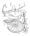
FIG. 1 is an isometric view of a bicycle attached to the device;
FIG. 2 is an exploded isometric view of the device;
FIG. 3 is an isometric view of the resistance device;
FIG. 4 is a cross section of the device showing the magnet position vs cylinder speed;
FIG. 5 is a cross section of the device showing the mechanical stop;
FIG. 6 is a cross section of the device showing the return spring;
FIG. 7 is a graph showing resistance vs speed;
FIG. 8 is a side view of the device in the folded position;
FIG. 9 is a side view of the device in the first step of unfolding;
FIG. 10 is a side view of the device in the second step of unfolding;
FIG. 11 is a side view of the device in the third step of unfolding;
FIG. 12 is a side view of the device in the unfolded position;
FIG. 13 is a top view of the device;
FIG. 14 is a side view of the device;
FIG. 15 is a bottom view of the device; and
FIG. 16 is a partial section view of a support as stored in the front frame.
FIG. 17 is an assembled view of the device as shown in FIG. 2.
DESCRIPTION OF THE PREFERRED EMBODIMENT
This disclosure describes an improved portable progressive resistance device 10 suitable for integration with a bicycle roller training device 12. The resistance device is shown with a driving mechanism, such as a bicycle 9 in FIG. 1 and the device as mounted on a training device 12 is shown in FIGS. 1 and 2. The progressive resistance device 10 is a conductive inner cylinder 14 (FIG. 3), having an inner surface 15 defining an internal chamber 16. The inner cylinder 14 also has an outer wall 18 with an external surface 19 that circumscribes the first, defining an annular area 20 between the two. One or more magnets 22 is carried on a pivotal magnet carrier 24 in proximity to inner surface 15 and housed within the internal chamber 16. Eddy currents produced in the inner cylinder 14 create a non-contacting frictional drag as the inner cylinder 14 spins relative to the magnet(s) 22. This drag causes a force that attempts to pull the magnet 22 from a resting position A (as shown in FIGS. 4-6) along with the rotation of the inner cylinder 14. The magnet 22 is mounted on a magnet carrier 24 that pivots on an axis 26 (FIG. 6) that is eccentrically offset from the rotational axis 28 of the cylinder. This rotation alters the magnet's proximity to the inner surface 15 by pulling the magnet carrier 24 to move in an eccentric orientation as relates to the rotational axis 28 of the cylinder. A torsional spring 35 (FIG. 4) opposes the force created by the eddy current and causes the system to achieve a state of equilibrium force balance. The pivotal position of the magnet carrier 24 to the inner cylinder 14 is closer as shown in position B and closer yet as shown in position C (FIG. 5) as cylinder 14 speed increases.
With the cylinder oriented such that rotation allows the magnet carrier to move against the torsional spring 35 (FIG. 4), the result is a non-linear progressive relationship between speed and resistance 50 as is shown in FIG. 7.
Another benefit of the progressive resistance device described herein is that when a linear relationship between speed and resistance is desired, a rotational stop may be implemented on the pivotal magnet carrier so that pivotal angle is limited, preventing the magnet(s) 22 from getting closer to the inner cylinder 14 when the rotational direction of the cylinder is reversed. The inner cylinder 14 can rotate in an opposite direction described above—allowing the same progressive resistance device 10 to provide either linear or proportional training depending on the direction of rotation of the inner cylinder 14. With the progressive resistance device reversed, the result will be a linear relationship of speed and resistance. Therefore, the progressive resistance device 10 described herein is unique in that it allows the user to select progressive resistance or linear resistance, as desired. The ability to make this selection is important because users training on rollers on any given day may prefer progressive resistance in one session and linear resistance in another session. In practice, the progressive resistance device is removable from the roller frame 61 (FIG. 1) and is reversible, to allow the user to select linear or progressive resistance.
For most bicycle riders, the use of a trainer having a single progressive resistance device described herein may be adequate. However, because a bicycle roller can comprise more than one device 10, the use of one or two progressive resistance devices described herein may be used in the place of the roller's cylinders to achieve differing levels of resistance. In other applications, a second roller is simply an idler and provides little to no rolling resistance.
By adjusting the spring rate, spring preload, number of magnets 22, and other variables it is possible to adjust the progressive relationship between resistance and speed 50 to suit the needs of the designer or the user.
Because of the heat generated by the eddy currents in the inner cylinder 14 during use, the second wall 18 and annular space 20 (FIG. 3) between the two cylinders may be necessary to prevent excessive heat from reaching the surface where the external surface 19 meets the tire 8. The annular space 20 between the cylinders 14, 18 can provide a thermal barrier between the cylinders and allow a cooling medium (typically air) through which it can pass to expel excessive heat. The inner 14 and outer 18 cylinders are mechanically connected, either by support structure 34 (FIG. 3) between the two or through the mounting of the cylinder to the axle through a bearing support 36, 38 (FIG. 3). Improved heat dissipation can be achieved through the implementation of cooling fins 40 on the bearing supports 36, 38 that mount the cylinders to the axle 30. The cooling fins 40 can be arranged on the bearing supports 36, 38 in such a manner to direct the flow of the cooling medium from one end of the cylinder to the other, thereby pulling heat from the assembly as the rider uses the device. One embodiment of the forced air cooling involves cooling fins 40 on the outer diameter of the bearing supports 36, 38 that pull air in on one side and force it out on the other side. Since the cylinder only produces heat while it is in motion, any features that move air during rotation are effective without requiring additional complexity or parts. It is also possible to incorporate features in the support structure 34 between the first and second cylinders 14, 18 such that the same cooling is accomplished as the cylinders 14, 18 are rotated relative to the axle 30. This could be from fan shaped assemblies integrated in bearing supports 36, 38 that are installed on at least one end of the cylinders 14, 18. Blades 40 integrated into the bearing supports pull cooler air in from one end of the cylinder and expel it through the opposite end. Cooling requirements may only dictate that one end of the cylinder incorporates fan shaped features to generate airflow.
An additional embodiment of this technology, to achieve a higher level of resistance on a single cylinder, is to include stationary magnets on the outer side of the progressive resistance device placed and oriented when the progressive resistance device is at rest. The poles of the moveable magnets inside the cylinder will oppose the stationary magnets outside the cylinder, thereby reducing the magnetic flux on the conductive cylinder wall and, when the progressive resistance device rotates during its normal operation, the moveable magnets inside the cylinder approach stationary magnets on the outside of the cylinder in such a way that the magnets are attracted by appropriate pole alignment; thereby increasing the magnetic flux on the conductive cylinder wall.
Applications of this technology are not limited to bicycle rollers and bicycle trainers, but are suitable in any application where a resistance mechanism is employed and it is desired that the resistance mechanism have a non-linear relationship to speed, such as a stationary bicycle, hand cycle ergometers, or any similar device. Because the progressive resistance device described herein is contained within a cylindrical drum and requires only that the cylinder be rotated relative to the axle, it can be driven by direct contact with a bicycle tire, or it can employ a chain and sprocket, a drive belt, or can be driven directly by any means to cause rotation of a cylinder on an axle.
A portable roller-type stationary bicycle trainer 12 includes a cycle attachment 139 shown in FIG. 1 using a quick release bolt 140 for one axle of the bicycle or attachment portion, shown as a front fork 141 with supports 120 that extend outward to stabilize the rider and a narrow roller that is driven by the driving tire of the bicycle (FIG. 1). Configurations of attaching cylindrical rollers with a roller frame 61 intended to appropriately space the rollers and allow for adjustment of the cylinders for use with various bicycles may be employed.
A roller frame 61 includes oppositely located sides 60 that support the axles 30 of the cylinders. The sides 60 have an upstanding portion 46 and a support portion 48 (FIG. 1). The upstanding portion 46 receives the progressive resistance devices 10 and affixes them using the axle 30. The opposing support portions 48 create a channel 33 as shown in FIG. 1. The roller frame 61 further includes a bolt 62 (FIG. 2) that extends between sides of the frame to pivotally hold an arm 64 at an arm attaching point 63. The arm has a first portion 66 and a second portion 68 (FIG. 12) that telescopingly slides over the first portion of the arm. The arm 64 has an upper surface 32 and a lower surface 31 and includes pivot points 52, 54 at each terminal end (FIG. 11). The pivot point 52 receives bolt 62 where it attaches to the roller frame 61, specifically sides 60. Pivot point 52 is offset from the main axis of the arm. The pivot point 54 is located oppositely and receives a bolt 94 (FIG. 2). The first portion 66 of the arm includes a bolt 70 (FIGS. 1 and 2) that is fixed within the first portion. The second portion 68 of the arm 64 includes a slot 74 that the bolt 70 slides within to allow telescoping. The portions 66, 68 of the arm 64 maybe slidingly adjusted and the nut 72 rotated to clamp them to a fixed and desired length. The arm 66 is pivotally connected to a front frame member 76. The front frame member 76 is an extrusion having a constant cross section for most of its length. The front frame member 76 includes two elongate tubes 80 that extend the length of the front frame member 76. Each tube 80 has a wall 82 with an inner surface 84. The tubes 80 are joined by a web 88 spanning between them on one side to form a flat side 90 (FIG. 1). Opposite the flat side 90 of the front frame member 76 is a groove 78 defined by the tubes 80 and the web 88. The web extends most of the length of the frame member 76 but is shortly less than the length of the tubes 80 and forms a notch 92 (FIG. 16) that extends between the tubes 80.
The arm 64 is pivotally connected to the front frame member 76 with a bolt 94 that extends through the tubes 80 that straddle the notch 92. The ends of the tubes 80 adjacent to the notch 92 receive plugs 124. The opposite ends of the tubes 80 are open. Intermediate to the ends of the tubes 80 are a pair of transverse holes 102. The transverse holes 102 have a first aperture 104 that is formed through wall 82 of the tube diagonally opposite where the web 88 joins each tube 80. The transverse hole has a perimeter that is circular in cross section. Each transverse hole 102 continues into its corresponding tube 80 to the inner surface 84 opposite the first aperture 104 to form a bottom portion of the transverse hole 102. The bottom portion of the hole 102 extends beyond the inner surface 84 but not through to the flat side 90 of the front frame. Where the web 88 joins each tube 80, there is optionally a gusset that is integral to the web 88 and corresponding tube 80. The gusset adds thickness where the web 88 joins each tube 80. The gusset is useful to provide additional material near the bottom portion of each transverse hole 102. The bottom portion is a cylindrical depression within the wall 82 having a flat circular bottom and a cylindrical perimeter. Within the flat circular bottom is a centrally located tapped hole 134. All shown in best detail on exploded FIG. 2.
Legs 120 are made from round tubular aluminum but can be made from other structural materials. One end of the leg 120 receives a plug 122 that provides a non-slip, non-marring end to the legs 120 that will rest on a floor. The plug 122 is shown as a rounded end rubber plug. The opposite end of the legs 120 are cut squarely to from a second end. From the center, near the second end of each leg 120 is an attaching end, shown as a threaded stud 128 extending therefrom. The threaded stud 128 is designed to be screwed into a threaded hole 134. When this is done, the transverse hole 102 sets an oblique angle between the legs 120 and the tubes 80 to which the legs 120 extend from. The second end fits within the bottom portion of its corresponding transverse hole 102 and is supported laterally by the perimeter in the inner surface near the bottom portion. The transverse hole 102 supports the leg 120 at a distance spaced from the bottom portion to provide a rigidly supported connection between the leg 120 and the front frame member 76.
When the legs 120 are not in the transverse holes 102, they are stored in the tubes 80. The inner surface 84 forms a cavity slightly larger than the outer diameter of the leg 120. The leg 120 is inserted into the tube 80. Each tube 80 includes a threaded hole 117 also referred to as a receiver that receives the stud 128 so that the leg 120 may securely held within a tube 80 when threaded stud 128 is screwed into a corresponding threaded hole 117.
The groove 78 is capable of receiving the arm 64 within it when the arm 64 is folded onto the front frame member 76. When the arm 64 is folded into the groove 78, it rests within the groove 78 and in between the two tubes 80. The arm 64 may be adjusted so that the length of the arm 64 locates the open ends of the tubes 80 adjacent to the pivot where the arm 64 is joined to the roller frame 61. From this position, the front frame member 76 may be folded to the sides of the roller frame 61 opposite where the cylinders are mounted. Because the cylinders have their outermost surface spaced from the bottom of the roller frame, the flat portion of the front frame member 76 may rest substantially aligned with the bottom of the roller frame when the front frame member 76 is folded in this position with respect to the roller frame 61. A quick release bolt 140 (FIG. 2) is located near the open ends of the tubes 80 on the front frame member 76. The quick release is received into notches 142 (FIG. 2) that are located between the pivot where the arm 64 is attached to the roller frame 61 and the cylinders. Once the quick release bolt 140 is located in the notches 142, it may be tightened to secure the entire resistance training device into a small portable package. This small folded resistance training device can fit easily into the overhead compartment of a plane for easy travel.
When the progressive resistance device is used, the driven wheel of a bicycle is placed on the two rear cylinders and the front wheel of a bicycle may be removed and the front axle or fork is mounted using the bolt 140 to the front frame 76 that supports the front and stabilizes the bicycle frame. In this application, not requiring the skill of the user to balance, the driven wheel of a bicycle is placed between the two roller cylinders and aligned in such a way that the tire of the bicycle, tricycle, or handcycle remains in contact with the roller cylinders during use. In a manner as is known, the user pedals the bicycle, tricycle or handcycle so as to rotate the driven wheel which in turn rotates the cylinder or cylinders supporting the driven wheel.
As is depicted in FIGS. 8-12, the device 12 can be converted between a stored configuration and a use configuration. The stored configuration is shown in FIGS. 13-15. The first step to convert the device 12 to the use configuration consists of freeing the legs 120. This consists of unthreading the stud 128 from the threaded hole 117 and sliding the leg 120 from the tube 80 as shown in FIG. 8. Next, the bolt 140 is loosened, freeing it from the notches 142, the release of bolt 140 and pivoting of the arm 64 and front frame 76 are shown in FIG. 9. The next step involves pivoting the front frame 76 from the arm 64. This is shown in FIG. 10. The next step is to secure the supports 120 in the transverse holes 102. This is shown in FIG. 11. The next step is to affix a bicycle or similar device to the bolt 140 and lock it down to secure it. In FIG. 1, the front fork of a bicycle is attached. Lastly, the arm 64 is adjusted by sliding the first portion 66 relative to second portion 68 in order to properly position the driving wheel of the bicycle or other device on the progressive resistance device 10 and the bolt 70 and nut 72 are used to fix the length of the arm 64. Proper positioning is shown in FIGS. 1 and 12. In use, the training device 12 contacts the floor on plugs 122 and 124 and support portion 48 of the roller frame 61.
In order to make the folded position of the training device 12 as compact as possible, the front frame 76 partially fits inside the channel that is created between the support portions 48 of the roller frame 61. The training device 12 can be fixed in the folded position by locking the bolt 140 in the notches 142. As shown in the folded and stored position in FIG. 13, the front frame is visible, specifically flat side 90. It is possible for the flat side 90 to directly contact the external surface 19 (FIG. 3) of the progressive resistance device 10.
It is understood that while certain aspects of the disclosed subject matter have been shown and described, the disclosed subject matter is not limited thereto and encompasses various other embodiments and aspects. No specific limitation with respect to the specific embodiments disclosed herein is intended or should be inferred. Modifications may be made to the disclosed subject matter as set forth in the following claims.

Claims (13)

What is claimed is:
1. A portable training device adapted to be used with a driving mechanism having a driving wheel and a mounting portion, said training device having:
a roller frame having an upstanding portion and a support portion, said support portion having a channel, said roller frame having an arm attaching point and a notch adapted to receive a portion of a front frame;
a resistance device rotatably affixed to said roller frame on an axle, said resistance device rotatable about a central axis and adapted to resist rotation with respect to said central axis;
a telescoping arm being an elongate member telescopingly fixable between a collapsed position and an extended position, said telescoping arm having an upper surface and a lower surface to define a thickness, said telescoping arm pivotably affixed at a first pivot point located at a first terminal end to said arm attaching point, said telescoping arm pivotably affixed at a second terminal end to a first distal end of said front frame, said first pivot point biased toward said lower surface;
said front frame being an elongate member having a second distal end located opposite said first distal end, said second distal end having a cycle attachment adapted to affix said mounting portion of said driving mechanism to said training device, said front frame including an aperture located between said first and second distal end, said aperture adapted to receive a support and obliquely angled with respect to said front frame, said front frame having a groove adapted to receive said telescoping arm;
said support being an elongate member having an attaching end adapted to be received by said aperture and affixed to said front frame;
said telescoping arm pivotable between a first position outwardly extending from said roller frame and a second position inverted with respect to said first position and overlaying said channel, said front frame is pivotable between a first position where said second distal end is located at a relatively far position from said roller frame, and a second position where said cycle attachment is located in said notch.
2. The portable training device of claim 1, a portion of said front frame is located in said channel when said front frame is in said second position.
3. The portable training device of claim 2, a portion of said telescoping arm is located in said groove when said front frame is in said second position.
4. The portable training device of claim 3, said groove in said front frame having a depth greater than said thickness of said telescoping arm.
5. The portable training device of claim 1, said resistance device having an inner cylinder having a wall defining a first inner chamber and said central axis, said resistance device having an outer cylinder having a wall, said outer cylinder being affixed to said inner cylinder and being rotatable about said central axis, said outer cylinder circumscribing said inner cylinder to define an annular space between said wall of said inner cylinder and said wall of said outer cylinder, said inner and outer cylinders being concentric, said axle extending through said central axis of said inner cylinder about which said inner and outer cylinders are rotatable, a pivotal magnet carrier pivotally mounted to said axle within said inner cylinder, a magnet affixed to said pivotal magnet carrier and spaced adjacent to said wall of said inner cylinder, within said inner cylinder sufficiently near to said inner cylinder to generate eddy currents when said inner cylinder is rotated with respect to said magnet, a spring, providing torsional resistive force to pivoting of said pivotal magnet carrier from eddy currents when said inner cylinder is rotated with respect to said axle.
6. The portable training device of claim 5, said pivotal magnet carrier has a first position wherein said magnet is spaced inwardly within said inner cylinder a distance relatively farthest from said inner cylinder and pivotable to a second position, locating said magnet relatively nearer to said inner cylinder than in said first position.
7. A portable training device having:
a roller frame having an upstanding portion, a support portion, and a channel, said roller frame having an arm attaching point and a notch;
a resistance device rotatably affixed to said upstanding portion on an axle, said resistance device rotatable about a central axis and adapted to resist rotation with respect to said axle;
an arm being an elongate member having an upper surface and a lower surface to define a thickness, said arm pivotably affixed at a first pivot point located at a first terminal end to said arm attaching point, said arm pivotably affixed at a second terminal end to a first distal end of a front frame;
said front frame being an elongate member having a second distal end located opposite said first distal end, said second distal end having a cycle attachment adapted to affix a portion of a cycle to said training device;
said arm moveable between a first position outwardly extending from said roller frame and a second position inverted with respect to said first position and partially located in said channel, said front frame is moveable between a first position where said second distal end is located at a relatively far position from said roller frame, and a second position where said second distal end is adjacent to said roller frame; and
a portion of said front frame is located in said channel when said front frame is in said second position, said front frame having a groove spanning said first and second distal ends, a portion of said arm is located in said groove when said front frame is in said second position.
8. The portable training device of claim 7, said resistance device having a first cylinder having a wall defining a first inner chamber and said central axis, said resistance device having a second cylinder, affixed to said first cylinder, having a wall and rotatable about said central axis, said second cylinder circumscribing said first cylinder to define an annular space between said wall of said first cylinder and said wall of said second cylinder, said first and second cylinders being concentric, said axle extending through said central axis of said first cylinder about which said first and second cylinders are rotatable, a pivotal magnet carrier pivotally mounted to said axle within said first cylinder, a magnet affixed to said pivotal magnet carrier and spaced adjacent to said wall of said first cylinder, within said first cylinder sufficiently near to said first cylinder to generate eddy currents when said first cylinder is rotated with respect to said magnet, a spring, providing torsional resistive force to pivoting of said pivotal magnet carrier from eddy currents when said first cylinder is rotated with respect to said axle.
9. The portable training device of claim 8, said arm being telescopically slidable between an expanded and a compressed position, said arm fixable at a position between said expanded and compressed positions.
10. The portable training device of claim 9, said first pivot point offset from a central axis of said arm.
11. The portable training device of claim 10, said front frame having an aperture adapted to receive a support, said support being an elongate member and supporting a portion of said front frame when said support is received in said aperture.
12. The portable training device of claim 11, said support obliquely angled with respect to said front frame when said support is received in said aperture.
13. The portable training device of claim 7, said front frame member having a tube with an opening at said second distal end, said tube adapted to receive a support, said tube having a receiver adapted to affix said support at an attaching end when said support is located in said tube.
US14/612,686 2014-02-04 2015-02-03 Portable progressive resistance exercise device Active US9381396B2 (en)

Priority Applications (1)

Application Number Priority Date Filing Date Title
US14/612,686 US9381396B2 (en) 2014-02-04 2015-02-03 Portable progressive resistance exercise device

Applications Claiming Priority (2)

Application Number Priority Date Filing Date Title
US201461935583P 2014-02-04 2014-02-04
US14/612,686 US9381396B2 (en) 2014-02-04 2015-02-03 Portable progressive resistance exercise device

Publications (2)

Publication Number Publication Date
US20150217158A1 US20150217158A1 (en) 2015-08-06
US9381396B2 true US9381396B2 (en) 2016-07-05

Family

ID=53753992

Family Applications (1)

Application Number Title Priority Date Filing Date
US14/612,686 Active US9381396B2 (en) 2014-02-04 2015-02-03 Portable progressive resistance exercise device

Country Status (1)

Country Link
US (1) US9381396B2 (en)

Cited By (7)

* Cited by examiner, † Cited by third party
Publication number Priority date Publication date Assignee Title
US20170216698A1 (en) * 2016-01-28 2017-08-03 Tacx Roerend En Onroerend Goed B.V. Bicycle trainer
US9814931B1 (en) * 2013-07-29 2017-11-14 Kurt Manufacturing Company, Inc. Bicycle trainer with roller speed sensor
US20180036619A1 (en) * 2015-02-27 2018-02-08 Keun Woo Kim Bicycle exercise apparatus
US11299235B2 (en) 2019-12-30 2022-04-12 Imran Durrani Foot and hand pedaled bicycle assembly
US11351434B2 (en) 2018-05-08 2022-06-07 Tacx B.V. Power measurement device
US11400340B2 (en) * 2019-06-26 2022-08-02 Mathias Seidler Device for a person to sit on for training purposes for executing a leg rotation movement similar to riding a bicycle
US11566608B2 (en) * 2019-09-04 2023-01-31 Planet Water, LLC Aquacycle pump and method of use

Families Citing this family (14)

* Cited by examiner, † Cited by third party
Publication number Priority date Publication date Assignee Title
CN105749527A (en) * 2016-04-29 2016-07-13 徐峰 Hobbing type bicycle riding balance simulator suitable for children
CN105944358A (en) * 2016-04-29 2016-09-21 徐峰 Elastic cable type bicycle riding intelligent simulation system applicable to children
CN105771214A (en) * 2016-04-29 2016-07-20 徐峰 Rotary bicycling balance simulator suitable for children
CN105771213A (en) * 2016-04-29 2016-07-20 徐峰 Elastic pull cord type bicycling balance simulator suitable for children
CN105797343A (en) * 2016-04-29 2016-07-27 徐峰 Self-fixing rotary type bicycle riding balance simulator applicable to children
CN105727540A (en) * 2016-04-29 2016-07-06 徐峰 Inhaul cable type cycling intelligent simulation system applicable to children
CN105944357A (en) * 2016-04-29 2016-09-21 徐峰 Push-pull rod type bicycle riding intelligent simulation system applicable to children
CN105879311A (en) * 2016-04-29 2016-08-24 徐峰 Oscillating bar type bicycle riding intelligent simulation system suitable for children
CN105727541A (en) * 2016-04-29 2016-07-06 徐峰 Cable type bicycle riding balance simulator suitable for children
CN105749526A (en) * 2016-04-29 2016-07-13 徐峰 Push-pull rod type bicycle riding balance simulator suitable for children
US11260280B2 (en) 2016-08-05 2022-03-01 Larry C. Papadopoulos Bicycle trainer permitting steering and tilting motion
WO2018027216A1 (en) * 2016-08-05 2018-02-08 Papadopoulos Larry C Bicycle trainer permitting steering and tilting motion
US10493320B2 (en) * 2017-07-19 2019-12-03 Anant Porwal Exercise assembly
US10384111B2 (en) * 2017-11-08 2019-08-20 Shu-Chiung Liao Lai Bicycle trainer

Citations (22)

* Cited by examiner, † Cited by third party
Publication number Priority date Publication date Assignee Title
FR2315962A1 (en) * 1975-07-02 1977-01-28 Manufrance Flexible support for cycle while training - has adjustable frame with rollers to support back wheel and telescopic arms with collar gripping head tube
US4026546A (en) * 1976-02-09 1977-05-31 Kabushiki Kaisha Kawamura Saikuru Bicycle pedaling stand
US4595194A (en) * 1983-09-14 1986-06-17 Giovanni Previtali Bag portable bicycle training apparatus
US4976424A (en) * 1987-08-25 1990-12-11 Schwinn Bicycle Company Load control for exercise device
EP0621058A1 (en) 1993-04-21 1994-10-26 Life Fitness Step exercise apparatus
US6042517A (en) 1998-09-10 2000-03-28 Bell Sports, Inc. Bicycle trainer magnetic resistance device
US20020137601A1 (en) * 2001-03-23 2002-09-26 Tobias Andrew J. Exercise device
US6712737B1 (en) * 1999-10-06 2004-03-30 Neil Nusbaum Exercise apparatus with video effects synchronized to exercise parameters
US6857992B1 (en) 2002-05-13 2005-02-22 Saris Cysling Group, Inc. Magnetic resistance system for a roller-type bicycle trainer
US20050064999A1 (en) 2003-09-22 2005-03-24 Rui-Zung Qiu Damping device for exercising cycle
US6945917B1 (en) * 2000-11-21 2005-09-20 Racer-Mate, Inc. Resistance exercise apparatus and trainer
US20050209064A1 (en) * 2004-03-15 2005-09-22 Peterson Lewis D Bicycle trainer
US6964633B2 (en) 2003-02-20 2005-11-15 Saris Cycling Group, Inc. Exercise device with an adjustable magnetic resistance arrangement
US7011607B2 (en) 2002-01-23 2006-03-14 Saris Cycling Group, Inc. Variable magnetic resistance unit for an exercise device
EP1683550A1 (en) 2005-01-24 2006-07-26 Bernhard Lang Simulator with variable adaptation to real conditions
US20060217237A1 (en) * 2004-12-30 2006-09-28 Rhodes Jeffrey F Exercise apparatus
US7585258B2 (en) 2005-03-23 2009-09-08 Saris Cycling Group, Inc. Power sensing eddy current resistance unit for an exercise device
US20090283648A1 (en) * 2008-05-15 2009-11-19 Cycling & Health Tech Industry Research & Development Center Front-wheel steering gear having function of outputting directional signals
WO2010104405A2 (en) 2009-03-10 2010-09-16 Holmes Solutions Limited Improvements in and relating to braking mechanisms
US8430797B2 (en) * 2010-05-24 2013-04-30 Kuo Hui Wan Support for supporting a bicycle used as an exerciser
US20140296038A1 (en) * 2012-09-24 2014-10-02 SportCrafters, Inc. Progressive Resistance System for an Exercise Device
US20150133272A1 (en) * 2013-11-14 2015-05-14 Larry C. Papadopolous Light Weight Portable Bicycle Rollers

Patent Citations (22)

* Cited by examiner, † Cited by third party
Publication number Priority date Publication date Assignee Title
FR2315962A1 (en) * 1975-07-02 1977-01-28 Manufrance Flexible support for cycle while training - has adjustable frame with rollers to support back wheel and telescopic arms with collar gripping head tube
US4026546A (en) * 1976-02-09 1977-05-31 Kabushiki Kaisha Kawamura Saikuru Bicycle pedaling stand
US4595194A (en) * 1983-09-14 1986-06-17 Giovanni Previtali Bag portable bicycle training apparatus
US4976424A (en) * 1987-08-25 1990-12-11 Schwinn Bicycle Company Load control for exercise device
EP0621058A1 (en) 1993-04-21 1994-10-26 Life Fitness Step exercise apparatus
US6042517A (en) 1998-09-10 2000-03-28 Bell Sports, Inc. Bicycle trainer magnetic resistance device
US6712737B1 (en) * 1999-10-06 2004-03-30 Neil Nusbaum Exercise apparatus with video effects synchronized to exercise parameters
US6945917B1 (en) * 2000-11-21 2005-09-20 Racer-Mate, Inc. Resistance exercise apparatus and trainer
US20020137601A1 (en) * 2001-03-23 2002-09-26 Tobias Andrew J. Exercise device
US7011607B2 (en) 2002-01-23 2006-03-14 Saris Cycling Group, Inc. Variable magnetic resistance unit for an exercise device
US6857992B1 (en) 2002-05-13 2005-02-22 Saris Cysling Group, Inc. Magnetic resistance system for a roller-type bicycle trainer
US6964633B2 (en) 2003-02-20 2005-11-15 Saris Cycling Group, Inc. Exercise device with an adjustable magnetic resistance arrangement
US20050064999A1 (en) 2003-09-22 2005-03-24 Rui-Zung Qiu Damping device for exercising cycle
US20050209064A1 (en) * 2004-03-15 2005-09-22 Peterson Lewis D Bicycle trainer
US20060217237A1 (en) * 2004-12-30 2006-09-28 Rhodes Jeffrey F Exercise apparatus
EP1683550A1 (en) 2005-01-24 2006-07-26 Bernhard Lang Simulator with variable adaptation to real conditions
US7585258B2 (en) 2005-03-23 2009-09-08 Saris Cycling Group, Inc. Power sensing eddy current resistance unit for an exercise device
US20090283648A1 (en) * 2008-05-15 2009-11-19 Cycling & Health Tech Industry Research & Development Center Front-wheel steering gear having function of outputting directional signals
WO2010104405A2 (en) 2009-03-10 2010-09-16 Holmes Solutions Limited Improvements in and relating to braking mechanisms
US8430797B2 (en) * 2010-05-24 2013-04-30 Kuo Hui Wan Support for supporting a bicycle used as an exerciser
US20140296038A1 (en) * 2012-09-24 2014-10-02 SportCrafters, Inc. Progressive Resistance System for an Exercise Device
US20150133272A1 (en) * 2013-11-14 2015-05-14 Larry C. Papadopolous Light Weight Portable Bicycle Rollers

Cited By (8)

* Cited by examiner, † Cited by third party
Publication number Priority date Publication date Assignee Title
US9814931B1 (en) * 2013-07-29 2017-11-14 Kurt Manufacturing Company, Inc. Bicycle trainer with roller speed sensor
US20180036619A1 (en) * 2015-02-27 2018-02-08 Keun Woo Kim Bicycle exercise apparatus
US20170216698A1 (en) * 2016-01-28 2017-08-03 Tacx Roerend En Onroerend Goed B.V. Bicycle trainer
US10112098B2 (en) * 2016-01-28 2018-10-30 Tacx Roerend En Onroerend Goed B.V. Bicycle trainer
US11351434B2 (en) 2018-05-08 2022-06-07 Tacx B.V. Power measurement device
US11400340B2 (en) * 2019-06-26 2022-08-02 Mathias Seidler Device for a person to sit on for training purposes for executing a leg rotation movement similar to riding a bicycle
US11566608B2 (en) * 2019-09-04 2023-01-31 Planet Water, LLC Aquacycle pump and method of use
US11299235B2 (en) 2019-12-30 2022-04-12 Imran Durrani Foot and hand pedaled bicycle assembly

Also Published As

Publication number Publication date
US20150217158A1 (en) 2015-08-06

Similar Documents

Publication Publication Date Title
US9381396B2 (en) Portable progressive resistance exercise device
US9044635B2 (en) Exercise bicycle with magnetic flywheel brake
US7470220B2 (en) Bicycle mounted exercise and training device
US20040053751A1 (en) Bicycle trainer allowing laterial rocking motion
US9944338B2 (en) Device and method for a collapsible electric scooter
US9855480B2 (en) Bicycle trainer
US9393475B2 (en) Progressive resistance system for an exercise device
US9517376B2 (en) Portable and attachable bicycle trainer
US8267846B2 (en) Exercise wheel
US6736761B2 (en) Stationary bicycle resistance generator
US5026047A (en) Quick release mechanism for bicycle trainer
US8403342B1 (en) Bicycle ski attachment assembly
US4768782A (en) Bicycle exercising apparatus
ES2706006T3 (en) Cycling accessory and method of use
JP2002011115A (en) Resistance unit for exercising apparatus and bicycle training apparatus
US20010041648A1 (en) Bicycle trainer with movable resistance Device
US20150057129A1 (en) Elliptical Trainer
US20180036574A1 (en) Stationary Wind Trainer
US20180264305A1 (en) Eddy current cycling resistance apparatus
US9993684B2 (en) Exercise apparatus with travel path constraining unit
US20190002055A1 (en) All Limb Powered And Steered Front Wheel Drive Land Vehicle
US6780143B2 (en) Eccentric cycling trainer
US11266873B1 (en) Bicycle-type exercise apparatus
US7163225B2 (en) Foot peg
US20120065028A1 (en) Exercise bicycle

Legal Events

Date Code Title Description
AS Assignment

Owner name: SPORTCRAFTERS, INC., INDIANA

Free format text: ASSIGNMENT OF ASSIGNORS INTEREST;ASSIGNORS:COLAN, PETER V;KULWICKI, PATRICK T;SIGNING DATES FROM 20150128 TO 20150129;REEL/FRAME:034876/0430

STCF Information on status: patent grant

Free format text: PATENTED CASE

MAFP Maintenance fee payment

Free format text: PAYMENT OF MAINTENANCE FEE, 4TH YR, SMALL ENTITY (ORIGINAL EVENT CODE: M2551); ENTITY STATUS OF PATENT OWNER: SMALL ENTITY

Year of fee payment: 4

AS Assignment

Owner name: FEEDBACK SPORTS LLC, COLORADO

Free format text: ASSIGNMENT OF ASSIGNORS INTEREST;ASSIGNOR:SPORTCRAFTERS, INC.;REEL/FRAME:064873/0471

Effective date: 20230912

MAFP Maintenance fee payment

Free format text: PAYMENT OF MAINTENANCE FEE, 8TH YR, SMALL ENTITY (ORIGINAL EVENT CODE: M2552); ENTITY STATUS OF PATENT OWNER: SMALL ENTITY

Year of fee payment: 8